WO2017155014A1 - 電解水生成装置 - Google Patents
電解水生成装置 Download PDFInfo
- Publication number
- WO2017155014A1 WO2017155014A1 PCT/JP2017/009372 JP2017009372W WO2017155014A1 WO 2017155014 A1 WO2017155014 A1 WO 2017155014A1 JP 2017009372 W JP2017009372 W JP 2017009372W WO 2017155014 A1 WO2017155014 A1 WO 2017155014A1
- Authority
- WO
- WIPO (PCT)
- Prior art keywords
- water
- acidic
- electrolyzed
- channel
- generating apparatus
- Prior art date
- Legal status (The legal status is an assumption and is not a legal conclusion. Google has not performed a legal analysis and makes no representation as to the accuracy of the status listed.)
- Ceased
Links
Images




Classifications
-
- B—PERFORMING OPERATIONS; TRANSPORTING
- B01—PHYSICAL OR CHEMICAL PROCESSES OR APPARATUS IN GENERAL
- B01F—MIXING, e.g. DISSOLVING, EMULSIFYING OR DISPERSING
- B01F23/00—Mixing according to the phases to be mixed, e.g. dispersing or emulsifying
- B01F23/20—Mixing gases with liquids
-
- C—CHEMISTRY; METALLURGY
- C02—TREATMENT OF WATER, WASTE WATER, SEWAGE, OR SLUDGE
- C02F—TREATMENT OF WATER, WASTE WATER, SEWAGE, OR SLUDGE
- C02F1/00—Treatment of water, waste water, or sewage
- C02F1/46—Treatment of water, waste water, or sewage by electrochemical methods
Definitions
- the present invention relates to an electrolyzed water generating apparatus.
- an electrolyzed water generating apparatus including an electrolyzer that can continuously take electrolyzed water.
- the electrolytic cell is partitioned and formed through a diaphragm into an anode chamber in which a positive electrode is provided to generate acidic water and a cathode chamber in which a negative electrode is provided to generate alkaline water.
- An electrolyzed water generating apparatus includes an anode chamber having an anode and a cathode chamber having a cathode, and electrolyzing water supplied to the anode chamber and the cathode chamber to dissolve oxygen dissolved therein. Is generated in the anode chamber, and at least one of alkaline water and acidic water generated in the electrolysis portion, and an electrolysis portion that generates alkaline water in which the hydrogen is dissolved in the cathode chamber, A water intake passage, a reflux bypass passage for joining a part of the acidic water discharged from the anode chamber to the water supplied to the anode chamber, and a miniaturized portion provided in the water intake passage. .
- a reflux bypass flow path for joining a part of the acidic water discharged from the anode chamber to the water supplied to the anode chamber dissolution is performed while suppressing an increase in pH.
- Alkaline water with increased hydrogen concentration can be taken.
- the concentration of dissolved hydrogen in alkaline water can be further improved by making the bubbles of hydrogen not dissolved in alkaline water, for example, minute by the micronized portion.
- the miniaturization unit may miniaturize at least a part of hydrogen bubbles not dissolved in the alkaline water flowing in the intake channel to a size of less than 1 millimeter (second). Configuration).
- the dissolved hydrogen concentration in the alkaline water can be further improved.
- the 4th structure by providing a micronization part and making the pressure of the flowing water between an electrolysis part and a micronization part into 0.01MPa or more and 1MPa or less, hydrogen dissolved in the alkaline water to take in water Since it can be increased, the dissolved hydrogen concentration of alkaline water can be improved.
- the intake channel takes in alkaline water
- the electrolyzed water generating device further includes a drain channel for draining acidic water discharged from the anode chamber, and the reflux
- the bypass flow path is formed on the acidic water branch flow path for diverting part of the acidic water from the middle of the drainage path and the supply path for supplying water to the anode chamber, and the acidic water flowing through the acidic water branch flow path It is good also as a structure provided with the acidic water recirculation
- the acidic water can be recirculated to the anode chamber while reducing the amount of acidic water that becomes drainage.
- a limiting pressurization unit that is provided in the drainage channel or the acidic water branching channel and limits the flow rate of acidic water flowing through the drainage channel or the acidic water branching channel to pressurize the anode chamber It is good also as a structure further equipped with (6th structure).
- the cathode chamber is pressurized by pressurizing the anode chamber.
- the cathode chamber can be further increased in hydrogen dissolved in alkaline water by being pressurized from the anode chamber side in addition to the pressurization by the miniaturized portion provided in the intake channel.
- the neutralization reaction of hydrogen ions and hydroxide ions is promoted by pressurizing the anode chamber, an increase in pH of alkaline water can be suppressed.
- the said limitation pressurization part is good also as a structure which is provided in the said acidic water branch flow path, and contains the recirculation
- the pH of the generated alkaline water can be adjusted by adjusting the flow rate of the acidic water to be refluxed.
- the flow rate of the acidic water to be refluxed can be adjusted by adjusting the flow rate of the acidic water to be drained, the pH of the generated alkaline water can be adjusted.
- a reflux water amount adjustment unit that is provided in the acidic water branch flow channel and adjusts the flow rate of the acidic water flowing through the acidic water branch flow channel may be further provided (9th configuration).
- the pH of the generated alkaline water can be adjusted by adjusting the flow rate of the acidic water to be refluxed.
- the flow rate of the acidic water to be refluxed can be adjusted by adjusting the flow rate of the acidic water to be drained, the pH of the generated alkaline water can be adjusted.
- the miniaturized portion has at least a part of hydrogen bubbles not dissolved in the alkaline water having a size of 1 micrometer or more and less than 1 millimeter, and 1 nanometer. You may make it miniaturize to the magnitude
- At least part of the hydrogen bubbles not dissolved in the alkaline water is made into at least one of microbubbles and nanobubbles, so that the dissolved hydrogen concentration is improved so as to be easily dissolved in water. Can be made.
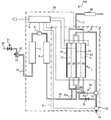
- FIG. 1 is a diagram illustrating a configuration of an electrolyzed water generating apparatus 100 according to an embodiment.
- the electrolyzed water generating apparatus 100 includes an electrolysis unit 2, a water purification unit 3, an addition unit 4, a control unit 5, and a micronization unit 80.
- the electrolysis unit 2, the water purification unit 3, the addition unit 4, and the control unit 5 are housed and disposed in a substantially box-shaped casing 20.
- the electrolysis unit 2 is composed of an electrolytic cell 1 and flow pipes disposed around the electrolytic cell 1.
- Raw water (tap water) is supplied to the electrolytic cell 1 from a water pipe 30 through a water tap 31.
- the raw water is neutral water having a pH of about 7.
- the raw water supplied to the electrolytic cell 1 is not limited to tap water as long as it is drinkable water having a pH of about 6 to 8 that is not subjected to extreme pH adjustment.
- a branch tap 32 is disposed in the water tap 31.
- the branch plug 32 is connected to one of the water supply hoses 33, and the other of the water supply hoses 33 is connected to the inlet of the water purification unit 3.
- the water purification unit 3 has a function of purifying raw water (tap water) supplied from the water pipe 30.
- the water purification unit 3 has a porous member such as activated carbon, thereby functioning as an adsorbing unit that adsorbs impurities contained in raw water (tap water) supplied from the water pipe 30.
- the water purifier 3 functions as a filtering means that includes a relatively coarse filter such as a metal mesh, cloth material, filter paper, and the like, and a hollow fiber membrane that can remove even germs.
- the outlet of the water purification unit 3 is connected to the inlet of the flow sensor 51.
- the flow sensor 51 is configured to be able to measure the amount of flowing water.
- the flow sensor 51 includes a propeller at the center thereof, and measures the amount of flowing water based on the number of rotations of the propeller.
- the outlet of the flow sensor 51 is connected to the inlet of the addition unit 4.
- the addition unit 4 contains a calcium agent for adding calcium to the purified water after purification by the water purification unit 3.
- the calcium agent contains calcium lactate, calcium glycerophosphate, etc., and makes the calcium agent elution easily by bringing purified water into contact with the calcium agent and eluting calcium.
- the outlet of the addition unit 4 is connected to the main raw water supply path 24.
- the main raw water supply path 24 branches into a secondary raw water supply path 24a and a secondary raw water supply path 24b in the middle.
- the secondary raw water supply path 24a is connected to the inlets of the first electrolysis chamber 25 and the fourth electrolysis chamber 28 of the electrolytic cell 1 described later, and the secondary raw water supply path 24b is the second electrolysis of the electrolytic cell 1 described later.
- the inlet of the chamber 26 and the third electrolysis chamber 27 is connected.
- the electrolytic cell 1 is provided with an anode and a cathode, and the raw water in the electrolytic cell 1 is electrolyzed by applying a voltage between the anode and the cathode.
- the raw water is electrolyzed, acidic water is generated from the anode side, oxygen is generated, alkaline water is generated from the cathode side, and hydrogen is generated.
- the electrolytic cell 1 includes a first electrode plate 21 located at the center, and a second electrode plate 22 and a third electrode plate 23 located so as to sandwich the first electrode plate 21.
- a first electrode plate 21 located at the center
- a second electrode plate 22 and a third electrode plate 23 located so as to sandwich the first electrode plate 21.
- platinum-coated titanium whose titanium surface is covered with platinum can be used.
- the diaphragm 12 is disposed between the first electrode plate 21 and the second electrode plate 22 and between the first electrode plate 21 and the third electrode plate 23, respectively.
- a first electrolysis chamber 25, a second electrolysis chamber 26, a third electrolysis chamber are provided in the electrolytic cell 1, the first electrode plate 21, the second electrode plate 22, the third electrode plate 23, and the diaphragm 12, a first electrolysis chamber 25, a second electrolysis chamber 26, a third electrolysis chamber are provided.
- a chamber 27 and a fourth electrolysis chamber 28 are defined.
- the second electrode plate 22 and the third electrode plate 23 are supplied with electric power from a power supply circuit (not shown) provided in the control unit 5 disposed in the casing 20 and have the same polarity of the cathode or the anode.
- the first electrode plate 21 is an electrode plate having a polarity opposite to that of the second electrode plate 22 and the third electrode plate 23.
- the second electrode plate 22 and the third electrode plate 23 are used as cathodes, and the first electrode plate 21 is used as an anode. Accordingly, the first electrolysis chamber 25 and the fourth electrolysis chamber 28 become cathode chambers to generate alkaline water (electrolytic hydrogen water), and the second electrolysis chamber 26 and the third electrolysis chamber 27 become anode chambers. Acid water is generated. That is, the first electrolysis chamber 25 and the fourth electrolysis chamber 28 are alkaline water generation chambers, and the second electrolysis chamber 26 and the third electrolysis chamber 27 are acid water generation chambers.
- Each of the electrolysis chambers 25, 26, 27, and 28 is provided with a water inlet and outlet.
- the flow paths communicating with the outlets of the first electrolysis chamber 25 and the fourth electrolysis chamber 28 merge with each other to form the intake channel 17. From the intake channel 17, alkaline water having a desired pH can be taken.
- the flow paths communicating with the outlets of the second electrolysis chamber 26 and the third electrolysis chamber 27 merge together to form the drainage channel 18. Acidic water flowing through the drainage channel 18 can be drained via the solenoid valve 50.
- the solenoid valve 50 is provided in the middle of the drainage channel 18 and on the downstream side of the connection part with the acidic water branching channel 70a described later, and functions as a drainage amount adjusting unit that adjusts the flow rate of the acidic water to be drained.
- the electromagnetic valve 50 is provided in the vicinity of the discharge port 52.
- the polarities of the first electrode plate 21, the second electrode plate 22, and the third electrode plate 23 can be reversed.
- the second electrode plate 22 and the third electrode plate 23 become the anode
- the first electrode plate 21 becomes the cathode
- the first electrolysis chamber 25 and the fourth electrolysis chamber 28 become the anode.
- the second electrolysis chamber 26 and the third electrolysis chamber 27 become the cathode chamber (alkaline water generation chamber). In this case, acidic water is taken from the intake channel 17, and alkaline water is drained from the drain channel 18.
- the above-described secondary raw water supply path 24 b is connected to the drainage path 18 via the check valve 72.
- the check valve 72 always has a role of stopping the flow of water from the drainage channel 18 toward the auxiliary raw water supply channel 24b.
- the check valve 72 also stops the flow of water from the secondary raw water supply path 24b toward the drainage channel 18, and when there is no water pressure at the time of water flow, each electrolysis chamber 25 , 26, 27, 28 and the water accumulated in each flow path is controlled to flow to the drainage channel 18.
- a reflux bypass flow path 70 is provided for causing a part of the acidic water discharged from the anode chamber to join the raw water supplied to the anode chamber.
- the reflux bypass flow path 70 includes an acidic water branch flow path 70a for diverting part of the acidic water from the middle of the drainage path 18 for discharging the acidic water discharged from the anode chamber, and a secondary raw water supply for supplying water to the anode chamber.
- An acidic water reflux mixing unit 70b that is formed on the path 24b and that joins the acidic water flowing through the acidic water branch flow path 70a with the raw water supplied to the anode chamber.
- the amount of acidic water to be refluxed via the acidic water branch flow path 70 a can be adjusted by the reflux solenoid valve 71. That is, the reflux electromagnetic valve 71 functions as a reflux water amount adjusting unit that adjusts the flow rate of the acidic water flowing through the acidic water branch flow path 70a.
- the reflux solenoid valve 71 is electrically connected to the control unit 5, and the open / close state is controlled by the control unit 5.
- the reflux solenoid valve 71 is provided at a connection portion between the drainage channel 18 and the acidic water branch channel 70a.
- the position where the reflux electromagnetic valve 71 is provided is acidic if the ratio of the diversion from the drainage channel 18 to the acidic water branch channel 70a and the amount of acidic water mixed into the raw water supplied to the anode chamber can be adjusted. It is not limited to the connection part of the water branch flow path 70a and the drainage channel 18, It can be set as the arbitrary positions of the acidic water branch flow path 70a.
- the flow rate of water flowing into the first electrolysis chamber 25 and the fourth electrolysis chamber 28 via the secondary raw water supply path 24a, and the second electrolysis chamber 26 and the third electrolysis flow via the secondary raw water supply path 24b.
- the flow rate of water flowing into the electrolysis chamber 27 is set to 19: 1.
- the water that flows into the second electrolysis chamber 26 and the third electrolysis chamber 27 through the secondary raw water supply path 24 b is the acid that is recirculated through the raw water supplied from the main raw water supply path 24 and the reflux bypass flow path 70. Mixed water with water.
- the flow ratio is not limited to 19: 1.
- the miniaturized part 80 is arranged in the middle of the intake channel 17.
- the micronization unit 80 micronizes at least a part of hydrogen bubbles not dissolved in the alkaline water (electrolytic hydrogen water) flowing through the intake channel 17 into bubbles having a size of less than 1 millimeter, and the dissolved hydrogen concentration in the alkaline water. It is an apparatus for improving. That is, the alkaline water generated by electrolysis contains hydrogen that is bubbled without being dissolved, but the micronized portion 80 is at least part of the bubbled gas that is not dissolved in alkaline water. Are made into microbubbles, nanobubbles (ultrafine bubbles), and fine bubbles into hydrogen consisting of finer bubbles.
- microbubbles are micrometer-sized bubbles of 1 micrometer or more and less than 1 millimeter
- nanobubbles are nanometer-sized bubbles of 1 nanometer or more and less than 1 micrometer
- fine bubbles are: A bubble in which microbubbles and nanobubbles are mixed.
- a sufficient amount of water and water pressure is required to generate fine bubbles such as fine bubbles.
- a water amount of about 5 L / min can be fed from the faucet.
- a device that generates hydrogen by electrolysis such as an alkali ion water conditioner
- the amount of water is about 2 to 3 L / min, which is less than the amount of water taken directly from household tap water.
- the micronization unit 80 micronizes hydrogen, which has been bubbled without being dissolved in alkaline water, into bubbles having a size of less than 1 millimeter even under conditions where the amount of water is small as described above.
- Microbubbles and nanobubbles are characterized by a longer stay in water and easier to dissolve in water than bubbles of 1 mm or larger. Therefore, hydrogen bubbles that are not dissolved in alkaline water are made into microbubbles, nanobubbles (ultra fine bubbles), and fine bubbles to make them smaller than 1 millimeter, thereby reducing the amount of dissolved hydrogen in alkaline water. Can be increased.
- microbubbles As a method for microbubbles, nanobubbles (ultrafine bubbles), or fine bubbles from hydrogen that has been bubbled without being dissolved in alkaline water into hydrogen consisting of finer bubbles, for example, swirl flow method, There are ultra fine hole method, cavitation method, venturi method, ejector method, shear method, ultrasonic vibration method, pressure dissolution method, static mixer method and so on.
- the alkaline water generated in the first electrolysis chamber 25 and the fourth electrolysis chamber 28 of the electrolytic cell 1 flows into the swirling flow micronization unit 80 to cause swirling flow and dissolve. Hydrogen bubbles that are not generated become micro bubbles, nano bubbles (ultra fine bubbles), and fine bubbles.
- the alkaline water generated in the first electrolytic chamber 25 and the fourth electrolytic chamber 28 of the electrolytic cell 1 does not dissolve by flowing into the micronized portion 80 of the ultrafine pore method.
- Hydrogen bubbles become microbubbles, nanobubbles (ultrafine bubbles), and fine bubbles.
- the miniaturized portion 80 has a structure for generating cavitation, and a negative pressure is generated due to a rapid expansion of the flow path or an obstacle or the like, resulting in cavitation.
- Microbubbles of undissolved hydrogen bubbles Nanobubbles (ultra fine bubbles), and fine bubbles.
- the micronization unit 80 includes a Venturi tube, and by utilizing the bubble miniaturization phenomenon that occurs in the Venturi tube, hydrogen bubbles that are not dissolved are converted into microbubbles, nanobubbles (ultra fine bubbles), and fine bubbles. Turn into.
- the miniaturized part 80 includes a narrow part having a narrow channel and a wide part having a wide channel, and the alkaline water that has passed through the narrow part generates a vortex flow in the enlarged part to form a strong shear field. , Undissolved hydrogen bubbles become microbubbles, nanobubbles (ultra fine bubbles), and fine bubbles.
- the micronization unit 80 includes a screw, and by rotating the blades of the screw, the bubbles of undissolved hydrogen are sheared to generate micro bubbles, nano bubbles (ultra fine bubbles), and fine bubbles. .
- microbubbles In the ultrasonic vibration method, microbubbles, nanobubbles (ultrafine bubbles), and fine bubbles are generated by disturbing undissolved hydrogen bubbles due to ultrasonic pressure fluctuations.
- the micronization unit 80 includes a pressure unit that increases the pressure and a pressure reducing nozzle unit such as a venturi tube structure.
- a pressure unit that increases the pressure
- a pressure reducing nozzle unit such as a venturi tube structure.
- the miniaturization unit 80 has a guide vane or screw that generates a strong swirl flow inside, and a nozzle that has a projection row on the inner wall, and alkaline water (or hydrogen water that flows into the nozzle including bubbles of hydrogen) (or Alkaline water in which hydrogen is dissolved under high pressure) generates microbubbles, nanobubbles (ultra fine bubbles), and fine bubbles due to cavitation and shock waves caused by strong shearing force and large negative pressure.
- alkaline water or hydrogen water that flows into the nozzle including bubbles of hydrogen
- Alkaline water in which hydrogen is dissolved under high pressure Alkaline water in which hydrogen is dissolved under high pressure
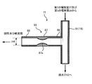
- FIG. 2 is a diagram showing an example of the structure of the miniaturization unit 80.
- the miniaturized part 80 shown in FIG. 2 has a tube structure with an inlet diameter H1, an intermediate trunk diameter H2, and a discharge part diameter H3. That is, the nozzle portion 81 having a truncated cone shape having an inlet diameter H1 and an outlet diameter H2 (H1> H2) and a cylindrical tubular portion 82 having an inner diameter H3 are connected.
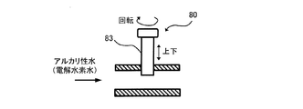
- FIG. 3 is a diagram illustrating another example of the structure of the miniaturization unit 80.
- the miniaturized portion 80 shown in FIG. 3 has a needle valve type structure including a needle valve 83.
- the needle valve 83 moves in the vertical direction, thereby adjusting the flow rate.
- the pressure of flowing water between the electrolytic cell 1 and the micronization unit 80 is not provided with the micronization unit 80. It becomes higher than the pressure of running water (pressure of running water of discharged water). As a result, the amount of hydrogen dissolved in the alkaline water generated in the first electrolysis chamber 25 and the fourth electrolysis chamber 28 of the electrolytic cell 1 increases.
- the pressure of flowing water in the intake channel 17 (pressure of discharged water) when the miniaturization unit 80 is not provided is defined as 0 Mpa.
- the pressure of the flowing water between the electrolytic cell 1 and the micronization unit 80 varies depending on the structure of the micronization unit 80, the flow rate of the raw water flowing through the main raw water supply path 24, etc. In order to increase the amount of dissolved hydrogen, It is 0.01 Mpa or more and 1 Mpa or less, More preferably, it is 0.02 Mpa or more and 0.3 Mpa or less.
- the electromagnetic valve 50 adjusts the flow rate of the acidic water to be drained by controlling the open / closed state by the control of the control unit 5. That is, by restricting the flow rate of the acidic water drained by the electromagnetic valve 50, the pressure of the flowing water between the electrolytic cell 1 and the electromagnetic valve 50 becomes higher than the pressure of the flowing water when the electromagnetic valve 50 is not provided. . Thereby, the 2nd electrolysis chamber 26 and the 3rd electrolysis chamber 27 which are anode chambers are pressurized.
- the reflux solenoid valve 71 adjusts the flow rate of the acidic water flowing through the acidic water branch flow path 70 a by controlling the open / close state by the control of the control unit 5. That is, when the reflux electromagnetic valve 71 restricts the flow rate of the acidic water flowing through the acidic water branch flow path 70a, the pressure between the electrolytic cell 1 and the reflux electromagnetic valve 71 is the same as that when the reflux electromagnetic valve 71 is not provided. It becomes higher than the pressure of running water. Thereby, the 2nd electrolysis chamber 26 and the 3rd electrolysis chamber 27 which are anode chambers are pressurized.
- the dissolved hydrogen concentration can be measured using a known measuring instrument, for example, a portable dissolved hydrogen meter DH-35A manufactured by Toa DKK Corporation.
- the control unit 5 includes a control circuit that controls various functions of the electrolyzed water generating apparatus 100 according to the present embodiment.
- the controller 5 is electrically connected to the flow sensor 51, the first electrode plate 21, the second electrode plate 22, the third electrode plate 23, the electromagnetic valve 50, the return electromagnetic valve 71, and the check valve 72. Yes.
- the flow sensor 51 outputs the detected electrical signal to the control unit 5, and the control unit 5 obtains the water flow rate based on the electrical signal received from the flow sensor 51.
- the controller 5 applies a voltage to the first electrode plate 21, the second electrode plate 22, and the third electrode plate 23 based on a control signal input by a panel operation of the user.
- the panel operation performed by the user refers to an operation of an operation panel (not shown) disposed on the surface of the casing 20 of the electrolyzed water generating apparatus 100.
- the operation panel includes, for example, a power button, an ORP display button, a water flow rate display button, a strong alkaline water supply button, an alkaline water supply button provided for each level from weak alkali to strong alkali, purified water supply button, acidic water supply A button, a sanitary water (strongly acidic water) supply button, a life setting button, a reset button, and the like are provided.
- the operation panel is also provided with a display unit such as a 7-segment LED that displays information such as pH value, ORP value, and water flow rate.
- an alkaline water generating mode for supplying alkaline water a purified water mode for supplying purified water, an acidic water generating mode for supplying acidic water, and a sanitary water generating system for supplying sanitary water are roughly divided. There are four generation modes of mode.
- the power button is a button for starting the electrolyzed water generating apparatus 100, and is an effective button in any state. However, when processing such as drainage is in progress when the power button is pressed, it is preferable that the power is turned off after the processing is completed.
- the ORP display button is a button for displaying the current ORP (redox potential) of water on the 7-segment LED.
- the water flow rate display button is a button for displaying the current water flow rate on the 7-segment LED.
- the alkaline water generation mode includes a strong alkaline water generation mode, a first level alkaline water generation mode, a second level alkaline water generation mode, and a third level alkaline water generation mode in the order of strong alkalinity.
- the second electrode plate 22 and the third electrode plate 23 are set as cathodes and the first electrode plate 21 is set as an anode under the control of the control unit 5 with the electromagnetic valve 50 opened.
- the strong alkaline water supply button is a button for instructing the electrolyzed water generating apparatus 100 to generate strong alkaline water.
- Strong alkaline water for example, has a pH of 10.5, and can be used for boiled food, acupuncture, boiled vegetables, and the like.
- the first level alkaline water supply button is a button for instructing the electrolyzed water generating apparatus 100 to generate the first level alkaline water.
- the first level alkaline water has a pH of 9.5, for example, and can be used for cooking, tea and the like.
- the second level alkaline water supply button is a button for instructing the electrolyzed water generating apparatus 100 to generate the second level alkaline water.
- the second level alkaline water has a pH of 9.0, for example, and can be used for cooking rice or the like.
- the third level alkaline water supply button is a button for instructing the electrolyzed water generating apparatus 100 to generate the third level alkaline water.
- the third level alkaline water has a pH of 8.5, for example, and can be used as drinking water when starting to drink alkaline water.
- the control unit 5 determines the relationship between the levels (first to third levels) of the alkaline water generation mode and the voltages applied to the first electrode plate 21, the second electrode plate 22, and the third electrode plate 23. Is stored.
- the applied voltage is higher in the order of the first level, the second level, and the third level. The higher the applied voltage, the higher the pH of the generated alkaline water and the greater the amount of dissolved hydrogen.
- the purified water supply button is a button for instructing the electrolyzed water generating apparatus 100 to pass water from tap water as it is without generating ionic water.
- no voltage is applied to any of the first electrode plate 21, the second electrode plate 22, and the third electrode plate 23 with the electromagnetic valve 50 closed.
- it can prevent that water is discharged
- the acidic water supply button is a button for instructing the electrolyzed water generating apparatus 100 to generate acidic water.
- Acidic water has a pH of 5.5, for example, and can be used for face washing, boiled noodles, tea astringents and the like.
- the second electrode plate 22 and the third electrode plate 23 are used as the anode and the first electrode plate 21 is used as the cathode under the control of the control unit 5, contrary to the alkaline water generation mode.
- acidic water is taken from the intake channel 17, and alkaline water is drained from the drain channel 18.
- the sanitary water supply button is a button for instructing the electrolyzed water generating apparatus 100 to generate sanitary water.
- Sanitized water has a pH of 2.5, for example.
- the lifetime setting button is a button for setting the lifetime according to the type of cartridge used in the water purification unit 3. For example, when the cartridge used in the water purification unit 3 is replaced with a cartridge different from the cartridge that has been used, the user sets the life by pressing the life setting button. As a result, when the replacement time of the cartridge is approaching, a display informing that the cartridge should be replaced can be displayed on a display unit such as a 7-segment LED.
- the electrolyzed water generating apparatus 100 has a function of integrating the water flow rate and measuring the integrated water flow rate.
- the reset button is a button for resetting the accumulated water flow rate. When the reset button is pressed, an integrated water flow amount counter (not shown) in the control unit 5 is cleared. It should be noted that the reset button is activated by long-pressing for 2 seconds in order to prevent the accumulated water flow rate from being reset accidentally. It is assumed that the reset button is pressed by the user when the cartridge of the water purification unit 3 is replaced.
- the pressed button is lit and the user can visually recognize the type of water supplied from the electrolyzed water generating device 100.
- a temperature increase lamp for notifying the user when a temperature increase in the electrolytic cell 1 occurs is also provided on the operation panel.
- a part of the drainage flowing through the drainage channel 18 can be returned to the second electrolysis chamber 26 and the third electrolysis chamber 27 via the reflux bypass channel 70.
- a part of the acidic water flowing through the drainage channel 18 is returned to the second electrolysis chamber 26 and the third electrolysis chamber 27 which are anode chambers. That is, mixed water of raw water and acidic water is supplied to the second electrolysis chamber 26 and the third electrolysis chamber 27 which are anode chambers.
- the reflux solenoid valve 71 When the alkaline water generation mode is selected, the reflux solenoid valve 71 is controlled so that about half the amount of acidic water flowing through the drainage channel 18 flows into the reflux bypass channel 70. On the other hand, when the water purification mode, the acid water generation mode, and the sanitary water generation mode are selected, the reflux solenoid valve 71 is controlled to a fully closed state. When the return solenoid valve 71 is fully closed, the return via the return bypass passage 70 is not performed.
- the second electrolysis chamber 26 and the third electrolysis chamber 26 which are anode chambers. Due to the large amount of hydrogen ions present in the electrolysis chamber 27, the pH of the water in the first electrolysis chamber 25 and the fourth electrolysis chamber 28 which are the cathode chambers is lowered.
- FIG. 4 is a diagram for explaining that the pH of the water in the fourth electrolysis chamber 28 is lowered by a part of the acidic water flowing through the drainage channel 18 returning to the third electrolysis chamber 27. .
- FIG. 4A is a diagram showing a state before electrolysis of water.
- Water molecules H 2 0
- H + hydrogen ions
- the hydrogen ions contained in the acidic water by reflux are not contained in the third electrolysis chamber 27.
- it is referred to as a hydrogen ion, but actually, it may be present as an oxonium ion such as a hydronium ion.
- FIG. 4B is a diagram showing the state of ions in the third electrolysis chamber 27 and the fourth electrolysis chamber 28 when water is electrolyzed.
- a voltage is applied using the first electrode plate 21 as an anode and the third electrode plate 23 as a cathode, water molecules are electrolyzed, and hydrogen ions (H + ) are generated in the third electrolysis chamber 27 which is an anode chamber.
- hydrogen ions H +
- hydroxide ions OH ⁇
- a part of the acidic water flowing through the drainage channel 18 circulates in the third electrolysis chamber 27 via the reflux bypass channel 70, a part of the acidic water flowing through the drainage channel 18 is not circulated. In comparison, more hydrogen ions are included.
- the diaphragm 12 has a property of transmitting ions. For this reason, in the vicinity of the diaphragm 12, hydrogen ions in the third electrolysis chamber 27 and hydroxide ions in the fourth electrolysis chamber 28 are combined to generate water molecules (H 2 0) ( FIG. 4 (c)).
- H 2 0 water molecules
- the third electrolysis chamber 27 there are many hydrogen ions resulting from the reflux of acidic water, so that the hydroxide ions present in the fourth electrolysis chamber 28 pass through the diaphragm 12. The opportunity to combine with hydrogen ions present in the third electrolysis chamber 27 is increasing.
- hydrogen ions generated by electrolysis of water receive electrons from the third electrode plate 23, which is a cathode, and become hydrogen atoms, which are combined to form hydrogen molecules ( H 2 ) (FIG. 4D). As the hydrogen molecules dissolve in water, electrolytic hydrogen water is generated in the fourth electrolysis chamber 28.
- the electrolyzed water generating apparatus in the present embodiment it is possible to generate alkaline water with suppressed pH increase and high dissolved hydrogen concentration.
- the applied alkaline water is applied to the first electrode plate 21, the second electrode plate 22, and the third electrode plate 23 until the pH of the generated alkaline water exceeds 10.
- the pH is less than 10 suitable for drinking water.
- alkaline water having a high dissolved hydrogen concentration can be produced.
- electrolyzed hydrogen water having a dissolved hydrogen concentration of approximately 800 ppb is obtained by electrolysis at a large current that cannot be realized in a configuration in which acidic water is not refluxed even though it is a first level alkaline water having a pH of 9.5. Can be generated.
- the amount of acidic water discharged from the discharge port 52 is reduced by allowing about half of the amount of acidic water flowing through the drainage channel 18 to flow into the reflux bypass passage 70. It can be reduced in half.
- the amount of raw water flowing into the second electrolysis chamber 26 and the third electrolysis chamber 27 the amount of acidic water to be drained can be reduced, but the electrolysis efficiency is deteriorated.
- the amount of raw water used for electrolysis of water can be reduced.
- the ratio of the raw water flowing through the secondary raw water supply path 24a to the mixed water flowing through the secondary raw water supply path 24b is 19: 1, and half of the acidic water flowing through the drainage path 18 is returned to the secondary raw water supply path 24b, 2.5% of the raw water supplied through the main raw water supply path 24 can be reduced.
- the mixed water of raw water and acidic water flows into the second electrolysis chamber 26 and the third electrolysis chamber 27, the amount of water flowing into the second electrolysis chamber 26 and the third electrolysis chamber 27 is reduced. Therefore, the amount of acidic water to be drained can be reduced while maintaining the electrolytic efficiency.
- the electromagnetic valve 50 restricts the flow rate of the acidic water that is drained, and the reflux solenoid valve 71 restricts the flow rate of the acidic water in the acidic water branch flow path 70a, whereby the anode chamber (the second electrolysis chamber 26 and the second electrolysis chamber 26). 3 electrolysis chamber 27) is pressurized.
- the cathode chamber can be pressurized via the diaphragm 12 of the electrolysis unit 2. That is, the cathode chamber is in a state of being pressurized from the anode chamber side through the diaphragm 12 in addition to the pressurization by the miniaturized portion 80 provided in the intake channel 17, and the dissolved hydrogen concentration in the alkaline water can be further improved. .
- the amount of hydrogen ions moving to the cathode chamber can be increased by pressurizing the anode chamber, hydroxide ions generated in the cathode chamber (the first electrolysis chamber 25 and the fourth electrolysis chamber 28) are increased.
- the opportunity to combine with hydrogen ions can be increased. That is, since the neutralization reaction can be promoted in the cathode chamber, an increase in the pH of alkaline water can be suppressed.
- FIG. 6 is a diagram illustrating a configuration of the electrolyzed water generating apparatus 200 according to the first modification of the embodiment.
- the electrolyzed water generating apparatus 200 shown in FIG. 6 is different from the electrolyzed water generating apparatus 100 shown in FIG.
- the electromagnetic valve 50 is provided on the downstream side of the connection portion with the acidic water branch flow path 70a, and restricts the flow rate of the acidic water to be drained to restrict the second electrolysis chamber 26 and the third electrolysis.
- the chamber 27 is pressurized.
- generation apparatus 200 can further improve the dissolved hydrogen concentration in alkaline water, and can suppress the raise of pH of alkaline water.
- FIG. 7 is a diagram illustrating a configuration of an electrolyzed water generating apparatus 300 according to the second modification of the embodiment.
- the electrolyzed water generating apparatus 300 shown in FIG. 7 is different from the electrolyzed water generating apparatus 100 shown in FIG. 1 in that the electromagnetic valve 50 is not provided.
- the reflux solenoid valve 71 pressurizes the second electrolysis chamber 26 and the third electrolysis chamber 27 by limiting the flow rate of the acidic water flowing through the acidic water branch flow path 70a as described above.
- the electrolyzed water generator 300 can further improve the dissolved hydrogen concentration in the alkaline water, and can suppress an increase in the pH of the alkaline water.
- the inner diameter of the throat portion 87 gradually decreases from the end on the cylindrical portion 86 side toward the minimum diameter portion 87a, and gradually increases from the minimum diameter portion 87a toward the end on the cylindrical portion 88 side. Even in this case, the electromagnetic valve 50 restricts the flow rate of the acidic water to be drained without being controlled by the control unit 5 so that the anode chamber (the second electrolysis chamber 26 and the third electrolysis chamber 27) is provided. Can be pressurized.
- the reflux solenoid valve 71 may have the structure shown in FIG.
- a reflux electromagnetic valve 71 shown in FIG. 10 is substantially T-shaped and includes a main pipe 91 and a branch pipe 93.
- the branch pipe 93 branches from the main pipe 91 and is connected to the acidic water branch flow path 70a.
- the branch pipe 93 has cylindrical portions 86 and 88 and a throat portion 87, and has the same configuration as the electromagnetic valve 50 shown in FIG. Even in this case, the recirculation solenoid valve 71 limits the flow rate of the acidic water flowing through the acidic water branch flow path 70a without being controlled by the control unit 5, and controls the anode chamber (the second electrolysis chamber 26 and the second electrolysis chamber 26). 3 electrolysis chamber 27) can be pressurized.
- the electrolyzed water generating device is provided in the drainage channel 18 or the acidic water branch channel 70a, and restricts the flow rate of the acidic water flowing through the drain channel 18 or the acidic water branch channel 70a to pressurize the anode chamber. What is necessary is just to provide the press part.
- FIG. 5 shows configurations of Comparative Example 1 and Comparative Example 2 that do not include the miniaturization unit 80 among the configurations of Examples 1 and 2 described below and the configuration of the electrolyzed water generating device 100 according to an embodiment.
- the configuration of Comparative Example 3 in which the reflux electromagnetic valve 71 is controlled such that the flow rate of the acidic water that is refluxed via the reflux bypass flow path 70 is zero without the miniaturization unit 80, generated by electrolysis It is a figure shown about the difference etc. of the dissolved hydrogen amount contained in the alkaline water.
- FIG. 1 shows configurations of Comparative Example 1 and Comparative Example 2 that do not include the miniaturization unit 80 among the configurations of Examples 1 and 2 described below and the configuration of the electrolyzed water generating device 100 according to an embodiment.
- the reflux electromagnetic valve 71 is controlled such that the flow rate of the acidic water that is refluxed via the reflux bypass flow path 70 is zero without the miniaturization unit 80, generated by electrolysis It is a figure shown about the difference etc. of the
- the electrolyzed water generating apparatus 100 (see FIG. 1) according to an embodiment is used.
- the miniaturized portion 80 having the structure shown in FIG. 2 is used.
- the pH of the obtained alkaline water is 10.5, and does not satisfy the condition of pH less than 10 suitable for drinking.
- Example 2 in which the total flow rate of raw water supplied from the water pipe 30 with respect to Example 1 was small, the amount of dissolved hydrogen increased and the pH was less than 10 compared to Example 1. Comparing Example 2 and Comparative Example 2 in which the total flow rate of the raw water supplied from the water pipe 30 shows a close value, the amount of dissolved hydrogen is increased by 50% or more in Example 2 having the structure with the micronization unit 80. Moreover, the pH is not so different from that of Comparative Example 2 and is less than 10.
- the drainage channel 18 may function as a water channel so that both alkaline water and acidic water can be taken.
- the reflux bypass flow path 70 is a flow path that connects the drainage path 18 and the secondary raw water supply path 24b, but may be a flow path that connects the drainage path 18 and the main raw water supply path 24.
- part of the acidic water flowing through the drainage channel 18 can be recirculated to the anode chamber, so that the dissolved hydrogen concentration is improved while suppressing an increase in the pH of the alkaline water generated by water electrolysis. Can be made.
Landscapes
- Chemical & Material Sciences (AREA)
- Chemical Kinetics & Catalysis (AREA)
- Electrochemistry (AREA)
- General Chemical & Material Sciences (AREA)
- Life Sciences & Earth Sciences (AREA)
- Hydrology & Water Resources (AREA)
- Engineering & Computer Science (AREA)
- Environmental & Geological Engineering (AREA)
- Water Supply & Treatment (AREA)
- Organic Chemistry (AREA)
- Water Treatment By Electricity Or Magnetism (AREA)
Abstract
【課題】水の電気分解で生成されるアルカリ性水のpHの上昇を抑制しつつ、溶存水素濃度を向上させる。 【解決手段】電解水生成装置100は、陽極室及び陰極室を備え、陽極室及び陰極室に供給される水を電気分解して、酸素が溶存した酸性水を陽極室で生成するとともに、水素が溶存したアルカリ性水を陰極室で生成する電気分解部2と、生成されたアルカリ性水及び酸性水のうちの少なくとも一方を取水するための取水路17と、陽極室に供給される水に、陽極室から吐水される酸性水の一部を合流させるための還流バイパス流路70と、取水路17に設けられる微小化部80とを備える。
Description
本発明は、電解水生成装置に関する。
連続的に電解水を取水可能とした電解槽を具備する電解水生成装置が知られている。その一例として、電解槽内を、陽電極を配設して酸性水を生成する陽極室と、陰電極を配設してアルカリ性水を生成する陰極室とに隔膜を介して区画形成し、陽極室及び陰極室に導水管を連通連結して原水を流入させるとともに、各室に連通連結した取水管より酸性水、アルカリ性水をそれぞれ取水可能としたものがある。かかる構成により、水が陽電極及び陰電極間を通過することで連続的に酸性水及びアルカリ性水を取水することができ、特に健康に良いとされるアルカリ性水については飲用に供されることになる。
また、溶存水素が存在する水(水素水)を飲用すると健康に良いとされる報告があることから、溶存水素濃度を高めたアルカリ性水を取水可能な電解水生成装置が望まれている。溶存水素は、強アルカリ性水ほど多く存在するため、より多くの溶存水素量を確保しようとするとpH値が高くなり、飲用に適するpH10未満のアルカリ性水を得ることができなくなる。このため、特開2009-160503号公報では、生成したアルカリ性水を原水と混和し、pH10未満で溶存水素濃度を高めた水を取水可能な電解水生成装置が提案されている。
しかしながら、特開2009-160503号公報に記載の電解水生成装置では、生成したアルカリ性水を原水と混和するため、水酸化物イオンと共に溶存水素までもが希釈されてしまうこととなり、未だ改善の余地が残されていた。
本願は、pHの上昇を抑制しつつ、溶存水素濃度を高めたアルカリ性水の取水を可能とする技術を開示する。
本願の一実施形態における電解水生成装置は、陽極を有する陽極室及び陰極を有する陰極室を備え、前記陽極室及び前記陰極室に供給される水を電気分解して、酸素が溶存した酸性水を前記陽極室で生成するとともに、水素が溶存したアルカリ性水を前記陰極室で生成する電気分解部と、前記電気分解部で生成されたアルカリ性水及び酸性水のうちの少なくとも一方を取水するための取水路と、前記陽極室に供給される水に、前記陽極室から吐水される酸性水の一部を合流させるための還流バイパス流路と、前記取水路に設けられる微小化部と、を備える。
本実施形態の開示によれば、陽極室へ供給する水に陽極室から吐水された酸性水の一部を合流させるための還流バイパス流路を備えることによって、pHの上昇を抑制しつつ、溶存水素濃度を高めたアルカリ性水を取水することができる。また、微小化部によって、例えば、アルカリ性水に溶存していない水素の気泡を微小化して溶けやすくすることにより、アルカリ性水の溶存水素濃度をさらに向上させることができる。
本発明の一実施形態における電解水生成装置は、陽極を有する陽極室及び陰極を有する陰極室を備え、前記陽極室及び前記陰極室に供給される水を電気分解して、酸素が溶存した酸性水を前記陽極室で生成するとともに、水素が溶存したアルカリ性水を前記陰極室で生成する電気分解部と、前記電気分解部で生成されたアルカリ性水及び酸性水のうちの少なくとも一方を取水するための取水路と、前記陽極室に供給される水に、前記陽極室から吐水される酸性水の一部を合流させるための還流バイパス流路と、前記取水路に設けられる微小化部と、を備える(第1の構成)。
第1の構成によれば、陽極室へ供給する水に陽極室から吐水された酸性水の一部を合流させるための還流バイパス流路を備えることによって、pHの上昇を抑制しつつ、溶存水素濃度を高めたアルカリ性水を取水することができる。また、微小化部によって、例えば、アルカリ性水に溶存していない水素の気泡を微小化して溶けやすくすることにより、アルカリ性水の溶存水素濃度をさらに向上させることができる。
第1の構成において、前記微小化部は、前記取水路に流れるアルカリ性水に溶存していない水素の気泡の少なくとも一部を1ミリメートル未満の大きさに微小化するようにしても良い(第2の構成)。
第2の構成によれば、アルカリ性水に溶存していない水素の気泡を1ミリメートル未満の大きさに微小化して溶けやすくするので、アルカリ性水の溶存水素濃度をさらに向上させることができる。
第1または第2の構成において、前記電気分解部で水を電気分解している際に、前記電気分解部と前記微小化部との間の流水の圧力は、前記微小化部が設けられていない場合の流水の圧力と比べて高い構成としても良い(第3の構成)。
第3の構成によれば、微小化部を設けない構成と比べて、電気分解部と微小化部との間の流水の圧力が上昇するので、電気分解部による電気分解によって生成されたアルカリ性水に溶存する水素量をさらに増大させることができる。
第3の構成において、前記微小化部が設けられていない場合の前記取水路の流水の圧力を0Mpaとすると、前記電気分解部で水を電気分解している際に、前記電気分解部と前記微小化部との間の流水の圧力は0.01MPa以上1MPa以下としても良い(第4の構成)。
第4の構成によれば、微小化部を設けて、電気分解部と微小化部との間の流水の圧力を0.01MPa以上1MPa以下とすることにより、取水するアルカリ性水に溶存する水素を増大させることができるので、アルカリ性水の溶存水素濃度を向上させることができる。
第1から第4のいずれかの構成において、前記取水路は、アルカリ性水を取水し、前記電解水生成装置は、前記陽極室から吐水された酸性水を排水する排水路をさらに備え、前記還流バイパス流路は、前記排水路の中途より酸性水の一部を分流する酸性水分岐流路と、前記陽極室に水を供給する供給路上に形成され、前記酸性水分岐流路を流れる酸性水を前記陽極室に供給される水に合流させる酸性水還流混合部と、を備える構成としても良い(第5の構成)。
第5の構成によれば、排水となる酸性水の量を低減させつつ、酸性水を陽極室に還流させることができる。
第5の構成において、前記排水路または前記酸性水分岐流路に設けられ、当該排水路または当該酸性水分岐流路を流れる酸性水の流量を制限して前記陽極室を加圧する制限加圧部をさらに備える構成としても良い(第6の構成)。
第6の構成によれば、陽極室を加圧することにより、陰極室が加圧される。陰極室は、取水路に設けられた微小化部による加圧に加え、陽極室側からも加圧されることにより、アルカリ性水に溶存する水素をさらに増大させることができる。また、陽極室を加圧することにより水素イオンと水酸化物イオンとの中和反応が促進されるため、アルカリ性水のpHの上昇を抑制することができる。
第6の構成において、前記制限加圧部は、前記酸性水分岐流路に設けられ、当該酸性水分岐流路を流れる酸性水の流量を調整する還流水量調整部を含む構成としても良い(第7の構成)。
第7の構成によれば、還流させる酸性水の流量を調整することによって、生成されるアルカリ性水のpHを調整することができる。
第6の構成において、前記制限加圧部は、前記排水路の中途であって、前記酸性水分岐流路との接続部よりも下流に設けられ、排水する酸性水の流量を調整する排水量調整部を含む構成としても良い(第8の構成)。
第8の構成によれば、排水する酸性水の流量を調整することによって、還流させる酸性水の流量を調整することができるので、生成されるアルカリ性水のpHを調整することができる。
第5の構成において、前記酸性水分岐流路に設けられ、当該酸性水分岐流路を流れる酸性水の流量を調整する還流水量調整部をさらに備えるようにしても良い(第9の構成)。
第9の構成によれば、還流させる酸性水の流量を調整することによって、生成されるアルカリ性水のpHを調整することができる。
第5または第9の構成において、前記排水路の中途であって、前記酸性水分岐流路との接続部よりも下流側に設けられ、排水する酸性水の流量を調整する排水量調整部をさらに備えるようにしても良い(第10の構成)。
第10の構成によれば、排水する酸性水の流量を調整することによって、還流させる酸性水の流量を調整することができるので、生成されるアルカリ性水のpHを調整することができる。
第1から第10のいずれかの構成において、前記微小化部は、前記アルカリ性水に溶存していない水素の気泡の少なくとも一部を、1マイクロメートル以上1ミリメートル未満の大きさ、及び、1ナノメートル以上1マイクロメートル未満の大きさの少なくとも一方の大きさに微小化するようにしても良い(第11の構成)。
第8の構成によれば、アルカリ性水に溶存していない水素の気泡の少なくとも一部をマイクロバブル化、及びナノバブル化の少なくとも一方とすることにより、水に溶けやすい状態として、溶存水素濃度を向上させることができる。
[実施の形態]
以下、図面を参照し、本発明の実施の形態を詳しく説明する。図中同一または相当部分には同一符号を付してその説明は繰り返さない。なお、説明を分かりやすくするために、以下で参照する図面においては、構成が簡略化または模式化して示されたり、一部の構成部材が省略されたりしている。また、各図に示された構成部材間の寸法比は、必ずしも実際の寸法比を示すものではない。
以下、図面を参照し、本発明の実施の形態を詳しく説明する。図中同一または相当部分には同一符号を付してその説明は繰り返さない。なお、説明を分かりやすくするために、以下で参照する図面においては、構成が簡略化または模式化して示されたり、一部の構成部材が省略されたりしている。また、各図に示された構成部材間の寸法比は、必ずしも実際の寸法比を示すものではない。
図1は、一実施形態における電解水生成装置100の構成を示す図である。電解水生成装置100は、電気分解部2と、浄水部3と、添加部4と、制御部5と、微小化部80とを備える。電気分解部2、浄水部3、添加部4、及び制御部5は、略箱型としたケーシング20内に収納配設されている。
電気分解部2は、電解槽1と、電解槽1の周囲に配設された流路配管等により構成されている。
電解槽1には、水道管30から水道蛇口31を介して原水(水道水)が供給される。原水は、pH7程度の中性水である。ただし、電解槽1に供給する原水は、極端なpH調整が行われていないpH6~8程度の飲用可能な水であれば水道水に限定されることはない。水道蛇口31には、分岐栓32が配設されている。分岐栓32は給水ホース33の一方と接続されており、給水ホース33の他方は、浄水部3の流入口と接続されている。
浄水部3は、水道管30から供給される原水(水道水)を浄化する機能を有する。具体的には、浄水部3は、活性炭などの多孔質部材を有することにより、水道管30から供給される原水(水道水)に含まれる夾雑物を吸着する吸着手段として機能する。また、浄水部3は、金属メッシュや布材、ろ紙等の比較的粗いフィルタを備えるとともに、雑菌等までも除去可能な中空糸膜等を備えた濾過手段として機能する。
浄水部3の流出口は、流量センサ51の流入口と接続されている。流量センサ51は、流水量を測定可能に構成され、例えば、その中央部にプロペラを備え、プロペラの回転数により流水量を測定する。流量センサ51の流出口は、添加部4の流入口と接続されている。
添加部4には、浄水部3による浄化後の浄水にカルシウムを添加するためのカルシウム剤が収容されている。カルシウム剤には、乳酸カルシウムやグリセロリン酸カルシウム等が含まれており、カルシウム剤に浄水を接触させてカルシウムを溶出させることで、電解物質の少ない水を電気分解しやすくする。
添加部4の流出口は、主原水供給路24と接続されている。主原水供給路24は、中途で副原水供給路24a及び副原水供給路24bに分岐している。副原水供給路24aは、後述する電解槽1の第1の電解室25及び第4の電解室28の流入口に接続され、副原水供給路24bは、後述する電解槽1の第2の電解室26及び第3の電解室27の流入口に接続されている。
電解槽1には、陽極及び陰極が設けられ、陽極及び陰極間に電圧を印加することにより、電解槽1内の原水が電気分解される。原水を電気分解すると、陽極側からは酸性水が生成されるとともに、酸素が発生し、陰極側からはアルカリ性水が生成されるとともに、水素が発生する。
電解槽1は、中央に位置する第1の電極板21と、第1の電極板21を挟み込むように位置する第2の電極板22及び第3の電極板23とを備えている。第1の電極板21、第2の電極板22、及び第3の電極板23として、例えば、チタン表面を白金で覆った白金被覆チタンを用いることができる。
第1の電極板21と第2の電極板22との間、及び、第1の電極板21と第3の電極板23との間にはそれぞれ、隔膜12が配設されている。電解槽1には、第1の電極板21、第2の電極板22、第3の電極板23、及び隔膜12により、第1の電解室25、第2の電解室26、第3の電解室27、及び第4の電解室28が区画形成されている。
第2の電極板22と第3の電極板23は、ケーシング20に配設された制御部5に設けた電源回路(図示せず)からの電力の供給を受け、陰極又は陽極の同一極の電極板となる一方、第1の電極板21は、第2の電極板22及び第3の電極板23の極性とは逆の極性の電極板となる。
ここでは、第2の電極板22及び第3の電極板23を陰極とし、第1の電極板21を陽極とする。従って、第1の電解室25及び第4の電解室28は陰極室となってアルカリ性水(電解水素水)が生成され、第2の電解室26及び第3の電解室27は陽極室となって酸性水が生成される。すなわち、第1の電解室25及び第4の電解室28はアルカリ性水生成室となり、第2の電解室26及び第3の電解室27は酸性水生成室となる。
各電解室25、26、27、28には、水の流入口と流出口が設けられている。第1の電解室25と第4の電解室28の各流出口に連通した流路は互いに合流して、取水路17を形成する。取水路17からは、所望するpHのアルカリ性水を取水することができる。一方、第2の電解室26と第3の電解室27の各流出口に連通した流路は互いに合流して、排水路18を形成する。排水路18を流れる酸性水は、電磁弁50を介して排水可能である。
電磁弁50は、排水路18の中途であって、後述する酸性水分岐流路70aとの接続部よりも下流側に設けられ、排水する酸性水の流量を調整する排水量調整部として機能する。図1に示す例では、電磁弁50は、排出口52の近傍に設けられている。
第1の電極板21、第2の電極板22、及び第3の電極板23の極性はそれぞれ反転させることができる。極性を反転させると、第2の電極板22及び第3の電極板23は陽極となり、第1の電極板21は陰極となるので、第1の電解室25及び第4の電解室28が陽極室(酸性水生成室)となり、第2の電解室26及び第3の電解室27が陰極室(アルカリ性水生成室)となる。この場合、取水路17からは酸性水が取水され、排水路18からはアルカリ性水が排水される。
上述した副原水供給路24bは、逆止弁72を介して排水路18と接続されている。逆止弁72は、常時、排水路18から副原水供給路24bの方向への水の流れを止める役割を有している。通水時の水圧がある場合、逆止弁72は、副原水供給路24bから排水路18の方向への水の流れをも止め、通水時の水圧が無い場合には、各電解室25,26,27,28や各流路に溜まった水を排水路18へ流すように制御される。
本実施形態では、陽極室に供給される原水に、陽極室から吐水される酸性水の一部を合流させるための還流バイパス流路70が設けられている。還流バイパス流路70は、陽極室から吐水された酸性水を排水する排水路18の中途より酸性水の一部を分流する酸性水分岐流路70aと、陽極室に水を供給する副原水供給路24b上に形成され、酸性水分岐流路70aを流れる酸性水を陽極室に供給される原水に合流させる酸性水還流混合部70bとを備える。
すなわち、本実施形態では、取水路17からアルカリ性水を取水する場合に、排水路18を流れる酸性水の一部を、陽極室である第2の電解室26及び第3の電解室27に還流させる。従って、陽極室である第2の電解室26及び第3の電解室27には、原水と酸性水の混合水が供給される。
酸性水分岐流路70aを介して還流させる酸性水の量は、還流電磁弁71によって調整することができる。すなわち、還流電磁弁71は、酸性水分岐流路70aを流れる酸性水の流量を調整する還流水量調整部として機能する。還流電磁弁71は、制御部5と電気的に接続されており、制御部5によって開閉状態が制御される。還流電磁弁71は、排水路18と酸性水分岐流路70aとの接続部分に設けられている。ただし、排水路18から酸性水分岐流路70aへの分流割合や、陽極室に供給される原水への酸性水の混合量を調整できるのであれば、還流電磁弁71が設けられる位置は、酸性水分岐流路70aと排水路18との接続部分に限定されることはなく、酸性水分岐流路70aの任意の位置とすることができる。
本実施形態では、副原水供給路24aを経て第1の電解室25及び第4の電解室28に流入する水の流量と、副原水供給路24bを経て第2の電解室26及び第3の電解室27に流入する水の流量とは19:1となるように設定されている。副原水供給路24bを経て第2の電解室26及び第3の電解室27に流入する水は、主原水供給路24から供給される原水と、還流バイパス流路70を介して還流される酸性水との混合水である。ただし、流量の比が19:1に限定されることはない。
微小化部80は、取水路17の途中に配置されている。微小化部80は、取水路17を流れるアルカリ性水(電解水素水)に溶存していない水素の気泡の少なくとも一部を1ミリメートル未満の大きさの気泡に微小化して、アルカリ性水中の溶存水素濃度を向上させるための装置である。すなわち、電気分解で生成されたアルカリ性水には、溶存せずに気泡となっている水素が含まれているが、微小化部80は、アルカリ性水に溶存しないで気泡化した水素の少なくとも一部を、より微小な気泡からなる水素へとマイクロバブル化、ナノバブル(ウルトラファインバブル)化、ファインバブル化する。本明細書において、マイクロバブルは、1マイクロメートル以上1ミリメートル未満のマイクロメートルサイズの気泡、ナノバブル(ウルトラファインバブル)は、1ナノメートル以上1マイクロメートル未満のナノメートルサイズの気泡、ファインバブルは、マイクロバブルやナノバブルが混在した状態の気泡である。
一般的に、ファインバブル等の微小なバブルを生成するためには、十分な水量・水圧を必要とする。一般的な家庭用水道の蛇口の径(1cm程度)の場合、水量で言えば、例えば5L/分程度の水量を蛇口から送水できる。アルカリイオン整水器のように、電気分解により水素を発生させる機器の場合、アルカリイオン整水器内の浄水ユニット(浄水部)や電気分解槽(電界槽)を含む流路による抵抗等により、アルカリイオン整水器から取水する際は、2~3L/分程度と、家庭用の水道水を直接取水するよりも水量が少なくなる。微小化部80は、上記のように水量が小さい条件でも、アルカリ性水に溶存しないで気泡化した水素を1ミリメートル未満の大きさの気泡に微小化する。
マイクロバブルやナノバブルは、1ミリメートル以上の大きさの気泡に比べて、水中での滞在時間が長く、水に溶けやすいという特徴がある。従って、アルカリ性水に溶存していない水素の気泡をマイクロバブル化、ナノバブル(ウルトラファインバブル)化、ファインバブル化して、1ミリメートル未満の大きさに微小化することにより、アルカリ性水の溶存水素量を増大させることができる。
アルカリ性水に溶存しないで気泡化した水素を、より微小な気泡からなる水素へとマイクロバブル化、ナノバブル(ウルトラファインバブル)化、ファインバブル化する方法としては既知の方法、例えば、旋回流方式、超微細孔方式、キャビテーション方式、ベンチュリー方式、エジェクター方式、せん断方式、超音波振動方式、加圧溶解方式、スタティックミキサー方式等がある。
旋回流方式では、電解槽1の第1の電解室25及び第4の電解室28で生成されたアルカリ性水が旋回流方式の微小化部80内に流入することによって旋回流が起こり、溶存していない水素の気泡のマイクロバブル化、ナノバブル(ウルトラファインバブル)化、ファインバブル化が生じる。
超微細孔方式では、電解槽1の第1の電解室25及び第4の電解室28で生成されたアルカリ性水が超微細孔方式の微小化部80内に流入することで、溶存していない水素の気泡のマイクロバブル化、ナノバブル(ウルトラファインバブル)化、ファインバブル化が生じる。
キャビテーション方式では、微小化部80はキャビテーションを発生させるための構造を備え、流路の急激な拡大や障害物等によって負圧が生じてキャビテーションが発生し、溶存していない水素の気泡のマイクロバブル化、ナノバブル(ウルトラファインバブル)化、ファインバブル化が生じる。
ベンチュリー方式では、微小化部80はベンチュリー管を備え、ベンチュリー管内で生じる気泡の微細化現象を利用して、溶存していない水素の気泡をマイクロバブル化、ナノバブル(ウルトラファインバブル)化、ファインバブル化する。
エジェクター方式では、微小化部80は、流路の狭い狭小部及び流路の広い拡大部を備え、狭小部を通過したアルカリ性水が拡大部で渦流れを発生し、強い剪断場を形成して、溶存していない水素の気泡がマイクロバブル化、ナノバブル(ウルトラファインバブル)化、ファインバブル化する。
せん断方式では、微小化部80はスクリューを備え、スクリューの羽根の回転により、溶存していない水素の気泡をせん断することによって、マイクロバブル化、ナノバブル(ウルトラファインバブル)化、ファインバブル化が生じる。
超音波振動方式では、超音波の圧力変動によって、溶存していない水素の気泡を擾乱することにより、マイクロバブル化、ナノバブル(ウルトラファインバブル)化、ファインバブル化を生じさせる。
加圧溶解方式では、微小化部80は、圧力を高めた加圧ユニット、及びベンチュリー管構造のような減圧ノズル部を備える。まず、アルカリ性水を加圧ユニット内に流入させることにより、溶存していない水素は気液界面を通して水に溶解する。加圧ユニット内は圧力が高く、飽和溶存水素濃度も高いため、加圧ユニットの流出口から溶存水素濃度の高いアルカリ性水が吐出される。その後、ベンチュリー管構造のような減圧ノズル部にアルカリ性水を流入させることにより、急激な圧力低下が発生し、飽和溶存水素濃度が低下するため、アルカリ性水に溶けきれなくなった水素が発泡して、マイクロバブル化、ナノバブル(ウルトラファインバブル)化、ファインバブル化が生じる。
スタティックミキサー方式では、微小化部80は、内部に強い旋回流を発生させるガイドベーンまたはスクリューと、内壁に突起列を有するノズルとを有し、ノズルに流入した水素の泡を含むアルカリ性水(または水素が高濃度に加圧溶解したアルカリ性水)は、強い剪断力と大きな負圧によるキャビテーション及び衝撃波等により、マイクロバブル、ナノバブル(ウルトラファインバブル)、ファインバブルを生成する。
図2は、微小化部80の一つの構造例を示す図である。図2に示す微小化部80は、入口径H1、中間胴径H2、吐出部径H3の管構造を有する。すなわち、入口径H1及び出口径H2(H1>H2)の円錐台形状のノズル部81と、内径がH3の円筒形状の筒状部82とが接続された構造となっている。
図3は、微小化部80の別の構造例を示す図である。図3に示す微小化部80は、ニードルバルブ83を備えたニードルバルブ方式の構造である。この構造では、ニードルバルブ83を回転させると、ニードルバルブ83が上下方向に移動し、これにより流量を調整する。
本実施形態における電解水生成装置100では、取水路17に微小化部80を設けることによって、電解槽1と微小化部80との間の流水の圧力は、微小化部80を設けていない場合の流水の圧力(吐水の流水の圧力)よりも高くなる。これにより、電解槽1の第1の電解室25及び第4の電解室28で生成されたアルカリ性水に溶存する水素量が増大する。
本実施形態では、微小化部80が設けられていない場合の取水路17の流水の圧力(吐水の流水の圧力)を0Mpaと定義する。電解槽1と微小化部80との間の流水の圧力は、微小化部80の構造や、主原水供給路24を流れる原水の流量等によって変わるが、溶存水素量の増大のためには、0.01Mpa以上1Mpa以下、より好ましくは0.02Mpa以上0.3Mpa以下である。
また、本実施形態における電解水生成装置100では、電磁弁50は、制御部5による制御によって開閉状態を制御することによって、排水する酸性水の流量を調整する。つまり、電磁弁50が排水する酸性水の流量を制限することにより、電解槽1と電磁弁50との間の流水の圧力は、電磁弁50を設けていない場合の流水の圧力よりも高くなる。これにより、陽極室である第2の電解室26及び第3の電解室27が加圧される。
また、還流電磁弁71は、制御部5による制御によって開閉状態を制御することによって、酸性水分岐流路70aを流れる酸性水の流量を調整する。つまり、還流電磁弁71が酸性水分岐流路70aを流れる酸性水の流量を制限することにより、電解槽1と還流電磁弁71との間の圧力は、還流電磁弁71を設けていない場合の流水の圧力よりも高くなる。これにより、陽極室である第2の電解室26及び第3の電解室27が加圧される。
なお、溶存水素濃度は、既知の計測器、例えば東亜ディーケーケー株式会社のポータブル溶存水素計DH-35Aを用いて計測することができる。
制御部5は、本実施形態における電解水生成装置100の機能を各種制御する制御回路を備えている。制御部5は、流量センサ51、第1の電極板21、第2の電極板22、第3の電極板23、電磁弁50、還流電磁弁71、逆止弁72と電気的に接続されている。流量センサ51は、検出した電気信号を制御部5に出力し、制御部5は、流量センサ51から受信した電気信号に基づいて、通水量を求める。
制御部5は、使用者のパネル操作により入力される制御信号に基づいて、第1の電極板21、第2の電極板22、及び第3の電極板23に電圧を印加する。なお、使用者が行うパネル操作とは、電解水生成装置100のケーシング20の表面に配設された操作パネル(図示せず)の操作を指す。
操作パネルには、例えば、電源ボタン、ORP表示ボタン、通水量表示ボタン、強アルカリ性水供給ボタン、弱アルカリから強アルカリまでのレベル毎に設けられたアルカリ性水供給ボタン、浄水供給ボタン、酸性水供給ボタン、衛生水(強酸性水)供給ボタン、寿命設定ボタン、リセットボタン等が設けられている。操作パネルにはまた、pH値、ORP値、通水量等の情報を表示する7セグメントLED等の表示部等も設けられている。
本実施形態における電解水生成装置100では、大きく分けて、アルカリ性水を供給するアルカリ性水生成モード、浄水を供給する浄水モード、酸性水を供給する酸性水生成モード、衛生水を供給する衛生水生成モードの4つの生成モードがある。
電源ボタンは、電解水生成装置100を起動させるためのボタンであり、どのような状態であっても有効なボタンである。ただし、電源ボタンの押下時に、排水処理等の処理が途中である場合には、それらの処理が終了してから電源が落ちるようにすることが好ましい。
ORP表示ボタンは、7セグメントLEDに、現在の水のORP(酸化還元電位)を表示させるためのボタンである。通水量表示ボタンは、7セグメントLEDに、現在の水の通水量を表示させるためのボタンである。
アルカリ性水生成モードには、アルカリ性の強い順に、強アルカリ性水生成モード、第1レベルのアルカリ性水生成モード、第2レベルのアルカリ性水生成モード、第3レベルのアルカリ性水生成モードがある。アルカリ性水生成モードでは、電磁弁50が開いた状態で、制御部5の制御により、第2の電極板22及び第3の電極板23を陰極とし、第1の電極板21を陽極とする。
強アルカリ性水供給ボタンは、電解水生成装置100に、強アルカリ性水の生成を指示するためのボタンである。強アルカリ性水は、例えば、pH10.5であり、煮物、アク抜き、野菜ゆで等に使用することができる。
第1レベルのアルカリ性水供給ボタンは、電解水生成装置100に、第1レベルのアルカリ性水の生成を指示するためのボタンである。第1レベルのアルカリ性水は、例えば、pH9.5であり、料理、お茶等に使用することができる。第2レベルのアルカリ性水供給ボタンは、電解水生成装置100に、第2レベルのアルカリ性水の生成を指示するためのボタンである。第2レベルのアルカリ性水は、例えば、pH9.0であり、炊飯等に使用することができる。第3レベルのアルカリ性水供給ボタンは、電解水生成装置100に、第3レベルのアルカリ性水の生成を指示するためのボタンである。第3レベルのアルカリ性水は、例えば、pH8.5であり、アルカリ性水を飲み始める際の飲用水等として使用することができる。
制御部5は、アルカリ性水生成モードの各レベル(第1~第3レベル)と、第1の電極板21、第2の電極板22、及び第3の電極板23への印加電圧との関係を定めたテーブルデータを記憶している。印加電圧は、第1レベル、第2レベル、第3レベルの順に高く、印加電圧が高いほど、生成されるアルカリ性水のpHは高くなり、溶存水素量は多くなる。
浄水供給ボタンは、電解水生成装置100に、イオン水を生成することなく水道水からの水をそのまま通水させることを指示するためのボタンである。浄水モードでは、電磁弁50を閉じた状態で、第1の電極板21、第2の電極板22、及び第3の電極板23のいずれにも電圧を印加しない。なお、電磁弁50を閉じることで、排出口52から水が排出されるのを防ぐことができる。
酸性水供給ボタンは、電解水生成装置100に酸性水の生成を指示するためのボタンである。酸性水は、例えば、pH5.5であり、洗顔、麺ゆで、茶渋とり等に使用することができる。酸性水生成モードでは、アルカリ性水生成モードとは逆で、制御部5の制御によって、第2の電極板22及び第3の電極板23を陽極とし、第1の電極板21を陰極とする。これにより、取水路17からは酸性水が取水され、排水路18からはアルカリ性水が排水される。
衛生水供給ボタンは、電解水生成装置100に、衛生水の生成を指示するためのボタンである。衛生水は、例えば、pH2.5である。
寿命設定ボタンは、浄水部3に用いられるカートリッジの種類に応じた寿命を設定するためのボタンである。例えば、浄水部3に用いられるカートリッジを、それまで使用してきたカートリッジと異なるカートリッジに交換した場合、ユーザは、寿命設定ボタンを押下することによって寿命を設定する。これにより、カートリッジの交換時期が近づいてくると、7セグメントLED等の表示部に、カートリッジを交換すべきことを知らせる表示を行うことができる。
電解水生成装置100は、通水量を積算して、積算通水量を計測する機能を有している。リセットボタンは、積算通水量をリセットするためのボタンである。リセットボタンが押下されると、制御部5に内在する積算通水量カウンタ(不図示)がクリアされる。なお、リセットボタンは、誤って押下されて積算通水量がリセットされるのを防止するために、2秒長押しで有効となる。リセットボタンは、浄水部3のカートリッジが交換された場合に、使用者によって押下されることを想定している。
強アルカリ性水供給ボタン、第1レベルのアルカリ性水供給ボタン、第2レベルのアルカリ性水供給ボタン、第3レベルのアルカリ性水供給ボタン、浄水供給ボタン、酸性水供給ボタン、衛生水供給ボタンが使用者によって押下されると、押下されたボタンが点灯して、電解水生成装置100から供給される水の種類を使用者が視認可能となっている。この他、電解槽1内の温度上昇が生じた場合に、使用者に知らせるための温度上昇ランプ等も操作パネル上に配設されている。
上述したように、排水路18を流れる排水の一部は、還流バイパス流路70を介して第2の電解室26及び第3の電解室27に還流させることができる。本実施形態では、アルカリ性水生成モードの選択時に、排水路18を流れる酸性水の一部を、陽極室である第2の電解室26及び第3の電解室27に還流させる。すなわち、陽極室である第2の電解室26及び第3の電解室27には、原水と酸性水の混合水が供給される。
アルカリ性水生成モードの選択時に、還流電磁弁71は、排水路18を流れる酸性水の約1/2の量が還流バイパス流路70に流れるように制御される。一方、浄水モード、酸性水生成モード、及び衛生水生成モードの選択時には、還流電磁弁71は、全閉状態に制御される。還流電磁弁71が全閉の状態では、還流バイパス流路70を介した還流は行われない。
アルカリ性水生成モードの選択時に、排水路18を流れる酸性水の一部が第2の電解室26及び第3の電解室27に還流すると、陽極室である第2の電解室26及び第3の電解室27に存在する多量の水素イオンによって、陰極室である第1の電解室25及び第4の電解室28内の水のpHが低下する。
図4は、排水路18を流れる酸性水の一部が第3の電解室27に還流することによって、第4の電解室28内の水のpHが低下することを説明するための図である。なお、排水路18を流れる酸性水の一部が第2の電解室26に還流することによって、第1の電解室25内の水のpHが低下する原理についても同様である。
図4(a)は水の電気分解を行う前の状態を示す図である。第3の電解室27及び第4の電解室28には水分子(H20)が存在する。また、第3の電解室27には、前回の水の電気分解時に、還流バイパス流路70を介して還流した酸性水が流入しているため、水分子とともに水素イオン(H+)が存在する。ただし、水の電気分解を初めて行う場合には、還流による酸性水に含まれている水素イオンは、第3の電解室27には含まれていない。なお、ここでは説明の便宜上水素イオンと称するが、実際はヒドロニウムイオンなどのオキソニウムイオンとして存在する場合も考えられる。
図4(b)は、水の電気分解を行っているときの第3の電解室27及び第4の電解室28内のイオンの状態を示す図である。第1の電極板21を陽極、第3の電極板23を陰極として電圧を印加すると、水分子が電気分解されて、陽極室である第3の電解室27には水素イオン(H+)が発生し、陰極室である第4の電解室28には水酸化物イオン(OH-)が発生する。また、第3の電解室27には、還流バイパス流路70を介して、排水路18を流れる酸性水の一部が還流するので、排水路18を流れる酸性水の一部を還流させない構成と比べて、より多くの水素イオンが含まれる状態となる。
隔膜12はイオンを透過する性質を有する。このため、隔膜12の近傍では、第3の電解室27内の水素イオンと、第4の電解室28内の水酸化物イオンが結合して、水分子(H20)が生成される(図4(c))。ここで、第3の電解室27には、酸性水の還流に起因する多くの水素イオンが存在することから、第4の電解室28内に存在する水酸化物イオンは、隔膜12を介して、第3の電解室27に存在する水素イオンと結合する機会が増えている。これにより、酸性水を還流させる本実施形態の構成では、隔膜12の近傍において中和反応が促進されるので、酸性水を還流させない構成と比べて、水酸化物イオンがより多く低減して、第4の電解室28内の水のpHが低下する。
また、第4の電解室28内では、水の電気分解によって生成された水素イオンが陰極である第3の電極板23から電子を受け取って水素原子となり、それが2つ結合して水素分子(H2)となる(図4(d))。この水素分子が水に溶解することにより、第4の電解室28内では、電解水素水が生成される。
すなわち、本実施形態における電解水生成装置によれば、pH上昇が抑制され、かつ、溶存水素濃度の高いアルカリ性水を生成することができる。例えば、酸性水を還流させない構成であれば生成されるアルカリ性水のpHが10を上回るレベルの電圧まで第1の電極板21、第2の電極板22、及び第3の電極板23への印加電圧を上げて水の電気分解を行い、排水路18を流れる酸性水の一部を第2の電解室26及び第3の電解室27に還流させることによって、pHが飲用水に適した10未満であって、かつ溶存水素濃度が高いアルカリ性水を生成することができる。これにより、pH9.5の第1レベルのアルカリ性水でありながら、酸性水を還流させない構成では実現し得なかった大電流での電気分解により、溶存水素濃度が略800ppbも含まれる電解水素水を生成することができる。
また、アルカリ性水生成モードの選択時に、排水路18を流れる酸性水の約1/2の量が還流バイパス流路70に流れるようにすることにより、排出口52から排水される酸性水の量を半分に低減することができる。なお、第2の電解室26及び第3の電解室27に流入させる原水の量を減らすことにより、排水される酸性水の量を減らすことができるが、電解効率が悪化してしまう。
また、排水路18を流れる酸性水の一部を副原水供給路24bに還流させることにより、水の電気分解のために使用する原水の使用量も低減することができる。副原水供給路24aを流れる原水と副原水供給路24bを流れる混合水の比率を19:1とし、排水路18を流れる酸性水の1/2を副原水供給路24bに還流させる場合には、主原水供給路24を介して供給する原水の2.5%を削減することができる。この場合、第2の電解室26及び第3の電解室27には、原水と酸性水の混合水が流入するため、第2の電解室26及び第3の電解室27に流入させる水量を減らすことなく電解効率は維持したままで、排水する酸性水の量を減らすことができる。
また、電磁弁50が排水される酸性水の流量を制限し、還流電磁弁71が酸性水分岐流路70aにおける酸性水の流量を制限することにより、陽極室(第2の電解室26及び第3の電解室27)を加圧する。陽極室を加圧することにより、電気分解部2の隔膜12を介して陰極室を加圧することができる。すなわち陰極室は、取水路17に設けた微小化部80による加圧に加え、隔膜12を介して陽極室側から加圧される状態となり、アルカリ性水における溶存水素濃度をさらに向上させることができる。また、陽極室の加圧により、陰極室に移動する水素イオンの量を増加させることができるため、陰極室(第1の電解室25及び第4の電解室28)で発生する水酸化物イオンが、水素イオンと結合する機会を増やすことができる。つまり、陰極室において中和反応を促進させることができるため、アルカリ性水のpHの上昇を抑制することができる。
[変形例1]
上記実施の形態では、電解水生成装置100が、排水量調整部としての電磁弁50と、還流水量調整部としての還流電磁弁71との両者を備える例を説明したが、これに限られない。
上記実施の形態では、電解水生成装置100が、排水量調整部としての電磁弁50と、還流水量調整部としての還流電磁弁71との両者を備える例を説明したが、これに限られない。
図6は、上記実施形態の変形例1に係る電解水生成装置200の構成を示す図である。図6に示す電解水生成装置200は、還流電磁弁71を備えていない点が図1に示す電解水生成装置100と異なる。
電磁弁50は、上述のように、酸性水分岐流路70aとの接続部よりも下流側に設けられ、排水される酸性水の流量を制限して第2の電解室26及び第3の電解室27を加圧する。これにより、電解水生成装置200は、アルカリ性水における溶存水素濃度をさらに向上させることができ、アルカリ性水のpHの上昇を抑制することができる。
[変形例2]
図7は、上記実施形態の変形例2に係る電解水生成装置300の構成を示す図である。図7に示す電解水生成装置300は、電磁弁50を備えていない点が図1に示す電解水生成装置100と異なる。
図7は、上記実施形態の変形例2に係る電解水生成装置300の構成を示す図である。図7に示す電解水生成装置300は、電磁弁50を備えていない点が図1に示す電解水生成装置100と異なる。
還流電磁弁71は、上述のように、酸性水分岐流路70aを流れる酸性水の流量を制限して第2の電解室26及び第3の電解室27を加圧する。電解水生成装置300は、アルカリ性水における溶存水素濃度をさらに向上させることができ、アルカリ性水のpHの上昇を抑制することができる。
[その他の変形例]
上記実施の形態では、電磁弁50及び還流電磁弁71の各々の開閉が、制御部5によって制御される例を説明したが、これに限られない。電磁弁50及び還流電磁弁71の各々は、制御部5によって制御されなくてもよい。
上記実施の形態では、電磁弁50及び還流電磁弁71の各々の開閉が、制御部5によって制御される例を説明したが、これに限られない。電磁弁50及び還流電磁弁71の各々は、制御部5によって制御されなくてもよい。
例えば、電磁弁50は、図2に示す微小化部80と同様の構成を有するベンチュリー管であってもよい。この場合、電磁弁50は、制御部5による制御を受けることなく、排水する酸性水の流量を制限して第2の電解室26及び第3の電解室27を加圧することができる。
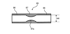
また、電磁弁50は、図8に示す構造を有していてもよい。図8に示す電磁弁50は、筒状部86,88と、スロート部87とを有する。筒状部86は、電磁弁50の入口に配置され、筒状部88は、電磁弁50の出口に配置される。スロート部87は、筒状部86と筒状部88との間に配置される。スロート部87の内径は、筒状部86,88の内径H4よりも小さく、最小径部87aで最小である。スロート部87の内径は、筒状部86側の端から最小径部87aに向かって徐々に小さくなり、最小径部87aから筒状部88側の端に向かって徐々に大きくなる。この場合であっても、電磁弁50は、制御部5による制御を受けることなく、排水する酸性水の流量を制限して陽極室(第2の電解室26及び第3の電解室27)を加圧することができる。
同様に、還流電磁弁71が、図2に示す微小化部80と同様の構成を有するベンチュリー管を有していてもよい。具体的には、還流電磁弁71は、図9に示す構造を有していてもよい。図9に示す還流電磁弁71は、略T字型であり、主管91と、分岐管92とを有する。主管91は、排水路18の一部を構成する。分岐管92は、主管91から分岐し、酸性水分岐流路70aに接続される。分岐部92は、ノズル部81と、筒状部82とを有しており、図2に示す微小化部と同様の構成を有する。この場合、還流電磁弁71は、制御部5による制御を受けることなく、酸性水分岐流路70aを流れる酸性水の流量を制限して第2の電解室26及び第3の電解室27を加圧することができる。
また、還流電磁弁71が、図10に示す構造を有していてもよい。図10に示す還流電磁弁71は、略T字型であり、主管91と、分岐管93とを有する。分岐管93は、主管91から分岐し、酸性水分岐流路70aに接続される。分岐管93は、筒状部86,88と、スロート部87とを有しており、図8に示す電磁弁50と同様の構成を有している。この場合であっても、還流電磁弁71は、制御部5による制御を受けることなく、酸性水分岐流路70aを流れる酸性水の流量を制限して陽極室(第2の電解室26及び第3の電解室27)を加圧することができる。
つまり、電解水生成装置は、排水路18又は酸性水分岐流路70aに設けられ、排水路18又は酸性水分岐流路70aを流れる酸性水の流量を制限して、陽極室を加圧する制限加圧部を備えていればよい。
[実施例]
図5は、以下で説明する実施例1~実施例2の構成と、一実施形態における電解水生成装置100の構成のうち、微小化部80を備えていない比較例1及び比較例2の構成と、微小化部80を備えず、かつ、還流バイパス流路70を介して還流する酸性水の流量が0となるように還流電磁弁71を制御した比較例3の構成において、電気分解によって生成されるアルカリ性水に含まれる溶存水素量の違い等について示す図である。図5では、溶存水素量(ppm)の他に、電解槽1と微小化部80との間の吐水の流水の圧力(Mpa)、電気分解時に流れる電流である電解電流(A)、取水路17を介して取水されるアルカリ性水のpH、水道管30から供給される原水の総流量(L/分)、取水路17を介して取水されるアルカリ性水の吐水流量(L/分)、及び電解水生成装置100の入口の流水の圧力(Mpa)も示している。
図5は、以下で説明する実施例1~実施例2の構成と、一実施形態における電解水生成装置100の構成のうち、微小化部80を備えていない比較例1及び比較例2の構成と、微小化部80を備えず、かつ、還流バイパス流路70を介して還流する酸性水の流量が0となるように還流電磁弁71を制御した比較例3の構成において、電気分解によって生成されるアルカリ性水に含まれる溶存水素量の違い等について示す図である。図5では、溶存水素量(ppm)の他に、電解槽1と微小化部80との間の吐水の流水の圧力(Mpa)、電気分解時に流れる電流である電解電流(A)、取水路17を介して取水されるアルカリ性水のpH、水道管30から供給される原水の総流量(L/分)、取水路17を介して取水されるアルカリ性水の吐水流量(L/分)、及び電解水生成装置100の入口の流水の圧力(Mpa)も示している。
以下で説明する実施例1~実施例2では、一実施形態における電解水生成装置100(図1参照)を用いている。実施例1~実施例2では、図2に示す構造の微小化部80を用いた。
以下の実施例1~実施例2では、アルカリ性水生成モードを第1レベルのアルカリ性水生成モードとした。
[実施例1]
図2に示す構造の微小化部80の入口径H1を10mm、中間胴径H2を2.5mm、吐出部径H3を10mmとし、水道管30から供給される原水の総流量を2.2L/分、電解槽1と微小化部80との間の吐水の流水の圧力を0.050MPaとして、電気分解を行った。この場合、生成されたアルカリ性水のpHは8.90で、溶存水素量は0.81(ppm)となった。
図2に示す構造の微小化部80の入口径H1を10mm、中間胴径H2を2.5mm、吐出部径H3を10mmとし、水道管30から供給される原水の総流量を2.2L/分、電解槽1と微小化部80との間の吐水の流水の圧力を0.050MPaとして、電気分解を行った。この場合、生成されたアルカリ性水のpHは8.90で、溶存水素量は0.81(ppm)となった。
[実施例2]
図2に示す構造の微小化部80の入口径H1を10mm、中間胴径H2を1.1mm、吐出部径H3を10mmとし、水道管30から供給される原水の総流量を1.2L/分、電解槽1と微小化部80との間の吐水の流水の圧力を0.235MPaとして、電気分解を行った。この場合、生成されたアルカリ性水のpHは9.52で、溶存水素量は1.38(ppm)となった。
図2に示す構造の微小化部80の入口径H1を10mm、中間胴径H2を1.1mm、吐出部径H3を10mmとし、水道管30から供給される原水の総流量を1.2L/分、電解槽1と微小化部80との間の吐水の流水の圧力を0.235MPaとして、電気分解を行った。この場合、生成されたアルカリ性水のpHは9.52で、溶存水素量は1.38(ppm)となった。
[比較例1]
一実施形態における電解水生成装置100の構成のうち、微小化部80を備えていない構成において、アルカリ性水生成モードを第1レベルのアルカリ性水生成モードとし、水道管30から供給される原水の総流量を2.15L/分として、電気分解を行った。微小化部80を設けていないため、吐水の流水の圧力は0Mpaである。この場合、生成されたアルカリ性水のpHは8.87で、溶存水素量は0.52(ppm)となった。
一実施形態における電解水生成装置100の構成のうち、微小化部80を備えていない構成において、アルカリ性水生成モードを第1レベルのアルカリ性水生成モードとし、水道管30から供給される原水の総流量を2.15L/分として、電気分解を行った。微小化部80を設けていないため、吐水の流水の圧力は0Mpaである。この場合、生成されたアルカリ性水のpHは8.87で、溶存水素量は0.52(ppm)となった。
[比較例2]
一実施形態における電解水生成装置100の構成のうち、微小化部80を備えていない構成において、アルカリ性水生成モードを第1レベルのアルカリ性水生成モードとし、水道管30から供給される原水の総流量を1.5L/分として、電気分解を行った。微小化部80を設けていないため、吐水の流水の圧力は0Mpaである。この場合、生成されたアルカリ性水のpHは9.62で、溶存水素量は0.87(ppm)となった。
一実施形態における電解水生成装置100の構成のうち、微小化部80を備えていない構成において、アルカリ性水生成モードを第1レベルのアルカリ性水生成モードとし、水道管30から供給される原水の総流量を1.5L/分として、電気分解を行った。微小化部80を設けていないため、吐水の流水の圧力は0Mpaである。この場合、生成されたアルカリ性水のpHは9.62で、溶存水素量は0.87(ppm)となった。
[比較例3]
一実施形態における電解水生成装置100の構成のうち、微小化部80を備えず、かつ、還流バイパス流路70を介して還流する酸性水の流量が0となるように還流電磁弁71を制御した構成において、アルカリ性水生成モードを第1レベルのアルカリ性水生成モードとし、水道管30から供給される原水の総流量を2.15L/分として、電気分解を行った。微小化部80を設けていないため、吐水の流水の圧力は0Mpaである。この場合、生成されたアルカリ性水のpHは10.5で、溶存水素量は0.50(ppm)となった。
一実施形態における電解水生成装置100の構成のうち、微小化部80を備えず、かつ、還流バイパス流路70を介して還流する酸性水の流量が0となるように還流電磁弁71を制御した構成において、アルカリ性水生成モードを第1レベルのアルカリ性水生成モードとし、水道管30から供給される原水の総流量を2.15L/分として、電気分解を行った。微小化部80を設けていないため、吐水の流水の圧力は0Mpaである。この場合、生成されたアルカリ性水のpHは10.5で、溶存水素量は0.50(ppm)となった。
水道管30から供給される原水の総流量が同じである比較例1と比較例3を比べると、溶存水素量は略同じであるが、排水路18を流れる酸性水の一部を還流させない比較例3では、得られたアルカリ性水のpHが10.5となり、飲用に適するpH10未満の条件を満たしていない。
水道管30から供給される原水の総流量が略同じである実施例1と比較例1を比べると、実施例1では、微小化部80を備えることにより、溶存水素量が50%以上も増大し、かつpHも比較例1とそれほど変わらず、10未満である。また、水道管30から供給される原水の総流量が略同じである実施例1と比較例3を比べると、実施例1の方が溶存水素量が62%も増大した。
また、実施例1に対して水道管30から供給される原水の総流量が少ない実施例2では、実施例1と比べると溶存水素量は増大し、かつpHは10未満となった。水道管30から供給される原水の総流量が近い値を示す実施例2と比較例2を比べると、微小化部80を備える構成の実施例2では、溶存水素量が50%以上増大し、かつpHも比較例2とそれほど変わらず、10未満である。
以上、上述した実施の形態は本発明を実施するための例示に過ぎない。よって、本発明は上述した実施の形態に限定されることなく、その趣旨を逸脱しない範囲内で上述した実施の形態を適宜変形して実施することが可能である。
例えば、上述した実施形態では、家庭用で使用される電解水生成装置について説明したが、本発明による電解水生成装置は、産業用等、家庭用以外の用途にも使用することができる。
上述した実施形態では、電気分解によって生成したアルカリ性水を取水路17を介して取水する場合には、酸性水を排水路18から排水し、酸性水を取水路17を介して取水する場合には、アルカリ性水を排水路18から排水する構成とした。しかし、排水路18を取水路として機能させて、アルカリ性水及び酸性水の両方を取水できるようにしてもよい。
上述した実施形態では、還流バイパス流路70は、排水路18と副原水供給路24bとを接続する流路としたが、排水路18と主原水供給路24とを接続する流路としても良い。この場合にも、排水路18を流れる酸性水の一部を陽極室に還流させることができるので、水の電気分解によって生成されるアルカリ性水のpHの上昇を抑制しつつ、溶存水素濃度を向上させることができる。
1…電解槽、2…電気分解部、5…制御部、17…取水路、18…排水路、24…主原水供給路、24a,24b…副原水供給路、50…電磁弁、70…還流バイパス流路、70a…酸性水分岐流路、70b…酸性水還流混合部、71…還流電磁弁、80…微小化部、100…電解水生成装置
Claims (11)
- 陽極を有する陽極室及び陰極を有する陰極室を備え、前記陽極室及び前記陰極室に供給される水を電気分解して、酸素が溶存した酸性水を前記陽極室で生成するとともに、水素が溶存したアルカリ性水を前記陰極室で生成する電気分解部と、
前記電気分解部で生成されたアルカリ性水及び酸性水のうちの少なくとも一方を取水するための取水路と、
前記陽極室に供給される水に、前記陽極室から吐水される酸性水の一部を合流させるための還流バイパス流路と、
前記取水路に設けられる微小化部と、
を備える、電解水生成装置。 - 請求項1に記載の電解水生成装置において、
前記微小化部は、前記取水路に流れるアルカリ性水に溶存していない水素の気泡の少なくとも一部を1ミリメートル未満の大きさに微小化する、電解水生成装置。 - 請求項1または2に記載の電解水生成装置において、
前記電気分解部で水を電気分解している際に、前記電気分解部と前記微小化部との間の流水の圧力は、前記微小化部が設けられていない場合の流水の圧力と比べて高い、電解水生成装置。 - 請求項3に記載の電解水生成装置において、
前記微小化部が設けられていない場合の前記取水路の流水の圧力を0Mpaとすると、前記電気分解部で水を電気分解している際に、前記電気分解部と前記微小化部との間の流水の圧力は0.01MPa以上1MPa以下である、電解水生成装置。 - 請求項1から4のいずれか一項に記載の電解水生成装置において、
前記取水路は、前記アルカリ性水を取水し、
前記電解水生成装置は、
前記陽極室から吐水された酸性水を排水する排水路をさらに備え、
前記還流バイパス流路は、
前記排水路の中途より酸性水の一部を分流する酸性水分岐流路と、
前記陽極室に水を供給する供給路上に形成され、前記酸性水分岐流路を流れる酸性水を前記陽極室に供給される水に合流させる酸性水還流混合部と、
を備える、電解水生成装置。 - 請求項5に記載の電解水生成装置において、
前記排水路または前記酸性水分岐流路に設けられ、当該排水路または当該酸性水分岐流路を流れる酸性水の流量を制限して前記陽極室を加圧する制限加圧部をさらに備える、電解水生成装置。 - 請求項6に記載の電解水生成装置において、
前記制限加圧部は、前記酸性水分岐流路に設けられ、当該酸性水分岐流路を流れる酸性水の流量を調整する還流水量調整部を含む、電解水生成装置。 - 請求項6に記載の電解水生成装置において、
前記制限加圧部は、前記排水路の中途であって、前記酸性水分岐流路との接続部よりも下流に設けられ、排水する酸性水の流量を調整する排水量調整部を含む、電解水生成装置。 - 請求項5に記載の電解水生成装置において、
前記酸性水分岐流路に設けられ、当該酸性水分岐流路を流れる酸性水の流量を調整する還流水量調整部をさらに備える、電解水生成装置。 - 請求項5または9に記載の電解水生成装置において、
前記排水路の中途であって、前記酸性水分岐流路との接続部よりも下流側に設けられ、排水する酸性水の流量を調整する排水量調整部をさらに備える、電解水生成装置。 - 請求項1から10のいずれか一項に記載の電解水生成装置において、
前記微小化部は、前記アルカリ性水に溶存していない水素の気泡の少なくとも一部を、1マイクロメートル以上1ミリメートル未満の大きさ、及び、1ナノメートル以上1マイクロメートル未満の大きさの少なくとも一方の大きさに微小化する、電解水生成装置。
Applications Claiming Priority (2)
| Application Number | Priority Date | Filing Date | Title |
|---|---|---|---|
| JP2016-048475 | 2016-03-11 | ||
| JP2016048475 | 2016-03-11 |
Publications (1)
| Publication Number | Publication Date |
|---|---|
| WO2017155014A1 true WO2017155014A1 (ja) | 2017-09-14 |
Family
ID=59790630
Family Applications (1)
| Application Number | Title | Priority Date | Filing Date |
|---|---|---|---|
| PCT/JP2017/009372 Ceased WO2017155014A1 (ja) | 2016-03-11 | 2017-03-09 | 電解水生成装置 |
Country Status (1)
| Country | Link |
|---|---|
| WO (1) | WO2017155014A1 (ja) |
Cited By (2)
| Publication number | Priority date | Publication date | Assignee | Title |
|---|---|---|---|---|
| CN114206788A (zh) * | 2019-07-30 | 2022-03-18 | 松下知识产权经营株式会社 | 离子除去系统 |
| JP2022148113A (ja) * | 2021-03-24 | 2022-10-06 | ▲高▼橋金属株式会社 | 残留農薬除去用洗浄水、その生成方法およびその生成装置 |
Citations (6)
| Publication number | Priority date | Publication date | Assignee | Title |
|---|---|---|---|---|
| JPH0657495U (ja) * | 1993-01-18 | 1994-08-09 | 九州日立マクセル株式会社 | 整水器 |
| JP2002320969A (ja) * | 2001-04-25 | 2002-11-05 | Matsushita Electric Ind Co Ltd | 電解水生成装置 |
| JP2006159072A (ja) * | 2004-12-06 | 2006-06-22 | Matsushita Electric Works Ltd | 電解水生成装置 |
| JP2009195884A (ja) * | 2008-02-25 | 2009-09-03 | Purotekku:Kk | 電解水生成装置 |
| JP2010142760A (ja) * | 2008-12-19 | 2010-07-01 | Teranishi Akira | 酸素水素水製造方法及び装置 |
| JP2010253405A (ja) * | 2009-04-27 | 2010-11-11 | Shibaura Mechatronics Corp | 飲料用電解微小気泡水発生装置および飲料用電解微小気泡水発生方法 |
-
2017
- 2017-03-09 WO PCT/JP2017/009372 patent/WO2017155014A1/ja not_active Ceased
Patent Citations (6)
| Publication number | Priority date | Publication date | Assignee | Title |
|---|---|---|---|---|
| JPH0657495U (ja) * | 1993-01-18 | 1994-08-09 | 九州日立マクセル株式会社 | 整水器 |
| JP2002320969A (ja) * | 2001-04-25 | 2002-11-05 | Matsushita Electric Ind Co Ltd | 電解水生成装置 |
| JP2006159072A (ja) * | 2004-12-06 | 2006-06-22 | Matsushita Electric Works Ltd | 電解水生成装置 |
| JP2009195884A (ja) * | 2008-02-25 | 2009-09-03 | Purotekku:Kk | 電解水生成装置 |
| JP2010142760A (ja) * | 2008-12-19 | 2010-07-01 | Teranishi Akira | 酸素水素水製造方法及び装置 |
| JP2010253405A (ja) * | 2009-04-27 | 2010-11-11 | Shibaura Mechatronics Corp | 飲料用電解微小気泡水発生装置および飲料用電解微小気泡水発生方法 |
Cited By (3)
| Publication number | Priority date | Publication date | Assignee | Title |
|---|---|---|---|---|
| CN114206788A (zh) * | 2019-07-30 | 2022-03-18 | 松下知识产权经营株式会社 | 离子除去系统 |
| CN114206788B (zh) * | 2019-07-30 | 2024-01-05 | 松下知识产权经营株式会社 | 离子除去系统 |
| JP2022148113A (ja) * | 2021-03-24 | 2022-10-06 | ▲高▼橋金属株式会社 | 残留農薬除去用洗浄水、その生成方法およびその生成装置 |
Similar Documents
| Publication | Publication Date | Title |
|---|---|---|
| JP2017056390A (ja) | 電解水生成装置 | |
| JP4914338B2 (ja) | 整水器 | |
| JP4536137B2 (ja) | 水素含有電解水生成装置及び給湯設備 | |
| KR101370129B1 (ko) | 용존 수소농도 조절기능을 갖는 수소환원수 제조장치 | |
| JP6909600B2 (ja) | 電解水素水生成器 | |
| KR101030721B1 (ko) | 수소풍부수 제조장치 | |
| JP2010029841A (ja) | 加水素水の製造方法 | |
| JP2010088972A (ja) | 水素含有電解水生成装置及び給湯設備 | |
| WO2012176554A1 (ja) | 電解水生成装置 | |
| JP4597263B1 (ja) | 電解水製造装置及びこれを用いる電解水の製造方法 | |
| JP4590668B2 (ja) | 水改質装置 | |
| KR20120067142A (ko) | 살균수 챔버를 갖는 연수 장치 및 이의 작동 방법 | |
| JP2009050774A (ja) | 水処理装置 | |
| JP5991619B2 (ja) | オゾン水生成装置 | |
| JP2008086885A (ja) | 電解水生成装置 | |
| JP2017159275A (ja) | バブルユニット及び電解水生成装置 | |
| JPWO2006008877A1 (ja) | 電解水生成・希釈供給装置および電解水生成・希釈供給方法 | |
| KR20180007849A (ko) | 필터 교환이 용이한 직수형 수소수기 | |
| JP6682330B2 (ja) | 電解水素水生成器及び電解水素水のpH低下方法 | |
| WO2017056987A1 (ja) | 電解水素水生成器及び電解水素水のpH低下方法 | |
| JP4944913B2 (ja) | 水素水生成装置 | |
| JP7545547B1 (ja) | 液体処理装置 | |
| JPH09122652A (ja) | 電解水生成装置 | |
| WO2017138048A1 (ja) | 電解水生成装置 | |
| JP7545548B1 (ja) | 液体処理装置 |
Legal Events
| Date | Code | Title | Description |
|---|---|---|---|
| NENP | Non-entry into the national phase |
Ref country code: DE |
|
| 121 | Ep: the epo has been informed by wipo that ep was designated in this application |
Ref document number: 17763354 Country of ref document: EP Kind code of ref document: A1 |
|
| 122 | Ep: pct application non-entry in european phase |
Ref document number: 17763354 Country of ref document: EP Kind code of ref document: A1 |
|
| NENP | Non-entry into the national phase |
Ref country code: JP |