WO2017154965A1 - 三次元形状造形物の製造方法 - Google Patents
三次元形状造形物の製造方法 Download PDFInfo
- Publication number
- WO2017154965A1 WO2017154965A1 PCT/JP2017/009190 JP2017009190W WO2017154965A1 WO 2017154965 A1 WO2017154965 A1 WO 2017154965A1 JP 2017009190 W JP2017009190 W JP 2017009190W WO 2017154965 A1 WO2017154965 A1 WO 2017154965A1
- Authority
- WO
- WIPO (PCT)
- Prior art keywords
- plate
- solidified layer
- powder
- layer
- dimensional shaped
- Prior art date
Links
- 238000004519 manufacturing process Methods 0.000 title claims abstract description 50
- 239000000843 powder Substances 0.000 claims abstract description 113
- 230000015572 biosynthetic process Effects 0.000 claims abstract description 28
- 238000007493 shaping process Methods 0.000 claims description 38
- 238000000034 method Methods 0.000 claims description 31
- 238000005520 cutting process Methods 0.000 claims description 26
- 230000008569 process Effects 0.000 claims description 16
- 230000001678 irradiating effect Effects 0.000 claims description 13
- 238000000465 moulding Methods 0.000 abstract 3
- 239000000463 material Substances 0.000 description 16
- 238000003475 lamination Methods 0.000 description 13
- 239000002184 metal Substances 0.000 description 10
- 229910052751 metal Inorganic materials 0.000 description 10
- 230000003287 optical effect Effects 0.000 description 9
- 239000011347 resin Substances 0.000 description 8
- 229920005989 resin Polymers 0.000 description 8
- 238000005422 blasting Methods 0.000 description 7
- 238000002360 preparation method Methods 0.000 description 5
- 238000007711 solidification Methods 0.000 description 5
- 230000008023 solidification Effects 0.000 description 5
- 239000002131 composite material Substances 0.000 description 4
- 150000001875 compounds Chemical class 0.000 description 3
- 230000007246 mechanism Effects 0.000 description 3
- 239000002245 particle Substances 0.000 description 3
- 230000009467 reduction Effects 0.000 description 3
- 238000005245 sintering Methods 0.000 description 3
- CURLTUGMZLYLDI-UHFFFAOYSA-N Carbon dioxide Chemical compound O=C=O CURLTUGMZLYLDI-UHFFFAOYSA-N 0.000 description 2
- XEEYBQQBJWHFJM-UHFFFAOYSA-N Iron Chemical compound [Fe] XEEYBQQBJWHFJM-UHFFFAOYSA-N 0.000 description 2
- 229910001315 Tool steel Inorganic materials 0.000 description 2
- 230000003746 surface roughness Effects 0.000 description 2
- 229910000975 Carbon steel Inorganic materials 0.000 description 1
- 239000004677 Nylon Substances 0.000 description 1
- 239000004743 Polypropylene Substances 0.000 description 1
- 229910000831 Steel Inorganic materials 0.000 description 1
- 239000004676 acrylonitrile butadiene styrene Substances 0.000 description 1
- 229920000122 acrylonitrile butadiene styrene Polymers 0.000 description 1
- 229910045601 alloy Inorganic materials 0.000 description 1
- 239000000956 alloy Substances 0.000 description 1
- 229910002092 carbon dioxide Inorganic materials 0.000 description 1
- 239000001569 carbon dioxide Substances 0.000 description 1
- 239000010962 carbon steel Substances 0.000 description 1
- 238000005266 casting Methods 0.000 description 1
- 230000008859 change Effects 0.000 description 1
- 238000010276 construction Methods 0.000 description 1
- 238000004512 die casting Methods 0.000 description 1
- 230000000694 effects Effects 0.000 description 1
- 239000000835 fiber Substances 0.000 description 1
- 238000005242 forging Methods 0.000 description 1
- 238000000227 grinding Methods 0.000 description 1
- 238000001746 injection moulding Methods 0.000 description 1
- 238000009434 installation Methods 0.000 description 1
- 229910052742 iron Inorganic materials 0.000 description 1
- 238000012986 modification Methods 0.000 description 1
- 230000004048 modification Effects 0.000 description 1
- 229920001778 nylon Polymers 0.000 description 1
- 239000004033 plastic Substances 0.000 description 1
- 229920003023 plastic Polymers 0.000 description 1
- -1 polypropylene Polymers 0.000 description 1
- 229920001155 polypropylene Polymers 0.000 description 1
- 239000002243 precursor Substances 0.000 description 1
- 238000007790 scraping Methods 0.000 description 1
- 239000010935 stainless steel Substances 0.000 description 1
- 229910001220 stainless steel Inorganic materials 0.000 description 1
- 239000010959 steel Substances 0.000 description 1
- 230000002123 temporal effect Effects 0.000 description 1
Images


Classifications
-
- B—PERFORMING OPERATIONS; TRANSPORTING
- B29—WORKING OF PLASTICS; WORKING OF SUBSTANCES IN A PLASTIC STATE IN GENERAL
- B29C—SHAPING OR JOINING OF PLASTICS; SHAPING OF MATERIAL IN A PLASTIC STATE, NOT OTHERWISE PROVIDED FOR; AFTER-TREATMENT OF THE SHAPED PRODUCTS, e.g. REPAIRING
- B29C64/00—Additive manufacturing, i.e. manufacturing of three-dimensional [3D] objects by additive deposition, additive agglomeration or additive layering, e.g. by 3D printing, stereolithography or selective laser sintering
- B29C64/20—Apparatus for additive manufacturing; Details thereof or accessories therefor
- B29C64/245—Platforms or substrates
-
- B—PERFORMING OPERATIONS; TRANSPORTING
- B22—CASTING; POWDER METALLURGY
- B22F—WORKING METALLIC POWDER; MANUFACTURE OF ARTICLES FROM METALLIC POWDER; MAKING METALLIC POWDER; APPARATUS OR DEVICES SPECIALLY ADAPTED FOR METALLIC POWDER
- B22F10/00—Additive manufacturing of workpieces or articles from metallic powder
- B22F10/10—Formation of a green body
-
- B—PERFORMING OPERATIONS; TRANSPORTING
- B22—CASTING; POWDER METALLURGY
- B22F—WORKING METALLIC POWDER; MANUFACTURE OF ARTICLES FROM METALLIC POWDER; MAKING METALLIC POWDER; APPARATUS OR DEVICES SPECIALLY ADAPTED FOR METALLIC POWDER
- B22F10/00—Additive manufacturing of workpieces or articles from metallic powder
- B22F10/20—Direct sintering or melting
- B22F10/28—Powder bed fusion, e.g. selective laser melting [SLM] or electron beam melting [EBM]
-
- B—PERFORMING OPERATIONS; TRANSPORTING
- B22—CASTING; POWDER METALLURGY
- B22F—WORKING METALLIC POWDER; MANUFACTURE OF ARTICLES FROM METALLIC POWDER; MAKING METALLIC POWDER; APPARATUS OR DEVICES SPECIALLY ADAPTED FOR METALLIC POWDER
- B22F10/00—Additive manufacturing of workpieces or articles from metallic powder
- B22F10/40—Structures for supporting workpieces or articles during manufacture and removed afterwards
-
- B—PERFORMING OPERATIONS; TRANSPORTING
- B22—CASTING; POWDER METALLURGY
- B22F—WORKING METALLIC POWDER; MANUFACTURE OF ARTICLES FROM METALLIC POWDER; MAKING METALLIC POWDER; APPARATUS OR DEVICES SPECIALLY ADAPTED FOR METALLIC POWDER
- B22F3/00—Manufacture of workpieces or articles from metallic powder characterised by the manner of compacting or sintering; Apparatus specially adapted therefor ; Presses and furnaces
- B22F3/12—Both compacting and sintering
- B22F3/16—Both compacting and sintering in successive or repeated steps
-
- B—PERFORMING OPERATIONS; TRANSPORTING
- B29—WORKING OF PLASTICS; WORKING OF SUBSTANCES IN A PLASTIC STATE IN GENERAL
- B29C—SHAPING OR JOINING OF PLASTICS; SHAPING OF MATERIAL IN A PLASTIC STATE, NOT OTHERWISE PROVIDED FOR; AFTER-TREATMENT OF THE SHAPED PRODUCTS, e.g. REPAIRING
- B29C64/00—Additive manufacturing, i.e. manufacturing of three-dimensional [3D] objects by additive deposition, additive agglomeration or additive layering, e.g. by 3D printing, stereolithography or selective laser sintering
- B29C64/10—Processes of additive manufacturing
- B29C64/106—Processes of additive manufacturing using only liquids or viscous materials, e.g. depositing a continuous bead of viscous material
- B29C64/124—Processes of additive manufacturing using only liquids or viscous materials, e.g. depositing a continuous bead of viscous material using layers of liquid which are selectively solidified
- B29C64/129—Processes of additive manufacturing using only liquids or viscous materials, e.g. depositing a continuous bead of viscous material using layers of liquid which are selectively solidified characterised by the energy source therefor, e.g. by global irradiation combined with a mask
- B29C64/135—Processes of additive manufacturing using only liquids or viscous materials, e.g. depositing a continuous bead of viscous material using layers of liquid which are selectively solidified characterised by the energy source therefor, e.g. by global irradiation combined with a mask the energy source being concentrated, e.g. scanning lasers or focused light sources
-
- B—PERFORMING OPERATIONS; TRANSPORTING
- B29—WORKING OF PLASTICS; WORKING OF SUBSTANCES IN A PLASTIC STATE IN GENERAL
- B29C—SHAPING OR JOINING OF PLASTICS; SHAPING OF MATERIAL IN A PLASTIC STATE, NOT OTHERWISE PROVIDED FOR; AFTER-TREATMENT OF THE SHAPED PRODUCTS, e.g. REPAIRING
- B29C64/00—Additive manufacturing, i.e. manufacturing of three-dimensional [3D] objects by additive deposition, additive agglomeration or additive layering, e.g. by 3D printing, stereolithography or selective laser sintering
- B29C64/10—Processes of additive manufacturing
- B29C64/141—Processes of additive manufacturing using only solid materials
- B29C64/153—Processes of additive manufacturing using only solid materials using layers of powder being selectively joined, e.g. by selective laser sintering or melting
-
- B—PERFORMING OPERATIONS; TRANSPORTING
- B29—WORKING OF PLASTICS; WORKING OF SUBSTANCES IN A PLASTIC STATE IN GENERAL
- B29C—SHAPING OR JOINING OF PLASTICS; SHAPING OF MATERIAL IN A PLASTIC STATE, NOT OTHERWISE PROVIDED FOR; AFTER-TREATMENT OF THE SHAPED PRODUCTS, e.g. REPAIRING
- B29C64/00—Additive manufacturing, i.e. manufacturing of three-dimensional [3D] objects by additive deposition, additive agglomeration or additive layering, e.g. by 3D printing, stereolithography or selective laser sintering
- B29C64/10—Processes of additive manufacturing
- B29C64/165—Processes of additive manufacturing using a combination of solid and fluid materials, e.g. a powder selectively bound by a liquid binder, catalyst, inhibitor or energy absorber
-
- B—PERFORMING OPERATIONS; TRANSPORTING
- B33—ADDITIVE MANUFACTURING TECHNOLOGY
- B33Y—ADDITIVE MANUFACTURING, i.e. MANUFACTURING OF THREE-DIMENSIONAL [3-D] OBJECTS BY ADDITIVE DEPOSITION, ADDITIVE AGGLOMERATION OR ADDITIVE LAYERING, e.g. BY 3-D PRINTING, STEREOLITHOGRAPHY OR SELECTIVE LASER SINTERING
- B33Y10/00—Processes of additive manufacturing
-
- B—PERFORMING OPERATIONS; TRANSPORTING
- B33—ADDITIVE MANUFACTURING TECHNOLOGY
- B33Y—ADDITIVE MANUFACTURING, i.e. MANUFACTURING OF THREE-DIMENSIONAL [3-D] OBJECTS BY ADDITIVE DEPOSITION, ADDITIVE AGGLOMERATION OR ADDITIVE LAYERING, e.g. BY 3-D PRINTING, STEREOLITHOGRAPHY OR SELECTIVE LASER SINTERING
- B33Y30/00—Apparatus for additive manufacturing; Details thereof or accessories therefor
-
- B—PERFORMING OPERATIONS; TRANSPORTING
- B33—ADDITIVE MANUFACTURING TECHNOLOGY
- B33Y—ADDITIVE MANUFACTURING, i.e. MANUFACTURING OF THREE-DIMENSIONAL [3-D] OBJECTS BY ADDITIVE DEPOSITION, ADDITIVE AGGLOMERATION OR ADDITIVE LAYERING, e.g. BY 3-D PRINTING, STEREOLITHOGRAPHY OR SELECTIVE LASER SINTERING
- B33Y40/00—Auxiliary operations or equipment, e.g. for material handling
- B33Y40/20—Post-treatment, e.g. curing, coating or polishing
-
- B—PERFORMING OPERATIONS; TRANSPORTING
- B22—CASTING; POWDER METALLURGY
- B22F—WORKING METALLIC POWDER; MANUFACTURE OF ARTICLES FROM METALLIC POWDER; MAKING METALLIC POWDER; APPARATUS OR DEVICES SPECIALLY ADAPTED FOR METALLIC POWDER
- B22F12/00—Apparatus or devices specially adapted for additive manufacturing; Auxiliary means for additive manufacturing; Combinations of additive manufacturing apparatus or devices with other processing apparatus or devices
- B22F12/30—Platforms or substrates
-
- B—PERFORMING OPERATIONS; TRANSPORTING
- B22—CASTING; POWDER METALLURGY
- B22F—WORKING METALLIC POWDER; MANUFACTURE OF ARTICLES FROM METALLIC POWDER; MAKING METALLIC POWDER; APPARATUS OR DEVICES SPECIALLY ADAPTED FOR METALLIC POWDER
- B22F12/00—Apparatus or devices specially adapted for additive manufacturing; Auxiliary means for additive manufacturing; Combinations of additive manufacturing apparatus or devices with other processing apparatus or devices
- B22F12/40—Radiation means
- B22F12/41—Radiation means characterised by the type, e.g. laser or electron beam
-
- B—PERFORMING OPERATIONS; TRANSPORTING
- B22—CASTING; POWDER METALLURGY
- B22F—WORKING METALLIC POWDER; MANUFACTURE OF ARTICLES FROM METALLIC POWDER; MAKING METALLIC POWDER; APPARATUS OR DEVICES SPECIALLY ADAPTED FOR METALLIC POWDER
- B22F12/00—Apparatus or devices specially adapted for additive manufacturing; Auxiliary means for additive manufacturing; Combinations of additive manufacturing apparatus or devices with other processing apparatus or devices
- B22F12/40—Radiation means
- B22F12/49—Scanners
-
- B—PERFORMING OPERATIONS; TRANSPORTING
- B22—CASTING; POWDER METALLURGY
- B22F—WORKING METALLIC POWDER; MANUFACTURE OF ARTICLES FROM METALLIC POWDER; MAKING METALLIC POWDER; APPARATUS OR DEVICES SPECIALLY ADAPTED FOR METALLIC POWDER
- B22F12/00—Apparatus or devices specially adapted for additive manufacturing; Auxiliary means for additive manufacturing; Combinations of additive manufacturing apparatus or devices with other processing apparatus or devices
- B22F12/60—Planarisation devices; Compression devices
- B22F12/67—Blades
-
- Y—GENERAL TAGGING OF NEW TECHNOLOGICAL DEVELOPMENTS; GENERAL TAGGING OF CROSS-SECTIONAL TECHNOLOGIES SPANNING OVER SEVERAL SECTIONS OF THE IPC; TECHNICAL SUBJECTS COVERED BY FORMER USPC CROSS-REFERENCE ART COLLECTIONS [XRACs] AND DIGESTS
- Y02—TECHNOLOGIES OR APPLICATIONS FOR MITIGATION OR ADAPTATION AGAINST CLIMATE CHANGE
- Y02P—CLIMATE CHANGE MITIGATION TECHNOLOGIES IN THE PRODUCTION OR PROCESSING OF GOODS
- Y02P10/00—Technologies related to metal processing
- Y02P10/25—Process efficiency
Definitions
- the present invention relates to a method of manufacturing a three-dimensional shaped object. More particularly, the present invention relates to a method for producing a three-dimensional shaped object in which a solidified layer is formed by light beam irradiation on a powder layer.
- powder layer formation and solidified layer formation are alternately repeated based on the following steps (i) and (ii) to produce a three-dimensional shaped object.
- steps (i) and (ii) to produce a three-dimensional shaped object.
- steps (i) and (ii) to produce a three-dimensional shaped object.
- the three-dimensional shaped object obtained can be used as a mold.
- the three-dimensional shaped object obtained can be used as various models.
- a powder sinter lamination method in the case of using a metal powder as a powder material and using a three-dimensional shaped object obtained thereby as a mold is taken as an example.
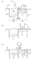
- the squeegeeing blade 23 is moved to form a powder layer 22 of a predetermined thickness on the shaping plate 21 (see FIG. 10A).
- a predetermined portion of the powder layer 22 is irradiated with the light beam L to form a solidified layer 24 from the powder layer 22 (see FIG. 10B).
- a new powder layer 22 is formed on the obtained solidified layer 24, and the light beam is irradiated again to form a new solidified layer 24.
- the solidified layer 24 is laminated (see FIG. 10C), and finally, the three-dimensional structure of the laminated solidified layer 24 is obtained.
- a shaped object can be obtained. Since the solidified layer 24 formed as the lowermost layer is in a state of being bonded to the shaping plate 21, the three-dimensional shaped article and the shaping plate 21 form an integral body, and the integral body can be used as a mold.
- the irradiated portion of the powder layer to which the light beam is irradiated becomes the solidified layer 24 through the sintering phenomenon or the solidification phenomenon.
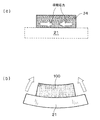
- shrinkage stress as shown in FIG. 11A may occur due to the reduction of voids between powder materials and the like.
- warpage deformation easily occurs in the integrated product of the three-dimensional shaped object 100 and the forming plate 21 of the base thereof (see FIG. 11B). That is, there is a possibility that a desired shape can not be obtained for the three-dimensional shaped object 100.
- an object of the present invention is to provide a method for producing a three-dimensional shaped object with reduced warpage.
- a step of irradiating a predetermined portion of the powder layer with a light beam to sinter or solidify the powder of the predetermined portion to form a solidified layer; and (ii) a new powder on the obtained solidified layer A method for producing a three-dimensional shaped article, wherein powder layer formation and solidified layer formation are alternately repeated by the step of forming a layer and irradiating the light beam to a predetermined portion of the new powder layer to form a further solidified layer
- a plate laminate having a shaped plate and a dummy solidified layer is used, Provided is a method for producing a three-dimensional shaped object, wherein a dummy solidified layer is formed on one main surface of the shaped plate, and a three-dimensional shaped object is produced on the other main surface of the shaped plate.
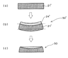
- FIG. 2 (a) preparation of a shaped plate
- FIG. 2 (b) warp deformation
- FIG. 2 (c) planar processing
- FIG. 6 (a) Preparation of a modeling plate
- FIG.6 (b) Warpage deformation
- FIG.6 (c) Planar processing
- FIG. 6 (d) Installation on support table
- Sectional drawing which showed typically the process aspect of the optical shaping composite processing in which the powder sinter lamination method is implemented
- powder layer means, for example, “metal powder layer composed of metal powder” or “resin powder layer composed of resin powder”.
- a predetermined portion of the powder layer substantially refers to a region of the three-dimensional shaped object to be manufactured. Therefore, by irradiating a light beam to the powder present at such a predetermined location, the powder is sintered or solidified to form a three-dimensional shaped object.
- solidified layer means “sintered layer” when the powder layer is a metal powder layer, and means “hardened layer” when the powder layer is a resin powder layer.
- the “upper and lower” directions described directly or indirectly in this specification are based on, for example, the positional relationship between the plate laminate and the three-dimensional shaped object at the time of manufacturing the three-dimensional shaped object,
- the side on which the three-dimensional shaped object is manufactured with respect to the plate laminate is referred to as "upward”, and the opposite side is referred to as "downward”.
- FIG. 10 schematically shows a process aspect of the optical shaping composite processing
- FIGS. 12 and 13 are flowcharts of the main configuration and operation of the optical shaping composite processing machine capable of performing the powder sinter lamination method and the cutting process. Respectively.
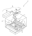
- the optical shaping combined processing machine 1 is provided with a powder layer forming means 2, a light beam irradiating means 3 and a cutting means 4 as shown in FIG.
- the powder layer forming means 2 is a means for forming a powder layer by laying a powder such as a metal powder or a resin powder with a predetermined thickness.
- the light beam irradiation means 3 is a means for irradiating the light beam L to a predetermined portion of the powder layer.
- the cutting means 4 is a means for shaving the side surface of the laminated solidified layer, that is, the surface of the three-dimensional shaped object.
- the powder layer forming means 2 mainly comprises a powder table 25, a squeezing blade 23, a support table 20 and a shaping plate 21 as shown in FIG.
- the powder table 25 is a table which can move up and down in the powder material tank 28 whose outer periphery is surrounded by the wall 26.
- the squeegee blade 23 is a blade that can be moved horizontally to provide powder 19 on powder table 25 onto support table 20 to obtain powder layer 22.
- the support table 20 is a table that can move up and down in the modeling tank 29 whose outer periphery is surrounded by the wall 27.
- the modeling plate 21 is a plate which is distribute
- the light beam irradiating means 3 mainly comprises a light beam oscillator 30 and a galvano mirror 31 as shown in FIG.
- the light beam oscillator 30 is a device that emits a light beam L.
- the galvano mirror 31 is a means for scanning the emitted light beam L onto the powder layer 22, that is, a means for scanning the light beam L.
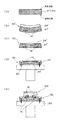
- the cutting means 4 mainly comprises an end mill 40 and a drive mechanism 41, as shown in FIG.
- the end mill 40 is a cutting tool for shaving the side of the laminated solidified layer, that is, the surface of the three-dimensional shaped object.
- the drive mechanism 41 is a means for moving the end mill 40 to a desired cutting position.
- the operation of the optical forming combined processing machine 1 is composed of a powder layer forming step (S1), a solidified layer forming step (S2) and a cutting step (S3) as shown in the flowchart of FIG.
- the powder layer forming step (S1) is a step for forming the powder layer 22.
- the support table 20 is lowered by ⁇ t (S11) so that the level difference between the upper surface of the shaping plate 21 and the upper end surface of the shaping tank 29 becomes ⁇ t.
- the squeezing blade 23 is moved horizontally from the powder material tank 28 toward the shaping tank 29, as shown in FIG.
- the powder 19 disposed on the powder table 25 can be transferred onto the shaping plate 21 (S12), and the formation of the powder layer 22 is performed (S13).
- powder materials for forming the powder layer 22 include “metal powder with an average particle diameter of about 5 ⁇ m to 100 ⁇ m” and “resin powder such as nylon, polypropylene or ABS with an average particle diameter of about 30 ⁇ m to 100 ⁇ m”. it can.
- the process proceeds to the solidified layer forming step (S2).
- the solidified layer forming step (S2) is a step of forming the solidified layer 24 by light beam irradiation.
- the light beam L is emitted from the light beam oscillator 30 (S21), and the light beam L is scanned to a predetermined place on the powder layer 22 by the galvano mirror 31 (S22). Thereby, the powder of the predetermined part of the powder layer 22 is sintered or melted and solidified to form a solidified layer 24 as shown in FIG. 10B (S23).
- a carbon dioxide gas laser, an Nd: YAG laser, a fiber laser or ultraviolet light may be used as the light beam L.
- the powder layer forming step (S1) and the solidified layer forming step (S2) are alternately repeated. Thereby, as shown in FIG. 10C, a plurality of solidified layers 24 are laminated.
- the cutting step (S3) is a step for scraping the side surface of the solidified layer 24, ie, the surface of the three-dimensional shaped object.
- the cutting step is started by driving the end mill 40 (see FIGS. 10 (c) and 12) (S31). For example, when the end mill 40 has an effective blade length of 3 mm, a cutting process of 3 mm can be performed along the height direction of the three-dimensional shaped object, so if ⁇ t is 0.05 mm, 60 layers When the solidified layer 24 is laminated, the end mill 40 is driven.
- the side surface of the laminated solidified layer 24 is cut (S32).
- S3 it is determined whether a desired three-dimensional shaped object is obtained (S33). If the desired three-dimensional shaped object is not yet obtained, the process returns to the powder layer forming step (S1). Thereafter, the powder layer forming step (S1) to the cutting step (S3) are repeatedly performed to carry out the lamination of the solidified layer and the cutting process to finally obtain a desired three-dimensional shaped object.
- the present invention is characterized in the base of the three-dimensional shaped object manufactured by the powder sinter lamination method described above.
- a plate laminate 50 composed of at least two layers is used as a base of a three-dimensional shaped object (see FIG. 1).
- the plate stack 50 it is possible to finally obtain a three-dimensional shaped object with reduced warpage.
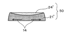
- the plate stack 50 comprises a shaped plate 21 'and a dummy solidified layer 24', as shown in FIG.
- the term "plate laminate” in the present specification means a base for producing a three-dimensional shaped object, and in particular means a plate-like base having a laminate structure.
- the laminated structure of the plate laminate 50 has a form in which the shaped plate 21 'and the dummy solidified layer 24' are laminated to each other.
- the shaped plate 21 ′ corresponds to the shaped plate 21 (see FIG. 10 (a)) that is conventionally used in the powder sinter stacking method, and in particular, has residual stress inside before the manufacture of the three-dimensional shaped shaped article. A possible plate ("residual stress" will be described later).
- the dummy solidified layer 24 ′ is a solidified layer provided on the main surface of the shaping plate 21 ′, and in particular, is provided on the main surface opposite to the main surface in contact with the three-dimensional shaped object (solidified layer 24). It is a solidified layer (see FIG. 1).
- the dummy solidified layer 24 ′ corresponds to a layer separated from the three-dimensional shaped object via the shaping plate 21 ′.
- the term “dummy” of “dummy solidified layer” used in the present specification means “different” solidified layer from the solidified layer constituting the three-dimensional shaped object manufactured on the base. Substantially means that.
- the plate laminate 50 is a laminate which has undergone warping once. That is, the precursor of the base (plate laminated body 50) of the three-dimensional shaped object used at the time of manufacture is made to generate "intentionally" warp deformation.
- the dummy solidified layer 24 ' is formed on the shaping plate 21' to obtain a laminate 50 '(see FIGS. 2A and 2B).
- the warped laminate 50 ' is preferably subjected to a planarizing process (see FIGS. 2 (b) and 2 (c)).
- a planarizing process is a process for making the main surface of the warped laminate 50 'substantially flat.
- the plate laminate 50 suitable for use in the present invention can be obtained by performing the "warpage deformation" and the "planar processing" as described above.
- both opposing main surfaces of the warped laminate 50 ′ are cut so that the plate laminate 50 has a more suitable shape as a “base” for the production of a three-dimensional shaped object. It is preferable to attach. More specifically, as shown in FIG. 2 (b) and FIG. 2 (c), the laminate 50 'is obtained so that a flat surface can be obtained on both main surfaces by removing the curved portion caused by the warpage deformation. It is preferable to carry out a cutting process. As a result, both main surfaces of the plate stack 50 have a substantially parallel relationship with each other, and when the plate stack 50 is used as the “base”, three-dimensional on a substantially horizontal plane Shaped objects can be suitably produced.
- the plate laminate 50 Since the plate laminate 50 has undergone warping once, stress remains in the interior. That is, the plate stack 50 may have residual stress in its interior. In particular, in the shaped plate 21 'constituting the plate stack 50, as shown in FIG. 3, the outwardly directed stress 14 may remain. Therefore, the warpage deformation of the three-dimensional shaped object can be reduced by utilizing the residual stress of the plate laminate 50 so as to resist the stress that may occur in the three-dimensional shaped object when manufacturing the three-dimensional shaped object. .
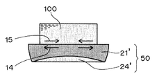
- the plate laminate 50 is installed such that “the direction of the residual stress 14 of the plate laminate 50” and “the direction of the stress 15 that may be generated in the three-dimensional shaped object 100” are opposite to each other. It is preferable to do. This is because, in the manufacture of the three-dimensional shaped object 100, these stresses (14, 15) interact so as to offset each other. That is, if the plate laminate 50 is provided as shown in FIG. 4, the stress 15 which may be generated in the three-dimensional shaped object 100 is alleviated by the residual stress 14 of the plate laminate 50, and as a result, the warp deformation is caused. Can be suitably obtained.
- the plate stack 50 In order to make “the direction of the residual stress 14 of the plate stack 50” and “the direction of the stress 15 that can be generated in the three-dimensional shaped object 100” be opposite to each other, of the two main surfaces of the plate stack 50 It is preferable to install the plate stack 50 so that the main surface on the side where the dummy solidified layer 24 ′ is not formed is on the upper side. That is, assuming that the main surface of the shaping plate 21 'on which the dummy solidified layer 24' is formed is regarded as the "front side main surface", the plate laminate 50 is installed such that the "back side main surface" of the shaping plate 21 'is on the upper side. It is preferable to do.
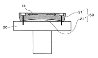
- the plate stack 50 is mounted on the support table 20 as shown in FIG. It is preferable to install in such a case, the upper exposed surface of the plate stack 50 placed on the support table 20 corresponds to the above-mentioned "back side main surface". That is, when performing the powder layer formation and the solidified layer formation using the plate laminate 50 immobilized on the support table 20, the plate is positioned so that the dummy solidified layer 24 ′ is positioned between the shaping plate 21 ′ and the support table 20. It is preferable to fix the stacked body 50 on the support table 20.
- the direction of the residual stress 14 is “outside”, and a three-dimensional shaped object manufactured on the plate laminate 50 is used.
- the possible stress direction is "inside”. Therefore, as a result, those stresses become mutually offset, and it is possible to obtain a three-dimensional shaped object with reduced warpage.
- a forming plate 21 ' is prepared.
- the shaped plate 21 ′ prepared here may be the shaped plate 21 (see FIG. 10A) that is conventionally used in the powder sinter lamination method.
- the material of the shaped plate 21 ′ is steel, cemented carbide, high-speed tool steel, alloy It may be at least one material selected from the group consisting of tool steel, stainless steel and carbon steel for machine construction.
- the shaping plate 21 ' is typically flat as a whole because it is a "plate".
- the specific shape of the shaping plate 21 ' may be any shape as long as it provides a "base" to the three-dimensional shaped object to be manufactured. Therefore, the shape of the shaping plate 21 ′ is not particularly limited to the rectangular parallelepiped shape, and may be a disk shape, a polygonal prism shape, or the like.
- the major surface size of the shaping plate 21 ' is generally required to be larger than the bottom size of the three-dimensional shaped object, and may be, for example, about 110 to 200% of the bottom size of the three-dimensional shaped object.
- the thickness of the shaping plate 21 ′ ie, the dimension of the shaping plate in the stacking direction at the time of manufacturing the three-dimensional shaped article
- the prepared shaping plate 21 ′ is subjected to warpage deformation through the formation of the dummy solidified layer 24 ′ (see FIGS. 6A and 6B). Specifically, first, a powder layer is formed on the shaping plate 21 ′, and the powder layer is irradiated with a light beam to form the dummy solidified layer 24 ′.
- the powder material used to form the dummy solidified layer 24 ' may be the same as the powder material used to manufacture the three-dimensional shaped object later. That is, for example, metal powder having an average particle diameter of about 5 ⁇ m to about 100 ⁇ m may be used. By using such powder material, a powder layer for the dummy solidified layer 24 'is formed. The powder layer is totally irradiated with a light beam, and the powder material is sintered or solidified to form the dummy solidified layer 24 '.
- the thickness of the dummy solidified layer 24 ' may be, for example, about 0.1 mm to 10 mm. As shown in FIG. 6 (b), the dummy solidified layer 24 'may be widely formed so as to extend over the entire main surface of the shaping plate 21'.
- shrinkage stress is generated due to the reduction of the voids between the powder materials, and the dummy solidified layer 24 ′ and the shaping plate 21 ′ to which it is joined are warped and deformed. Do. That is, warp deformation occurs in the stacked body 50 'including the dummy solidified layer 24' and the shaping plate 21 '. In the laminate 50 ', the stress 14 acting outward at the shaping plate 21' may remain due to the "warpage" (see FIG. 6 (b)).
- planarization processing The warped laminate 50 ′ is subjected to planarizing processing (see FIGS. 6 (b) and 6 (c)). More specifically, the laminate 50 'is subjected to a cutting process so as to obtain a flat surface by removing a curved portion resulting from the warpage deformation. As shown in the drawing, it is particularly preferable to subject both opposing main surfaces of the laminate 50 ′ to a cutting process. Thereby, both the said main surfaces become mutually parallel substantially, and the plate laminated body 50 more suitable as a base of a three-dimensional-shaped molded article will be obtained.
- Cutting means may be used to perform such planar processing.
- the cutting means may be any means capable of surface cutting, and may be, for example, a general-purpose numerical control (NC) machine tool or the like.
- a machining center (MC) capable of automatically replacing a cutting tool (end mill) is preferable.
- the end mill for example, a two-blade ball end mill made of cemented carbide is mainly used. If necessary, a square end mill, a radius end mill or the like may be used.
- surface grinding may be additionally performed using a surface grinder etc. in order to raise the flatness of both the main surfaces of laminated body 50 '.
- the plate laminate 50 obtained through the above (1) to (3) is subjected to "inversion". That is, the plate laminated body 50 obtained by performing the planarizing process after the warpage deformation is turned upside down (see FIGS. 6C and 6D). More specifically, the dummy solidified layer 24 'is positioned on the upper side relatively, and the plate stack 50 on which the shaping plate 21' is positioned on the lower side is turned upside down. Assuming that the main surface of the formed plate 21 ′ on which the dummy solidified layer 24 ′ is formed is the “front side main surface”, the plate laminate 50 is inverted so that the “back side main surface” of the formed plate 21 ′ is on the upper side. become.
- the plate stack 50 is fixed to the support table 20 so that the dummy solidified layer 24 'is positioned between the shaping plate 21' and the support table 20 by "upside down". It is preferable to do.
- the direction of the residual stress 14 of the plate stack 50 fixed on the support table 20 becomes “outside”, while the direction of the stress 15 that may be generated in the three-dimensional shaped object 100 manufactured on the plate stack 50 Is "inside” (see FIG. 6 (e)). Therefore, when the three-dimensional shaped object 100 is manufactured, the residual stress 14 of the plate laminate 50 can be suitably applied so as to cancel the “inside” stress 15.
- the three-dimensional shaped article 100 is produced using the plate laminate 50 as a base. As can be seen from the embodiment shown in FIGS. 6 (c) and 6 (e), the three-dimensional shaped object 100 will be manufactured on the "back side main surface" of the shaped plate 21 'in the plate stack 50.
- the direction of the stress 15 that can occur in the three-dimensional shaped object 100 manufactured on the plate stack 50 is "inside".
- the direction of the residual stress 14 is "outside” due to the "warpage deformation”. That is, the stress 15 at the time of manufacturing the three-dimensional shaped object 100 and the residual stress 14 of the plate laminate 50 are in opposite directions to each other. Thereby, the stress 15 at the time of manufacture of the three-dimensional shaped object 100 is relieved by the residual stress 14 of the plate laminate 50, and the warpage of the three-dimensional shaped object 100 is reduced.
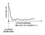
- the inventors of the present invention have found that the stress 15 generated at the time of manufacturing the three-dimensional shaped object 100 is relatively large particularly at the initial stage of manufacture (see FIG. 7). More specifically, as can be seen from FIG. 7, a large stress may occur on the bottom of the three-dimensional shaped object 100. This means that a particularly large stress occurs in the vicinity of the interface between the three-dimensional shaped object 100 and its base.
- the plate laminate 50 is used as a base, it is possible to effectively affect the stress generated in the three-dimensional shaped object 100 in the early stage of manufacture. More specifically, although the stress generated in the three-dimensional shaped object can be generated particularly large on the bottom surface of the three-dimensional shaped object, the plate laminate 50 is provided on the bottom surface. The residual stress 14 of 50 can effectively reduce the stress 15 of the three-dimensional shaped object (see FIG. 4).
- the manufacturing method of the present invention utilizes the residual stress of the plate stack to withstand the stresses that can occur in three-dimensional shaped objects. However, depending on the plate laminate, the residual stress may be smaller than the stress that may occur in the three-dimensional shaped object.
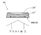
- the plate laminate is preferably subjected to blasting. Specifically, it is preferable to additionally carry out blasting on the "back side main surface" of the shaped plate 21 'of the plate laminate 50 obtained after planarizing treatment (see Fig. 8).
- Blasting can serve to strengthen the outwardly directed stress 14 in the plate stack 50. That is, in the plate laminate 50, the stress 14 that will resist the stress of the three-dimensional shaped object increases. This means that the residual stress 14 of the plate laminate 50 can be appropriately adjusted by blasting, and therefore, warpage of the three-dimensional shaped object can be reduced more efficiently.
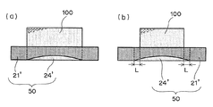
- the dummy solidified layer may be formed only on a part of the main surface of the shaping plate.
- the dummy solidified layer 24 ' is formed so that the contour shape of the dummy solidified layer 24' is substantially the same as the contour shape of the bottom of the three-dimensional shaped object 100 to be manufactured later. Do.
- the contour shape of the bottom surface of the three-dimensional shaped object 100 to be manufactured later will be the contour shape of the dummy solidified layer 24 '. (See FIG. 9 (b)). This is because if the size of the dummy solidified layer 24 ′ is increased, the residual stress 14 of the plate stack 50 can be increased by that amount.
- the dummy solidified layer 24 ' is formed so that the contour shape of the dummy solidified layer 24' is about 0.5 to 10 mm larger than the contour shape of the bottom of the three-dimensionally shaped object 100 to be manufactured later, which is merely an example. You may More specifically, the dummy solidified layer 24 'may be formed in the plate laminate 50 so as to have an equivalent dimension of about 0.5 to 10 mm as "L" shown in FIG. 9B.
- First aspect (I) a step of irradiating a predetermined portion of the powder layer with a light beam to sinter or solidify the powder of the predetermined portion to form a solidified layer; and (ii) a new powder on the obtained solidified layer
- a method for producing a three-dimensional shaped object wherein powder layer formation and solidified layer formation are alternately repeated by the step of forming a layer and irradiating the light beam to a predetermined portion of the new powder layer to form a further solidified layer
- a plate laminate having a shaped plate and a dummy solidified layer is used, In the plate laminate, while the dummy solidified layer is formed on one main surface of the shaped plate, the three-dimensional shaped object is manufactured on the other main surface of the shaped plate.
- Second aspect In the said 1st aspect, the manufacturing method of the three-dimensional-shaped molded article which performs the planar process process to the curvature-deformed laminated body obtained by formation of the said dummy solidification layer, and obtains the said plate laminated body.
- Third aspect In the said 2nd aspect, the manufacturing method of the three-dimensional-shaped molded article which attaches
- Fourth aspect In the said 2nd aspect or 3rd aspect, the manufacturing method of the three-dimensional-shaped molded article which blasts with respect to the said plate laminated body.
- the powder layer formation and the solidified layer formation are performed using the plate laminate immobilized on a support table, The manufacturing method of the three-dimensional-shaped molded article which immobilizes the said plate laminated body on this support table so that the said dummy solidification layer may be positioned between the said modeling plate and the said support table.
- the three-dimensional shaped object to be obtained is a plastic injection molding die, a press die, a die casting die, It can be used as a mold such as a casting mold and a forging mold.
- the powder layer is an organic resin powder layer and the solidified layer is a hardened layer
- the three-dimensional shaped object obtained can be used as a resin molded product.
Landscapes
- Engineering & Computer Science (AREA)
- Chemical & Material Sciences (AREA)
- Materials Engineering (AREA)
- Manufacturing & Machinery (AREA)
- Physics & Mathematics (AREA)
- Optics & Photonics (AREA)
- Mechanical Engineering (AREA)
- Plasma & Fusion (AREA)
- Powder Metallurgy (AREA)
Priority Applications (4)
| Application Number | Priority Date | Filing Date | Title |
|---|---|---|---|
| KR1020187025409A KR102145781B1 (ko) | 2016-03-09 | 2017-03-08 | 3차원 형상 조형물의 제조 방법 |
| CN201780015568.2A CN108778575A (zh) | 2016-03-09 | 2017-03-08 | 三维形状造型物的制造方法 |
| US16/083,362 US10821663B2 (en) | 2016-03-09 | 2017-03-08 | Method for manufacturing three-dimensional shaped object |
| EP17763305.4A EP3427870B1 (en) | 2016-03-09 | 2017-03-08 | Three-dimensional molded object production method |
Applications Claiming Priority (2)
| Application Number | Priority Date | Filing Date | Title |
|---|---|---|---|
| JP2016045893A JP6643631B2 (ja) | 2016-03-09 | 2016-03-09 | 三次元形状造形物の製造方法 |
| JP2016-045893 | 2016-03-09 |
Publications (1)
| Publication Number | Publication Date |
|---|---|
| WO2017154965A1 true WO2017154965A1 (ja) | 2017-09-14 |
Family
ID=59789556
Family Applications (1)
| Application Number | Title | Priority Date | Filing Date |
|---|---|---|---|
| PCT/JP2017/009190 WO2017154965A1 (ja) | 2016-03-09 | 2017-03-08 | 三次元形状造形物の製造方法 |
Country Status (6)
Cited By (1)
| Publication number | Priority date | Publication date | Assignee | Title |
|---|---|---|---|---|
| DE102019107494B4 (de) | 2018-04-06 | 2023-06-15 | Sodick Co., Ltd. | Verfahren zur Herstellung eines dreidimensionalen geformten Objekts |
Families Citing this family (7)
| Publication number | Priority date | Publication date | Assignee | Title |
|---|---|---|---|---|
| JP7087430B2 (ja) * | 2018-02-14 | 2022-06-21 | セイコーエプソン株式会社 | 三次元造形物の製造方法および三次元造形装置 |
| US10780498B2 (en) * | 2018-08-22 | 2020-09-22 | General Electric Company | Porous tools and methods of making the same |
| GB2582567A (en) * | 2019-03-25 | 2020-09-30 | Airbus Operations Ltd | Fixture for additive manufacturing and heat treatment |
| JP2022541108A (ja) * | 2019-06-29 | 2022-09-22 | 浙江大学 | 複雑曲面の空心構成の3dプリント方法 |
| JP7008669B2 (ja) * | 2019-09-09 | 2022-01-25 | 日本電子株式会社 | 3次元積層造形装置及び3次元積層造形方法 |
| US12264624B2 (en) * | 2022-06-10 | 2025-04-01 | Rtx Corporation | Build plate integrated into additive manufactured component |
| CN115213427A (zh) * | 2022-07-19 | 2022-10-21 | 季华实验室 | 增材制造的方法及产品 |
Citations (4)
| Publication number | Priority date | Publication date | Assignee | Title |
|---|---|---|---|---|
| WO2011102382A1 (ja) * | 2010-02-17 | 2011-08-25 | パナソニック電工株式会社 | 三次元形状造形物の製造方法および三次元形状造形物 |
| JP2012506803A (ja) * | 2008-10-30 | 2012-03-22 | エムティーティー テクノロジーズ リミテッド | 付加製造装置および方法 |
| JP2012224906A (ja) * | 2011-04-19 | 2012-11-15 | Panasonic Corp | 三次元形状造形物の製造方法 |
| WO2016017155A1 (ja) * | 2014-07-30 | 2016-02-04 | パナソニックIpマネジメント株式会社 | 三次元形状造形物の製造方法および三次元形状造形物 |
Family Cites Families (7)
| Publication number | Priority date | Publication date | Assignee | Title |
|---|---|---|---|---|
| US4863538A (en) | 1986-10-17 | 1989-09-05 | Board Of Regents, The University Of Texas System | Method and apparatus for producing parts by selective sintering |
| EP0542729B1 (en) | 1986-10-17 | 1996-05-22 | Board Of Regents, The University Of Texas System | Method and apparatus for producing parts by selective sintering |
| DE112008000027B4 (de) * | 2007-05-30 | 2015-05-21 | Panasonic Intellectual Property Management Co., Ltd. | Laminier-Formgebungsvorrichtung |
| JP5061062B2 (ja) * | 2008-08-08 | 2012-10-31 | パナソニック株式会社 | 三次元形状造形物の製造方法 |
| JP5895172B2 (ja) * | 2012-02-09 | 2016-03-30 | パナソニックIpマネジメント株式会社 | 三次元形状造形物の製造方法 |
| GB2500412A (en) * | 2012-03-21 | 2013-09-25 | Eads Uk Ltd | Build Plate for an additive manufacturing process |
| GB201806369D0 (en) * | 2018-04-19 | 2018-06-06 | Rolls Royce Plc | Stress relieve for additive layer manufacturing |
-
2016
- 2016-03-09 JP JP2016045893A patent/JP6643631B2/ja active Active
-
2017
- 2017-03-08 EP EP17763305.4A patent/EP3427870B1/en active Active
- 2017-03-08 US US16/083,362 patent/US10821663B2/en not_active Expired - Fee Related
- 2017-03-08 CN CN201780015568.2A patent/CN108778575A/zh active Pending
- 2017-03-08 WO PCT/JP2017/009190 patent/WO2017154965A1/ja active Application Filing
- 2017-03-08 KR KR1020187025409A patent/KR102145781B1/ko not_active Expired - Fee Related
Patent Citations (4)
| Publication number | Priority date | Publication date | Assignee | Title |
|---|---|---|---|---|
| JP2012506803A (ja) * | 2008-10-30 | 2012-03-22 | エムティーティー テクノロジーズ リミテッド | 付加製造装置および方法 |
| WO2011102382A1 (ja) * | 2010-02-17 | 2011-08-25 | パナソニック電工株式会社 | 三次元形状造形物の製造方法および三次元形状造形物 |
| JP2012224906A (ja) * | 2011-04-19 | 2012-11-15 | Panasonic Corp | 三次元形状造形物の製造方法 |
| WO2016017155A1 (ja) * | 2014-07-30 | 2016-02-04 | パナソニックIpマネジメント株式会社 | 三次元形状造形物の製造方法および三次元形状造形物 |
Non-Patent Citations (1)
| Title |
|---|
| See also references of EP3427870A4 * |
Cited By (1)
| Publication number | Priority date | Publication date | Assignee | Title |
|---|---|---|---|---|
| DE102019107494B4 (de) | 2018-04-06 | 2023-06-15 | Sodick Co., Ltd. | Verfahren zur Herstellung eines dreidimensionalen geformten Objekts |
Also Published As
| Publication number | Publication date |
|---|---|
| US20190091923A1 (en) | 2019-03-28 |
| KR20180111912A (ko) | 2018-10-11 |
| JP2017160485A (ja) | 2017-09-14 |
| CN108778575A (zh) | 2018-11-09 |
| JP6643631B2 (ja) | 2020-02-12 |
| EP3427870A1 (en) | 2019-01-16 |
| EP3427870A4 (en) | 2019-01-16 |
| EP3427870B1 (en) | 2020-01-01 |
| US10821663B2 (en) | 2020-11-03 |
| KR102145781B1 (ko) | 2020-08-19 |
Similar Documents
| Publication | Publication Date | Title |
|---|---|---|
| WO2017154965A1 (ja) | 三次元形状造形物の製造方法 | |
| CN106061717B (zh) | 三维形状造型物的制造方法 | |
| JP5519766B2 (ja) | 三次元形状造形物の製造方法および三次元形状造形物 | |
| JP5539347B2 (ja) | 三次元形状造形物の製造方法およびそれから得られる三次元形状造形物 | |
| CN103442830B (zh) | 三维形状造型物的制造方法以及三维形状造型物 | |
| TWI596001B (zh) | 三維形狀造形物之製造方法 | |
| CN104159724B (zh) | 三维形状造型物的制造方法 | |
| JP6621072B2 (ja) | 三次元形状造形物の製造方法 | |
| KR102099574B1 (ko) | 3차원 형상 조형물의 제조 방법 및 3차원 형상 조형물 | |
| CN107848212B (zh) | 三维形状造型物的制造方法 | |
| WO2012160811A1 (ja) | 三次元形状造形物の製造方法 | |
| CN108602261A (zh) | 三维形状造型物的制造方法 | |
| JP6643643B2 (ja) | 三次元形状造形物の製造方法 | |
| WO2018003798A1 (ja) | 三次元形状造形物の製造方法 | |
| JP6726858B2 (ja) | 三次元形状造形物の製造方法 | |
| JP6643644B2 (ja) | 三次元形状造形物の製造方法 |
Legal Events
| Date | Code | Title | Description |
|---|---|---|---|
| ENP | Entry into the national phase |
Ref document number: 20187025409 Country of ref document: KR Kind code of ref document: A |
|
| WWE | Wipo information: entry into national phase |
Ref document number: 1020187025409 Country of ref document: KR |
|
| NENP | Non-entry into the national phase |
Ref country code: DE |
|
| WWE | Wipo information: entry into national phase |
Ref document number: 2017763305 Country of ref document: EP |
|
| ENP | Entry into the national phase |
Ref document number: 2017763305 Country of ref document: EP Effective date: 20181009 |
|
| 121 | Ep: the epo has been informed by wipo that ep was designated in this application |
Ref document number: 17763305 Country of ref document: EP Kind code of ref document: A1 |