EP3427870A1 - Three-dimensional molded object production method - Google Patents
Three-dimensional molded object production method Download PDFInfo
- Publication number
- EP3427870A1 EP3427870A1 EP17763305.4A EP17763305A EP3427870A1 EP 3427870 A1 EP3427870 A1 EP 3427870A1 EP 17763305 A EP17763305 A EP 17763305A EP 3427870 A1 EP3427870 A1 EP 3427870A1
- Authority
- EP
- European Patent Office
- Prior art keywords
- laminate body
- shaped object
- layer
- powder
- dimensional shaped
- Prior art date
- Legal status (The legal status is an assumption and is not a legal conclusion. Google has not performed a legal analysis and makes no representation as to the accuracy of the status listed.)
- Granted
Links
- 238000004519 manufacturing process Methods 0.000 title claims abstract description 40
- 238000000034 method Methods 0.000 claims abstract description 54
- 239000000843 powder Substances 0.000 claims description 99
- 238000003754 machining Methods 0.000 claims description 39
- 230000001678 irradiating effect Effects 0.000 claims description 7
- 230000008018 melting Effects 0.000 claims description 7
- 238000002844 melting Methods 0.000 claims description 7
- 238000005245 sintering Methods 0.000 claims description 7
- 238000007711 solidification Methods 0.000 claims description 7
- 230000008023 solidification Effects 0.000 claims description 7
- 239000000463 material Substances 0.000 description 19
- 239000002184 metal Substances 0.000 description 14
- 229910052751 metal Inorganic materials 0.000 description 14
- 238000000110 selective laser sintering Methods 0.000 description 12
- 238000003801 milling Methods 0.000 description 11
- 238000000149 argon plasma sintering Methods 0.000 description 10
- 239000011347 resin Substances 0.000 description 8
- 229920005989 resin Polymers 0.000 description 8
- 230000015572 biosynthetic process Effects 0.000 description 7
- 230000000694 effects Effects 0.000 description 6
- 239000002245 particle Substances 0.000 description 5
- 238000010276 construction Methods 0.000 description 3
- CURLTUGMZLYLDI-UHFFFAOYSA-N Carbon dioxide Chemical compound O=C=O CURLTUGMZLYLDI-UHFFFAOYSA-N 0.000 description 2
- XEEYBQQBJWHFJM-UHFFFAOYSA-N Iron Chemical compound [Fe] XEEYBQQBJWHFJM-UHFFFAOYSA-N 0.000 description 2
- 229910001315 Tool steel Inorganic materials 0.000 description 2
- 230000003028 elevating effect Effects 0.000 description 2
- 238000000227 grinding Methods 0.000 description 2
- 230000010354 integration Effects 0.000 description 2
- 238000009877 rendering Methods 0.000 description 2
- 238000003860 storage Methods 0.000 description 2
- 230000003746 surface roughness Effects 0.000 description 2
- 239000011800 void material Substances 0.000 description 2
- 229910000975 Carbon steel Inorganic materials 0.000 description 1
- 239000004677 Nylon Substances 0.000 description 1
- 239000004743 Polypropylene Substances 0.000 description 1
- 229910000831 Steel Inorganic materials 0.000 description 1
- 229920000122 acrylonitrile butadiene styrene Polymers 0.000 description 1
- 239000004676 acrylonitrile butadiene styrene Substances 0.000 description 1
- 229910045601 alloy Inorganic materials 0.000 description 1
- 239000000956 alloy Substances 0.000 description 1
- 229910002092 carbon dioxide Inorganic materials 0.000 description 1
- 239000001569 carbon dioxide Substances 0.000 description 1
- 239000010962 carbon steel Substances 0.000 description 1
- 238000005266 casting Methods 0.000 description 1
- 238000005520 cutting process Methods 0.000 description 1
- 238000004512 die casting Methods 0.000 description 1
- 238000005516 engineering process Methods 0.000 description 1
- 239000000835 fiber Substances 0.000 description 1
- 238000005242 forging Methods 0.000 description 1
- 238000001746 injection moulding Methods 0.000 description 1
- 229910052742 iron Inorganic materials 0.000 description 1
- 238000003475 lamination Methods 0.000 description 1
- 238000000465 moulding Methods 0.000 description 1
- 229920001778 nylon Polymers 0.000 description 1
- 239000004033 plastic Substances 0.000 description 1
- -1 polypropylene Polymers 0.000 description 1
- 229920001155 polypropylene Polymers 0.000 description 1
- 239000002243 precursor Substances 0.000 description 1
- 238000002360 preparation method Methods 0.000 description 1
- 239000010935 stainless steel Substances 0.000 description 1
- 229910001220 stainless steel Inorganic materials 0.000 description 1
- 239000010959 steel Substances 0.000 description 1
Images


Classifications
-
- B—PERFORMING OPERATIONS; TRANSPORTING
- B29—WORKING OF PLASTICS; WORKING OF SUBSTANCES IN A PLASTIC STATE IN GENERAL
- B29C—SHAPING OR JOINING OF PLASTICS; SHAPING OF MATERIAL IN A PLASTIC STATE, NOT OTHERWISE PROVIDED FOR; AFTER-TREATMENT OF THE SHAPED PRODUCTS, e.g. REPAIRING
- B29C64/00—Additive manufacturing, i.e. manufacturing of three-dimensional [3D] objects by additive deposition, additive agglomeration or additive layering, e.g. by 3D printing, stereolithography or selective laser sintering
- B29C64/20—Apparatus for additive manufacturing; Details thereof or accessories therefor
- B29C64/245—Platforms or substrates
-
- B—PERFORMING OPERATIONS; TRANSPORTING
- B22—CASTING; POWDER METALLURGY
- B22F—WORKING METALLIC POWDER; MANUFACTURE OF ARTICLES FROM METALLIC POWDER; MAKING METALLIC POWDER; APPARATUS OR DEVICES SPECIALLY ADAPTED FOR METALLIC POWDER
- B22F10/00—Additive manufacturing of workpieces or articles from metallic powder
- B22F10/10—Formation of a green body
-
- B—PERFORMING OPERATIONS; TRANSPORTING
- B22—CASTING; POWDER METALLURGY
- B22F—WORKING METALLIC POWDER; MANUFACTURE OF ARTICLES FROM METALLIC POWDER; MAKING METALLIC POWDER; APPARATUS OR DEVICES SPECIALLY ADAPTED FOR METALLIC POWDER
- B22F10/00—Additive manufacturing of workpieces or articles from metallic powder
- B22F10/20—Direct sintering or melting
- B22F10/28—Powder bed fusion, e.g. selective laser melting [SLM] or electron beam melting [EBM]
-
- B—PERFORMING OPERATIONS; TRANSPORTING
- B22—CASTING; POWDER METALLURGY
- B22F—WORKING METALLIC POWDER; MANUFACTURE OF ARTICLES FROM METALLIC POWDER; MAKING METALLIC POWDER; APPARATUS OR DEVICES SPECIALLY ADAPTED FOR METALLIC POWDER
- B22F10/00—Additive manufacturing of workpieces or articles from metallic powder
- B22F10/40—Structures for supporting workpieces or articles during manufacture and removed afterwards
-
- B—PERFORMING OPERATIONS; TRANSPORTING
- B22—CASTING; POWDER METALLURGY
- B22F—WORKING METALLIC POWDER; MANUFACTURE OF ARTICLES FROM METALLIC POWDER; MAKING METALLIC POWDER; APPARATUS OR DEVICES SPECIALLY ADAPTED FOR METALLIC POWDER
- B22F3/00—Manufacture of workpieces or articles from metallic powder characterised by the manner of compacting or sintering; Apparatus specially adapted therefor ; Presses and furnaces
- B22F3/12—Both compacting and sintering
- B22F3/16—Both compacting and sintering in successive or repeated steps
-
- B—PERFORMING OPERATIONS; TRANSPORTING
- B29—WORKING OF PLASTICS; WORKING OF SUBSTANCES IN A PLASTIC STATE IN GENERAL
- B29C—SHAPING OR JOINING OF PLASTICS; SHAPING OF MATERIAL IN A PLASTIC STATE, NOT OTHERWISE PROVIDED FOR; AFTER-TREATMENT OF THE SHAPED PRODUCTS, e.g. REPAIRING
- B29C64/00—Additive manufacturing, i.e. manufacturing of three-dimensional [3D] objects by additive deposition, additive agglomeration or additive layering, e.g. by 3D printing, stereolithography or selective laser sintering
- B29C64/10—Processes of additive manufacturing
- B29C64/106—Processes of additive manufacturing using only liquids or viscous materials, e.g. depositing a continuous bead of viscous material
- B29C64/124—Processes of additive manufacturing using only liquids or viscous materials, e.g. depositing a continuous bead of viscous material using layers of liquid which are selectively solidified
- B29C64/129—Processes of additive manufacturing using only liquids or viscous materials, e.g. depositing a continuous bead of viscous material using layers of liquid which are selectively solidified characterised by the energy source therefor, e.g. by global irradiation combined with a mask
- B29C64/135—Processes of additive manufacturing using only liquids or viscous materials, e.g. depositing a continuous bead of viscous material using layers of liquid which are selectively solidified characterised by the energy source therefor, e.g. by global irradiation combined with a mask the energy source being concentrated, e.g. scanning lasers or focused light sources
-
- B—PERFORMING OPERATIONS; TRANSPORTING
- B29—WORKING OF PLASTICS; WORKING OF SUBSTANCES IN A PLASTIC STATE IN GENERAL
- B29C—SHAPING OR JOINING OF PLASTICS; SHAPING OF MATERIAL IN A PLASTIC STATE, NOT OTHERWISE PROVIDED FOR; AFTER-TREATMENT OF THE SHAPED PRODUCTS, e.g. REPAIRING
- B29C64/00—Additive manufacturing, i.e. manufacturing of three-dimensional [3D] objects by additive deposition, additive agglomeration or additive layering, e.g. by 3D printing, stereolithography or selective laser sintering
- B29C64/10—Processes of additive manufacturing
- B29C64/141—Processes of additive manufacturing using only solid materials
- B29C64/153—Processes of additive manufacturing using only solid materials using layers of powder being selectively joined, e.g. by selective laser sintering or melting
-
- B—PERFORMING OPERATIONS; TRANSPORTING
- B29—WORKING OF PLASTICS; WORKING OF SUBSTANCES IN A PLASTIC STATE IN GENERAL
- B29C—SHAPING OR JOINING OF PLASTICS; SHAPING OF MATERIAL IN A PLASTIC STATE, NOT OTHERWISE PROVIDED FOR; AFTER-TREATMENT OF THE SHAPED PRODUCTS, e.g. REPAIRING
- B29C64/00—Additive manufacturing, i.e. manufacturing of three-dimensional [3D] objects by additive deposition, additive agglomeration or additive layering, e.g. by 3D printing, stereolithography or selective laser sintering
- B29C64/10—Processes of additive manufacturing
- B29C64/165—Processes of additive manufacturing using a combination of solid and fluid materials, e.g. a powder selectively bound by a liquid binder, catalyst, inhibitor or energy absorber
-
- B—PERFORMING OPERATIONS; TRANSPORTING
- B33—ADDITIVE MANUFACTURING TECHNOLOGY
- B33Y—ADDITIVE MANUFACTURING, i.e. MANUFACTURING OF THREE-DIMENSIONAL [3-D] OBJECTS BY ADDITIVE DEPOSITION, ADDITIVE AGGLOMERATION OR ADDITIVE LAYERING, e.g. BY 3-D PRINTING, STEREOLITHOGRAPHY OR SELECTIVE LASER SINTERING
- B33Y10/00—Processes of additive manufacturing
-
- B—PERFORMING OPERATIONS; TRANSPORTING
- B33—ADDITIVE MANUFACTURING TECHNOLOGY
- B33Y—ADDITIVE MANUFACTURING, i.e. MANUFACTURING OF THREE-DIMENSIONAL [3-D] OBJECTS BY ADDITIVE DEPOSITION, ADDITIVE AGGLOMERATION OR ADDITIVE LAYERING, e.g. BY 3-D PRINTING, STEREOLITHOGRAPHY OR SELECTIVE LASER SINTERING
- B33Y30/00—Apparatus for additive manufacturing; Details thereof or accessories therefor
-
- B—PERFORMING OPERATIONS; TRANSPORTING
- B33—ADDITIVE MANUFACTURING TECHNOLOGY
- B33Y—ADDITIVE MANUFACTURING, i.e. MANUFACTURING OF THREE-DIMENSIONAL [3-D] OBJECTS BY ADDITIVE DEPOSITION, ADDITIVE AGGLOMERATION OR ADDITIVE LAYERING, e.g. BY 3-D PRINTING, STEREOLITHOGRAPHY OR SELECTIVE LASER SINTERING
- B33Y40/00—Auxiliary operations or equipment, e.g. for material handling
- B33Y40/20—Post-treatment, e.g. curing, coating or polishing
-
- B—PERFORMING OPERATIONS; TRANSPORTING
- B22—CASTING; POWDER METALLURGY
- B22F—WORKING METALLIC POWDER; MANUFACTURE OF ARTICLES FROM METALLIC POWDER; MAKING METALLIC POWDER; APPARATUS OR DEVICES SPECIALLY ADAPTED FOR METALLIC POWDER
- B22F12/00—Apparatus or devices specially adapted for additive manufacturing; Auxiliary means for additive manufacturing; Combinations of additive manufacturing apparatus or devices with other processing apparatus or devices
- B22F12/30—Platforms or substrates
-
- B—PERFORMING OPERATIONS; TRANSPORTING
- B22—CASTING; POWDER METALLURGY
- B22F—WORKING METALLIC POWDER; MANUFACTURE OF ARTICLES FROM METALLIC POWDER; MAKING METALLIC POWDER; APPARATUS OR DEVICES SPECIALLY ADAPTED FOR METALLIC POWDER
- B22F12/00—Apparatus or devices specially adapted for additive manufacturing; Auxiliary means for additive manufacturing; Combinations of additive manufacturing apparatus or devices with other processing apparatus or devices
- B22F12/40—Radiation means
- B22F12/41—Radiation means characterised by the type, e.g. laser or electron beam
-
- B—PERFORMING OPERATIONS; TRANSPORTING
- B22—CASTING; POWDER METALLURGY
- B22F—WORKING METALLIC POWDER; MANUFACTURE OF ARTICLES FROM METALLIC POWDER; MAKING METALLIC POWDER; APPARATUS OR DEVICES SPECIALLY ADAPTED FOR METALLIC POWDER
- B22F12/00—Apparatus or devices specially adapted for additive manufacturing; Auxiliary means for additive manufacturing; Combinations of additive manufacturing apparatus or devices with other processing apparatus or devices
- B22F12/40—Radiation means
- B22F12/49—Scanners
-
- B—PERFORMING OPERATIONS; TRANSPORTING
- B22—CASTING; POWDER METALLURGY
- B22F—WORKING METALLIC POWDER; MANUFACTURE OF ARTICLES FROM METALLIC POWDER; MAKING METALLIC POWDER; APPARATUS OR DEVICES SPECIALLY ADAPTED FOR METALLIC POWDER
- B22F12/00—Apparatus or devices specially adapted for additive manufacturing; Auxiliary means for additive manufacturing; Combinations of additive manufacturing apparatus or devices with other processing apparatus or devices
- B22F12/60—Planarisation devices; Compression devices
- B22F12/67—Blades
-
- Y—GENERAL TAGGING OF NEW TECHNOLOGICAL DEVELOPMENTS; GENERAL TAGGING OF CROSS-SECTIONAL TECHNOLOGIES SPANNING OVER SEVERAL SECTIONS OF THE IPC; TECHNICAL SUBJECTS COVERED BY FORMER USPC CROSS-REFERENCE ART COLLECTIONS [XRACs] AND DIGESTS
- Y02—TECHNOLOGIES OR APPLICATIONS FOR MITIGATION OR ADAPTATION AGAINST CLIMATE CHANGE
- Y02P—CLIMATE CHANGE MITIGATION TECHNOLOGIES IN THE PRODUCTION OR PROCESSING OF GOODS
- Y02P10/00—Technologies related to metal processing
- Y02P10/25—Process efficiency
Definitions
- the present invention relates to a method for manufacturing a three-dimensional shaped object. More particularly, the present invention relates to a method for manufacturing a three-dimensional shaped object, in which a formation of a solidified layer is performed by an irradiation of a powder layer with a light beam.
- a method for manufacturing a three-dimensional shaped object by irradiating a powder material with a light beam has been known (such method can be generally referred to as a "selective laser sintering method") .
- the method can produce the three-dimensional shaped object by an alternate repetition of a powder-layer forming and a solidified-layer forming on the basis of the following (i) and (ii) :
- the three-dimensional shaped object can be used as a metal mold in a case where inorganic powder material (e.g., metal powder material) is used as the powder material. While on the other hand, the three-dimensional shaped object can also be used as various kinds of models or replicas in a case where organic powder material (e.g., resin powder material) is used as the powder material.
- inorganic powder material e.g., metal powder material
- organic powder material e.g., resin powder material
- a squeegee blade 23 is forced to move, and thereby a powder layer 22 with its predetermined thickness is formed on the base plate 21 (see Fig. 10A ). Then, a predetermined portion of the powder layer 22 is irradiated with a light beam "L" to form a solidified layer 24 therefrom (see Fig. 10B ).
- Another powder layer 22 is newly provided on the solidified layer 24 thus formed, and is irradiated again with the light beam to form another solidified layer 24.
- the powder-layer forming and the solidified-layer forming are alternately repeated, allowing the solidified layers 24 to be stacked with each other (see Fig. 10C ).
- Such alternate repetition of the powder-layer forming and the solidified-layer forming leads to a production of a three-dimensional shaped object with a plurality of the solidified layers 24 integrally stacked therein.
- the lowermost solidified layer 24 can be provided in a state of adhering to the surface of the base plate 21. Therefore, there can be obtained an integration of the three-dimensional shaped object and the base plate 21.
- the integrated "three-dimensional shaped object" and "base plate” can be used as the metal mold as they are.
- PATENT DOCUMENT 1 Japanese Unexamined Patent Application Publication No. H01-502890
- the irradiated portion of the powder layer with the light beam transforms into the solidified layer 24 through a sintering phenomenon or a melting and subsequent solidification phenomenon.
- a shrinkage stress can occur due to a reduced void between particles of the powder material ( Fig. 11A ).
- the integrated object of the three-dimensional shaped obj ect 100 and the base plate 21 i. e. , a platform for the object 100
- becomes susceptible to a warp deformation Fig. 11B ). This will bring concern that a desired shape of the three-dimensional shaped object 100 cannot be provided.
- an object of the present invention is to provide a manufacturing method of a three-dimensional shaped object, the method being capable of reducing a warp deformation of the three-dimensional shaped object.
- an embodiment of the present invention provides a method for manufacturing a three-dimensional shaped object by alternate repetition of a powder-layer forming and a solidified-layer forming, the repetition comprising:
- the three-dimensional shaped object can be obtained with its warp deformation being reduced.
- powder layer as used in this description and claims means a "metal powder layer made of a metal powder” or "resin powder layer made of a resin powder", for example.
- predetermined portion of a powder layer substantially means a portion of a three-dimensional shaped object to be manufactured. As such, a powder present in such predetermined portion is irradiated with a light beam, and thereby the powder undergoes a sintering or a melting and subsequent solidification to give a shape of a three-dimensional shaped object.
- solidified layer substantially means a “sintered layer” in a case where the powder layer is a metal powder layer
- solidified layer substantially means a "cured layer” in a case where the powder layer is a resin powder layer
- the directions of "upper” and “lower”, which are directly or indirectly used herein, are ones based on a positional relationship between a plate laminate body and a three-dimensional shaped object at a point in time when the three-dimensional shaped object is manufactured.
- the side in which the manufactured three-dimensional shaped object is positioned with respect to the plate laminate body is "upper”, and the opposite direction thereto is “lower”.
- a selective laser sintering method on which the manufacturing method of the present invention is based, will be described.
- a laser-sintering/machining hybrid process wherein a machining is additionally carried out in the selective laser sintering method will be especially explained.
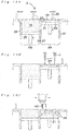
- Figs. 10A-10C schematically show a process embodiment of the laser-sintering/machining hybrid.
- Figs. 12 and 13 respectively show major constructions and operation flow regarding a laser-sintering/milling hybrid machine for enabling an execution of a machining process as well as the selective laser sintering method.
- the laser-sintering/milling hybrid machine 1 is provided with a powder layer former 2, a light-beam irradiator 3, and a machining means 4.
- the powder layer former 2 is a means for forming a powder layer with its predetermined thickness through a supply of powder (e.g., a metal powder or a resin powder).
- the light-beam irradiator 3 is a means for irradiating a predetermined portion of the powder layer with a light beam "L”.
- the machining means 4 is a means for milling the side surface of the stacked solidified layers, i.e., the surface of the three-dimensional shaped object.
- the powder layer former 2 is mainly composed of a powder table 25, a squeegee blade 23, a support table 20 and a base plate 21.
- the powder table 25 is a table capable of vertically elevating/descending in a "storage tank for powder material" 28 whose outer periphery is surrounded with a wall 26.
- the squeegee blade 23 is a blade capable of horizontally moving to spread a powder 19 from the powder table 25 onto the forming table 20, and thereby forming a powder layer 22.
- the forming table 20 is a table capable of vertically elevating/descending in a forming tank 29 whose outer periphery is surrounded with a wall 27.
- the base plate 21 is placed on the forming table 20 and serves as a platform of the three-dimensional shaped object.
- the light-beam irradiator 3 is mainly composed of a light beam generator 30 and a galvanometer mirror 31.
- the light beam generator 30 is a device for emitting a light beam "L”.
- the galvanometer mirror 31 is a means for scanning an emitted light beam "L” onto the powder layer 22, i.e., a scan means of the light beam "L”.
- the machining means 4 is mainly composed of an end mill 40 and an actuator 41.
- the end mill 40 is a cutting tool for milling the side surface of the stacked solidified layers, i.e., the surface of the three-dimensional shaped object.
- the actuator 41 is a means for driving the end mill 40 to move toward the position to be milled.
- the operations of the laser-sintering/milling hybrid machine 1 are mainly composed of a powder layer forming step (S1), a solidified layer forming step (S2), and a machining step (S3).
- the powder layer forming step (S1) is a step for forming the powder layer 22.
- the support table 20 is descended by ⁇ t (S11), and thereby creating a level difference ⁇ t between an upper surface of the base plate 21 and an upper-edge plane of the forming tank 29.
- the powder table 25 is elevated by ⁇ t, and then the squeegee blade 23 is driven to move from the storage tank 28 to the forming tank 29 in the horizontal direction, as shown in Fig. 10A .
- This enables a powder 19 placed on the powder table 25 to be spread onto the base plate 21 (S12), while forming the powder layer 22 (S13).
- the powder for the powder layer 22 include a "metal powder having a mean particle diameter of about 5 ⁇ m to 100 ⁇ m" and a "resin powder having a mean particle diameter of about 30 ⁇ m to 100 ⁇ m (e.g., a powder of nylon, polypropylene, ABS or the like".
- the solidified layer forming step (S2) is a step for forming a solidified layer 24 through the light beam irradiation.
- a light beam "L” is emitted from the light beam generator 30 (S21) .
- the emitted light beam "L” is scanned onto a predetermined portion of the powder layer 22 by the galvanometer mirror 31 (S22) .
- the scanned light beam can cause the powder in the predetermined portion of the powder layer 22 to be sintered or be melted and subsequently solidified, resulting in a formation of the solidified layer 24 (S23), as shown in Fig. 10B .
- Examples of the light beam "L” include carbon dioxide gas laser, Nd:YAG laser, fiber laser, ultraviolet light, and the like.
- the powder layer forming step (S1) and the solidified layer forming step (S2) are alternately repeated. This allows a plurality of the solidified layers 24 to be integrally stacked with each other, as shown in Fig. 10C .
- the machining step (S3) is a step for milling the side surface of the stacked solidified layers 24, i.e., the surface of the three-dimensional shaped object.
- the end mill 40 (see Fig. 10C and Fig. 12 ) is actuated to initiate an execution of the machining step (S31) .
- a machining can be performed with a milling depth of 3 mm. Therefore, supposing that " ⁇ t" is 0.05 mm, the end mill 40 is actuated when the formation of the sixty solidified layers 24 is completed.
- the side face of the stacked solidified layers 24 is subjected to the surface machining (S32) through a movement of the end mill 40 driven by the actuator 41. Subsequent to the surface machining step (S3), it is judged whether or not the whole three-dimensional shaped object has been obtained (S33). When a desired three-dimensional shaped object has not yet been obtained, the step returns to the powder layer forming step (S1). Thereafter, the steps S1 through S3 are repeatedly performed again wherein the further stacking of the solidified layer and the further machining process therefor are similarly performed, which eventually leads to a provision of the desired three-dimensional shaped object.
- the present invention is characterized by a platform for the three-dimensional shaped object to be manufactured in the selective laser sintering method.
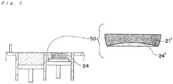
- the present invention makes use of a plate laminate body 50 composed of at least two layers as a platform for a three-dimensional shaped object (see. Fig. 1 ).
- the use of the plate laminate body 50 can lead to a production of the three-dimensional shaped object with its warp deformation being reduced.
- the plate laminate body 50 comprises a dummy solidified layer 24' and a base plate 21' for shaped object.
- the term " plate laminate body” as used herein refers to a platform for a manufacturing of a three-dimensional shaped object, and in particular such term means the platform in a form of plate having a laminar structure.
- the laminar structure of the plate laminate body 50 has such a form that the base plate 21' and the dummy solidified layer 24' are stacked with each other.
- the base plate 21' corresponds to a conventional base plate 21 (see Fig. 10A ), but the base plate 21' is a plate which can have a residual stress in the interior thereof at a point in time before the three-dimensional shaped object is manufactured ("residual stress" herein will be later described in detail) .
- the dummy solidified layer 24' which is a solidified layer provided on a principal surface of the base plate 21', is particularly a solidified layer provided on the principal surface which is opposite to a principal surface with which the three-dimensional shaped object (i.e., the solidified layer 24 thereof) comes into contact (see Fig. 1 ).
- the dummy solidified layer 24' corresponds to a layer spaced via the base plate 21' with respect to the three-dimensional shaped object to be manufactured.
- the term "dummy" of the dummy solidified layer herein substantially refers to a "different” solidified layer which differs from the solidified layers of the three-dimensional shaped object to be manufactured on a platform.
- the plate laminate body 50 is a laminate body which has been once warp-deformed. Namely, according to the present invention, a warp deformation has been proactively caused in a precursor of the platform (i.e., plate laminate body) for the three-dimensional shaped object to be manufactured.
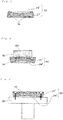
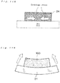
- the plate laminate body 50 is obtained by subjecting a warp-deformed laminate body 50' to a flattening process, the warp-deformed laminate body 50' being obtained by performing the forming of the dummy solidified layer 24'. See Fig. 2 .
- the plate laminate body 50 thus obtained is preferably provided prior to the manufacturing of the three-dimensional shaped object.
- the laminate body 50' is prepared by a forming of the dummy solidified layer 24' on the base plate 21' (see Figs. 2A and 2B ). Similarly to the phenomenon as described with reference to Figs. 11A and 11B , a warp deformation is caused in the laminate body 50' upon the forming of the dummy solidified layer 24'. Subsequently, the laminate body 50' thus warp-deformed is subjected to a flattening process (see Figs. 2B and 2C ). It is preferred that the flattening process is performed such that the laminate body 50' gets to be a suitable body for the "platform" in particular. The flattening process is a process for rendering a principal surface of the warp-deformed laminate body 50' flat. Through such "warp deformation” and "flattening process", the plate laminate body 50 suitable for use in the present invention can be eventually provided.
- the plate laminate body 50 In order for the plate laminate body 50 to have a more suitable form of "platform" for the manufacturing of the three-dimensional shaped object, it is preferred that opposed principal surfaces of the warp-deformed laminate body 50' are both subjected to a machining process as the flattening process. More specifically, it is preferred that the machining process is performed with respect to the laminate body 50' by removing a curved portion thereof attributed to the warp deformation, and thereby rendering the both principal surfaces of the body 50' flat. See Figs. 2B and 2C , for example. Such flattening process makes it possible for the both principal surfaces of the plate laminate body to have a substantially parallel relationship with each other. With the use of such plate laminate body 50, the three-dimensional shaped object can be suitable manufactured on the substantially horizontal plane.
- the plate laminate body 50 has a stress remaining in the interior thereof since the body has once underwent the warp deformation. That is, the plate laminate body 50 can have a residual stress in the interior thereof. In particular, an outward stress 14 can remain in the base plate 21' of the plate laminate body 50, as shown in Fig. 3 .
- the residual stress of the plate laminate body 50 is utilized upon the manufacturing of the three-dimensional shaped object so as to be against a stress which may be generated in the three-dimensional shaped object, and thereby the warp deformation of the three-dimensional shaped object can be reduced.
- the plate laminate body 50 is preferably placed such that "direction of the residual stress 14 of the plate laminate body 50" and "direction of the stress 15 generated in the three-dimensional shaped object 100" are opposite to each other.
- the reason for this is that an offset effect between these stresses (14, 15) can be brought about.
- the placing of the plate laminate body 50 as shown in Fig. 4 allows the stress 15 generated in the three-dimensional shaped object 100 to be mitigated by the residual stress 14 of the plate laminate body 50, which leads to a suitable production of the three-dimensional shaped object 100 with the warp deformation thereof being reduced.
- the plate laminate body 50 is preferably placed such that one of the principal surfaces of the plate laminate body 50, which is provided with no dummy solidified layer 24', faces upward.
- the placing of the plate laminate body 50 is preferably such that the back principal surface of the base plate 21' faces upward.
- the plate laminate body 50 is placed onto a support table 20 as shown in Fig. 5 .
- an upper exposed surface of the plate laminate body 50 placed on the support table 20 corresponds to the above "back principal surface”. It is thus preferred that, when the powder-layer forming and the solidified-layer forming are performed on the plate laminate body 50 secured to the support table 20, the securing of the plate laminate body 50 with respect to the support table 20 is such that the dummy solidified layer 24' is positioned between the base plate 21' and the support table 20.
- the residual stress 14 in the plate laminate body 50 secured to the support table 20 has a direction of "outward", whereas the stress which can be generated in the three-dimensional shaped object 100 manufactured on such plate laminate body 50 has a direction of "inward".
- an offset effect between these stresses can be brought about, which leads to a suitable production of the three-dimensional shaped object 100 while the warp deformation thereof is reduced.
- the base plate 21' for the shaped object is provided as shown in Fig. 6A .
- the base plate 21' for the shaped object may be a base plate 21 used conventionally in the selective laser sintering method (see Fig. 10A ).
- the base plate 21' is preferably made of at least one material selected from the group consisting of a steel, a hardmetal (cemented carbide), a high-speed tool steel, an alloy tool steel, a stainless steel, and a carbon steel for machine construction.
- the base plate 21' typically has a flattened form as a whole because of "plate".
- the specific form of the base plate 21' is not particularly limited as long as it serves as a platform for the three-dimensional shaped object.
- the form of the base plate 21' is not only a cuboid form, but also may be a disc form, a polygonal column form or the like.
- the principal surface of the base plate 21' is generally required to have a larger size than that of the bottom surface of the three-dimensional shaped object.
- the principal surface of the base plate 21' has the larger size in 110% to 200% of that of the bottom surface of the shaped object.
- the thickness of the base plate 21' i.e., a base plate dimension along the stacking direction in the manufacturing of the three-dimensional shaped object to be manufactured may be for example in the range of about 10 mm to about 70 mm.
- the base plate 21' itself is subjected to a warp deformation through the forming of the dummy solidified layer 24' (see Figs. 6A and 6B ). Specifically, first, a powder layer is formed on the base plate 21', and then the dummy solidified layer 24' is formed by irradiation of the powder layer with the light beam.
- the powder material to be used for the formation of the dummy solidified layer 24' may be the same as the powder material used for the subsequent manufacturing of the three-dimensional shaped object.
- the metal powder with its mean particle diameter of about 5 ⁇ m to 100 ⁇ m may be used.
- a powder layer for the dummy solidified layer 24' can be formed.
- the resulting powder layer is wholly irradiated with the light beam. This causes a sintering of the powder material or a melting and subsequent solidification of the powder material, and thereby the dummy solidified layer 24' is formed.
- the thickness of the dummy solidified layer 24' may be in the range of 0.1 mm to 10 mm, for example.
- the dummy solidified layer 24' may be widely formed such that the dummy solidified layer 24' covers the whole principal surface of the base plate 21', as shown in Fig. 6B .
- a shrinkage stress can occur due to a reduced void between particles of the powder material, and thereby causing the dummy solidified layer 24' and the base plate 21' bonded thereto to be warp-deformed.
- the laminate body 50' has an outward stress 14 that can remain in the base plate 21' due to the warp deformation (see Fig. 6B ).
- a flattening process is performed with respect to the warp-deformed laminate body 50' (see Figs. 6B and 6C ). More specifically, a machining process is performed with respect to the laminate body 50' by removing its curved portion attributed to the warp deformation, and thereby providing the flat surface of the laminate body. As can be seen from Figs. 6B and 6C , it is preferred that the opposed principal surfaces of the laminate body 50' are both subjected to the machining process. This makes it possible for the both principal surfaces of the plate laminate body 50 to be parallel with each other, which leads to a suitable provision of the plate laminate body 50 using as the platform for the three-dimensional shaped object.
- a machining means may be used.
- the machining means may be any suitable one as long as it performs a surface machining treatment.
- the machining means may be a numerical control (NC: Numerical Control) machine tool or those analogous thereto.
- NC numerical Control
- the machining means is a machining center (MC) whose milling tool (end mill) is automatically exchangeable.
- MC machining center
- end mill for example, a twin bladed ball end mill made of a superhard material is mainly used.
- a square end mill, a radius end mill or the like may also be used in some cases.
- a flat grinding process may be additionally performed by a surface grinding machine or the like.
- the plate laminate body 50 obtained through the above (1) to (3) is subjected to an inversion. That is, the plate laminate body 50, which is one obtained by the flattening process of the warp-deformed body, is flipped so that the upper and lower principal surfaces of the plate laminate body are inverted with each other (see Figs. 6C and 6D ). More specifically, the plate laminate body 50 with the dummy solidified layer 24' being positioned on the upper side, whereas the base plate 21' being positioned on the lower side is flipped such that the inversion thereof is given.
- the inversion of the plate laminate body 50 is performed such that the back principal surface of the base plate 21' gets to face upward.
- the plate laminate body 50 is secured with respect to the support table 20 such that the dummy solidified layer 24' is positioned between the base plate 21' and the support table 20.
- This allows the residual stress 14 in the plate laminate body 50 secured to the support table 20 to have a direction of "outward", whereas the stress which can be generated in the three-dimensional shaped object 100 to be manufactured on the plate laminate body 50 has a direction of "inward” (see Figs. 6E ).
- the residual stress 14 of the plate laminate body 50 can suitably act against the inward stress 15 such that the offset effect between these stresses can be given at a point in time during the three-dimensional shaped object 100 is manufactured.
- the manufacturing of the three-dimensional shaped object 100 is initiated using the secured plate laminate body 50 as the platform for the shaped object. As can be seen from Figs. 6C and 6E , the three-dimensional shaped object 100 is manufactured on the "back principal surface" of the base plate 21' of the plate laminate body 50.
- the direction of the stress 15 that can be generated in the three-dimensional shaped object 100 to be manufactured on the plate laminate body 50 is "inward". While on the other hand, the direction of the residual stress 14 in the plate laminate body 50 is "outward" due to the warp deformation of the body. That is, the stress 15 generated upon the manufacturing of the three-dimensional shaped object 100 and the residual stress 14 of the plate laminate body 50 have the opposite directions to each other. This enables the stress 15 generated upon the manufacturing of the three-dimensional shaped object 100 to be mitigated by the residual stress 14 of the plate laminate body 50, which leads to a reduction in the warp deformation of the three-dimensional shaped object 100.
- the inventors of the present application have found that the stress 15 generated during the manufacturing of the three-dimensional shaped object 100 is larger at an earlier stage of the manufacturing (see Fig. 7 ). More specifically, as can be seen from Fig. 7 , the large stress occurs especially at the bottom surface of the three-dimensional shaped object 100. This means that there is a large stress generated especially at a boundary region between the three-dimensional shaped object 100 and the platform therefor.
- the use of the plate laminate body 50 as the platform according to the manufacturing method of the present invention can effectively affect the stress generated in the three-dimensional shaped object at the earlier stage of the manufacturing thereof More specifically, although the larger stress occurs especially at the bottom surface of the three-dimensional shaped object, such bottom surface is provided with the plate laminate body 50, which can effectively reduce the stress 15 of the three-dimensional shaped object by the residual stress 14 of the plate laminate body 50 (see Fig. 4 ) .
- the manufacturing method of the present invention makes use of the residual stress of the plate laminate body to act against the stress that can be generated in the three-dimensional shaped object. It is, however, conceivable that there may be such a plate laminate body that the residual stress thereof is smaller than the stress of the three-dimensional shaped object.
- the plate laminate body is subjected to a blast machining.
- the blast machining is additionally performed with respect to the "back principal surface" of the base plate 21' of the plate laminate body 50 obtained after the flattening process (see Fig. 8 ).
- the blast machining of the plate laminate body 50 can provide such an effect that the outward stress 14 is increased in the laminate body 50. That is, the stress 14 for acting against the stress of the three-dimensional shaped object becomes larger. This means that the residual stress 14 of the plate laminate body 50 can be suitably adjusted by the blast machining, which leads to a more effective reduction in the warp deformation of the three-dimensional shaped object.
- the blast machining With respect to the blast machining, it can also increase a surface roughness of the plate laminate body.
- the increased surface roughness leads to an increase in a contact area between the plate laminate body and the three-dimensional shaped object manufactured thereon.
- the blast machining of the plate laminate body can improve a bonding strength between the plate laminate body and the three-dimensional shaped object. This can provide such an effect that a structure strength is increased in the integration of the plate laminate body and the three-dimensional shaped object.
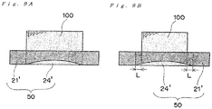
- the dummy solidified layer may be formed on only a part of the principal surface of the base plate.
- the dummy solidified layer 24' is formed such that the contour shape of the dummy solidified layer 24' is approximately the same as the contour shape of the bottom surface of the three-dimensional shaped object 100 to be manufactured. This can keep the time required for the formation of the dummy solidified layer 24' to the minimum, while giving the residual stress in the plate laminate body 50. Consequently, the light beam required for the formation of the dummy solidified layer 24' can be reduced, which leads to a more effective manufacturing of the three-dimensional shaped object 100.
- the contour shape of the dummy solidified layer 24' may be made larger than the contour shape of the bottom surface of the three-dimensional shaped object 100 to be manufactured (see Fig. 9B ).
- the dummy solidified layer 24' may be formed such that the contour shape of the dummy solidified layer 24' is larger by about 0.5 mm to about 10 mm than the contour shape of the bottom surface of the three-dimensional shaped object 100 to be manufactured. More specifically, the forming of the solidified layer 24' is performed such that the dimension of "L" shown in Fig. 9B is in the range of about 0.5 mm to about 10mm.
- the manufacturing method according to an embodiment of the present invention can provide various kinds of articles.
- the powder layer is a metal powder layer (i.e., inorganic powder layer) and thus the solidified layer corresponds to a sintered layer
- the three-dimensional shaped object obtained by the present invention can be used as a metal mold for a plastic injection molding, a press molding, a die casting, a casting or a forging.
- the powder layer is a resin powder layer (i.e., organic powder layer) and thus the solidified layer corresponds to a cured layer
- the three-dimensional shaped object obtained by the present invention can be used as a resin molded article.
Abstract
Description
- The present invention relates to a method for manufacturing a three-dimensional shaped object. More particularly, the present invention relates to a method for manufacturing a three-dimensional shaped object, in which a formation of a solidified layer is performed by an irradiation of a powder layer with a light beam.
- Heretofore, a method for manufacturing a three-dimensional shaped object by irradiating a powder material with a light beam has been known (such method can be generally referred to as a "selective laser sintering method") . The method can produce the three-dimensional shaped object by an alternate repetition of a powder-layer forming and a solidified-layer forming on the basis of the following (i) and (ii) :
- (i) forming a solidified layer by irradiating a predetermined portion of a powder layer with a light beam, thereby allowing a sintering of the predetermined portion of the powder or a melting and subsequent solidification of the predetermined portion; and
- (ii) forming another solidified layer by newly forming a powder layer on the formed solidified layer, followed by similarly irradiating the new powder layer with the light beam.
- This kind of the manufacturing technology makes it possible to produce the three-dimensional shaped object with its complicated contour shape in a short period of time. The three-dimensional shaped object can be used as a metal mold in a case where inorganic powder material (e.g., metal powder material) is used as the powder material. While on the other hand, the three-dimensional shaped object can also be used as various kinds of models or replicas in a case where organic powder material (e.g., resin powder material) is used as the powder material.
- Taking a case of the selective laser sintering method as an example wherein the metal powder is used as the powder material, and thus the three-dimensional shaped object produced therefrom is used as the metal mold, the selective laser sintering method will now be briefly described. As shown in
Figs. 10A-10C , asqueegee blade 23 is forced to move, and thereby apowder layer 22 with its predetermined thickness is formed on the base plate 21 (seeFig. 10A ). Then, a predetermined portion of thepowder layer 22 is irradiated with a light beam "L" to form asolidified layer 24 therefrom (seeFig. 10B ). Anotherpowder layer 22 is newly provided on thesolidified layer 24 thus formed, and is irradiated again with the light beam to form anothersolidified layer 24. In this way, the powder-layer forming and the solidified-layer forming are alternately repeated, allowing thesolidified layers 24 to be stacked with each other (seeFig. 10C ). Such alternate repetition of the powder-layer forming and the solidified-layer forming leads to a production of a three-dimensional shaped object with a plurality of thesolidified layers 24 integrally stacked therein. The lowermostsolidified layer 24 can be provided in a state of adhering to the surface of thebase plate 21. Therefore, there can be obtained an integration of the three-dimensional shaped object and thebase plate 21. The integrated "three-dimensional shaped object" and "base plate" can be used as the metal mold as they are. - PATENT DOCUMENT 1: Japanese Unexamined Patent Application Publication No.
H01-502890 - In the selective laser sintering method, the irradiated portion of the powder layer with the light beam transforms into the
solidified layer 24 through a sintering phenomenon or a melting and subsequent solidification phenomenon. Upon the formation of thesolidified layer 24 through such phenomenon, a shrinkage stress can occur due to a reduced void between particles of the powder material (Fig. 11A ). As a result, the integrated object of the three-dimensionalshaped obj ect 100 and the base plate 21 (i. e. , a platform for the object 100) becomes susceptible to a warp deformation (Fig. 11B ). This will bring concern that a desired shape of the three-dimensionalshaped object 100 cannot be provided. - Under these circumstances, the present invention has been created. That is, an object of the present invention is to provide a manufacturing method of a three-dimensional shaped object, the method being capable of reducing a warp deformation of the three-dimensional shaped object.
- In order to achieve the above object, an embodiment of the present invention provides a method for manufacturing a three-dimensional shaped object by alternate repetition of a powder-layer forming and a solidified-layer forming, the repetition comprising:
- (i) forming a solidified layer by irradiating a predetermined portion of a powder layer with a light beam, thereby allowing a sintering of the powder in the predetermined portion or a melting and subsequent solidification of the powder in the predetermined portion; and
- (ii) forming another solidified layer by newly forming a powder layer on the formed solidified layer, followed by irradiation of a predetermined portion of the newly formed powder layer with the light beam,
- In accordance with the manufacturing method of the present invention, the three-dimensional shaped object can be obtained with its warp deformation being reduced.
-
-
Fig. 1 is a cross-sectional view schematically showing a general concept of the present invention. -
Fig. 2 is a cross-sectional view schematically showing a preparation of a plate laminate body whereinFig. 2A shows a provision of base plate,Fig. 2B shows a warp deformation, andFig. 2C shows a flattening process. -
Fig. 3 is a cross-sectional view schematically showing a residual stress of a plate laminate body. -
Fig. 4 is a cross-sectional view schematically showing a reduced warp deformation of the shaped object by a plate laminate body. -
Fig. 5 is a cross-sectional view schematically showing a plate laminate body secured to a support table. -
Fig. 6 is a cross-sectional view schematically showing a manufacturing method of the present invention over time whereinFig. 6A shows a provision of base plate,Fig. 6B shows a warp deformation,Fig. 6C shows a flattening process,Fig. 6D shows a securing with respect to a support table, andFig. 6E shows a manufacturing of a three-dimensional shaped object. -
Fig. 7 is a graph showing a stress that can occur in a three-dimensional shaped object. -
Fig. 8 is a cross-sectional view schematically showing an embodiment of a blast machining. -
Fig. 9 is a cross-sectional view schematically showing a modified size of contour of a dummy solidified layer whereinFig. 9A shows the contour size of the dummy solidified layer is approximately the same as contour shape of three-dimensional shape object,Fig. 9B shows the contour size of the dummy solidified layer is larger than contour shape of three-dimensional shape object. -
Fig. 10 includes cross-sectional views schematically illustrating a laser-sintering/machining hybrid process for a selective laser sintering method whereinFig. 10A shows a powder-layer forming,Fig. 10B shows a solidified-layer forming, andFig. 10C shows a stacking of solidified layers. -
Fig. 11 includes cross-sectional views schematically illustrating a phenomenon of a warp deformation during a selective laser sintering method whereinFig. 11A shows a solidified layer with a shrinkage stress occurring therein, andFig. 11B shows the warp deformation of a three-dimensional shaped object. -
Fig. 12 is a perspective view schematically illustrating a construction of a laser-sintering/machining hybrid machine. -
Fig. 13 is a flow chart of general operations of a laser-sintering/machining hybrid machine. - The present invention according to an embodiment thereof will be described in more detail with reference to the accompanying drawings. It should be noted that configurations/forms and dimensional proportions in the drawings are merely for illustrative purposes, and thus not the same as those of the actual parts or elements.
- The term "powder layer" as used in this description and claims means a "metal powder layer made of a metal powder" or "resin powder layer made of a resin powder", for example. The term "predetermined portion of a powder layer" as used herein substantially means a portion of a three-dimensional shaped object to be manufactured. As such, a powder present in such predetermined portion is irradiated with a light beam, and thereby the powder undergoes a sintering or a melting and subsequent solidification to give a shape of a three-dimensional shaped object. Furthermore, the term "solidified layer" substantially means a "sintered layer" in a case where the powder layer is a metal powder layer, whereas term "solidified layer" substantially means a "cured layer" in a case where the powder layer is a resin powder layer.
- The directions of "upper" and "lower", which are directly or indirectly used herein, are ones based on a positional relationship between a plate laminate body and a three-dimensional shaped object at a point in time when the three-dimensional shaped object is manufactured. The side in which the manufactured three-dimensional shaped object is positioned with respect to the plate laminate body is "upper", and the opposite direction thereto is "lower".
- First of all, a selective laser sintering method, on which the manufacturing method of the present invention is based, will be described. By way of example, a laser-sintering/machining hybrid process wherein a machining is additionally carried out in the selective laser sintering method will be especially explained.
Figs. 10A-10C schematically show a process embodiment of the laser-sintering/machining hybrid.Figs. 12 and13 respectively show major constructions and operation flow regarding a laser-sintering/milling hybrid machine for enabling an execution of a machining process as well as the selective laser sintering method. - As shown in
Fig. 12 , the laser-sintering/millinghybrid machine 1 is provided with a powder layer former 2, a light-beam irradiator 3, and a machining means 4. - The powder layer former 2 is a means for forming a powder layer with its predetermined thickness through a supply of powder (e.g., a metal powder or a resin powder). The light-
beam irradiator 3 is a means for irradiating a predetermined portion of the powder layer with a light beam "L". The machining means 4 is a means for milling the side surface of the stacked solidified layers, i.e., the surface of the three-dimensional shaped object. - As shown in
Figs. 10A-10C , the powder layer former 2 is mainly composed of a powder table 25, asqueegee blade 23, a support table 20 and abase plate 21. The powder table 25 is a table capable of vertically elevating/descending in a "storage tank for powder material" 28 whose outer periphery is surrounded with awall 26. Thesqueegee blade 23 is a blade capable of horizontally moving to spread apowder 19 from the powder table 25 onto the forming table 20, and thereby forming apowder layer 22. The forming table 20 is a table capable of vertically elevating/descending in a formingtank 29 whose outer periphery is surrounded with awall 27. Thebase plate 21 is placed on the forming table 20 and serves as a platform of the three-dimensional shaped object. - As shown in
Fig. 12 , the light-beam irradiator 3 is mainly composed of alight beam generator 30 and agalvanometer mirror 31. Thelight beam generator 30 is a device for emitting a light beam "L". Thegalvanometer mirror 31 is a means for scanning an emitted light beam "L" onto thepowder layer 22, i.e., a scan means of the light beam "L". - As shown in
Fig. 12 , the machining means 4 is mainly composed of anend mill 40 and anactuator 41. Theend mill 40 is a cutting tool for milling the side surface of the stacked solidified layers, i.e., the surface of the three-dimensional shaped object. Theactuator 41 is a means for driving theend mill 40 to move toward the position to be milled. - Operations of the laser-sintering/milling
hybrid machine 1 will now be described in detail. As can be seen from the flowchart ofFig. 13 , the operations of the laser-sintering/millinghybrid machine 1 are mainly composed of a powder layer forming step (S1), a solidified layer forming step (S2), and a machining step (S3). The powder layer forming step (S1) is a step for forming thepowder layer 22. In the powder layer forming step (S1), first, the support table 20 is descended by Δt (S11), and thereby creating a level difference Δt between an upper surface of thebase plate 21 and an upper-edge plane of the formingtank 29. Subsequently, the powder table 25 is elevated by Δt, and then thesqueegee blade 23 is driven to move from thestorage tank 28 to the formingtank 29 in the horizontal direction, as shown inFig. 10A . This enables apowder 19 placed on the powder table 25 to be spread onto the base plate 21 (S12), while forming the powder layer 22 (S13). Examples of the powder for thepowder layer 22 include a "metal powder having a mean particle diameter of about 5 µm to 100 µm" and a "resin powder having a mean particle diameter of about 30 µm to 100 µm (e.g., a powder of nylon, polypropylene, ABS or the like". Following this step (i.e., the forming step for forming the powder layer 22), the solidified layer forming step (S2) is performed. The solidified layer forming step (S2) is a step for forming a solidifiedlayer 24 through the light beam irradiation. In the solidified layer forming step (S2), a light beam "L" is emitted from the light beam generator 30 (S21) . The emitted light beam "L" is scanned onto a predetermined portion of thepowder layer 22 by the galvanometer mirror 31 (S22) . The scanned light beam can cause the powder in the predetermined portion of thepowder layer 22 to be sintered or be melted and subsequently solidified, resulting in a formation of the solidified layer 24 (S23), as shown inFig. 10B . Examples of the light beam "L" include carbon dioxide gas laser, Nd:YAG laser, fiber laser, ultraviolet light, and the like. - The powder layer forming step (S1) and the solidified layer forming step (S2) are alternately repeated. This allows a plurality of the solidified layers 24 to be integrally stacked with each other, as shown in
Fig. 10C . - When the thickness of the stacked solidified
layers 24 reaches a predetermined value (S24), the machining step (S3) is initiated. The machining step (S3) is a step for milling the side surface of the stacked solidifiedlayers 24, i.e., the surface of the three-dimensional shaped object. The end mill 40 (seeFig. 10C andFig. 12 ) is actuated to initiate an execution of the machining step (S31) . For example, in a case where theend mill 40 has an effective milling length of 3 mm, a machining can be performed with a milling depth of 3 mm. Therefore, supposing that "Δt" is 0.05 mm, theend mill 40 is actuated when the formation of the sixty solidifiedlayers 24 is completed. Specifically, the side face of the stacked solidifiedlayers 24 is subjected to the surface machining (S32) through a movement of theend mill 40 driven by theactuator 41. Subsequent to the surface machining step (S3), it is judged whether or not the whole three-dimensional shaped object has been obtained (S33). When a desired three-dimensional shaped object has not yet been obtained, the step returns to the powder layer forming step (S1). Thereafter, the steps S1 through S3 are repeatedly performed again wherein the further stacking of the solidified layer and the further machining process therefor are similarly performed, which eventually leads to a provision of the desired three-dimensional shaped object. - The present invention is characterized by a platform for the three-dimensional shaped object to be manufactured in the selective laser sintering method.
- Specifically, the present invention makes use of a
plate laminate body 50 composed of at least two layers as a platform for a three-dimensional shaped object (see.Fig. 1 ). The use of theplate laminate body 50 can lead to a production of the three-dimensional shaped object with its warp deformation being reduced. - As shown in
Fig. 1 , theplate laminate body 50 comprises a dummy solidified layer 24' and a base plate 21' for shaped object. The term "plate laminate body" as used herein refers to a platform for a manufacturing of a three-dimensional shaped object, and in particular such term means the platform in a form of plate having a laminar structure. - As can be seen from
Fig. 1 , the laminar structure of theplate laminate body 50 has such a form that the base plate 21' and the dummy solidified layer 24' are stacked with each other. The base plate 21' corresponds to a conventional base plate 21 (seeFig. 10A ), but the base plate 21' is a plate which can have a residual stress in the interior thereof at a point in time before the three-dimensional shaped object is manufactured ("residual stress" herein will be later described in detail) . While on the other hand, the dummy solidified layer 24', which is a solidified layer provided on a principal surface of the base plate 21', is particularly a solidified layer provided on the principal surface which is opposite to a principal surface with which the three-dimensional shaped object (i.e., the solidifiedlayer 24 thereof) comes into contact (seeFig. 1 ). In other words, the dummy solidified layer 24' corresponds to a layer spaced via the base plate 21' with respect to the three-dimensional shaped object to be manufactured. - As such, the term "dummy" of the dummy solidified layer herein substantially refers to a "different" solidified layer which differs from the solidified layers of the three-dimensional shaped object to be manufactured on a platform.
- According to the manufacturing method of the present invention, the
plate laminate body 50 is a laminate body which has been once warp-deformed. Namely, according to the present invention, a warp deformation has been proactively caused in a precursor of the platform (i.e., plate laminate body) for the three-dimensional shaped object to be manufactured. In particular, it is preferred that theplate laminate body 50 is obtained by subjecting a warp-deformed laminate body 50' to a flattening process, the warp-deformed laminate body 50' being obtained by performing the forming of the dummy solidified layer 24'. SeeFig. 2 . Theplate laminate body 50 thus obtained is preferably provided prior to the manufacturing of the three-dimensional shaped object. - The provision of the
plate laminate body 50 will be described more specifically. First, the laminate body 50' is prepared by a forming of the dummy solidified layer 24' on the base plate 21' (seeFigs. 2A and 2B ). Similarly to the phenomenon as described with reference toFigs. 11A and 11B , a warp deformation is caused in the laminate body 50' upon the forming of the dummy solidified layer 24'. Subsequently, the laminate body 50' thus warp-deformed is subjected to a flattening process (seeFigs. 2B and 2C ). It is preferred that the flattening process is performed such that the laminate body 50' gets to be a suitable body for the "platform" in particular. The flattening process is a process for rendering a principal surface of the warp-deformed laminate body 50' flat. Through such "warp deformation" and "flattening process", theplate laminate body 50 suitable for use in the present invention can be eventually provided. - In order for the
plate laminate body 50 to have a more suitable form of "platform" for the manufacturing of the three-dimensional shaped object, it is preferred that opposed principal surfaces of the warp-deformed laminate body 50' are both subjected to a machining process as the flattening process. More specifically, it is preferred that the machining process is performed with respect to the laminate body 50' by removing a curved portion thereof attributed to the warp deformation, and thereby rendering the both principal surfaces of the body 50' flat. SeeFigs. 2B and 2C , for example. Such flattening process makes it possible for the both principal surfaces of the plate laminate body to have a substantially parallel relationship with each other. With the use of suchplate laminate body 50, the three-dimensional shaped object can be suitable manufactured on the substantially horizontal plane. - The
plate laminate body 50 has a stress remaining in the interior thereof since the body has once underwent the warp deformation. That is, theplate laminate body 50 can have a residual stress in the interior thereof. In particular, anoutward stress 14 can remain in the base plate 21' of theplate laminate body 50, as shown inFig. 3 . In this regard, the residual stress of theplate laminate body 50 is utilized upon the manufacturing of the three-dimensional shaped object so as to be against a stress which may be generated in the three-dimensional shaped object, and thereby the warp deformation of the three-dimensional shaped object can be reduced. - As shown in
Fig. 4 , theplate laminate body 50 is preferably placed such that "direction of theresidual stress 14 of theplate laminate body 50" and "direction of thestress 15 generated in the three-dimensionalshaped object 100" are opposite to each other. The reason for this is that an offset effect between these stresses (14, 15) can be brought about. This means that the placing of theplate laminate body 50 as shown inFig. 4 allows thestress 15 generated in the three-dimensionalshaped object 100 to be mitigated by theresidual stress 14 of theplate laminate body 50, which leads to a suitable production of the three-dimensionalshaped object 100 with the warp deformation thereof being reduced. - In order to render the directions opposite to each other regarding the "direction of the
residual stress 14 of theplate laminate body 50" and the "direction of thestress 15 generated in the three-dimensionalshaped object 100", theplate laminate body 50 is preferably placed such that one of the principal surfaces of theplate laminate body 50, which is provided with no dummy solidified layer 24', faces upward. In other words, supposing that a dummy-side principal surface of the base plate 21', on which the formed dummy solidified layer 24' is provided, is regarded as "front principal surface", the placing of theplate laminate body 50 is preferably such that the back principal surface of the base plate 21' faces upward. - Taking a case as an example wherein the three-dimensional shaped object is manufactured by the laser-sintering/milling hybrid machine 1 (
Fig. 10 as well asFigs. 12 and13 ), it is preferred that theplate laminate body 50 is placed onto a support table 20 as shown inFig. 5 . In this case, an upper exposed surface of theplate laminate body 50 placed on the support table 20 corresponds to the above "back principal surface". It is thus preferred that, when the powder-layer forming and the solidified-layer forming are performed on theplate laminate body 50 secured to the support table 20, the securing of theplate laminate body 50 with respect to the support table 20 is such that the dummy solidified layer 24' is positioned between the base plate 21' and the support table 20. As shown inFig. 5 , theresidual stress 14 in theplate laminate body 50 secured to the support table 20 has a direction of "outward", whereas the stress which can be generated in the three-dimensionalshaped object 100 manufactured on suchplate laminate body 50 has a direction of "inward". As a result, an offset effect between these stresses can be brought about, which leads to a suitable production of the three-dimensionalshaped object 100 while the warp deformation thereof is reduced. - Now, the manufacturing method according to one embodiment of the present invention over time will be described below.
- First, the base plate 21' for the shaped object is provided as shown in
Fig. 6A . The base plate 21' for the shaped object may be abase plate 21 used conventionally in the selective laser sintering method (seeFig. 10A ). For example in a case where a metal powder is used as the powder so as to form a sintered layer as the solidified layer (i.e., sintered layer made of an iron-based material), the base plate 21' is preferably made of at least one material selected from the group consisting of a steel, a hardmetal (cemented carbide), a high-speed tool steel, an alloy tool steel, a stainless steel, and a carbon steel for machine construction. It is preferred that the base plate 21' typically has a flattened form as a whole because of "plate". The specific form of the base plate 21' is not particularly limited as long as it serves as a platform for the three-dimensional shaped object. Thus, the form of the base plate 21' is not only a cuboid form, but also may be a disc form, a polygonal column form or the like. The principal surface of the base plate 21' is generally required to have a larger size than that of the bottom surface of the three-dimensional shaped object. For example, the principal surface of the base plate 21' has the larger size in 110% to 200% of that of the bottom surface of the shaped object. The thickness of the base plate 21', i.e., a base plate dimension along the stacking direction in the manufacturing of the three-dimensional shaped object to be manufactured may be for example in the range of about 10 mm to about 70 mm. - The base plate 21' itself is subjected to a warp deformation through the forming of the dummy solidified layer 24' (see
Figs. 6A and 6B ). Specifically, first, a powder layer is formed on the base plate 21', and then the dummy solidified layer 24' is formed by irradiation of the powder layer with the light beam. - The powder material to be used for the formation of the dummy solidified layer 24' may be the same as the powder material used for the subsequent manufacturing of the three-dimensional shaped object. For example, the metal powder with its mean particle diameter of about 5 µm to 100 µm may be used. By the use of such powder material, a powder layer for the dummy solidified layer 24' can be formed. The resulting powder layer is wholly irradiated with the light beam. This causes a sintering of the powder material or a melting and subsequent solidification of the powder material, and thereby the dummy solidified layer 24' is formed. The thickness of the dummy solidified layer 24' may be in the range of 0.1 mm to 10 mm, for example. In this regard, the dummy solidified layer 24' may be widely formed such that the dummy solidified layer 24' covers the whole principal surface of the base plate 21', as shown in
Fig. 6B . - Upon the forming of the dummy solidified layer 24 ', a shrinkage stress can occur due to a reduced void between particles of the powder material, and thereby causing the dummy solidified layer 24' and the base plate 21' bonded thereto to be warp-deformed. This means that the warp deformation occurs in the laminate body 50' composed of the dummy solidified layer 24' and the base plate 21'. The laminate body 50' has an
outward stress 14 that can remain in the base plate 21' due to the warp deformation (seeFig. 6B ). In particular, supposing that a dummy-side principal surface of the base plate 21', on which the formed dummy solidified layer 24' is provided, is regarded as "front principal surface", thestress 14, which acts in an outward direction, can remain in the vicinity of the back principal surface of the base plate 21'. - A flattening process is performed with respect to the warp-deformed laminate body 50' (see
Figs. 6B and 6C ). More specifically, a machining process is performed with respect to the laminate body 50' by removing its curved portion attributed to the warp deformation, and thereby providing the flat surface of the laminate body. As can be seen fromFigs. 6B and 6C , it is preferred that the opposed principal surfaces of the laminate body 50' are both subjected to the machining process. This makes it possible for the both principal surfaces of theplate laminate body 50 to be parallel with each other, which leads to a suitable provision of theplate laminate body 50 using as the platform for the three-dimensional shaped object. - For the flattening process, a machining means may be used. The machining means may be any suitable one as long as it performs a surface machining treatment. For example, the machining means may be a numerical control (NC: Numerical Control) machine tool or those analogous thereto. Specifically, it is preferred that the machining means is a machining center (MC) whose milling tool (end mill) is automatically exchangeable. As the end mill, for example, a twin bladed ball end mill made of a superhard material is mainly used. A square end mill, a radius end mill or the like may also be used in some cases. In order to improve the flatness of the principal surfaces of the laminate body 50', a flat grinding process may be additionally performed by a surface grinding machine or the like.
- The
plate laminate body 50 obtained through the above (1) to (3) is subjected to an inversion. That is, theplate laminate body 50, which is one obtained by the flattening process of the warp-deformed body, is flipped so that the upper and lower principal surfaces of the plate laminate body are inverted with each other (seeFigs. 6C and 6D ). More specifically, theplate laminate body 50 with the dummy solidified layer 24' being positioned on the upper side, whereas the base plate 21' being positioned on the lower side is flipped such that the inversion thereof is given. Supposing that a dummy-side principal surface of the base plate 21', on which the formed dummy solidified layer 24' is provided, is regarded as "front principal surface", the inversion of theplate laminate body 50 is performed such that the back principal surface of the base plate 21' gets to face upward. - As shown in
Fig. 6D , it is preferred that, through the inversion of the plate laminate body, theplate laminate body 50 is secured with respect to the support table 20 such that the dummy solidified layer 24' is positioned between the base plate 21' and the support table 20. This allows theresidual stress 14 in theplate laminate body 50 secured to the support table 20 to have a direction of "outward", whereas the stress which can be generated in the three-dimensionalshaped object 100 to be manufactured on theplate laminate body 50 has a direction of "inward" (seeFigs. 6E ). As a result, theresidual stress 14 of theplate laminate body 50 can suitably act against theinward stress 15 such that the offset effect between these stresses can be given at a point in time during the three-dimensionalshaped object 100 is manufactured. - After the securing of the
plate laminate body 50, the manufacturing of the three-dimensionalshaped object 100 is initiated using the securedplate laminate body 50 as the platform for the shaped object. As can be seen fromFigs. 6C and 6E , the three-dimensionalshaped object 100 is manufactured on the "back principal surface" of the base plate 21' of theplate laminate body 50. - The direction of the
stress 15 that can be generated in the three-dimensionalshaped object 100 to be manufactured on theplate laminate body 50 is "inward". While on the other hand, the direction of theresidual stress 14 in theplate laminate body 50 is "outward" due to the warp deformation of the body. That is, thestress 15 generated upon the manufacturing of the three-dimensionalshaped object 100 and theresidual stress 14 of theplate laminate body 50 have the opposite directions to each other. This enables thestress 15 generated upon the manufacturing of the three-dimensionalshaped object 100 to be mitigated by theresidual stress 14 of theplate laminate body 50, which leads to a reduction in the warp deformation of the three-dimensionalshaped object 100. - The inventors of the present application have found that the
stress 15 generated during the manufacturing of the three-dimensionalshaped object 100 is larger at an earlier stage of the manufacturing (seeFig. 7 ). More specifically, as can be seen fromFig. 7 , the large stress occurs especially at the bottom surface of the three-dimensionalshaped object 100. This means that there is a large stress generated especially at a boundary region between the three-dimensionalshaped object 100 and the platform therefor. - In this regard, the use of the
plate laminate body 50 as the platform according to the manufacturing method of the present invention can effectively affect the stress generated in the three-dimensional shaped object at the earlier stage of the manufacturing thereof More specifically, although the larger stress occurs especially at the bottom surface of the three-dimensional shaped object, such bottom surface is provided with theplate laminate body 50, which can effectively reduce thestress 15 of the three-dimensional shaped object by theresidual stress 14 of the plate laminate body 50 (seeFig. 4 ) . - While several embodiments of the present invention have been hereinbefore described as a typical example, various specific other embodiments can also be possible.
- The manufacturing method of the present invention makes use of the residual stress of the plate laminate body to act against the stress that can be generated in the three-dimensional shaped object. It is, however, conceivable that there may be such a plate laminate body that the residual stress thereof is smaller than the stress of the three-dimensional shaped object.
- In this case, it is preferred that the plate laminate body is subjected to a blast machining. Specifically, it is preferred that the blast machining is additionally performed with respect to the "back principal surface" of the base plate 21' of the
plate laminate body 50 obtained after the flattening process (seeFig. 8 ). - The blast machining of the
plate laminate body 50 can provide such an effect that theoutward stress 14 is increased in thelaminate body 50. That is, thestress 14 for acting against the stress of the three-dimensional shaped object becomes larger. This means that theresidual stress 14 of theplate laminate body 50 can be suitably adjusted by the blast machining, which leads to a more effective reduction in the warp deformation of the three-dimensional shaped object. - With respect to the blast machining, it can also increase a surface roughness of the plate laminate body. The increased surface roughness leads to an increase in a contact area between the plate laminate body and the three-dimensional shaped object manufactured thereon. Thus, the blast machining of the plate laminate body can improve a bonding strength between the plate laminate body and the three-dimensional shaped object. This can provide such an effect that a structure strength is increased in the integration of the plate laminate body and the three-dimensional shaped object.
- When the plate laminate body is prepared, the dummy solidified layer may be formed on only a part of the principal surface of the base plate. For example, as shown in
Fig. 9A , the dummy solidified layer 24' is formed such that the contour shape of the dummy solidified layer 24' is approximately the same as the contour shape of the bottom surface of the three-dimensionalshaped object 100 to be manufactured. This can keep the time required for the formation of the dummy solidified layer 24' to the minimum, while giving the residual stress in theplate laminate body 50. Consequently, the light beam required for the formation of the dummy solidified layer 24' can be reduced, which leads to a more effective manufacturing of the three-dimensionalshaped object 100. - In a case where the residual stress required for the
plate laminate body 50 is insufficient in the embodiment ofFig. 9A , then the contour shape of the dummy solidified layer 24' may be made larger than the contour shape of the bottom surface of the three-dimensionalshaped object 100 to be manufactured (seeFig. 9B ). The reason for this is that the larger the size of the dummy solidified layer 24' becomes, the greater theresidual stress 14 of theplate laminate body 50 becomes. By way of example, the dummy solidified layer 24' may be formed such that the contour shape of the dummy solidified layer 24' is larger by about 0.5 mm to about 10 mm than the contour shape of the bottom surface of the three-dimensionalshaped object 100 to be manufactured. More specifically, the forming of the solidified layer 24' is performed such that the dimension of "L" shown inFig. 9B is in the range of about 0.5 mm to about 10mm. - Although some embodiments of the present invention have been hereinbefore described, these are regarded merely as typical ones, and thus the present invention is not limited to such embodiments. It will be readily appreciated by those skilled in the art that various modified embodiments are possible without departing from the scope of the present invention.
- It should be noted that the present invention as described above includes the following suitable aspects:
- The first aspect: A method for manufacturing a three-dimensional shaped object by alternate repetition of a powder-layer forming and a solidified-layer forming, the repetition comprising:
- (i) forming a solidified layer by irradiating a predetermined portion of a powder layer with a light beam, thereby allowing a sintering of the powder in the predetermined portion or a melting and subsequent solidification of the powder in the predetermined portion; and
- (ii) forming another solidified layer by newly forming a powder layer on the formed solidified layer, followed by irradiation of a predetermined portion of the newly formed powder layer with the light beam,
the plate laminate body is such that the dummy solidified layer is formed on one of principal surfaces of the base plate, whereas the three-dimensional shaped object is manufactured on the other of the principal surfaces of the base plate. - The second aspect: The method according to the first aspect, wherein the plate laminate body is obtained by subjecting a warp-deformed laminate body to a flattening process, the warp-deformed laminate body being obtained by performing the forming of the dummy solidified layer.
- The third aspect: The method according to the second aspect, wherein, as the flattening process, opposed principal surfaces of the warp-deformed laminate body are both subjected to a machining process.
- The fourth aspect: The method according to the second or third aspect, wherein the plate laminate body is subjected to a blast machining.
- The fifth aspect: The method according to any one of the first to fourth aspects, wherein the powder-layer forming and the solidified-layer forming are performed on the plate laminate body secured to a support table, and
- The manufacturing method according to an embodiment of the present invention can provide various kinds of articles. For example, in a case where the powder layer is a metal powder layer (i.e., inorganic powder layer) and thus the solidified layer corresponds to a sintered layer, the three-dimensional shaped object obtained by the present invention can be used as a metal mold for a plastic injection molding, a press molding, a die casting, a casting or a forging. While on the other hand in a case where the powder layer is a resin powder layer (i.e., organic powder layer) and thus the solidified layer corresponds to a cured layer, the three-dimensional shaped object obtained by the present invention can be used as a resin molded article.
- The present application claims the right of priority of Japanese Patent Application No.
2016-045893 (filed on March 9, 2016 -
- 50
- Plate laminate body
- 21'
- Base plate
- 24'
- Dummy solidified layer
- 100
- Three-dimensional shaped object
- 20
- Support table
the dummy solidified layer is formed on one of principal surfaces of the base plate, whereas the three-dimensional shaped object is manufactured on the other of the principal surfaces of the base plate.
Claims (5)
- A method for manufacturing a three-dimensional shaped object by alternate repetition of a powder-layer forming and a solidified-layer forming, the repetition comprising:(i) forming' a solidified layer by irradiating a predetermined portion of a powder layer with a light beam, thereby allowing a sintering of the powder in the predetermined portion or a melting and subsequent solidification of the powder; and(ii) forming another solidified layer by newly forming a powder layer on the formed solidified layer, followed by irradiation of a predetermined portion of the newly formed powder layer with the light beam,wherein, as a platform for the three-dimensional shaped object, a plate laminate body comprising a dummy solidified layer and a base plate for the shaped object is used, and
the plate laminate body is such that the dummy solidified layer is formed on one of principal surfaces of the base plate, whereas the three-dimensional shaped object is manufactured on the other of the principal surfaces of the base plate. - The method according to claim 1, wherein the plate laminate body is obtained by subjecting a warp-deformed laminate body to a flattening process, the warp-deformed laminate body being obtained by performing the forming of the dummy solidified layer.
- The method according to claim 2, wherein, as the flattening process, opposed principal surfaces of the warp-deformed laminate body are both subjected to a machining process.
- The method according to claim 2, wherein the plate laminate body is subjected to a blast machining.
- The method according to claim 1, wherein the powder-layer forming and the solidified-layer forming are performed using the plate laminate body secured to a support table, and
the securing of the plate laminate body with respect to the support table is such that the dummy solidified layer is positioned between the base plate and the support table.
Applications Claiming Priority (2)
| Application Number | Priority Date | Filing Date | Title |
|---|---|---|---|
| JP2016045893A JP6643631B2 (en) | 2016-03-09 | 2016-03-09 | Manufacturing method of three-dimensional shaped object |
| PCT/JP2017/009190 WO2017154965A1 (en) | 2016-03-09 | 2017-03-08 | Three-dimensional molded object production method |
Publications (3)
| Publication Number | Publication Date |
|---|---|
| EP3427870A1 true EP3427870A1 (en) | 2019-01-16 |
| EP3427870A4 EP3427870A4 (en) | 2019-01-16 |
| EP3427870B1 EP3427870B1 (en) | 2020-01-01 |
Family
ID=59789556
Family Applications (1)
| Application Number | Title | Priority Date | Filing Date |
|---|---|---|---|
| EP17763305.4A Active EP3427870B1 (en) | 2016-03-09 | 2017-03-08 | Three-dimensional molded object production method |
Country Status (6)
| Country | Link |
|---|---|
| US (1) | US10821663B2 (en) |
| EP (1) | EP3427870B1 (en) |
| JP (1) | JP6643631B2 (en) |
| KR (1) | KR102145781B1 (en) |
| CN (1) | CN108778575A (en) |
| WO (1) | WO2017154965A1 (en) |
Cited By (1)
| Publication number | Priority date | Publication date | Assignee | Title |
|---|---|---|---|---|
| US20200306887A1 (en) * | 2019-03-25 | 2020-10-01 | Airbus Operations Limited | Fixture for additive manufacturing and heat treatment |
Families Citing this family (6)
| Publication number | Priority date | Publication date | Assignee | Title |
|---|---|---|---|---|
| JP7087430B2 (en) * | 2018-02-14 | 2022-06-21 | セイコーエプソン株式会社 | Manufacturing method of 3D model and 3D modeling device |
| JP6676688B2 (en) | 2018-04-06 | 2020-04-08 | 株式会社ソディック | Manufacturing method of three-dimensional objects |
| US10780498B2 (en) * | 2018-08-22 | 2020-09-22 | General Electric Company | Porous tools and methods of making the same |
| JP2022541108A (en) * | 2019-06-29 | 2022-09-22 | 浙江大学 | 3D printing method of air core configuration of complex curved surface |
| JP7008669B2 (en) * | 2019-09-09 | 2022-01-25 | 日本電子株式会社 | 3D laminated modeling device and 3D laminated modeling method |
| CN115213427A (en) * | 2022-07-19 | 2022-10-21 | 季华实验室 | Additive manufacturing method and product |
Family Cites Families (11)
| Publication number | Priority date | Publication date | Assignee | Title |
|---|---|---|---|---|
| US4863538A (en) | 1986-10-17 | 1989-09-05 | Board Of Regents, The University Of Texas System | Method and apparatus for producing parts by selective sintering |
| DE3750931T3 (en) | 1986-10-17 | 1999-12-02 | Univ Texas | METHOD AND DEVICE FOR PRODUCING MOLDED BODIES BY PARTIAL INTERSTERING. |
| CN101541511B (en) * | 2007-05-30 | 2011-12-21 | 松下电工株式会社 | Laminate shaping apparatus |
| JP5061062B2 (en) * | 2008-08-08 | 2012-10-31 | パナソニック株式会社 | Manufacturing method of three-dimensional shaped object |
| GB0819935D0 (en) * | 2008-10-30 | 2008-12-10 | Mtt Technologies Ltd | Additive manufacturing apparatus and method |
| JP5519766B2 (en) * | 2010-02-17 | 2014-06-11 | パナソニック株式会社 | Manufacturing method of three-dimensional shaped object and three-dimensional shaped object |
| JP5535121B2 (en) | 2011-04-19 | 2014-07-02 | パナソニック株式会社 | Manufacturing method of three-dimensional shaped object |
| JP5895172B2 (en) * | 2012-02-09 | 2016-03-30 | パナソニックIpマネジメント株式会社 | Manufacturing method of three-dimensional shaped object |
| GB2500412A (en) | 2012-03-21 | 2013-09-25 | Eads Uk Ltd | Build Plate for an additive manufacturing process |
| US10413970B2 (en) | 2014-07-30 | 2019-09-17 | Panasonic Intellectual Property Management Co., Ltd. | Method for manufacturing three-dimensional shaped object and three-dimensional shaped object |
| GB201806369D0 (en) * | 2018-04-19 | 2018-06-06 | Rolls Royce Plc | Stress relieve for additive layer manufacturing |
-
2016
- 2016-03-09 JP JP2016045893A patent/JP6643631B2/en active Active
-
2017
- 2017-03-08 WO PCT/JP2017/009190 patent/WO2017154965A1/en active Application Filing
- 2017-03-08 CN CN201780015568.2A patent/CN108778575A/en active Pending
- 2017-03-08 EP EP17763305.4A patent/EP3427870B1/en active Active
- 2017-03-08 US US16/083,362 patent/US10821663B2/en active Active
- 2017-03-08 KR KR1020187025409A patent/KR102145781B1/en active IP Right Grant
Cited By (3)
| Publication number | Priority date | Publication date | Assignee | Title |
|---|---|---|---|---|
| US20200306887A1 (en) * | 2019-03-25 | 2020-10-01 | Airbus Operations Limited | Fixture for additive manufacturing and heat treatment |
| CN111730056A (en) * | 2019-03-25 | 2020-10-02 | 空中客车营运有限公司 | Fixing device for additive manufacturing and heat treatment |
| EP3718663A1 (en) * | 2019-03-25 | 2020-10-07 | Airbus Operations Limited | Fixture for additive manufacturing and heat treatment |
Also Published As
| Publication number | Publication date |
|---|---|
| KR102145781B1 (en) | 2020-08-19 |
| WO2017154965A1 (en) | 2017-09-14 |
| US10821663B2 (en) | 2020-11-03 |
| EP3427870A4 (en) | 2019-01-16 |
| EP3427870B1 (en) | 2020-01-01 |
| JP6643631B2 (en) | 2020-02-12 |
| KR20180111912A (en) | 2018-10-11 |
| CN108778575A (en) | 2018-11-09 |
| JP2017160485A (en) | 2017-09-14 |
| US20190091923A1 (en) | 2019-03-28 |
Similar Documents
| Publication | Publication Date | Title |
|---|---|---|
| US10821663B2 (en) | Method for manufacturing three-dimensional shaped object | |
| US9592554B2 (en) | Method for manufacturing three-dimensional shaped object | |
| US10022797B2 (en) | Method for manufacturing three-dimensional shaped object and three-dimensional shaped object | |
| US9687911B2 (en) | Method for manufacturing three-dimensional shaped object | |
| JP5119123B2 (en) | Manufacturing method of three-dimensional shaped object | |
| KR101666102B1 (en) | Method for manufacturing three-dimensional molding | |
| US10000021B2 (en) | Method for manufacturing three-dimensional shaped object and three-dimensional shaped object obtained by the same | |
| WO2015133138A1 (en) | Method for producing three-dimensionally shaped object | |
| CN107848212B (en) | Method for manufacturing three-dimensional shaped object | |
| KR20160019558A (en) | Production method and production device for three-dimensionally shaped molded object | |
| KR20150056661A (en) | Production method for three-dimensionally shaped molded object | |
| US20180200795A1 (en) | Method for manufacturing three-dimensional shaped object and three-dimensional shaped object | |
| JP5612530B2 (en) | Manufacturing method of three-dimensional shaped object | |
| US20190344348A1 (en) | Method for manufacturing three-dimensional shaped object | |
| US10898953B2 (en) | Method for manufacturing three-dimensional shaped object | |
| JP2007077443A (en) | Method for manufacturing three-dimensional structure | |
| JP2023183596A (en) | Metal laminate shaping method |
Legal Events
| Date | Code | Title | Description |
|---|---|---|---|
| STAA | Information on the status of an ep patent application or granted ep patent |
Free format text: STATUS: THE INTERNATIONAL PUBLICATION HAS BEEN MADE |
|
| PUAI | Public reference made under article 153(3) epc to a published international application that has entered the european phase |
Free format text: ORIGINAL CODE: 0009012 |
|
| STAA | Information on the status of an ep patent application or granted ep patent |
Free format text: STATUS: REQUEST FOR EXAMINATION WAS MADE |
|
| 17P | Request for examination filed |
Effective date: 20180906 |
|
| A4 | Supplementary search report drawn up and despatched |
Effective date: 20181112 |
|
| AK | Designated contracting states |
Kind code of ref document: A1 Designated state(s): AL AT BE BG CH CY CZ DE DK EE ES FI FR GB GR HR HU IE IS IT LI LT LU LV MC MK MT NL NO PL PT RO RS SE SI SK SM TR |
|
| AX | Request for extension of the european patent |
Extension state: BA ME |
|
| DAV | Request for validation of the european patent (deleted) | ||
| DAX | Request for extension of the european patent (deleted) | ||
| REG | Reference to a national code |
Ref country code: DE Ref legal event code: R079 Ref document number: 602017010481 Country of ref document: DE Free format text: PREVIOUS MAIN CLASS: B22F0003160000 Ipc: B22F0003105000 |
|
| GRAP | Despatch of communication of intention to grant a patent |
Free format text: ORIGINAL CODE: EPIDOSNIGR1 |
|
| STAA | Information on the status of an ep patent application or granted ep patent |
Free format text: STATUS: GRANT OF PATENT IS INTENDED |
|
| INTG | Intention to grant announced |
Effective date: 20190724 |
|
| RIC1 | Information provided on ipc code assigned before grant |
Ipc: B33Y 30/00 20150101ALI20190712BHEP Ipc: B29C 64/245 20170101ALI20190712BHEP Ipc: B33Y 10/00 20150101ALI20190712BHEP Ipc: B22F 3/105 20060101AFI20190712BHEP |
|
| RIN1 | Information on inventor provided before grant (corrected) |
Inventor name: MORI, MIKIO Inventor name: ABE, SATOSHI Inventor name: FUWA, ISAO |
|
| GRAS | Grant fee paid |
Free format text: ORIGINAL CODE: EPIDOSNIGR3 |
|
| GRAA | (expected) grant |
Free format text: ORIGINAL CODE: 0009210 |
|
| STAA | Information on the status of an ep patent application or granted ep patent |
Free format text: STATUS: THE PATENT HAS BEEN GRANTED |
|
| AK | Designated contracting states |
Kind code of ref document: B1 Designated state(s): AL AT BE BG CH CY CZ DE DK EE ES FI FR GB GR HR HU IE IS IT LI LT LU LV MC MK MT NL NO PL PT RO RS SE SI SK SM TR |
|
| REG | Reference to a national code |
Ref country code: GB Ref legal event code: FG4D |
|
| REG | Reference to a national code |
Ref country code: CH Ref legal event code: EP Ref country code: AT Ref legal event code: REF Ref document number: 1219153 Country of ref document: AT Kind code of ref document: T Effective date: 20200115 |
|
| REG | Reference to a national code |
Ref country code: IE Ref legal event code: FG4D |
|
| REG | Reference to a national code |
Ref country code: DE Ref legal event code: R096 Ref document number: 602017010481 Country of ref document: DE |
|
| PGFP | Annual fee paid to national office [announced via postgrant information from national office to epo] |
Ref country code: DE Payment date: 20200320 Year of fee payment: 4 |
|
| REG | Reference to a national code |
Ref country code: NL Ref legal event code: MP Effective date: 20200101 |
|
| REG | Reference to a national code |
Ref country code: LT Ref legal event code: MG4D |
|
| PG25 | Lapsed in a contracting state [announced via postgrant information from national office to epo] |
Ref country code: LT Free format text: LAPSE BECAUSE OF FAILURE TO SUBMIT A TRANSLATION OF THE DESCRIPTION OR TO PAY THE FEE WITHIN THE PRESCRIBED TIME-LIMIT Effective date: 20200101 Ref country code: NL Free format text: LAPSE BECAUSE OF FAILURE TO SUBMIT A TRANSLATION OF THE DESCRIPTION OR TO PAY THE FEE WITHIN THE PRESCRIBED TIME-LIMIT Effective date: 20200101 Ref country code: CZ Free format text: LAPSE BECAUSE OF FAILURE TO SUBMIT A TRANSLATION OF THE DESCRIPTION OR TO PAY THE FEE WITHIN THE PRESCRIBED TIME-LIMIT Effective date: 20200101 Ref country code: PT Free format text: LAPSE BECAUSE OF FAILURE TO SUBMIT A TRANSLATION OF THE DESCRIPTION OR TO PAY THE FEE WITHIN THE PRESCRIBED TIME-LIMIT Effective date: 20200527 Ref country code: NO Free format text: LAPSE BECAUSE OF FAILURE TO SUBMIT A TRANSLATION OF THE DESCRIPTION OR TO PAY THE FEE WITHIN THE PRESCRIBED TIME-LIMIT Effective date: 20200401 Ref country code: FI Free format text: LAPSE BECAUSE OF FAILURE TO SUBMIT A TRANSLATION OF THE DESCRIPTION OR TO PAY THE FEE WITHIN THE PRESCRIBED TIME-LIMIT Effective date: 20200101 Ref country code: RS Free format text: LAPSE BECAUSE OF FAILURE TO SUBMIT A TRANSLATION OF THE DESCRIPTION OR TO PAY THE FEE WITHIN THE PRESCRIBED TIME-LIMIT Effective date: 20200101 |
|
| PG25 | Lapsed in a contracting state [announced via postgrant information from national office to epo] |
Ref country code: LV Free format text: LAPSE BECAUSE OF FAILURE TO SUBMIT A TRANSLATION OF THE DESCRIPTION OR TO PAY THE FEE WITHIN THE PRESCRIBED TIME-LIMIT Effective date: 20200101 Ref country code: HR Free format text: LAPSE BECAUSE OF FAILURE TO SUBMIT A TRANSLATION OF THE DESCRIPTION OR TO PAY THE FEE WITHIN THE PRESCRIBED TIME-LIMIT Effective date: 20200101 Ref country code: GR Free format text: LAPSE BECAUSE OF FAILURE TO SUBMIT A TRANSLATION OF THE DESCRIPTION OR TO PAY THE FEE WITHIN THE PRESCRIBED TIME-LIMIT Effective date: 20200402 Ref country code: IS Free format text: LAPSE BECAUSE OF FAILURE TO SUBMIT A TRANSLATION OF THE DESCRIPTION OR TO PAY THE FEE WITHIN THE PRESCRIBED TIME-LIMIT Effective date: 20200501 Ref country code: SE Free format text: LAPSE BECAUSE OF FAILURE TO SUBMIT A TRANSLATION OF THE DESCRIPTION OR TO PAY THE FEE WITHIN THE PRESCRIBED TIME-LIMIT Effective date: 20200101 Ref country code: BG Free format text: LAPSE BECAUSE OF FAILURE TO SUBMIT A TRANSLATION OF THE DESCRIPTION OR TO PAY THE FEE WITHIN THE PRESCRIBED TIME-LIMIT Effective date: 20200401 |
|
| REG | Reference to a national code |
Ref country code: DE Ref legal event code: R097 Ref document number: 602017010481 Country of ref document: DE |
|
| PG25 | Lapsed in a contracting state [announced via postgrant information from national office to epo] |
Ref country code: EE Free format text: LAPSE BECAUSE OF FAILURE TO SUBMIT A TRANSLATION OF THE DESCRIPTION OR TO PAY THE FEE WITHIN THE PRESCRIBED TIME-LIMIT Effective date: 20200101 Ref country code: SM Free format text: LAPSE BECAUSE OF FAILURE TO SUBMIT A TRANSLATION OF THE DESCRIPTION OR TO PAY THE FEE WITHIN THE PRESCRIBED TIME-LIMIT Effective date: 20200101 Ref country code: DK Free format text: LAPSE BECAUSE OF FAILURE TO SUBMIT A TRANSLATION OF THE DESCRIPTION OR TO PAY THE FEE WITHIN THE PRESCRIBED TIME-LIMIT Effective date: 20200101 Ref country code: RO Free format text: LAPSE BECAUSE OF FAILURE TO SUBMIT A TRANSLATION OF THE DESCRIPTION OR TO PAY THE FEE WITHIN THE PRESCRIBED TIME-LIMIT Effective date: 20200101 Ref country code: ES Free format text: LAPSE BECAUSE OF FAILURE TO SUBMIT A TRANSLATION OF THE DESCRIPTION OR TO PAY THE FEE WITHIN THE PRESCRIBED TIME-LIMIT Effective date: 20200101 Ref country code: SK Free format text: LAPSE BECAUSE OF FAILURE TO SUBMIT A TRANSLATION OF THE DESCRIPTION OR TO PAY THE FEE WITHIN THE PRESCRIBED TIME-LIMIT Effective date: 20200101 Ref country code: MC Free format text: LAPSE BECAUSE OF FAILURE TO SUBMIT A TRANSLATION OF THE DESCRIPTION OR TO PAY THE FEE WITHIN THE PRESCRIBED TIME-LIMIT Effective date: 20200101 |
|
| REG | Reference to a national code |
Ref country code: CH Ref legal event code: PL |
|
| PLBE | No opposition filed within time limit |
Free format text: ORIGINAL CODE: 0009261 |
|
| STAA | Information on the status of an ep patent application or granted ep patent |
Free format text: STATUS: NO OPPOSITION FILED WITHIN TIME LIMIT |
|
| REG | Reference to a national code |
Ref country code: AT Ref legal event code: MK05 Ref document number: 1219153 Country of ref document: AT Kind code of ref document: T Effective date: 20200101 |
|
| 26N | No opposition filed |
Effective date: 20201002 |
|
| REG | Reference to a national code |
Ref country code: BE Ref legal event code: MM Effective date: 20200331 |
|
| PG25 | Lapsed in a contracting state [announced via postgrant information from national office to epo] |
Ref country code: LU Free format text: LAPSE BECAUSE OF NON-PAYMENT OF DUE FEES Effective date: 20200308 |
|
| PG25 | Lapsed in a contracting state [announced via postgrant information from national office to epo] |
Ref country code: CH Free format text: LAPSE BECAUSE OF NON-PAYMENT OF DUE FEES Effective date: 20200331 Ref country code: AT Free format text: LAPSE BECAUSE OF FAILURE TO SUBMIT A TRANSLATION OF THE DESCRIPTION OR TO PAY THE FEE WITHIN THE PRESCRIBED TIME-LIMIT Effective date: 20200101 Ref country code: IT Free format text: LAPSE BECAUSE OF FAILURE TO SUBMIT A TRANSLATION OF THE DESCRIPTION OR TO PAY THE FEE WITHIN THE PRESCRIBED TIME-LIMIT Effective date: 20200101 Ref country code: IE Free format text: LAPSE BECAUSE OF NON-PAYMENT OF DUE FEES Effective date: 20200308 Ref country code: FR Free format text: LAPSE BECAUSE OF NON-PAYMENT OF DUE FEES Effective date: 20200331 Ref country code: LI Free format text: LAPSE BECAUSE OF NON-PAYMENT OF DUE FEES Effective date: 20200331 |
|
| PG25 | Lapsed in a contracting state [announced via postgrant information from national office to epo] |
Ref country code: PL Free format text: LAPSE BECAUSE OF FAILURE TO SUBMIT A TRANSLATION OF THE DESCRIPTION OR TO PAY THE FEE WITHIN THE PRESCRIBED TIME-LIMIT Effective date: 20200101 Ref country code: BE Free format text: LAPSE BECAUSE OF NON-PAYMENT OF DUE FEES Effective date: 20200331 Ref country code: SI Free format text: LAPSE BECAUSE OF FAILURE TO SUBMIT A TRANSLATION OF THE DESCRIPTION OR TO PAY THE FEE WITHIN THE PRESCRIBED TIME-LIMIT Effective date: 20200101 |
|
| REG | Reference to a national code |
Ref country code: DE Ref legal event code: R119 Ref document number: 602017010481 Country of ref document: DE |
|
| GBPC | Gb: european patent ceased through non-payment of renewal fee |
Effective date: 20210308 |
|
| PG25 | Lapsed in a contracting state [announced via postgrant information from national office to epo] |
Ref country code: DE Free format text: LAPSE BECAUSE OF NON-PAYMENT OF DUE FEES Effective date: 20211001 Ref country code: GB Free format text: LAPSE BECAUSE OF NON-PAYMENT OF DUE FEES Effective date: 20210308 |
|
| PG25 | Lapsed in a contracting state [announced via postgrant information from national office to epo] |
Ref country code: TR Free format text: LAPSE BECAUSE OF FAILURE TO SUBMIT A TRANSLATION OF THE DESCRIPTION OR TO PAY THE FEE WITHIN THE PRESCRIBED TIME-LIMIT Effective date: 20200101 Ref country code: MT Free format text: LAPSE BECAUSE OF FAILURE TO SUBMIT A TRANSLATION OF THE DESCRIPTION OR TO PAY THE FEE WITHIN THE PRESCRIBED TIME-LIMIT Effective date: 20200101 Ref country code: CY Free format text: LAPSE BECAUSE OF FAILURE TO SUBMIT A TRANSLATION OF THE DESCRIPTION OR TO PAY THE FEE WITHIN THE PRESCRIBED TIME-LIMIT Effective date: 20200101 |
|
| PG25 | Lapsed in a contracting state [announced via postgrant information from national office to epo] |
Ref country code: MK Free format text: LAPSE BECAUSE OF FAILURE TO SUBMIT A TRANSLATION OF THE DESCRIPTION OR TO PAY THE FEE WITHIN THE PRESCRIBED TIME-LIMIT Effective date: 20200101 Ref country code: AL Free format text: LAPSE BECAUSE OF FAILURE TO SUBMIT A TRANSLATION OF THE DESCRIPTION OR TO PAY THE FEE WITHIN THE PRESCRIBED TIME-LIMIT Effective date: 20200101 |