JP6643631B2 - Manufacturing method of three-dimensional shaped object - Google Patents
Manufacturing method of three-dimensional shaped object Download PDFInfo
- Publication number
- JP6643631B2 JP6643631B2 JP2016045893A JP2016045893A JP6643631B2 JP 6643631 B2 JP6643631 B2 JP 6643631B2 JP 2016045893 A JP2016045893 A JP 2016045893A JP 2016045893 A JP2016045893 A JP 2016045893A JP 6643631 B2 JP6643631 B2 JP 6643631B2
- Authority
- JP
- Japan
- Prior art keywords
- shaped object
- plate
- powder
- solidified layer
- layer
- Prior art date
- Legal status (The legal status is an assumption and is not a legal conclusion. Google has not performed a legal analysis and makes no representation as to the accuracy of the status listed.)
- Active
Links
- 238000004519 manufacturing process Methods 0.000 title claims description 37
- 239000000843 powder Substances 0.000 claims description 103
- 238000005520 cutting process Methods 0.000 claims description 28
- 238000000034 method Methods 0.000 claims description 25
- 230000015572 biosynthetic process Effects 0.000 claims description 15
- 230000001678 irradiating effect Effects 0.000 claims description 11
- 239000000463 material Substances 0.000 description 17
- 238000005245 sintering Methods 0.000 description 15
- 238000007493 shaping process Methods 0.000 description 14
- 239000002184 metal Substances 0.000 description 9
- 229910052751 metal Inorganic materials 0.000 description 9
- 238000003475 lamination Methods 0.000 description 8
- 230000008569 process Effects 0.000 description 6
- 239000011347 resin Substances 0.000 description 6
- 229920005989 resin Polymers 0.000 description 6
- 238000005422 blasting Methods 0.000 description 5
- 238000010030 laminating Methods 0.000 description 5
- 238000000465 moulding Methods 0.000 description 4
- 230000003287 optical effect Effects 0.000 description 4
- 238000002360 preparation method Methods 0.000 description 4
- 238000003754 machining Methods 0.000 description 3
- 230000007246 mechanism Effects 0.000 description 3
- 239000002245 particle Substances 0.000 description 3
- CURLTUGMZLYLDI-UHFFFAOYSA-N Carbon dioxide Chemical compound O=C=O CURLTUGMZLYLDI-UHFFFAOYSA-N 0.000 description 2
- XEEYBQQBJWHFJM-UHFFFAOYSA-N Iron Chemical compound [Fe] XEEYBQQBJWHFJM-UHFFFAOYSA-N 0.000 description 2
- 229910001315 Tool steel Inorganic materials 0.000 description 2
- 230000008602 contraction Effects 0.000 description 2
- 238000002844 melting Methods 0.000 description 2
- 230000008018 melting Effects 0.000 description 2
- 230000009467 reduction Effects 0.000 description 2
- 238000007711 solidification Methods 0.000 description 2
- 230000008023 solidification Effects 0.000 description 2
- 230000003746 surface roughness Effects 0.000 description 2
- 229910000975 Carbon steel Inorganic materials 0.000 description 1
- 239000004677 Nylon Substances 0.000 description 1
- 239000004743 Polypropylene Substances 0.000 description 1
- 229910000831 Steel Inorganic materials 0.000 description 1
- 229920000122 acrylonitrile butadiene styrene Polymers 0.000 description 1
- 239000004676 acrylonitrile butadiene styrene Substances 0.000 description 1
- 229910045601 alloy Inorganic materials 0.000 description 1
- 239000000956 alloy Substances 0.000 description 1
- 229910002092 carbon dioxide Inorganic materials 0.000 description 1
- 239000001569 carbon dioxide Substances 0.000 description 1
- 239000010962 carbon steel Substances 0.000 description 1
- 230000008859 change Effects 0.000 description 1
- 230000000694 effects Effects 0.000 description 1
- 239000000835 fiber Substances 0.000 description 1
- 238000000227 grinding Methods 0.000 description 1
- 238000009434 installation Methods 0.000 description 1
- 229910052742 iron Inorganic materials 0.000 description 1
- 238000001459 lithography Methods 0.000 description 1
- 239000000155 melt Substances 0.000 description 1
- 238000012986 modification Methods 0.000 description 1
- 230000004048 modification Effects 0.000 description 1
- 229920001778 nylon Polymers 0.000 description 1
- -1 polypropylene Polymers 0.000 description 1
- 229920001155 polypropylene Polymers 0.000 description 1
- 239000010935 stainless steel Substances 0.000 description 1
- 229910001220 stainless steel Inorganic materials 0.000 description 1
- 239000010959 steel Substances 0.000 description 1
- 230000036962 time dependent Effects 0.000 description 1
Images


Classifications
-
- B—PERFORMING OPERATIONS; TRANSPORTING
- B29—WORKING OF PLASTICS; WORKING OF SUBSTANCES IN A PLASTIC STATE IN GENERAL
- B29C—SHAPING OR JOINING OF PLASTICS; SHAPING OF MATERIAL IN A PLASTIC STATE, NOT OTHERWISE PROVIDED FOR; AFTER-TREATMENT OF THE SHAPED PRODUCTS, e.g. REPAIRING
- B29C64/00—Additive manufacturing, i.e. manufacturing of three-dimensional [3D] objects by additive deposition, additive agglomeration or additive layering, e.g. by 3D printing, stereolithography or selective laser sintering
- B29C64/20—Apparatus for additive manufacturing; Details thereof or accessories therefor
- B29C64/245—Platforms or substrates
-
- B—PERFORMING OPERATIONS; TRANSPORTING
- B22—CASTING; POWDER METALLURGY
- B22F—WORKING METALLIC POWDER; MANUFACTURE OF ARTICLES FROM METALLIC POWDER; MAKING METALLIC POWDER; APPARATUS OR DEVICES SPECIALLY ADAPTED FOR METALLIC POWDER
- B22F10/00—Additive manufacturing of workpieces or articles from metallic powder
- B22F10/10—Formation of a green body
-
- B—PERFORMING OPERATIONS; TRANSPORTING
- B22—CASTING; POWDER METALLURGY
- B22F—WORKING METALLIC POWDER; MANUFACTURE OF ARTICLES FROM METALLIC POWDER; MAKING METALLIC POWDER; APPARATUS OR DEVICES SPECIALLY ADAPTED FOR METALLIC POWDER
- B22F10/00—Additive manufacturing of workpieces or articles from metallic powder
- B22F10/20—Direct sintering or melting
- B22F10/28—Powder bed fusion, e.g. selective laser melting [SLM] or electron beam melting [EBM]
-
- B—PERFORMING OPERATIONS; TRANSPORTING
- B22—CASTING; POWDER METALLURGY
- B22F—WORKING METALLIC POWDER; MANUFACTURE OF ARTICLES FROM METALLIC POWDER; MAKING METALLIC POWDER; APPARATUS OR DEVICES SPECIALLY ADAPTED FOR METALLIC POWDER
- B22F10/00—Additive manufacturing of workpieces or articles from metallic powder
- B22F10/40—Structures for supporting workpieces or articles during manufacture and removed afterwards
-
- B—PERFORMING OPERATIONS; TRANSPORTING
- B22—CASTING; POWDER METALLURGY
- B22F—WORKING METALLIC POWDER; MANUFACTURE OF ARTICLES FROM METALLIC POWDER; MAKING METALLIC POWDER; APPARATUS OR DEVICES SPECIALLY ADAPTED FOR METALLIC POWDER
- B22F3/00—Manufacture of workpieces or articles from metallic powder characterised by the manner of compacting or sintering; Apparatus specially adapted therefor ; Presses and furnaces
- B22F3/12—Both compacting and sintering
- B22F3/16—Both compacting and sintering in successive or repeated steps
-
- B—PERFORMING OPERATIONS; TRANSPORTING
- B29—WORKING OF PLASTICS; WORKING OF SUBSTANCES IN A PLASTIC STATE IN GENERAL
- B29C—SHAPING OR JOINING OF PLASTICS; SHAPING OF MATERIAL IN A PLASTIC STATE, NOT OTHERWISE PROVIDED FOR; AFTER-TREATMENT OF THE SHAPED PRODUCTS, e.g. REPAIRING
- B29C64/00—Additive manufacturing, i.e. manufacturing of three-dimensional [3D] objects by additive deposition, additive agglomeration or additive layering, e.g. by 3D printing, stereolithography or selective laser sintering
- B29C64/10—Processes of additive manufacturing
- B29C64/106—Processes of additive manufacturing using only liquids or viscous materials, e.g. depositing a continuous bead of viscous material
- B29C64/124—Processes of additive manufacturing using only liquids or viscous materials, e.g. depositing a continuous bead of viscous material using layers of liquid which are selectively solidified
- B29C64/129—Processes of additive manufacturing using only liquids or viscous materials, e.g. depositing a continuous bead of viscous material using layers of liquid which are selectively solidified characterised by the energy source therefor, e.g. by global irradiation combined with a mask
- B29C64/135—Processes of additive manufacturing using only liquids or viscous materials, e.g. depositing a continuous bead of viscous material using layers of liquid which are selectively solidified characterised by the energy source therefor, e.g. by global irradiation combined with a mask the energy source being concentrated, e.g. scanning lasers or focused light sources
-
- B—PERFORMING OPERATIONS; TRANSPORTING
- B29—WORKING OF PLASTICS; WORKING OF SUBSTANCES IN A PLASTIC STATE IN GENERAL
- B29C—SHAPING OR JOINING OF PLASTICS; SHAPING OF MATERIAL IN A PLASTIC STATE, NOT OTHERWISE PROVIDED FOR; AFTER-TREATMENT OF THE SHAPED PRODUCTS, e.g. REPAIRING
- B29C64/00—Additive manufacturing, i.e. manufacturing of three-dimensional [3D] objects by additive deposition, additive agglomeration or additive layering, e.g. by 3D printing, stereolithography or selective laser sintering
- B29C64/10—Processes of additive manufacturing
- B29C64/141—Processes of additive manufacturing using only solid materials
- B29C64/153—Processes of additive manufacturing using only solid materials using layers of powder being selectively joined, e.g. by selective laser sintering or melting
-
- B—PERFORMING OPERATIONS; TRANSPORTING
- B29—WORKING OF PLASTICS; WORKING OF SUBSTANCES IN A PLASTIC STATE IN GENERAL
- B29C—SHAPING OR JOINING OF PLASTICS; SHAPING OF MATERIAL IN A PLASTIC STATE, NOT OTHERWISE PROVIDED FOR; AFTER-TREATMENT OF THE SHAPED PRODUCTS, e.g. REPAIRING
- B29C64/00—Additive manufacturing, i.e. manufacturing of three-dimensional [3D] objects by additive deposition, additive agglomeration or additive layering, e.g. by 3D printing, stereolithography or selective laser sintering
- B29C64/10—Processes of additive manufacturing
- B29C64/165—Processes of additive manufacturing using a combination of solid and fluid materials, e.g. a powder selectively bound by a liquid binder, catalyst, inhibitor or energy absorber
-
- B—PERFORMING OPERATIONS; TRANSPORTING
- B33—ADDITIVE MANUFACTURING TECHNOLOGY
- B33Y—ADDITIVE MANUFACTURING, i.e. MANUFACTURING OF THREE-DIMENSIONAL [3-D] OBJECTS BY ADDITIVE DEPOSITION, ADDITIVE AGGLOMERATION OR ADDITIVE LAYERING, e.g. BY 3-D PRINTING, STEREOLITHOGRAPHY OR SELECTIVE LASER SINTERING
- B33Y10/00—Processes of additive manufacturing
-
- B—PERFORMING OPERATIONS; TRANSPORTING
- B33—ADDITIVE MANUFACTURING TECHNOLOGY
- B33Y—ADDITIVE MANUFACTURING, i.e. MANUFACTURING OF THREE-DIMENSIONAL [3-D] OBJECTS BY ADDITIVE DEPOSITION, ADDITIVE AGGLOMERATION OR ADDITIVE LAYERING, e.g. BY 3-D PRINTING, STEREOLITHOGRAPHY OR SELECTIVE LASER SINTERING
- B33Y30/00—Apparatus for additive manufacturing; Details thereof or accessories therefor
-
- B—PERFORMING OPERATIONS; TRANSPORTING
- B33—ADDITIVE MANUFACTURING TECHNOLOGY
- B33Y—ADDITIVE MANUFACTURING, i.e. MANUFACTURING OF THREE-DIMENSIONAL [3-D] OBJECTS BY ADDITIVE DEPOSITION, ADDITIVE AGGLOMERATION OR ADDITIVE LAYERING, e.g. BY 3-D PRINTING, STEREOLITHOGRAPHY OR SELECTIVE LASER SINTERING
- B33Y40/00—Auxiliary operations or equipment, e.g. for material handling
- B33Y40/20—Post-treatment, e.g. curing, coating or polishing
-
- B—PERFORMING OPERATIONS; TRANSPORTING
- B22—CASTING; POWDER METALLURGY
- B22F—WORKING METALLIC POWDER; MANUFACTURE OF ARTICLES FROM METALLIC POWDER; MAKING METALLIC POWDER; APPARATUS OR DEVICES SPECIALLY ADAPTED FOR METALLIC POWDER
- B22F12/00—Apparatus or devices specially adapted for additive manufacturing; Auxiliary means for additive manufacturing; Combinations of additive manufacturing apparatus or devices with other processing apparatus or devices
- B22F12/30—Platforms or substrates
-
- B—PERFORMING OPERATIONS; TRANSPORTING
- B22—CASTING; POWDER METALLURGY
- B22F—WORKING METALLIC POWDER; MANUFACTURE OF ARTICLES FROM METALLIC POWDER; MAKING METALLIC POWDER; APPARATUS OR DEVICES SPECIALLY ADAPTED FOR METALLIC POWDER
- B22F12/00—Apparatus or devices specially adapted for additive manufacturing; Auxiliary means for additive manufacturing; Combinations of additive manufacturing apparatus or devices with other processing apparatus or devices
- B22F12/40—Radiation means
- B22F12/41—Radiation means characterised by the type, e.g. laser or electron beam
-
- B—PERFORMING OPERATIONS; TRANSPORTING
- B22—CASTING; POWDER METALLURGY
- B22F—WORKING METALLIC POWDER; MANUFACTURE OF ARTICLES FROM METALLIC POWDER; MAKING METALLIC POWDER; APPARATUS OR DEVICES SPECIALLY ADAPTED FOR METALLIC POWDER
- B22F12/00—Apparatus or devices specially adapted for additive manufacturing; Auxiliary means for additive manufacturing; Combinations of additive manufacturing apparatus or devices with other processing apparatus or devices
- B22F12/40—Radiation means
- B22F12/49—Scanners
-
- B—PERFORMING OPERATIONS; TRANSPORTING
- B22—CASTING; POWDER METALLURGY
- B22F—WORKING METALLIC POWDER; MANUFACTURE OF ARTICLES FROM METALLIC POWDER; MAKING METALLIC POWDER; APPARATUS OR DEVICES SPECIALLY ADAPTED FOR METALLIC POWDER
- B22F12/00—Apparatus or devices specially adapted for additive manufacturing; Auxiliary means for additive manufacturing; Combinations of additive manufacturing apparatus or devices with other processing apparatus or devices
- B22F12/60—Planarisation devices; Compression devices
- B22F12/67—Blades
-
- Y—GENERAL TAGGING OF NEW TECHNOLOGICAL DEVELOPMENTS; GENERAL TAGGING OF CROSS-SECTIONAL TECHNOLOGIES SPANNING OVER SEVERAL SECTIONS OF THE IPC; TECHNICAL SUBJECTS COVERED BY FORMER USPC CROSS-REFERENCE ART COLLECTIONS [XRACs] AND DIGESTS
- Y02—TECHNOLOGIES OR APPLICATIONS FOR MITIGATION OR ADAPTATION AGAINST CLIMATE CHANGE
- Y02P—CLIMATE CHANGE MITIGATION TECHNOLOGIES IN THE PRODUCTION OR PROCESSING OF GOODS
- Y02P10/00—Technologies related to metal processing
- Y02P10/25—Process efficiency
Description
本発明は、三次元形状造形物の製造方法に関する。より詳細には、本発明は、粉末層への光ビーム照射によって固化層を形成する三次元形状造形物の製造方法に関する。 The present invention relates to a method for manufacturing a three-dimensionally shaped object. More specifically, the present invention relates to a method for manufacturing a three-dimensionally shaped object that forms a solidified layer by irradiating a light beam to a powder layer.
光ビームを粉末材料に照射することを通じて三次元形状造形物を製造する方法(一般的には「粉末焼結積層法」と称される)は、従来より知られている。かかる方法は、以下の工程(i)および(ii)に基づいて粉末層形成と固化層形成とを交互に繰り返し実施して三次元形状造形物を製造する。
(i)粉末層の所定箇所に光ビームを照射し、かかる所定箇所の粉末を焼結又は溶融固化させて固化層を形成する工程。
(ii)得られた固化層の上に新たな粉末層を形成し、同様に光ビームを照射して更なる固化層を形成する工程。
A method of manufacturing a three-dimensionally shaped object by irradiating a powder material with a light beam (generally referred to as “powder sintering and laminating method”) is conventionally known. In this method, the formation of a powder layer and the formation of a solidified layer are alternately and repeatedly performed based on the following steps (i) and (ii) to produce a three-dimensional molded object.
(I) A step of irradiating a predetermined portion of the powder layer with a light beam and sintering or melting and solidifying the powder at the predetermined portion to form a solidified layer.
(Ii) a step of forming a new powder layer on the obtained solidified layer and similarly irradiating a light beam to form a further solidified layer;
このような製造技術に従えば、複雑な三次元形状造形物を短時間で製造することが可能となる。粉末材料として無機質の金属粉末を用いる場合、得られる三次元形状造形物を金型として使用することができる。一方、粉末材料として有機質の樹脂粉末を用いる場合、得られる三次元形状造形物を各種モデルとして使用することができる。 According to such a manufacturing technique, it is possible to manufacture a complex three-dimensionally shaped object in a short time. When an inorganic metal powder is used as the powder material, the obtained three-dimensionally shaped object can be used as a mold. On the other hand, when an organic resin powder is used as the powder material, the resulting three-dimensionally shaped object can be used as various models.
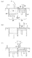
粉末材料として金属粉末を用い、それによって得られる三次元形状造形物を金型として使用する場合の粉末焼結積層法を例にとる。図10に示すように、まず、スキージング・ブレード23を動かして造形プレート21上に所定厚みの粉末層22を形成する(図10(a)参照)。次いで、粉末層22の所定箇所に光ビームLを照射して粉末層22から固化層24を形成する(図10(b)参照)。引き続いて、得られた固化層の上に新たな粉末層を形成して再度光ビームを照射して新たな固化層を形成する。このようにして粉末層形成と固化層形成とを交互に繰り返し実施すると固化層24が積層することになり(図10(c)参照)、最終的には積層化した固化層24から成る三次元形状造形物を得ることができる。最下層として形成される固化層24は造形プレート21と結合した状態になるので、三次元形状造形物と造形プレート21とは一体化物を成すことになり、その一体化物を金型として使用できる。
A powder sintering and laminating method in the case where a metal powder is used as a powder material and a three-dimensional shaped object obtained thereby is used as a mold will be described as an example. As shown in FIG. 10, first, a
上記の粉末焼結積層法では、光ビームが照射される粉末層の照射箇所が焼結現象または溶融固化現象などを経ることによって固化層24となる。かかる固化層24の形成に際しては粉末材料間の空隙が減じられること等に起因して、図11(a)に示すような収縮応力が生じ得る。その結果、三次元形状造形物100とその土台の造形プレート21との一体化物には反り変形が生じ易くなる(図11(b)参照)。つまり、三次元形状造形物100について所望形状が得られない虞がある。
In the powder sintering lamination method described above, the irradiated portion of the powder layer irradiated with the light beam becomes the
本発明は、かかる事情に鑑みて為されたものである。すなわち、本発明の目的は、反り変形が減じられた三次元形状造形物の製造方法を提供することである。 The present invention has been made in view of such circumstances. That is, an object of the present invention is to provide a method of manufacturing a three-dimensionally shaped object with reduced warpage deformation.
上記目的を達成するために、本発明では、
(i)粉末層の所定箇所に光ビームを照射して当該所定箇所の粉末を焼結又は溶融固化させて固化層を形成する工程、および
(ii)得られた固化層の上に新たな粉末層を形成し、当該新たな粉末層の所定箇所に光ビームを照射して更なる固化層を形成する工程
により粉末層形成および固化層形成を交互に繰り返して行う三次元形状造形物の製造方法であって、
三次元形状造形物の土台として、造形プレートおよびダミー固化層を有して成るプレート積層体を用い、
造形プレートの一方の主面上にダミー固化層を形成する一方、造形プレートの他方の主面上で三次元形状造形物を製造する、三次元形状造形物の製造方法が提供される。
In order to achieve the above object, in the present invention,
(I) irradiating a predetermined portion of the powder layer with a light beam to sinter or melt-solidify the powder at the predetermined portion to form a solidified layer; and (ii) new powder on the obtained solidified layer. Forming a layer and irradiating a predetermined portion of the new powder layer with a light beam to form a further solidified layer, a method of manufacturing a three-dimensionally shaped object in which powder layer formation and solidified layer formation are alternately repeated. And
As a base of the three-dimensional shaped object, using a plate laminate having a modeling plate and a dummy solidified layer,
A method of manufacturing a three-dimensionally shaped object is provided, wherein a dummy solidified layer is formed on one main surface of a modeling plate, and a three-dimensionally shaped object is manufactured on the other main surface of the modeling plate.
本発明の製造方法では、反り変形が減じられた三次元形状造形物を得ることができる。 According to the manufacturing method of the present invention, it is possible to obtain a three-dimensionally shaped object with reduced warpage deformation.
以下では、図面を参照して本発明の一実施形態をより詳細に説明する。図面における各種要素の形態および寸法は、あくまでも例示にすぎず、実際の形態および寸法を反映するものではない。 Hereinafter, an embodiment of the present invention will be described in more detail with reference to the drawings. The shapes and dimensions of various elements in the drawings are merely examples, and do not reflect actual shapes and dimensions.
本明細書において「粉末層」とは、例えば「金属粉末から成る金属粉末層」または「樹脂粉末から成る樹脂粉末層」を意味している。また「粉末層の所定箇所」とは、製造される三次元形状造形物の領域を実質的に指している。従って、かかる所定箇所に存在する粉末に対して光ビームを照射することによって、その粉末が焼結又は溶融固化して三次元形状造形物を構成することになる。更に「固化層」とは、粉末層が金属粉末層である場合には「焼結層」を意味し、粉末層が樹脂粉末層である場合には「硬化層」を意味している。 In the present specification, the “powder layer” means, for example, a “metal powder layer made of metal powder” or a “resin powder layer made of resin powder”. The “predetermined portion of the powder layer” substantially indicates a region of the three-dimensionally shaped object to be manufactured. Therefore, by irradiating the light beam on the powder present at such a predetermined location, the powder is sintered or melt-solidified to form a three-dimensionally shaped object. Further, the “solidified layer” means a “sintered layer” when the powder layer is a metal powder layer and a “hardened layer” when the powder layer is a resin powder layer.
また、本明細書で直接的または間接的に説明される“上下”の方向は、例えば三次元形状造形物の製造時におけるプレート積層体と三次元形状造形物との位置関係に基づいており、プレート積層体を基準にして三次元形状造形物が製造される側を「上方向」とし、その反対側を「下方向」とする。 The “up and down” directions described directly or indirectly in the present specification are based on, for example, the positional relationship between the plate laminate and the three-dimensionally shaped object at the time of manufacturing the three-dimensionally shaped object, The side on which the three-dimensionally shaped object is manufactured is referred to as “upward” with respect to the plate laminate, and the opposite side is referred to as “downward”.
[粉末焼結積層法]
まず、本発明の製造方法の前提となる粉末焼結積層法について説明する。特に粉末焼結積層法において三次元形状造形物の切削処理を付加的に行う光造形複合加工を例として挙げる。図10は、光造形複合加工のプロセス態様を模式的に示しており、図12および図13は、粉末焼結積層法と切削処理とを実施できる光造形複合加工機の主たる構成および動作のフローチャートをそれぞれ示している。
[Powder sintering lamination method]
First, a powder sintering lamination method, which is a premise of the production method of the present invention, will be described. In particular, a stereolithography combined machining in which a cutting process of a three-dimensionally shaped object is additionally performed in the powder sintering lamination method will be described as an example. FIG. 10 schematically shows a process mode of the optical molding combined machining. FIGS. 12 and 13 are flow charts of a main configuration and operation of the optical molding combined machining apparatus capable of performing the powder sintering lamination method and the cutting process. Are respectively shown.
光造形複合加工機1は、図12に示すように、粉末層形成手段2、光ビーム照射手段3および切削手段4を備えている。
As shown in FIG. 12, the
粉末層形成手段2は、金属粉末または樹脂粉末などの粉末を所定厚みで敷くことによって粉末層を形成するための手段である。光ビーム照射手段3は、粉末層の所定箇所に光ビームLを照射するための手段である。切削手段4は、積層化した固化層の側面、すなわち、三次元形状造形物の表面を削るための手段である。
The powder
粉末層形成手段2は、図10に示すように、粉末テーブル25、スキージング・ブレード23、支持テーブル20および造形プレート21を主に有して成る。粉末テーブル25は、外周が壁26で囲まれた粉末材料タンク28内にて上下に昇降できるテーブルである。スキージング・ブレード23は、粉末テーブル25上の粉末19を支持テーブル20上へと供して粉末層22を得るべく水平方向に移動できるブレードである。支持テーブル20は、外周が壁27で囲まれた造形タンク29内にて上下に昇降できるテーブルである。そして、造形プレート21は、支持テーブル20上に配され、三次元形状造形物の土台となるプレートである。
As shown in FIG. 10, the powder
光ビーム照射手段3は、図12に示すように、光ビーム発振器30およびガルバノミラー31を主に有して成る。光ビーム発振器30は、光ビームLを発する機器である。ガルバノミラー31は、発せられた光ビームLを粉末層22にスキャニングする手段、すなわち、光ビームLの走査手段である。
The light beam irradiating means 3 mainly includes a
切削手段4は、図12に示すように、エンドミル40および駆動機構41を主に有して成る。エンドミル40は、積層化した固化層の側面、すなわち、三次元形状造形物の表面を削るための切削工具である。駆動機構41は、エンドミル40を所望の切削すべき箇所へと移動させる手段である。
The cutting means 4 mainly has an
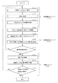
光造形複合加工機1の動作について詳述する。光造形複合加工機1の動作は、図13のフローチャートに示すように、粉末層形成ステップ(S1)、固化層形成ステップ(S2)および切削ステップ(S3)から構成されている。粉末層形成ステップ(S1)は、粉末層22を形成するためのステップである。かかる粉末層形成ステップ(S1)では、まず支持テーブル20をΔt下げ(S11)、造形プレート21の上面と造形タンク29の上端面とのレベル差がΔtとなるようにする。次いで、粉末テーブル25をΔt上げた後、図10(a)に示すようにスキージング・ブレード23を粉末材料タンク28から造形タンク29に向かって水平方向に移動させる。これによって、粉末テーブル25に配されていた粉末19を造形プレート21上へと移送させることができ(S12)、粉末層22の形成が行われる(S13)。粉末層22を形成するための粉末材料としては、例えば「平均粒径5μm〜100μm程度の金属粉末」および「平均粒径30μm〜100μm程度のナイロン、ポリプロピレンまたはABS等の樹脂粉末」を挙げることができる。粉末層22が形成されたら、固化層形成ステップ(S2)へと移行する。固化層形成ステップ(S2)は、光ビーム照射によって固化層24を形成するステップである。かかる固化層形成ステップ(S2)においては、光ビーム発振器30から光ビームLを発し(S21)、ガルバノミラー31によって粉末層22上の所定箇所へと光ビームLをスキャニングする(S22)。これによって、粉末層22の所定箇所の粉末を焼結又は溶融固化させ、図10(b)に示すように固化層24を形成する(S23)。光ビームLとしては、炭酸ガスレーザ、Nd:YAGレーザ、ファイバレーザまたは紫外線などを用いてよい。
The operation of the
粉末層形成ステップ(S1)および固化層形成ステップ(S2)は、交互に繰り返して実施する。これにより、図10(c)に示すように複数の固化層24が積層化する。
The powder layer forming step (S1) and the solidified layer forming step (S2) are performed alternately and repeatedly. As a result, a plurality of solidified
積層化した固化層24が所定厚みに達すると(S24)、切削ステップ(S3)へと移行する。切削ステップ(S3)は、積層化した固化層24の側面、すなわち、三次元形状造形物の表面を削るためのステップである。エンドミル40(図10(c)および図12参照)を駆動させることによって切削ステップが開始される(S31)。例えば、エンドミル40が3mmの有効刃長さを有する場合、三次元形状造形物の高さ方向に沿って3mmの切削処理を行うことができるので、Δtが0.05mmであれば60層分の固化層24が積層した時点でエンドミル40を駆動させる。具体的には駆動機構41によってエンドミル40を移動させながら、積層化した固化層24の側面に対して切削処理を施すことになる(S32)。このような切削ステップ(S3)の最終では、所望の三次元形状造形物が得られているか否かを判断する(S33)。所望の三次元形状造形物が依然得られていない場合では、粉末層形成ステップ(S1)へと戻る。以降、粉末層形成ステップ(S1)〜切削ステップ(S3)を繰り返し実施して更なる固化層の積層化および切削処理を実施することによって、最終的に所望の三次元形状造形物が得られる。
When the laminated solidified
[本発明の製造方法]
本発明は、上述した粉末焼結積層法で製造する三次元形状造形物の土台に特徴を有している。
[Production method of the present invention]
The present invention is characterized by the base of a three-dimensionally shaped object manufactured by the powder sintering and laminating method described above.
具体的には、本発明では、少なくとも2層から成るプレート積層体50を三次元形状造形物の土台として用いる(図1参照)。プレート積層体50を用いることによって、最終的に、反り変形が減じられた三次元形状造形物を得ることができる。
Specifically, in the present invention, a
プレート積層体50は、図1に示されるように、造形プレート21’およびダミー固化層24’を有して成る。ここで、本明細書における「プレート積層体」といった用語は、三次元形状造形物を製造するための土台であって、特に積層構造を有するプレート状の土台のことを意味している。
As shown in FIG. 1, the
図示する態様から分かるように、プレート積層体50の積層構造は、造形プレート21’とダミー固化層24’とが互いに積層した形態を有している。造形プレート21’は、粉末焼結積層法で常套的に用いられる造形プレート21(図10(a)参照)に相当するところ、特に三次元形状造形物の製造前にて残留応力を内部に有し得るプレートである(“残留応力”については後述する)。一方、ダミー固化層24’は、造形プレート21’の主面に設けられる固化層であって、特に三次元形状造形物(固化層24)が接する主面とは反対側の主面に設けられる固化層である(図1参照)。換言すれば、ダミー固化層24’は、造形プレート21’を介して三次元形状造形物と離隔する層に相当する。
As can be seen from the illustrated embodiment, the laminated structure of the
このような事項から分かるように、本明細書で用いる「ダミー固化層」の“ダミー”といった用語は、土台上で製造される三次元形状造形物を構成する固化層とは“異なる”固化層のことを実質的に意味している。 As can be understood from such matters, the term “dummy” in the “dummy solidified layer” used in the present specification is a “solidified layer that is“ different ”from the solidified layer constituting the three-dimensionally shaped object manufactured on the base. That means substantially.
本発明の製造方法において、プレート積層体50は、反り変形を一旦経た積層体である。特に、ダミー固化層24’の形成によって得られる反り変形した積層体50’に平面加工処理を施してプレート積層体50を得ることが好ましい(図2参照)。このようなプレート積層体50は、三次元形状造形物の製造に先立って調製しておくことが好ましい。
In the manufacturing method of the present invention, the
より具体的には、まず、造形プレート21’上にダミー固化層24’を形成して積層体50’を得る(図2(a)および図2(b)参照)。図11(a)および図11(b)を参照して説明した現象の如く、ダミー固化層24’の形成に際しては積層体50’に反り変形が生じる。次いで、かかる反り変形した積層体50’を好ましくは平面加工処理に付す(図2(b)および図2(c)参照)。特に“土台”として好適な形状が得られるように平面加工処理を行うことが好ましい。平面加工処理は、反り変形した積層体50’の主面を実質的に平らな面とする処理である。以上の如くの“反り変形”および“平面加工処理”が行われることによって、本発明で用いるのに好適なプレート積層体50を得ることができる。
More specifically, first, a dummy solidified layer 24 'is formed on the modeling plate 21' to obtain a laminate 50 '(see FIGS. 2A and 2B). As described with reference to FIGS. 11A and 11B, when forming the dummy solidified layer 24 ', the laminate 50' is warped. Next, the warped and deformed laminated body 50 'is preferably subjected to a plane processing (see FIGS. 2B and 2C). In particular, it is preferable to perform a plane processing so as to obtain a shape suitable as a “base”. The planar processing is a process of making the main surface of the warped and deformed laminate 50 'substantially flat. By performing the “warping deformation” and the “planar processing” as described above, a
なお、平面加工処理では、プレート積層体50が三次元形状造形物の製造の“土台”としてより好適な形状を有するように、反り変形した積層体50’の対向する両主面を切削加工に付すことが好ましい。より具体的には、図2(b)および図2(c)に示すように、反り変形に起因した湾曲部分を除去して平坦な面が両主面で得られるように積層体50’に切削加工処理を施すことが好ましい。これにより、プレート積層体50の両主面が互いに実質的に平行な関係を有することになり、“土台”としてプレート積層体50を用いた際、実質的に水平となった面上で三次元形状造形物を好適に製造できる。
In the planar processing, both opposing main surfaces of the
プレート積層体50は、反り変形を一旦経ているので、内部に応力が残存した状態となっている。つまり、プレート積層体50はその内部に残留応力を有し得る。特に、プレート積層体50を構成する造形プレート21’においては、図3に示すように、外側に向いた応力14が残存し得る。従って、三次元形状造形物の製造に際して、三次元形状造形物に生じ得る応力に抗するようにプレート積層体50の残留応力を利用すれば、三次元形状造形物の反り変形を減じることができる。
Since the
図4に示されるように、「プレート積層体50の残留応力14の向き」と「三次元形状造形物100に生じ得る応力15の向き」とが互いに逆になるようにプレート積層体50を設置することが好ましい。三次元形状造形物100の製造に際して、それらの応力(14,15)が相殺されるように相互作用するからである。つまり、図4に示すようにプレート積層体50を設ければ、三次元形状造形物100に生じ得る応力15がプレート積層体50の残留応力14によって緩和されることになり、結果として、反り変形が減じられた三次元形状造形物100を好適に得ることができる。
As shown in FIG. 4, the
「プレート積層体50の残留応力14の向き」と「三次元形状造形物100に生じ得る応力15の向き」とが互いに逆となるようにするには、プレート積層体50の両主面のうちダミー固化層24’が形成されていない側の主面が上側となるようにプレート積層体50を設置することが好ましい。つまり、ダミー固化層24’が形成される造形プレート21’の主面を“表側主面”とみなすと、造形プレート21’の“裏側主面”が上側となるようにプレート積層体50を設置することが好ましい。
In order for the “direction of the
例えば上述した光造形複合加工機1(図10および図12〜13参照)で三次元形状造形物を製造する場合を例にとると、プレート積層体50を図5に示すように支持テーブル20上に設置することが好ましい。かかる場合、支持テーブル20に設置されたプレート積層体50の上側の露出面は上記“裏側主面”に相当する。つまり、支持テーブル20に固定化したプレート積層体50を用いて粉末層形成および固化層形成を行うに際して、ダミー固化層24’が造形プレート21’と支持テーブル20との間に位置付けられるようにプレート積層体50を支持テーブル20に固定化することが好ましい。図5に示すように支持テーブル20に固定化されたプレート積層体50では残留応力14の向きは“外側”となっているところ、そのプレート積層体50上に製造される三次元形状造形物に生じ得る応力の向きは“内側”となる。従って、結果的には、それらの応力が互いに相殺されるようになり、反り変形が減じられた三次元形状造形物を得ることができる。
For example, in a case where a three-dimensionally shaped object is manufactured by the above-described stereolithography machine 1 (see FIGS. 10 and 12 to 13), the
以下においては、本発明の一実施形態に係る製造方法を経時的に説明する。 Hereinafter, a manufacturing method according to an embodiment of the present invention will be described with time.
(1)造形プレートの準備
まず、図6(a)に示すように、造形プレート21’を準備する。ここで準備する造形プレート21’は、粉末焼結積層法で常套的に用いられる造形プレート21(図10(a)参照)であってよい。例えば粉末として金属粉末を用いることによって固化層として焼結層(鉄系材料から成る焼結層)を形成する場合、造形プレート21’の材質は、スチール、超硬合金、高速度工具鋼、合金工具鋼、ステンレス鋼および機械構造用炭素鋼から成る群から選択される少なくとも1種類の材質であってよい。また、造形プレート21’は、あくまでも“プレート”ゆえ、典型的には全体として扁平状となっていることが好ましい。造形プレート21’の具体的な形状は、製造される三次元形状造形物に対して“土台”を供するものであれば、いずれの形状でもよい。それゆえ、造形プレート21’の形状は、直方体形状に特に限定されず、円板形状または多角柱形状などであってもよい。造形プレート21’の主面サイズは、一般的には三次元形状造形物の底面サイズよりも大きいことが求められ、例えば、三次元形状造形物の底面サイズの110〜200%程度であってよい。更に、造形プレート21’の厚み(すなわち、三次元形状造形物の製造時における積層方向の造形プレート寸法)は、例えば10〜70mm程度であってよい。
(1) Preparation of modeling plate First, as shown in FIG. 6A, a modeling plate 21 'is prepared. The shaping
(2)反り変形の付加
準備した造形プレート21’は、ダミー固化層24’の形成を通じて反り変形に付す(図6(a)および図6(b)参照)。具体的には、まず、造形プレート21’上に粉末層を形成し、その粉末層に対して光ビームを照射してダミー固化層24’を形成する。
(2) Addition of Warp Deformation The prepared modeling plate 21 'is subjected to warp deformation through formation of a dummy solidified layer 24' (see FIGS. 6A and 6B). Specifically, first, a powder layer is formed on the modeling plate 21 ', and the powder layer is irradiated with a light beam to form a dummy solidified layer 24'.
ダミー固化層24’の形成に用いられる粉末材料は、後刻の三次元形状造形物の製造に用いる粉末材料と同じであってよい。つまり、例えば平均粒径5μm〜100μm程度の金属粉末を用いてよい。そのような粉末材料を用いることによってダミー固化層24’のための粉末層が形成される。粉末層に対しては光ビームが全体的に照射され、粉末材料の焼結又は溶融固化を経てダミー固化層24’が形成されることになる。ダミー固化層24’の厚みは例えば0.1mm〜10mm程度であってよい。なお、図6(b)に示されるように、ダミー固化層24’は、造形プレート21’の主面全体に及ぶように広範に形成してよい。 The powder material used to form the dummy solidified layer 24 'may be the same as the powder material used to manufacture the three-dimensionally shaped object later. That is, for example, a metal powder having an average particle size of about 5 μm to 100 μm may be used. By using such a powder material, a powder layer for the dummy solidified layer 24 'is formed. The powder layer is entirely irradiated with the light beam, and the sintering or melting and solidification of the powder material forms the dummy solidified layer 24 '. The thickness of the dummy solidified layer 24 'may be, for example, about 0.1 mm to 10 mm. As shown in FIG. 6B, the dummy solidified layer 24 'may be formed over a wide area so as to cover the entire main surface of the modeling plate 21'.
ここで、ダミー固化層24’の形成時においては、粉末材料間の空隙が減じられることに起因して収縮応力が生じ、ダミー固化層24’とそれが接合する造形プレート21’とが反り変形する。つまり、ダミー固化層24’と造形プレート21’とから成る積層体50’に反り変形が発生する。かかる積層体50’では、“反り”に起因して造形プレート21’にて外側に向かって働く応力14が残存し得る(図6(b)参照)。特に、ダミー固化層24’が形成された造形プレート21’の主面を“表側主面”とみなした場合、造形プレート21’の“裏側主面”の近傍に外側に向かって働く応力14が残存され得る。
Here, when the dummy solidified layer 24 'is formed, contraction stress is generated due to the reduction in the gap between the powder materials, and the dummy solidified layer 24' and the shaping plate 21 'to which it is bonded are warped. I do. That is, the laminate 50 'including the dummy solidified layer 24' and the modeling plate 21 'is warped. In such a laminate 50 ',
(3)平面加工処理
反り変形した積層体50’に対しては、平面加工処理を施す(図6(b)および図6(c)参照)。より具体的には、反り変形に起因した湾曲部分を除去して平坦な面が得られるように積層体50’を切削加工処理に付す。図示されるように、特に積層体50’の対向する両主面に対して切削加工処理を施すことが好ましい。これにより、当該両主面が互いに実質的に平行となり、三次元形状造形物の土台としてより好適なプレート積層体50が得られることになる。
(3) Plane Processing The warped and deformed laminate 50 'is subjected to a plane processing (see FIGS. 6B and 6C). More specifically, the laminate 50 'is subjected to a cutting process so that a curved surface caused by the warpage deformation is removed to obtain a flat surface. As shown in the figure, it is particularly preferable to perform a cutting process on both opposing main surfaces of the laminate 50 ′. As a result, the two main surfaces become substantially parallel to each other, and a
かかる平面加工処理を施すために切削加工手段を用いてよい。切削加工手段は、表面切削を施せるものであればいずれのものであってよく、例えば、汎用の数値制御(NC:Numerical Control)工作機械またはそれに準ずるものであってよい。特に、切削工具(エンドミル)を自動交換可能なマシニングセンタ(MC)であることが好ましい。エンドミルは、例えば超硬素材の二枚刃ボールエンドミルが主に用いられる。必要に応じて、スクエアエンドミル、ラジアスエンドミルなどを用いてもよい。なお、切削加工手段を用いて切削加工を施した後、積層体50’の両主面の平面度をより上げるために平面研削盤等を用いて平面研削加工を付加的に行ってもよい。 A cutting means may be used to perform such planar processing. The cutting means may be any as long as it can perform surface cutting. For example, it may be a general-purpose numerical control (NC) machine tool or a similar one. In particular, a machining center (MC) capable of automatically changing a cutting tool (end mill) is preferable. As the end mill, for example, a two-blade ball end mill made of a carbide material is mainly used. If necessary, a square end mill, a radius end mill, or the like may be used. After the cutting using the cutting means, the surface grinding may be additionally performed using a surface grinder or the like in order to further increase the flatness of both main surfaces of the laminate 50 '.
(4)プレート積層体の上下反転
上記(1)〜(3)を経ることで得られたプレート積層体50は“反転”に付す。つまり、反り変形後に平面加工処理を施して得られたプレート積層体50は上下ひっくり返される(図6(c)および図6(d)参照)。より具体的には、ダミー固化層24’が相対的に上側に位置付けられ、造形プレート21’が相対的に下側に位置付けられたプレート積層体50を上下ひっくり返す。ダミー固化層24’が形成された造形プレート21’の主面を“表側主面”とみなすと、造形プレート21’の“裏側主面”が上側となるようにプレート積層体50を反転させることになる。
(4) Inversion of
図6(d)に示されるように、“上下反転”によって、ダミー固化層24’が造形プレート21’と支持テーブル20との間に位置付けられるようにプレート積層体50を支持テーブル20に固定化することが好ましい。これにより支持テーブル20に固定化されたプレート積層体50の残留応力14の向きが“外側”となる一方、プレート積層体50上で製造される三次元形状造形物100に生じ得る応力15の向きは“内側”となる(図6(e)参照)。よって、三次元形状造形物100が製造される際にはその“内側”の応力15を打ち消すようにプレート積層体50の残留応力14が好適に作用できるようになる。
As shown in FIG. 6D, the
(5)三次元形状造形物の製造
プレート積層体50の固定化後、そのプレート積層体50を土台として三次元形状造形物100の製造を行う。図6(c)および図6(e)に示す態様から分かるように、プレート積層体50における造形プレート21’の“裏側主面”上で三次元形状造形物100を製造することになる。
(5) Manufacture of three-dimensionally shaped object After the
プレート積層体50上で製造される三次元形状造形物100に生じ得る応力15の向きは“内側”である。これに対して、プレート積層体50では、“反り変形”に起因して残留応力14の向きが“外側”となっている。つまり、三次元形状造形物100の製造時の応力15とプレート積層体50の残留応力14とは互いに逆方向となる。これにより、三次元形状造形物100の製造時の応力15が、プレート積層体50の残留応力14によって緩和され、三次元形状造形物100の反りが減じられることになる。
The direction of the
本願発明者らは、三次元形状造形物100の製造時に生じる応力15は、特に製造初期で相対的に大きく発生することを見出している(図7参照)。より具体的には、図7から分かるように、三次元形状造形物100の底面に大きな応力が生じ得る。これは、三次元形状造形物100とその土台との界面近傍に特に大きな応力が生じることを意味している。
The inventors of the present application have found that the
この点、本発明の製造方法では、土台としてプレート積層体50が用いられるので、製造初期に三次元形状造形物100に生じる応力に対して効果的に影響を与えることができる。より具体的にいえば、三次元形状造形物に生じる応力は、三次元形状造形物の底面で特に大きく発生し得るものの、かかる底面にはプレート積層体50が設けられているので、プレート積層体50の残留応力14で三次元形状造形物の応力15を効果的に減じることができる(図4参照)。
In this regard, in the manufacturing method of the present invention, since the
上記においては本発明の理解のために典型的な実施形態を説明したが、本発明の製造方法としては、種々の具体的な実施形態が考えられる。 Although a typical embodiment has been described above for understanding the present invention, various specific embodiments can be considered as a manufacturing method of the present invention.
(ブラスト加工の態様)
本発明の製造方法は、三次元形状造形物で生じ得る応力に抗するためにプレート積層体の残留応力を利用している。しかしながら、プレート積層体によってはその残留応力が三次元形状造形物に生じ得る応力よりも小さい場合も考えられる。
(Blasting mode)
The manufacturing method of the present invention utilizes the residual stress of the plate laminate in order to withstand the stress that can occur in a three-dimensionally shaped object. However, depending on the plate laminate, the residual stress may be smaller than the stress that can be generated in the three-dimensionally shaped object.
かかる場合、プレート積層体に対してブラスト加工を施すことが好ましい。具体的には、平面加工処理を施した後で得られるプレート積層体50の造形プレート21’の“裏側主面”に対してブラスト加工を付加的に施すことが好ましい(図8参照)。
In such a case, it is preferable to perform blast processing on the plate laminate. Specifically, it is preferable to additionally perform blast processing on the “back main surface” of the shaping
ブラスト加工を施すと、プレート積層体50において外側に向く応力14が強まる作用が供され得る。つまり、プレート積層体50において、三次元形状造形物の応力に抗することになる応力14が増すことになる。これは、ブラスト加工によってプレート積層体50の残留応力14を適宜調整できることを意味しており、それゆえ三次元形状造形物の反り低減がより効率的に行える。
When blasting is performed, an effect of increasing the
なお、ブラスト加工を施すと、プレート積層体の表面粗さが増すことになる。表面粗さの増加は、プレート積層体とその上に製造される三次元形状造形物との接合面積の増加につながる。従って、ブラスト加工を実施した場合、プレート積層体と三次元形状造形物との間の接合力が向上し得、プレート積層体と三次元形状造形物との一体化物の構造強度が増す効果も奏され得る。 When blasting is performed, the surface roughness of the plate laminate increases. The increase in the surface roughness leads to an increase in the bonding area between the plate laminate and the three-dimensionally shaped object manufactured thereon. Therefore, when blasting is performed, the bonding strength between the plate laminate and the three-dimensionally shaped object can be improved, and the structural strength of the integrated body of the plate laminate and the three-dimensionally shaped object can be increased. Can be done.
(ダミー固化層の輪郭サイズ変更の態様)
プレート積層体の調製に際して、ダミー固化層は造形プレートの主面の一部にのみ形成してよい。例えば、図9(a)に示すようにダミー固化層24’の輪郭形状が後刻に製造する三次元形状造形物100の底面の輪郭形状と略同一となるようにダミー固化層24’の形成を行う。かかる態様では、プレート積層体50に残留応力を生じさせつつも、ダミー固化層24’の形成のための時間を最小限に抑えることができる。つまり、ダミー固化層24’に要する光ビームの使用を減じることができ、より効率的な三次元形状造形物100の製造が実現され得る。
(Mode of changing the contour size of the dummy solidified layer)
In preparing the plate laminate, the dummy solidified layer may be formed only on a part of the main surface of the modeling plate. For example, as shown in FIG. 9A, the formation of the dummy solidified layer 24 'is performed so that the outline shape of the dummy solidified layer 24' becomes substantially the same as the outline shape of the bottom surface of the three-dimensional molded
なお、図9(a)に示す態様ではプレート積層体50に必要な残留応力が足りない場合、ダミー固化層24’の輪郭形状を後刻で製造する三次元形状造形物100の底面の輪郭形状よりも大きくしてよい(図9(b)参照)。ダミー固化層24’のサイズが大きくなれば、その分だけプレート積層体50の残留応力14を大きくできるからである。あくまでも例示にすぎないが、ダミー固化層24’の輪郭形状が後刻で製造する三次元形状造形物100の底面の輪郭形状よりも0.5〜10mm程度大きくなるようにダミー固化層24’を形成してよい。より具体的には、プレート積層体50において図9(b)に示す“L”に相当寸法が0.5〜10mm程度となるようにダミー固化層24’を形成してよい。
In the embodiment shown in FIG. 9A, when the residual stress required for the
以上、本発明の一実施形態について説明してきたが、本発明の適用範囲のうちの典型例を例示したに過ぎない。従って、本発明はこれに限定されず、種々の改変がなされ得ることを当業者は容易に理解されよう。 Although the embodiment of the present invention has been described above, it merely illustrates a typical example of the application range of the present invention. Therefore, those skilled in the art will readily understand that the present invention is not limited to this and various modifications can be made.
50 プレート積層体
21’ 造形プレート
24’ ダミー固化層
100 三次元形状造形物
20 支持テーブル
Claims (3)
(ii)得られた固化層の上に新たな粉末層を形成し、該新たな粉末層の所定箇所に光ビームを照射して更なる固化層を形成する工程
により粉末層形成および固化層形成を交互に繰り返して行う三次元形状造形物の製造方法であって、
前記三次元形状造形物の土台として、造形プレートおよびダミー固化層を有して成るプレート積層体を用い、
前記プレート積層体においては、前記造形プレートの一方の主面上に前記ダミー固化層を形成する一方、前記造形プレートの他方の主面上で前記三次元形状造形物を製造し、
前記ダミー固化層の形成によって得られる反り変形した積層体に平面加工処理を施して前記プレート積層体を得、
支持テーブルに固定化した前記プレート積層体を用いて前記粉末層形成および前記固化層形成を行い、
前記ダミー固化層が前記造形プレートと前記支持テーブルとの間に位置付けられるように前記プレート積層体を該支持テーブルに前記固定化する、三次元形状造形物の製造方法。 (I) irradiating a predetermined portion of the powder layer with a light beam to sinter or melt-solidify the powder at the predetermined portion to form a solidified layer; and (ii) new powder on the obtained solidified layer. Forming a layer and irradiating a predetermined portion of the new powder layer with a light beam to form a further solidified layer, wherein the powder layer formation and the solidified layer formation are alternately repeated to produce a three-dimensionally shaped object manufacturing method. And
As a base of the three-dimensional shaped object, using a plate laminate having a modeling plate and a dummy solidified layer,
In the plate laminate, the dummy solidified layer is formed on one main surface of the modeling plate, and the three-dimensional shaped object is manufactured on the other main surface of the modeling plate .
The plate laminate is obtained by subjecting the warped laminate obtained by the formation of the dummy solidified layer to planar processing .
Performing the powder layer formation and the solidified layer formation using the plate laminate fixed to a support table,
A method for manufacturing a three-dimensionally shaped object , wherein the plate laminate is fixed to the support table such that the dummy solidified layer is positioned between the modeling plate and the support table .
Priority Applications (6)
| Application Number | Priority Date | Filing Date | Title |
|---|---|---|---|
| JP2016045893A JP6643631B2 (en) | 2016-03-09 | 2016-03-09 | Manufacturing method of three-dimensional shaped object |
| PCT/JP2017/009190 WO2017154965A1 (en) | 2016-03-09 | 2017-03-08 | Three-dimensional molded object production method |
| EP17763305.4A EP3427870B1 (en) | 2016-03-09 | 2017-03-08 | Three-dimensional molded object production method |
| KR1020187025409A KR102145781B1 (en) | 2016-03-09 | 2017-03-08 | Manufacturing method of 3D shape sculpture |
| CN201780015568.2A CN108778575A (en) | 2016-03-09 | 2017-03-08 | The manufacturing method of three dimensional structure |
| US16/083,362 US10821663B2 (en) | 2016-03-09 | 2017-03-08 | Method for manufacturing three-dimensional shaped object |
Applications Claiming Priority (1)
| Application Number | Priority Date | Filing Date | Title |
|---|---|---|---|
| JP2016045893A JP6643631B2 (en) | 2016-03-09 | 2016-03-09 | Manufacturing method of three-dimensional shaped object |
Publications (3)
| Publication Number | Publication Date |
|---|---|
| JP2017160485A JP2017160485A (en) | 2017-09-14 |
| JP2017160485A5 JP2017160485A5 (en) | 2019-02-14 |
| JP6643631B2 true JP6643631B2 (en) | 2020-02-12 |
Family
ID=59789556
Family Applications (1)
| Application Number | Title | Priority Date | Filing Date |
|---|---|---|---|
| JP2016045893A Active JP6643631B2 (en) | 2016-03-09 | 2016-03-09 | Manufacturing method of three-dimensional shaped object |
Country Status (6)
| Country | Link |
|---|---|
| US (1) | US10821663B2 (en) |
| EP (1) | EP3427870B1 (en) |
| JP (1) | JP6643631B2 (en) |
| KR (1) | KR102145781B1 (en) |
| CN (1) | CN108778575A (en) |
| WO (1) | WO2017154965A1 (en) |
Families Citing this family (7)
| Publication number | Priority date | Publication date | Assignee | Title |
|---|---|---|---|---|
| JP7087430B2 (en) * | 2018-02-14 | 2022-06-21 | セイコーエプソン株式会社 | Manufacturing method of 3D model and 3D modeling device |
| JP6676688B2 (en) * | 2018-04-06 | 2020-04-08 | 株式会社ソディック | Manufacturing method of three-dimensional objects |
| US10780498B2 (en) * | 2018-08-22 | 2020-09-22 | General Electric Company | Porous tools and methods of making the same |
| GB2582567A (en) * | 2019-03-25 | 2020-09-30 | Airbus Operations Ltd | Fixture for additive manufacturing and heat treatment |
| WO2021000794A1 (en) * | 2019-06-29 | 2021-01-07 | 浙江大学 | 3d printing method for complex curved hollow structure, and printer |
| JP7008669B2 (en) * | 2019-09-09 | 2022-01-25 | 日本電子株式会社 | 3D laminated modeling device and 3D laminated modeling method |
| CN115213427A (en) * | 2022-07-19 | 2022-10-21 | 季华实验室 | Additive manufacturing method and product |
Family Cites Families (11)
| Publication number | Priority date | Publication date | Assignee | Title |
|---|---|---|---|---|
| DE3750931T3 (en) | 1986-10-17 | 1999-12-02 | Univ Texas | METHOD AND DEVICE FOR PRODUCING MOLDED BODIES BY PARTIAL INTERSTERING. |
| US4863538A (en) | 1986-10-17 | 1989-09-05 | Board Of Regents, The University Of Texas System | Method and apparatus for producing parts by selective sintering |
| US8070474B2 (en) * | 2007-05-30 | 2011-12-06 | Panasonic Electric Works Co., Ltd. | Lamination shaping apparatus |
| JP5061062B2 (en) * | 2008-08-08 | 2012-10-31 | パナソニック株式会社 | Manufacturing method of three-dimensional shaped object |
| GB0819935D0 (en) | 2008-10-30 | 2008-12-10 | Mtt Technologies Ltd | Additive manufacturing apparatus and method |
| CN102762323B (en) | 2010-02-17 | 2016-05-25 | 松下知识产权经营株式会社 | The manufacture method of three dimensional structure and three dimensional structure |
| JP5535121B2 (en) * | 2011-04-19 | 2014-07-02 | パナソニック株式会社 | Manufacturing method of three-dimensional shaped object |
| JP5895172B2 (en) * | 2012-02-09 | 2016-03-30 | パナソニックIpマネジメント株式会社 | Manufacturing method of three-dimensional shaped object |
| GB2500412A (en) | 2012-03-21 | 2013-09-25 | Eads Uk Ltd | Build Plate for an additive manufacturing process |
| WO2016017155A1 (en) | 2014-07-30 | 2016-02-04 | パナソニックIpマネジメント株式会社 | Method for producing three-dimensionally shaped molded article, and three-dimensionally shaped molded article |
| GB201806369D0 (en) * | 2018-04-19 | 2018-06-06 | Rolls Royce Plc | Stress relieve for additive layer manufacturing |
-
2016
- 2016-03-09 JP JP2016045893A patent/JP6643631B2/en active Active
-
2017
- 2017-03-08 WO PCT/JP2017/009190 patent/WO2017154965A1/en active Application Filing
- 2017-03-08 EP EP17763305.4A patent/EP3427870B1/en active Active
- 2017-03-08 KR KR1020187025409A patent/KR102145781B1/en active IP Right Grant
- 2017-03-08 CN CN201780015568.2A patent/CN108778575A/en active Pending
- 2017-03-08 US US16/083,362 patent/US10821663B2/en active Active
Also Published As
| Publication number | Publication date |
|---|---|
| CN108778575A (en) | 2018-11-09 |
| US20190091923A1 (en) | 2019-03-28 |
| US10821663B2 (en) | 2020-11-03 |
| EP3427870A4 (en) | 2019-01-16 |
| JP2017160485A (en) | 2017-09-14 |
| WO2017154965A1 (en) | 2017-09-14 |
| EP3427870B1 (en) | 2020-01-01 |
| KR20180111912A (en) | 2018-10-11 |
| EP3427870A1 (en) | 2019-01-16 |
| KR102145781B1 (en) | 2020-08-19 |
Similar Documents
| Publication | Publication Date | Title |
|---|---|---|
| JP6643631B2 (en) | Manufacturing method of three-dimensional shaped object | |
| JP5519766B2 (en) | Manufacturing method of three-dimensional shaped object and three-dimensional shaped object | |
| TWI596001B (en) | Method for producing three-dimensional shaped object | |
| JP5119123B2 (en) | Manufacturing method of three-dimensional shaped object | |
| JP5539347B2 (en) | Manufacturing method of three-dimensional shaped object and three-dimensional shaped object obtained therefrom | |
| WO2015133138A1 (en) | Method for producing three-dimensionally shaped object | |
| JP5535121B2 (en) | Manufacturing method of three-dimensional shaped object | |
| JP5186306B2 (en) | Manufacturing method of three-dimensional shaped object | |
| WO2012160811A1 (en) | Method for producing three-dimensional shape structure | |
| CN108602261B (en) | Method for manufacturing three-dimensional shaped object | |
| CN107848212B (en) | Method for manufacturing three-dimensional shaped object | |
| JP2010132961A (en) | Lamination forming device and lamination forming method | |
| JP6628024B2 (en) | Method for manufacturing three-dimensionally shaped object and three-dimensionally shaped object | |
| JP6621072B2 (en) | Manufacturing method of three-dimensional shaped object | |
| JP2002066844A (en) | Method of manufacturing discharge machining electrode using metal powder sintering type laminated molding | |
| JP6643643B2 (en) | Manufacturing method of three-dimensional shaped object | |
| JP6817561B2 (en) | Manufacturing method of 3D shaped object | |
| JP6726858B2 (en) | Method for manufacturing three-dimensional shaped object | |
| JP6688997B2 (en) | Method for manufacturing three-dimensional shaped object | |
| JP4131230B2 (en) | Mold as stereolithography | |
| JP6643644B2 (en) | Manufacturing method of three-dimensional shaped object | |
| JP2023183596A (en) | Metal laminate shaping method | |
| JP2007077443A (en) | Method for manufacturing three-dimensional structure |
Legal Events
| Date | Code | Title | Description |
|---|---|---|---|
| A521 | Request for written amendment filed |
Free format text: JAPANESE INTERMEDIATE CODE: A523 Effective date: 20181226 |
|
| A621 | Written request for application examination |
Free format text: JAPANESE INTERMEDIATE CODE: A621 Effective date: 20181226 |
|
| A131 | Notification of reasons for refusal |
Free format text: JAPANESE INTERMEDIATE CODE: A131 Effective date: 20190903 |
|
| A521 | Request for written amendment filed |
Free format text: JAPANESE INTERMEDIATE CODE: A523 Effective date: 20191101 |
|
| TRDD | Decision of grant or rejection written | ||
| A01 | Written decision to grant a patent or to grant a registration (utility model) |
Free format text: JAPANESE INTERMEDIATE CODE: A01 Effective date: 20191126 |
|
| A61 | First payment of annual fees (during grant procedure) |
Free format text: JAPANESE INTERMEDIATE CODE: A61 Effective date: 20191210 |
|
| R151 | Written notification of patent or utility model registration |
Ref document number: 6643631 Country of ref document: JP Free format text: JAPANESE INTERMEDIATE CODE: R151 |