WO2017154764A1 - 送風機 - Google Patents
送風機 Download PDFInfo
- Publication number
- WO2017154764A1 WO2017154764A1 PCT/JP2017/008440 JP2017008440W WO2017154764A1 WO 2017154764 A1 WO2017154764 A1 WO 2017154764A1 JP 2017008440 W JP2017008440 W JP 2017008440W WO 2017154764 A1 WO2017154764 A1 WO 2017154764A1
- Authority
- WO
- WIPO (PCT)
- Prior art keywords
- stator
- boss
- rotating shaft
- hole
- blower
- Prior art date
Links
Images


Classifications
-
- F—MECHANICAL ENGINEERING; LIGHTING; HEATING; WEAPONS; BLASTING
- F04—POSITIVE - DISPLACEMENT MACHINES FOR LIQUIDS; PUMPS FOR LIQUIDS OR ELASTIC FLUIDS
- F04D—NON-POSITIVE-DISPLACEMENT PUMPS
- F04D29/00—Details, component parts, or accessories
- F04D29/26—Rotors specially for elastic fluids
- F04D29/263—Rotors specially for elastic fluids mounting fan or blower rotors on shafts
-
- F—MECHANICAL ENGINEERING; LIGHTING; HEATING; WEAPONS; BLASTING
- F04—POSITIVE - DISPLACEMENT MACHINES FOR LIQUIDS; PUMPS FOR LIQUIDS OR ELASTIC FLUIDS
- F04D—NON-POSITIVE-DISPLACEMENT PUMPS
- F04D29/00—Details, component parts, or accessories
- F04D29/02—Selection of particular materials
- F04D29/023—Selection of particular materials especially adapted for elastic fluid pumps
-
- F—MECHANICAL ENGINEERING; LIGHTING; HEATING; WEAPONS; BLASTING
- F05—INDEXING SCHEMES RELATING TO ENGINES OR PUMPS IN VARIOUS SUBCLASSES OF CLASSES F01-F04
- F05D—INDEXING SCHEME FOR ASPECTS RELATING TO NON-POSITIVE-DISPLACEMENT MACHINES OR ENGINES, GAS-TURBINES OR JET-PROPULSION PLANTS
- F05D2300/00—Materials; Properties thereof
- F05D2300/40—Organic materials
- F05D2300/44—Resins
Definitions
- the present invention relates to a blower provided with multiblade blades, and more particularly to a fixing structure for a blower in which a resin fan is attached to a rotating shaft of a motor.
- Patent Document 1 Japanese Patent Application Laid-Open No. 2004-3449
- Patent Document 2 Japanese Patent Application Laid-Open No. 2011-163244
- This type of vehicle air conditioner blower is required to be compact and have a large air volume for in-vehicle use. For this reason, a fan having a short distance from the rotation shaft to the blades is rotated at a higher speed than a household blower (fan). As is well known, when the rotational speed is high, noise is generated due to the vibration of the fan or structural imbalance, and thus high balance is required.
- Patent Document 1 also discloses means for fixing a fan to a rotary shaft having a circular cross section. That is, a rotary shaft (shaft 21) having a circular cross section is inserted into a boss portion of the fan (10), and then press-fitted into a through hole of a resin stator (cap 30) that is harder than the fan, and further the boss portion and the stator. Are fitted along the axial direction of the rotating shaft. Since the hard stator is fixed to the rotating shaft, it is possible to prevent the fan fitted to the stator from idling with respect to the rotating shaft.
- the portion that fits into the fan is formed only on one side in the axial direction. Therefore, in order to properly fit the fan inserted earlier, a fixed direction (constant Orientation)) and needs to be mounted on the rotating shaft.
- the present invention has been made in view of the above-described circumstances, and relates to a blower having a structure in which a fan is fixed to a rotary shaft having a circular cross section.
- a stator is attached to the rotary shaft, and the stator prevents the multi-blade blade from idling.
- An object of the present invention is to obtain a blower fixing structure that increases the degree of freedom in the mounting direction of the stator.
- a motor M having a rotary shaft 1 having a circular cross section; A resin stator 10 mounted on the rotating shaft; A resin fan 60 having a boss 30 attached to the stator,
- the stator 10 is A stator through hole 14 into which the rotary shaft 1 is press-fitted, A stator first engagement portion that engages with a boss engagement portion 35 provided on the boss 30 when the rotary shaft 1 is in a first mounting posture in which the rotation shaft 1 is press-fitted from one side of the stator through-hole 14.
- stator second engagement portion 16 that engages with the boss engagement portion 35 when the rotary shaft 1 is in a second mounting posture in which the rotation shaft 1 is press-fitted from the other side of the stator through-hole 14; It is the air blower 100 characterized by this.
- the stator through-hole 14 is provided with a small-diameter portion 14 a between the one side and the other side, the diameter of the through-hole being smaller than the outer diameter of the rotary shaft 1.
- the blower 100 according to claim 1.
- the invention of claim 3 is characterized in that the stator through-hole 14 is provided with tapered portions 14b, 14c that gradually decrease in diameter from the one side and the other side toward the small diameter portion 14a.
- the blower 100 according to 2.
- the stator 10 is configured such that the one side and the other side are congruent with respect to a virtual cross section L2 in the middle between the end portion on the one side and the end portion on the other side. It is the air blower 100 in any one of Claim 1 thru
- the rotating shaft 1 is press-fitted from one side of the stator through-hole 14 so that the stator 10 is fixed to the rotating shaft (first mounting posture), and the boss 30 is fixed to the stator 10. Since the engaging portion 35 of the boss 30 is engaged with and engaged with the stator first engaging portion 15 of the stator 10, the fan 60 is fixed so as not to idle. can do.
- the rotating shaft 1 When the rotating shaft 1 is press-fitted from the other side of the stator through-hole 14 and the stator 10 is fixed to the rotating shaft (second mounting posture), and the boss 30 is attached to the stator 10, the stator The engaging portion 35 of the boss 30 is engaged with and engaged with the tenth stator second engaging portion 16, and thus, in the second mounting posture, as in the first mounting posture, the rotation shaft 1 can be fixed so that the fan 60 does not idle.
- the stator through hole 14 is provided with the small diameter portion 14 a between the one side and the other side, the diameter of the through hole being smaller than the outer diameter of the rotating shaft 1.
- the stator 10 can be firmly attached to the rotating shaft 1 in both the first and second mounting postures of the stator 10.
- stator through-hole 14 is provided with the tapered portions 14b and 14c whose diameter gradually decreases from the one side and the other side toward the small diameter portion 14a, the rotation of the stator 10 is achieved. Mounting on the shaft 1 can be made relatively easily.
- the one side and the other side are congruent with respect to the virtual cross section L2 in the middle between the one end and the other end. Therefore, the mounting of the rotating shaft 1 to the stator through hole 14 can be performed from either side without using the stator as a so-called top and bottom, and the degree of freedom in the mounting direction of the stator. Can be increased, which is convenient in assembling.
- a blower fixing structure that increases the degree of freedom in the mounting direction of the stator can be obtained.
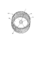
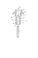
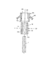
- or FIG. 14 has shown each component (component) of the air blower concerning 1st embodiment of this invention.
- the blower 100 according to the present embodiment is made of a resin having a motor M having a rotary shaft 1 having a circular cross section, a resin stator 10 attached to the rotary shaft 1, and a boss 30 attached to the stator 10.
- the fan 60 includes a cone 50 extending from the boss 30 and a resin fan 60 having a large number of blades extending from the outer peripheral edge of the cone 50.
- the stator 10 is formed of a resin having a high mechanical strength
- the boss 30 is formed of a resin having a mechanical strength lower than that of the stator 10. ing.
- the stator 10 and the boss 30 may be formed of a resin having the same mechanical strength.
- the stator 10 and the fan 60 are formed by a known molding method such as injection molding.
- the resin material for example, polypropylene or ABS resin is used.
- the stator 10 is a cylindrical member and is attached to the rotary shaft 1 as described above.
- a fan 60 is attached to the stator 10 via a boss 30, and the rotation of the rotary shaft 1 is transmitted to the fan 60 via the stator 10. Therefore, the stator 10 is firmly fixed to the rotary shaft 1 so as not to slip with respect to the rotary shaft 1 or move in the axial direction.
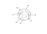
- the stator 10 includes a stator first end surface 11 close to the tip of the rotating shaft 1, a stator second end surface 12 far from the tip of the rotating shaft, and a stator first.
- a stator outer peripheral surface 13 formed between one end surface 11 and the stator second end surface 12, a stator through hole 14 into which the rotary shaft 1 is press-fitted, and a concave or convex formed in the stator outer peripheral surface 13.
- a stator first engagement portion 15 having a shape and a concave or convex stator second engagement portion 16 formed on the stator outer peripheral surface 15 and formed at a location different from the stator first engagement portion. And comprising.
- stator first engagement portion 15 and the stator second engagement portion 16 have a concave shape. Further, the first stator engaging portion 15 and the second stator engaging portion 16 are arranged radially and equiangularly around the virtual axis L1 of the rotating shaft 1. In addition, these arrangement
- positioning aspects are stator 2nd engagement in the middle of each stator 1st engaging part 15 (intermediate of the some stator 1st engaging part 15 in the circumferential direction of the stator outer peripheral surface 13). It is provided so that the part 16 may be located.
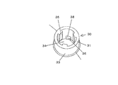
- the boss 30 is a cylindrical member, is a part of the fan 60, is formed of resin, and is attached to the stator 10.
- the boss 30 of the present embodiment includes a boss first end surface 31 close to the tip of the rotating shaft 1, a boss second end surface 32 far from the tip of the rotating shaft 1, and a boss first
- a boss outer peripheral surface 33 formed between the end surface 31 and the boss second end surface 32, a boss through hole 34 into which the stator 10 is inserted, and an inner peripheral surface of the boss through hole 34, the first stator engagement.
- a boss first engaging portion 35 that engages with the joint portion 15 and a boss second engaging portion 36 that engages with the stator second engaging portion 16.
- the boss first end face 31 is located on the upper side of the drawing
- the boss second end face 32 is located on the lower side of the drawing.
- the boss first engagement portion 35 and the boss second engagement portion 36 are convex shapes corresponding to the concave shapes of the stator first engagement portion 15 and the stator second engagement portion 16.
- the boss first engagement portion 35 and the boss second engagement portion 36 are arranged around the virtual axis of the rotary shaft 1 corresponding to the stator first engagement portion 15 and the stator second engagement portion 16. And are arranged radially and equiangularly. As in the case of the stator 10, these arrangement modes are arranged in the middle of each boss first engagement portion 35 (in the middle of the plurality of boss first engagement portions 35 in the circumferential direction of the boss through-hole 34).
- the boss second engaging portion 36 is provided so as to be positioned.
- stator first engaging portion 15 extends from the stator first end surface 11 along the axial direction of the rotary shaft 1 and extends as shown in detail in FIGS. 10 and 11.
- the stator first restricting portion 17 is provided at the end portion.
- the stator second engaging portion 16 extends from the stator second end surface 12 along the axial direction of the rotating shaft 1 and is formed by providing a stator second restricting portion 18 at the extended end. .
- the boss first engaging portion 35 is formed by extending from the boss first end surface 31 along the axial direction of the rotating shaft 1 and providing the boss first restricting portion 37 at the extended end portion.
- the boss second engaging portion 36 extends from a position away from the boss first end surface 31 along the axial direction of the rotary shaft 1, and a boss second restricting portion 38 at the end on the boss first end surface 31 side. Is formed.
- the boss second engaging portion 36 may be formed by extending from the boss second end surface 32 along the axial direction of the rotary shaft 1 and providing the boss second restricting portion 38 at the extended end. . It is appropriately selected depending on the convenience of the mold.
- first stator restricting portion 17 and the first boss restricting portion 37 form a first restricting mechanism 70 that restricts the movement range of the boss 30 along the axial direction of the rotating shaft 1. (See FIG. 13).
- stator second restricting portion 18 and the boss second restricting portion 38 form a second restricting mechanism 80 that restricts the movement range of the boss 30 along the axial direction of the rotating shaft 1 (FIG. 13). reference).
- the cone 50 extends from the outer peripheral surface 33 of the boss corresponding to the first stator engaging portion 15 or the second stator engaging portion 16 in the axial direction of the rotary shaft 1.
- the rotary shaft 1 of the motor is press-fitted and attached to the stator through hole 14 of the stator 10 (the rotary shaft 1 is press-fitted and attached to the stator 10).
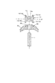
- the boss 30 of the fan 60 is attached from the front end side of the rotating shaft 1, that is, moved from the stator first end surface 11 side, and the engaging portions of the boss 30 are engaged with the engaging portions of the stator 10. .
- the boss first engagement portion 35 of the boss 30 is changed to the stator first engagement portion 15, and the boss second engagement portion 36 is changed.
- the stator outer peripheral surface 13 is aligned with the second stator engaging portion 16 so as to correspond to each other in the axial direction, and first, for example, the boss second engaging portion 36 formed in a known claw shape is compressed. Move it while sliding.
- the boss first engaging portion 35 is engaged with the stator first engaging portion 15 and the boss second engaging portion 36 is engaged with and engaged with the stator second engaging portion 16.
- the boss first engaging portion 35 is engaged with the stator first engaging portion 15 and the boss second engaging portion 36 is engaged with the stator second engaging portion 16 by engaging the concave and convex portions, respectively. Therefore, the fan 60 can be fixed to the rotating shaft 1 so as not to idle.
- the rotational driving force transmitted from the rotating shaft 1 to the stator 10 is transmitted from the stator 10 to the boss 30 toward the radially outer side of the rotating shaft, and then transmitted to the cone 50. Furthermore, since the cone 50 extends from the boss outer peripheral surface 33 corresponding to the stator engaging portion to the radially outer side of the rotating shaft 1, the rotational driving force to the cone is also transmitted toward the radially outer side of the rotating shaft 1. Is done. Thus, in the blower of this embodiment, transmission of the driving force to the rotating shaft 1, the stator 10, the boss 30, and the cone 50 is transmitted toward the radially outer side of the rotating shaft 1, that is, the rotating shaft. Since it is not made in the direction, it is possible to eliminate the cause of shaking or imbalance during rotation of the impeller.
- first restriction mechanism 70 formed by the stator first restriction portion 17 and the boss first restriction portion 37 of the present embodiment described above has a movement range of the boss 30 in a direction away from the tip of the rotating shaft 1.
- the second restricting mechanism 80 formed by the stator second restricting portion 18 and the boss second restricting portion 38 restricts the movement range of the boss 30 in the direction approaching the tip of the rotating shaft 1.
- the first restricting mechanism 70 and the second restricting mechanism 80 are provided in this manner, the axial movement of the boss 30 with respect to the rotating shaft 1 can be prevented, and the axial movement of the fan 60 can be avoided. can do.
- first stator engaging portion 15 and the second stator engaging portion 16 are concave, and the first boss engaging portion 35 and the second boss engaging portion 36 are convex.
- first stator engaging portion 15 and the second stator engaging portion 16 are formed in a convex shape, and the first boss engaging portion 35 and the second boss engaging portion. 36 may be formed in a concave shape.
- stator first restricting portion 17 and the stator second restricting portion 18 have the same position from the stator first end surface 11 along the axial direction of the rotating shaft 1. Furthermore, it is desirable that the boss first restricting portion 37 and the boss second restricting portion 38 have the same position from the boss first end surface 31 along the axial direction of the rotation shaft 1. It becomes easy to provide the parting line at the same position, the design of the mold is facilitated, and the productivity of the stator 10 and the fan 60 can be improved.
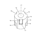
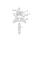
- the stator 10 is configured such that the one side and the other side are congruent with respect to the virtual cross section L2 between the stator first end surface 11 and the stator second end surface 12. It is formed to become.
- the stator 10 is mounted with the first end face 11 of the stator facing the rotating shaft 1 (first mounting posture, especially FIGS. 12 and 13). The boss 30 is attached to this.
- stator 10 is turned upside down, that is, as shown in FIG. 14, the stator second end face 12 is mounted on the rotating shaft 1 (second mounting posture), The above-described attachment of the boss 30 to the stator 10 can be similarly performed without any trouble.
- stator 10 when the stator 10 is formed so as to be congruent with the virtual cross section L2 in the middle, the stator 10 can be mounted from either end face when the stator 10 is mounted on the rotary shaft 1. Since it is good, the convenience in an assembly can be improved.
- the stator 10 is formed so as to be congruent with the virtual cross section L2 in the middle between the stator first end surface 11 and the stator second end surface 12. Therefore, it is preferable that the first stator engaging portion 15 and the second stator engaging portion 16 have the same axial length, but the present invention is not limited to this.
- the axial lengths of the first engaging portion 15 and the second stator engaging portion 16 are allowed to be different so as not to hinder the rotation of the fan.
- FIG. 15 to 19 show the stator 10 and the boss 30 of the blower according to the second embodiment of the present invention.
- the thing of this embodiment uses the cap-shaped stator 10 as shown, for example in the said patent document 1.
- the thing of 2nd embodiment of this invention is mounted
- the stator first engagement portion 15 that engages with the boss engagement portion 35 provided on the boss 30 and the rotation shaft 1 from the other side of the stator through hole 14 in the first mounting posture.
- the stator second engaging portion 16 that engages with the boss engaging portion 35 in the second mounting posture to be mounted.
- the stator 10 is formed so as to be congruent with the virtual cross section L2 in the middle of the stator 10 in the axial direction. Furthermore, it may be formed so as to be plane-symmetric with respect to the virtual cross section L2. And in the example of illustration (FIG. 16 and FIG. 17) in this 2nd embodiment, the stator 10 is mounted
- the reference numerals 15 and 16 are shown in parentheses so that the stator first engaging portion 16 is arranged on the lower side with respect to the rotary shaft 1, that is, the stator 10 It is possible to engage the boss 30 by mounting it upside down.
- FIG. 18 shows another example of the second embodiment.
- the diameter of the through hole between the one side and the other side of the stator through hole 14 is the rotation.
- a small diameter portion 14 a smaller than the outer diameter of the shaft 1 is provided.
- stator 10 can be firmly attached to the rotating shaft 1 in both the first and second mounting postures of the stator 10.
- FIG. 19 shows another example of the second embodiment.
- the diameter gradually decreases in the stator through hole 14 from the one side and the other side toward the small diameter portion 14a. Tapered portions 14b and 14c are provided.
- the stator 10 is formed so as to be congruent with respect to the virtual cross section L2 in the middle between the one end and the other end.
- the stator 10 can be mounted on the rotary shaft 1 from either side, so that the stator is not used upside down, and the mounting direction of the stator.
- the degree of freedom can be increased, which is convenient in assembling.
- the fixing structure of the blower that increases the degree of freedom in the mounting direction of the stator. Can be obtained.
- the blower according to the present invention can be manufactured industrially, and can be suitably used particularly for a vehicle air conditioner.
Landscapes
- Engineering & Computer Science (AREA)
- Mechanical Engineering (AREA)
- General Engineering & Computer Science (AREA)
- Structures Of Non-Positive Displacement Pumps (AREA)
Abstract
Description
断面円形の回転軸1を有するモータMと、
前記回転軸に装着された樹脂製の固定子10と、
前記固定子に取付けられたボス30を有する樹脂製のファン60と、を備え、
前記固定子10は、
前記回転軸1が圧入される固定子貫通孔14と、
前記回転軸1が前記固定子貫通孔14の一方側から圧入される第1の装着姿勢のときに、前記ボス30に設けられたボス係合部35と係合する固定子第1係合部15と、
前記回転軸1が前記固定子貫通孔14の他方側から圧入される第2の装着姿勢のときに、前記ボス係合部35と係合する固定子第2係合部16と、を備えたことを特徴とする送風機100である。
1 回転軸
10 固定子
11 固定子第1端面
12 固定子第2端面
13 固定子外周面
14 固定子貫通孔
14a 小径部
14b テーパ部
14c テーパ部
15 固定子第1係合部
16 固定子第2係合部
17 固定子第1規制部
18 固定子第2規制部
30 ボス
31 ボス第1端面
32 ボス第2端面
33 ボス外周面
34 ボス貫通孔
35 ボス第1係合部
36 ボス第2係合部
37 ボス第1規制部
38 ボス第2規制部
50 コーン
60 ファン
70 第1規制機構
80 第2規制機構
100 送風機
L1 回転軸の仮想軸線
L2 仮想断面
Claims (4)
- 断面円形の回転軸1を有するモータMと、
前記回転軸に装着された樹脂製の固定子10と、
前記固定子に取付けられたボス30を有する樹脂製のファン60と、を備え、
前記固定子10は、
前記回転軸1が圧入される固定子貫通孔14と、
前記回転軸1が前記固定子貫通孔14の一方側から圧入される第1の装着姿勢のときに、前記ボス30に設けられたボス係合部35と係合する固定子第1係合部15と、
前記回転軸1が前記固定子貫通孔14の他方側から圧入される第2の装着姿勢のときに、前記ボス係合部35と係合する固定子第2係合部16と、を備えたことを特徴とする送風機100。 - 前記固定子貫通孔14に、前記一方側と前記他方側との間に当該貫通孔の径が前記回転軸1の外径よりも小さい小径部14aを備えていることを特徴とする請求項1記載の送風機100。
- 前記固定子貫通孔14に、前記一方側および前記他方側から前記小径部14aに向けて漸次径が小さくなるテーパ部14b,14cを設けたことを特徴とする請求項2記載の送風機100。
- 前記固定子10は、前記一方側の端部と前記他方側の端部との中間における仮想断面L2に対して、前記一方側と前記他方側とが合同となるように形成されている請求項1ないし請求項3のいずれか記載の送風機100。
Priority Applications (3)
| Application Number | Priority Date | Filing Date | Title |
|---|---|---|---|
| CN201780014853.2A CN108713102B (zh) | 2016-03-08 | 2017-03-03 | 送风机 |
| EP17763104.1A EP3428455A4 (en) | 2016-03-08 | 2017-03-03 | BLOWER |
| JP2018504442A JPWO2017154764A1 (ja) | 2016-03-08 | 2017-03-03 | 送風機 |
Applications Claiming Priority (2)
| Application Number | Priority Date | Filing Date | Title |
|---|---|---|---|
| JP2016-044111 | 2016-03-08 | ||
| JP2016044111 | 2016-03-08 |
Publications (1)
| Publication Number | Publication Date |
|---|---|
| WO2017154764A1 true WO2017154764A1 (ja) | 2017-09-14 |
Family
ID=59790597
Family Applications (1)
| Application Number | Title | Priority Date | Filing Date |
|---|---|---|---|
| PCT/JP2017/008440 WO2017154764A1 (ja) | 2016-03-08 | 2017-03-03 | 送風機 |
Country Status (4)
| Country | Link |
|---|---|
| EP (1) | EP3428455A4 (ja) |
| JP (1) | JPWO2017154764A1 (ja) |
| CN (1) | CN108713102B (ja) |
| WO (1) | WO2017154764A1 (ja) |
Families Citing this family (1)
| Publication number | Priority date | Publication date | Assignee | Title |
|---|---|---|---|---|
| CN112797022B (zh) * | 2020-12-21 | 2022-06-28 | 珠海格力电器股份有限公司 | 一种风叶组件及具有它的电机 |
Citations (5)
| Publication number | Priority date | Publication date | Assignee | Title |
|---|---|---|---|---|
| JPH03102094U (ja) * | 1990-02-01 | 1991-10-24 | ||
| JP2003314493A (ja) * | 2002-04-22 | 2003-11-06 | Denso Corp | 送風機および送風機の製造方法 |
| JP2004308608A (ja) * | 2003-04-09 | 2004-11-04 | Denso Corp | 送風機 |
| DE102011086379A1 (de) * | 2011-11-15 | 2013-05-16 | Robert Bosch Gmbh | Gebläsemodul für ein Kraftfahrzeug, Klimatisierungseinrichtung |
| EP2960523A1 (fr) * | 2014-06-23 | 2015-12-30 | Compagnie Industrielle D'Applications Thermiques | Bague de fixation pour roue de turbine d'unité de traitement d'air et unité de traitement d'air comprenant un tel élément de fixation |
Family Cites Families (9)
| Publication number | Priority date | Publication date | Assignee | Title |
|---|---|---|---|---|
| US2702087A (en) * | 1951-03-26 | 1955-02-15 | Schwitzer Cummins Company | Fan assembly |
| DE7913075U1 (de) * | 1979-05-05 | 1979-08-16 | Papst-Motoren Kg, 7742 St Georgen | Luefter mit rohrlaeufermotor |
| US6200098B1 (en) * | 1999-07-01 | 2001-03-13 | Behr America, Inc. | Speed limited fan |
| CN2563337Y (zh) * | 2002-08-01 | 2003-07-30 | 林三原 | 散热风扇的组配结构 |
| CN2628760Y (zh) * | 2003-06-02 | 2004-07-28 | 奇鋐科技股份有限公司 | 风扇扇轮的轮毂与轴心结合装置 |
| JP5396868B2 (ja) * | 2009-01-16 | 2014-01-22 | パナソニック株式会社 | 送風機 |
| CN202732499U (zh) * | 2012-06-20 | 2013-02-13 | 重庆润通动力有限公司 | 发电机冷却风扇的安装结构 |
| JP6366389B2 (ja) * | 2014-07-03 | 2018-08-01 | 株式会社日本クライメイトシステムズ | ファンの取付構造 |
| JP6340281B2 (ja) * | 2014-08-04 | 2018-06-06 | 株式会社日本クライメイトシステムズ | ファンの取付構造 |
-
2017
- 2017-03-03 CN CN201780014853.2A patent/CN108713102B/zh not_active Expired - Fee Related
- 2017-03-03 WO PCT/JP2017/008440 patent/WO2017154764A1/ja active Application Filing
- 2017-03-03 EP EP17763104.1A patent/EP3428455A4/en not_active Withdrawn
- 2017-03-03 JP JP2018504442A patent/JPWO2017154764A1/ja active Pending
Patent Citations (5)
| Publication number | Priority date | Publication date | Assignee | Title |
|---|---|---|---|---|
| JPH03102094U (ja) * | 1990-02-01 | 1991-10-24 | ||
| JP2003314493A (ja) * | 2002-04-22 | 2003-11-06 | Denso Corp | 送風機および送風機の製造方法 |
| JP2004308608A (ja) * | 2003-04-09 | 2004-11-04 | Denso Corp | 送風機 |
| DE102011086379A1 (de) * | 2011-11-15 | 2013-05-16 | Robert Bosch Gmbh | Gebläsemodul für ein Kraftfahrzeug, Klimatisierungseinrichtung |
| EP2960523A1 (fr) * | 2014-06-23 | 2015-12-30 | Compagnie Industrielle D'Applications Thermiques | Bague de fixation pour roue de turbine d'unité de traitement d'air et unité de traitement d'air comprenant un tel élément de fixation |
Non-Patent Citations (1)
| Title |
|---|
| See also references of EP3428455A4 * |
Also Published As
| Publication number | Publication date |
|---|---|
| JPWO2017154764A1 (ja) | 2019-01-10 |
| EP3428455A4 (en) | 2019-11-13 |
| CN108713102A (zh) | 2018-10-26 |
| EP3428455A1 (en) | 2019-01-16 |
| CN108713102B (zh) | 2019-11-26 |
Similar Documents
| Publication | Publication Date | Title |
|---|---|---|
| US20060276122A1 (en) | Electric fan | |
| JP4081473B2 (ja) | コンプレッサーに対してエンジンの回転トルクを伝達するための装置 | |
| CN107313958B (zh) | 用于风扇的驱动组件及具有的风扇 | |
| US20020176780A1 (en) | Device for fixing a fan-blade assembly onto a motor shaft | |
| JP4389998B2 (ja) | 遠心式多翼ファン | |
| US10808724B2 (en) | Rotor of an electric motor | |
| WO2017154764A1 (ja) | 送風機 | |
| TWI725683B (zh) | 扇輪及具有該扇輪之散熱風扇 | |
| JP4063308B1 (ja) | 送風機の羽根車のボス構造及びそれを備えた送風機の羽根車 | |
| CN105889132B (zh) | 静翼单元以及送风机 | |
| JP2014015851A (ja) | ファン用防振ボス及び回転ファンの製造方法 | |
| KR101528877B1 (ko) | 팬용 허브조립체 | |
| EP2149713B1 (en) | Axial flow fan | |
| WO2017179499A1 (ja) | 送風機 | |
| JP2007278193A (ja) | 送風機 | |
| KR101819127B1 (ko) | 원심팬 | |
| JP2007078096A (ja) | 車両のホイール | |
| JP6687050B2 (ja) | 遠心送風機 | |
| CN210970608U (zh) | 一种带有叶片连杆的出风口装置 | |
| WO2017138493A1 (ja) | 送風機 | |
| CN107084145B (zh) | 用于风扇的驱动组件及具有其的风扇 | |
| JP5724380B2 (ja) | 軸流ファン | |
| JP2016164437A (ja) | ダイナミックダンパ | |
| JP4491909B2 (ja) | 遠心式送風機 | |
| JP2011140977A (ja) | ダイナミックダンパ |
Legal Events
| Date | Code | Title | Description |
|---|---|---|---|
| WWE | Wipo information: entry into national phase |
Ref document number: 2018504442 Country of ref document: JP |
|
| NENP | Non-entry into the national phase |
Ref country code: DE |
|
| WWE | Wipo information: entry into national phase |
Ref document number: 2017763104 Country of ref document: EP |
|
| ENP | Entry into the national phase |
Ref document number: 2017763104 Country of ref document: EP Effective date: 20181008 |
|
| 121 | Ep: the epo has been informed by wipo that ep was designated in this application |
Ref document number: 17763104 Country of ref document: EP Kind code of ref document: A1 |