WO2017154697A1 - 動弁装置及びクロスヘッド式内燃機関 - Google Patents
動弁装置及びクロスヘッド式内燃機関 Download PDFInfo
- Publication number
- WO2017154697A1 WO2017154697A1 PCT/JP2017/008116 JP2017008116W WO2017154697A1 WO 2017154697 A1 WO2017154697 A1 WO 2017154697A1 JP 2017008116 W JP2017008116 W JP 2017008116W WO 2017154697 A1 WO2017154697 A1 WO 2017154697A1
- Authority
- WO
- WIPO (PCT)
- Prior art keywords
- hydraulic oil
- oil supply
- supply path
- casing
- valve
- Prior art date
- Legal status (The legal status is an assumption and is not a legal conclusion. Google has not performed a legal analysis and makes no representation as to the accuracy of the status listed.)
- Ceased
Links
Images




Classifications
-
- F—MECHANICAL ENGINEERING; LIGHTING; HEATING; WEAPONS; BLASTING
- F01—MACHINES OR ENGINES IN GENERAL; ENGINE PLANTS IN GENERAL; STEAM ENGINES
- F01L—CYCLICALLY OPERATING VALVES FOR MACHINES OR ENGINES
- F01L9/00—Valve-gear or valve arrangements actuated non-mechanically
- F01L9/10—Valve-gear or valve arrangements actuated non-mechanically by fluid means, e.g. hydraulic
- F01L9/11—Valve-gear or valve arrangements actuated non-mechanically by fluid means, e.g. hydraulic in which the action of a cam is being transmitted to a valve by a liquid column
-
- F—MECHANICAL ENGINEERING; LIGHTING; HEATING; WEAPONS; BLASTING
- F01—MACHINES OR ENGINES IN GENERAL; ENGINE PLANTS IN GENERAL; STEAM ENGINES
- F01L—CYCLICALLY OPERATING VALVES FOR MACHINES OR ENGINES
- F01L9/00—Valve-gear or valve arrangements actuated non-mechanically
- F01L9/10—Valve-gear or valve arrangements actuated non-mechanically by fluid means, e.g. hydraulic
-
- F—MECHANICAL ENGINEERING; LIGHTING; HEATING; WEAPONS; BLASTING
- F01—MACHINES OR ENGINES IN GENERAL; ENGINE PLANTS IN GENERAL; STEAM ENGINES
- F01M—LUBRICATING OF MACHINES OR ENGINES IN GENERAL; LUBRICATING INTERNAL COMBUSTION ENGINES; CRANKCASE VENTILATING
- F01M9/00—Lubrication means having pertinent characteristics not provided for in, or of interest apart from, groups F01M1/00 - F01M7/00
- F01M9/10—Lubrication of valve gear or auxiliaries
Definitions
- the present invention relates to a valve operating apparatus for driving an exhaust valve in an internal combustion engine such as a diesel engine or a gas engine, and a crosshead internal combustion engine provided with the valve operating apparatus.
- a valve operating device that opens and closes an exhaust valve includes a lower valve operating device and an upper valve operating device.
- the valve operating device supplies the hydraulic oil compressed by the lower valve operating device to the upper valve operating device, and pushes down the exhaust valve against the urging force of the air spring using the transmitted hydraulic oil driving force. Open and close the exhaust valve.
- a sliding cylinder urged downward by a spring is supported in a casing so as to be movable in the vertical direction.
- the sliding cylinder can be supplied by compressing the hydraulic oil by being pushed up by a cam to raise the piston.
- Patent Document 1 As a conventional valve gear, for example, there is one described in Patent Document 1 below.
- the rotating cam needs to supply lubricating oil to the sliding surface between the cam and the roller because the cam portion pushes up the sliding cylinder via the roller.
- part of the hydraulic oil used to drive the exhaust valve by supplying it to the upper valve operating device has been supplied to the cam and roller as lubricating oil. That is, a pipe for supplying hydraulic oil (lubricating oil) from the outside is provided through a camshaft box in which a sliding cylinder and a cam are accommodated, and a pipe for supplying hydraulic oil from the outside is connected to a cylinder in which a piston is accommodated. It was. For this reason, there are problems that a plurality of pipes are required, the structure becomes complicated, and the manufacturing cost increases.
- the present invention solves the above-described problems, and an object thereof is to provide a valve operating apparatus and a crosshead type internal combustion engine that simplify the structure.
- a valve operating apparatus includes an apparatus main body including a lower casing and an upper casing, a sliding cylinder supported movably in the axial direction with respect to the lower casing, and the upper section
- a piston that is movably supported in the axial direction with respect to the casing and moves integrally with the sliding cylinder, a cam that moves the sliding cylinder, and a hydraulic oil that is provided in the upper casing and that is provided to the apparatus main body.
- a hydraulic oil supply unit that supplies the compression chamber, the compression chamber for compressing a part of the hydraulic oil supplied from the hydraulic oil supply unit by movement of the piston to the upper casing, and the compression from the hydraulic oil supply unit.
- the sliding cylinder reciprocates in the axial direction by the rotational force of the cam, and the piston reciprocates integrally with the sliding cylinder. Then, the hydraulic oil supplied to the compression chamber from the hydraulic oil supply unit through the first hydraulic oil supply path is compressed and discharged. Further, the hydraulic oil supplied from the hydraulic oil supply unit through the second hydraulic oil supply path is supplied to the cam, and the cam is lubricated.
- the first hydraulic oil supply path for supplying hydraulic oil from one hydraulic oil supply section to the compression chamber is provided, and the second hydraulic oil supply path for supplying hydraulic oil to the cam is provided, thereby providing the hydraulic oil supply section.
- the piping configuration to the apparatus is simplified, and the processing of the oil passage for the apparatus main body is also simplified. As a result, the structure can be simplified.
- the upper casing is provided at an upper portion of a camshaft box, an opening communicating with the cam is provided on a side surface of the camshaft box, and the hydraulic oil is supplied to the hydraulic oil supply section.
- the hydraulic oil supply pipe for supplying is arranged above the opening.
- the hydraulic oil supply pipe for supplying the hydraulic oil to the hydraulic oil supply section above the opening, the hydraulic oil supply pipe interferes with an operator who performs various operations on the cam from the opening. No, workability can be improved.
- the first hydraulic oil supply path allows the flow of the hydraulic oil from the hydraulic oil supply unit to the compression chamber and allows the operation from the compression chamber to the hydraulic oil supply unit.
- a check valve that prohibits the flow of oil is provided, and a hydraulic oil discharge section that discharges the hydraulic oil compressed in the compression chamber between the compression chamber and the check valve in the first hydraulic oil supply path It is characterized by being connected.
- the hydraulic oil when the hydraulic oil is supplied to the hydraulic oil supply section, it is supplied to the compression chamber through the first hydraulic oil supply path, and the hydraulic oil is compressed in the compression chamber when the piston is raised, and is discharged from the hydraulic oil discharge section.
- the hydraulic oil compressed in the compression chamber does not flow back to the hydraulic oil supply unit, but can be properly discharged from the hydraulic oil discharge unit. it can.
- the opening on the lower casing side in the second hydraulic oil supply path is connected to the hydraulic oil supply path in the lower casing, and the hydraulic oil supply path in the lower casing is
- the upper casing is provided along the axial direction in the lower casing, and has an upper end opened to the upper casing and a lower end opened toward the cam.
- the supply path formed in the apparatus main body can be simplified.
- the sliding cylinder is provided with a key groove along the axial direction on the outer peripheral surface, a key fixed to the lower casing is inserted into the key groove, and a hydraulic oil supply path in the lower casing Comprises a keyway and a communication groove provided in the key.
- the crosshead internal combustion engine of the present invention includes a lower valve operating device to which the valve operating device is applied, and an upper valve operating device that drives an exhaust valve with hydraulic oil from the lower valve operating device. It is characterized by.
- the sliding cylinder reciprocates in the axial direction by the rotational force of the cam, and the piston reciprocates integrally with the sliding cylinder. Then, the hydraulic oil supplied to the compression chamber from the hydraulic oil supply unit through the first hydraulic oil supply path is compressed and discharged. Further, the hydraulic oil supplied from the hydraulic oil supply unit through the second hydraulic oil supply path is supplied to the cam, and the cam is lubricated.
- the first hydraulic oil supply path for supplying hydraulic oil from one hydraulic oil supply section to the compression chamber is provided, and the second hydraulic oil supply path for supplying hydraulic oil to the cam is provided, thereby providing the hydraulic oil supply section.
- the piping configuration to the apparatus is simplified, and the processing of the oil passage for the apparatus main body is also simplified. As a result, the structure can be simplified.
- valve gear and the crosshead internal combustion engine of the present invention the structure can be simplified.
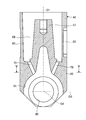
- FIG. 1 is a cross-sectional view showing the lower valve train of the present embodiment.
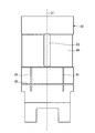
- FIG. 2 is a cross-sectional view showing a sliding cylinder in the lower valve operating apparatus.
- FIG. 3 is a right side view of the sliding tube.
- FIG. 4 is a left side view of the sliding tube.
- 5 is a cross-sectional view taken along the line VV of FIG. 2 showing a horizontal cross section of the sliding cylinder.
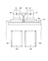
- FIG. 6 is a front view showing the lower valve train.
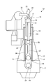
- FIG. 7 is a schematic diagram showing a diesel engine.
- FIG. 8 is a schematic diagram showing the valve gear of the present embodiment.
- valve operating apparatus and a crosshead internal combustion engine according to the present invention will be described in detail with reference to the accompanying drawings.
- this invention is not limited by this embodiment, and when there are two or more embodiments, what comprises combining each embodiment is also included.
- FIG. 7 is a schematic diagram showing a diesel engine.
- the diesel engine 10 is, for example, a two-stroke, one-cycle, uniflow scavenging crosshead internal combustion engine that is used as a main engine for ship propulsion.
- the diesel engine 10 includes a base plate 11 positioned below, a frame 12 provided on the base plate 11, and a cylinder jacket 13 provided on the frame 12.
- the base plate 11, the frame 12, and the cylinder jacket 13 are integrally fastened and fixed by a plurality of tension bolts 14 and nuts 15 extending in the vertical direction.
- the cylinder liner 16 and the cylinder cover 17 define a space portion, and a piston 18 is provided in the space portion so as to be able to reciprocate up and down, whereby a combustion chamber 19 is formed. Further, the cylinder cover 17 is provided with an exhaust valve 20 and can be opened and closed by a valve operating device 21. The exhaust valve 20 opens and closes the combustion chamber 19 and the exhaust pipe 22.
- the cylinder jacket 13, the cylinder liner 16, and the cylinder cover 17 constitute a combustion device.
- fuel for example, low-quality oil, natural gas, or a mixed fuel thereof supplied from a fuel injection pump (not shown) to the combustion chamber 19 and combustion gas (for example, air) compressed by a compressor (not shown) , EGR gas, or a mixed gas thereof) is combusted.
- combustion gas for example, air
- the piston 18 moves up and down by the energy generated by this combustion.
- exhaust gas generated by combustion is pushed out to the exhaust pipe 22, while combustion gas is introduced into the combustion chamber 19 from a scavenging port (not shown).
- the upper end of the piston rod 23 is connected to the lower end of the piston 18.
- the base plate 11 constitutes a crankcase, and a bearing 25 that rotatably supports the crankshaft 24 is provided.
- the crankshaft 24 is rotatably connected to the lower end portion of the connecting rod 27 via a crank 26.
- a pair of guide plates 28 extending in the vertical direction are fixed at a predetermined interval, and a cross head 29 is supported between the pair of guide plates 28 so as to be movable up and down.
- the cross head 29 is connected to the lower end of the piston rod 23 and the upper end of the connecting rod 27.
- the piston 18 to which energy is transmitted from the combustion chamber 19 is pushed down together with the piston rod 23 in the direction of the installation surface of the diesel engine 10 (the direction on the base plate 11 side, that is, downward in the vertical direction). Then, the piston rod 23 pushes down the cross head 29 in the same direction, and rotates the crankshaft 24 via the connecting rod 27 and the crank 26.
- FIG. 8 is a schematic diagram showing the valve gear of the present embodiment.
- the valve gear 21 includes a lower valve gear 31 and an upper valve gear 32 as shown in FIG.
- the valve operating device 21 supplies the hydraulic oil compressed by the lower valve operating device 31 to the upper valve operating device 32, pushes down the exhaust valve 20 using the transmitted driving force of the hydraulic oil, and the exhaust valve 20 in the closed state. Open and close.
- the exhaust valve 20 is composed of a shaft portion 20a and an umbrella portion 20b, and is movably supported by a casing 33 fixed to the cylinder cover 17.
- the upper valve device 32 closes the space between the combustion chamber 19 and the exhaust pipe 22 by the exhaust valve 20 when the urging force of the air spring 34 acts the shaft portion 20a upward.
- the upper valve mechanism 32 includes a cylinder portion 35 that receives hydraulic oil supplied from the lower valve mechanism 31, and a piston 36 that is movably provided in the cylinder portion 35. ing.
- the piston 36 is integrally fixed to the upper end portion of the shaft portion 20a, and moves up and down integrally with the exhaust valve 20.
- a sliding cylinder 42 is supported in a casing (lower casing, apparatus main body) 41 so as to be movable in the vertical direction (axial direction). It is biased and supported downward by the biasing force.
- the casing 41 is provided with a cylinder part (upper casing, apparatus main body) 44 at the upper part, and both are fastened by a plurality of bolts (not shown).
- the sliding cylinder 42 is provided with a roller (roller portion) 45 rotatably at the lower end portion, and a piston 46 is connected to the upper end portion, and the piston 46 moves in the vertical direction (axial direction) within the cylinder portion 44. It is provided freely.
- a cam 47 that contacts the roller 45 is disposed below the sliding cylinder 42.
- the cam 47 rotates in synchronization with the crankshaft 24 (see FIG. 7).
- the cylinder portion 44 of the lower valve operating device 31 and the cylinder portion 35 of the upper valve operating device 32 are connected by a hydraulic oil pipe 48.
- FIG. 1 is a cross-sectional view showing the lower valve train of the present embodiment.
- the casing 41 has a cylindrical shape, and is provided with a sliding portion 51 that opens in the vertical direction (axial direction).
- the sliding tube 42 is fitted to the sliding portion 51 of the casing 41 and is supported so as to be movable along the vertical direction (axial direction).
- the sliding cylinder 42 is rotatably mounted on the lower end portion thereof by a support shaft 52 along a direction orthogonal to the axial direction.
- the sliding cylinder 42 and the roller 45 are integrated in the vertical direction (axial direction). It can move along.
- the sliding cylinder 42 has a key groove 53 extending in the vertical direction (axial direction) on the outer peripheral surface over a predetermined length.
- the casing 41 is formed with a mounting hole 54 along the horizontal direction, the key 55 is fitted into the mounting hole 54 from the outside of the casing 41, and the tip is fitted into the key groove 53 of the sliding cylinder 42. . Therefore, the sliding cylinder 42 cannot be rotated in the circumferential direction with respect to the casing 41 by the key 55. In this case, the length of the key groove 53 is longer than the maximum stroke of the sliding cylinder 42.
- the casing 41 has a cylinder portion 44 integrally fixed to an upper portion thereof.
- the cylinder portion 44 is provided with a sliding portion 56 extending downward along the vertical direction (axial direction).
- the sliding portion 56 is smaller in diameter than the sliding portion 51 but is provided concentrically.
- the sliding cylinder 42 is provided with a projecting portion 57 extending upward at the center thereof, and the piston 46 is integrally connected to the upper end portion of the projecting portion 57 via a connecting member 58.
- the piston 46 is fitted to the sliding portion 56 of the casing 41 so as to be vertically movable, so that a compression chamber 59 is defined above the piston 46. Therefore, when the sliding cylinder 42 rises, the piston 46 rises via the connecting member 58 and the hydraulic oil in the compression chamber 59 can be compressed.
- a first hydraulic oil supply path for supplying hydraulic oil to the compression chamber 59 and a second hydraulic oil supply path for supplying hydraulic oil to the cam 47 as lubricating oil are provided.
- the cylinder portion 44 is provided with a hydraulic oil supply port (hydraulic oil supply portion) 61 on the side, and the hydraulic oil supply port 61 is connected to a chamber 62. Further, the cylinder portion 44 has a hydraulic oil discharge port (hydraulic oil discharge portion) 63 formed at the upper end portion, and the hydraulic oil discharge port 63 and the compression chamber 59 are in a first connection flow path 64 along the vertical direction (axial direction). It is communicated by. Furthermore, the cylinder part 44 is provided so that the second connection flow path 65 extending in the radial direction through the center of the cylinder part 44 intersects the first connection flow path 64.
- the second connection channel 65 has one end communicating with the chamber 62 and the other end communicating with an oil hole 66 penetrating the cylinder portion 44 in the vertical direction (axial direction).
- a check valve 67 is provided between the second connection channel 65 and the chamber 62, and a relief valve 68 is provided between the second connection channel 65 and the oil hole 66.
- the check valve 67 prevents the flow of hydraulic oil from the compression chamber 59 side to the hydraulic oil supply port 61 side, and the relief valve 68 is opened when the pressure in the compression chamber 59 exceeds a predetermined pressure.
- the sliding cylinder 42 is provided with a spring accommodating space 69 around the protrusion 57 and accommodates the compression coil spring 43.
- the compression coil spring 43 has an upper end portion in contact with the lower surface of the cylinder portion 44 and a lower end portion in contact with the sliding cylinder 42. Therefore, the sliding cylinder 42 is biased and supported downward with respect to the casing 41 and the cylinder portion 44 by the biasing force of the compression coil spring 43.
- the oil hole 66 formed in the cylinder portion 44 has a lower end opened to the spring accommodating space 69.
- the slide tube 42 is formed with a drain hole 70 penetrating from the spring accommodating space 69 to the roller 45 side.
- the cylinder portion 44 is formed with a first lubricating oil supply hole (upper supply path) 71 whose upper end portion communicates with the chamber 62 and whose lower end portion extends downward and opens to the casing 41 side.
- the casing 41 communicates with the key groove 53 of the sliding cylinder 42 through a communication groove 55 a formed at the lower end portion of the key 55, and the upper end portion extends upward and opens to the cylinder portion 44 side.
- An oil supply hole (lower supply path) 72 is formed.
- the first lubricating oil supply hole 71 has a lower end communicating with the upper end of the second lubricating oil supply hole 72.
- the sliding cylinder 42 can supply lubricating oil from the keyway 53 to the roller 45 and the cam 47 (see FIG. 8).
- FIG. 2 is a sectional view showing a sliding cylinder in the lower valve operating apparatus
- FIG. 3 is a right side view of the sliding cylinder
- FIG. 4 is a left side view of the sliding cylinder
- FIG. 5 is a horizontal section of the sliding cylinder.
- FIG. 6 is a front view showing the lower valve operating apparatus.
- the sliding cylinder 42 is provided with a lubricating oil reservoir 80, a first lubricating oil supply path 81, and a second lubricating oil supply path 82.
- the sliding cylinder 42 has a cylindrical shape, and a roller accommodating portion 91 that accommodates the roller 45 (see FIG. 1) is formed at the lower end portion, and a support shaft (not shown) of the roller 45 passes therethrough.
- a support hole 92 is formed.
- the center line O1 of the sliding cylinder 42 is provided along the vertical direction (axial direction), and the axial center line O2 of the roller 45 is provided along the direction orthogonal to the paper surface of FIG.
- the center line O1 of the roller and the axis O2 of the roller 45 are substantially orthogonal to each other.
- the axial center line O2 of the roller 45 coincides with the axial center line of the cam 47 and is parallel.
- the sliding cylinder 42 has a key groove 53 that extends in the vertical direction on the outer peripheral surface along the center line O1 of the sliding cylinder 42.
- the lubricating oil reservoir 80 is provided on the outer peripheral surface of the sliding cylinder 42 along the circumferential direction with the length of the key groove 53 (the length of the sliding cylinder 42 in the direction of the center line O1).
- the lubricating oil reservoir 80 is configured as a recess that dents the outer peripheral surface of the sliding cylinder 42 along the circumferential direction of the key groove 53.
- the first lubricating oil supply path 81 is a groove provided on the outer peripheral portion of the sliding cylinder 42 along the center line O1 of the sliding cylinder 42 (four in this embodiment).
- the first lubricating oil supply path 81 has an upper end (one end) in the axial direction communicating with the lubricating oil reservoir 80, and a lower end (the other end) in the axial direction extends to the middle of the lower end of the sliding cylinder 42.
- the four first lubricating oil supply paths 81 are provided at positions shifted outward from the width W of the roller 45 in the direction of the axis O2.
- Each first lubricating oil supply path 81 is provided at a symmetrical position in the radial direction of the sliding cylinder 42 with respect to the axis O2 of the roller 45.
- each first lubricating oil supply path 81 is connected to the axis O2 side from the axis O3. Are formed at positions shifted by a predetermined angle ⁇ .
- the positions of the first lubricating oil supply paths 81 are formed at symmetrical positions in the radial direction of the sliding cylinder 42 with respect to the axis O2 of the roller 45, and the sliding cylinder 42 also with respect to the axis 3. Are formed at symmetrical positions in the radial direction.
- the second lubricating oil supply path 82 is a circumferential groove portion provided in the outer peripheral portion of the sliding cylinder 42 along the circumferential direction.
- Each first lubricating oil supply path 81 has a lower end portion that intersects and communicates with the second lubricating oil supply path 82, and extends further down to a dead end.
- the first hydraulic oil supply path for supplying the hydraulic oil to the compression chamber 59 is configured by the hydraulic oil supply port 61, the chamber 62, the second connection flow path 65, and the first connection flow path 64.
- the second hydraulic oil supply path for supplying hydraulic oil as lubricant to the cam 47 is connected to the hydraulic oil supply path in the casing 41, and the hydraulic oil supply path in the casing 41 extends along the axial direction of the casing 41.
- the upper end portion is provided so as to open toward the casing 41, and the lower end portion is formed to open toward the cam 47.
- the second hydraulic oil supply path includes the hydraulic oil supply port 61, the chamber 62, the first lubricating oil supply hole 71, the second lubricating oil supply hole 72, the key 55, the key groove 53, the lubricating oil reservoir 80, and the first.
- a lubricating oil supply path 81 and a second lubricating oil supply path 82 are included.
- the casing 41 and the cylinder portion 44 are fixed side by side on the upper portion of the camshaft box 101.
- the camshaft box 101 is provided with a maintenance opening 102 on the side surface corresponding to each casing 41 and cylinder portion 44 for maintaining a cam 47 (see FIG. 1), a camshaft (not shown), and the like. It is closed by the open / close lid 103.
- the hydraulic oil supply pipe 104 for supplying hydraulic oil is disposed on the side of the camshaft box 101 and along the horizontal direction in which the casings 41 and the cylinder portions 44 are arranged.
- the hydraulic oil supply pipe 104 is connected to the hydraulic oil supply port 61 of each cylinder part 44 via a supply pipe along the axial direction and each branch pipe 105 that branches the hydraulic oil from this supply pipe to each cylinder part 44. ing.
- the hydraulic oil supply pipe 104 is arranged above each maintenance opening 102 so as not to interfere with maintenance work such as the cam 47 and the cam shaft.
- the casing 41 and the cylinder portion 44, the sliding cylinder 42 movably supported by the casing 41, and the piston 46 connected to the upper end portion of the sliding cylinder 42 are provided.
- the cam 47 that moves the sliding cylinder 42 by acting on the roller 45 at the lower end of the sliding cylinder 42, the compression chamber 59 that compresses the hydraulic oil by the movement of the piston 46, and the hydraulic oil supply port 61 provided in the cylinder section 44.
- a first hydraulic oil supply path for supplying a part of the hydraulic oil from the hydraulic oil supply port 61 to the compression chamber 59, and a second hydraulic oil supply path for supplying the remaining hydraulic oil from the hydraulic oil supply port 61 to the cam 47 And are provided.
- the hydraulic oil can be supplied from one hydraulic oil supply port 61 to the compression chamber 59, and the lubricating oil as the hydraulic oil can be supplied to the cam 47.
- the piping configuration is simplified, and the machining of the oil passages for the casing 41 and the cylinder portion 44 is also simplified. As a result, the structure can be simplified.
- the casing 41 and the cylinder portion 44 are fixed to the upper portion of the camshaft box 101, and a maintenance opening 102 for maintaining the cam 47 is provided on the side surface of the camshaft box 101.
- a hydraulic oil supply pipe 104 for supplying hydraulic oil to the supply port 61 is disposed above the maintenance opening 102. Therefore, the hydraulic oil supply pipe 104 does not interfere with the operator who performs the maintenance work of the cam 47 from the maintenance opening 102, and the workability can be improved.
- a check valve 67 is provided in the second connecting flow path 65 connected from the hydraulic oil supply port 61 to the compression chamber 59. Accordingly, the hydraulic oil is supplied from the hydraulic oil supply port 61 to the compression chamber 59 through the second connection channel 65, and the hydraulic oil is compressed in the compression chamber 59 when the piston 46 is lifted and discharged from the hydraulic oil discharge port 63. At this time, the hydraulic oil compressed in the compression chamber 59 by the check valve 67 does not flow back to the hydraulic oil supply port 61 and can be properly discharged from the hydraulic oil discharge port 63.
- the first lubricating oil supply hole 71 is provided in the cylinder portion 44 and the second lubricating oil supply hole 72 is provided in the casing 41 as the second hydraulic oil supply path. Therefore, the supply path formed in the casing 41 and the cylinder part 44 can be simplified.
- a key groove 53 is provided on the outer peripheral surface of the sliding cylinder 42, a key 55 fixed to the casing 41 is inserted into the key groove 53, and communication provided in the key groove 53 and the key 55 is performed.
- the groove 55a is configured as a second hydraulic oil supply path. Therefore, by inserting the key 55 fixed to the casing 41 into the key groove 53 of the sliding cylinder 42, the sliding cylinder 42 can be easily prevented from rotating, and the key groove 53 and the key are used as the second hydraulic oil supply path. By providing the communication groove 55a in 55, the structure can be simplified.
- a lower valve operating device 31 and an upper valve operating device 32 for driving the exhaust valve 20 by hydraulic oil from the lower valve operating device 31 are provided. Therefore, hydraulic oil can be supplied to the compression chamber 59 and lubricating oil can be supplied to the cam 47 when the lower valve train 31 is operated.
- the hydraulic oil can be supplied from one hydraulic oil supply port 61 to the compression chamber 59, and the lubricating oil as the hydraulic oil can be supplied to the cam 47.
- the piping configuration is simplified, and the processing of the oil passage for the casing 41 and the cylinder portion 44 is also simplified. As a result, the structure can be simplified and the reliability of the valve gear 21 is improved. be able to.
Landscapes
- Engineering & Computer Science (AREA)
- Mechanical Engineering (AREA)
- General Engineering & Computer Science (AREA)
- Valve Device For Special Equipments (AREA)
- Valve-Gear Or Valve Arrangements (AREA)
- Lubrication Of Internal Combustion Engines (AREA)
Abstract
動弁装置及びクロスヘッド式内燃機関において、ケーシング(41)及びシリンダ部(44)と、ケーシング(41)に移動自在に支持される滑り筒(42)と、滑り筒(42)の上端部に連結されるピストン(46)と、滑り筒(42)の下端部のローラ(45)に作用して滑り筒(42)を移動可能なカム(47)と、ピストン(46)の移動により作動油を圧縮可能な圧縮室(59)と、上部ケーシング(41)に設けられる作動油供給口(61)と、作動油供給口(61)から圧縮室(59)に作動油を供給する第1作動油供給経路と、作動油供給口(61)からカム(47)に作動油を供給する第2作動油供給経路とを設ける。
Description
本発明は、ディーゼルエンジンやガスエンジンなどの内燃機関にて、排気弁を駆動するための動弁装置、この動弁装置を備えるクロスヘッド式内燃機関に関するものである。
クロスヘッド式内燃機関において、排気弁を開閉する動弁装置は、下部動弁装置と上部動弁装置を備えている。動弁装置は、下部動弁装置で圧縮した作動油を上部動弁装置へ供給し、伝達された作動油の駆動力を用いて排気弁を空気ばねの付勢力に抗して押し下げ、閉止状態にある排気弁を開閉するものである。この下部動弁装置は、ケーシング内にばねにより下方に付勢された滑り筒が上下方向に沿って移動自在に支持されている。そして、この滑り筒は、カムにより押し上げられることでピストンを上昇させ、作動油を圧縮して供給可能となっている。
従来の動弁装置としては、例えば、下記特許文献1に記載されたものがある。
上述した下部動弁装置にて、回転するカムは、カム部がローラを介して滑り筒を押し上げることから、このカムとローラとの摺動面に対して潤滑油を供給する必要がある。従来、上部動弁装置へ供給して排気弁を駆動するために使用される作動油の一部が潤滑油としてカムやローラに供給されていた。即ち、外部から作動油(潤滑油)を供給する配管を滑り筒やカムなどが収容されるカム軸箱内を通して設けると共に、外部から作動油を供給する配管をピストンが収容されるシリンダに接続していた。そのため、複数の配管が必要となり、構造が複雑になると共に、製造コストが増加してしまうという課題がある。
本発明は、上述した課題を解決するものであり、構造の簡素化を図る動弁装置及びクロスヘッド式内燃機関を提供することを目的とする。
上記の目的を達成するための本発明の動弁装置は、下部ケーシング及び上部ケーシングを含む装置本体と、前記下部ケーシングに対して軸方向に沿って移動自在に支持される滑り筒と、前記上部ケーシングに対して軸方向に沿って移動自在に支持されると共に前記滑り筒と一体に移動するピストンと、前記滑り筒を移動させるカムと、前記上部ケーシングに設けられて前記装置本体に作動油を供給する作動油供給部と、を備え、前記上部ケーシングに、前記ピストンの移動により前記作動油供給部から供給された作動油の一部を圧縮する圧縮室と、前記作動油供給部から前記圧縮室に前記作動油の一部を供給する第1作動油供給経路と、前記作動油供給部から前記下部ケーシングに前記作動油の他部を供給する第2作動油供給経路と、が形成されることを特徴とするものである。
従って、カムが回転すると、滑り筒がカムの回転力により軸方向に往復移動し、ピストンが滑り筒と一体に往復移動する。すると、作動油供給部から第1作動油供給経路を通して圧縮室に供給された作動油が圧縮されて吐出される。また、作動油供給部から第2作動油供給経路を通して供給された作動油がカムに供給され、カムが潤滑される。ここで、一つの作動油供給部から圧縮室に作動油を供給する第1作動油供給経路を設けると共に、カムに作動油を供給する第2作動油供給経路を設けることで、作動油供給部への配管構成が簡素化され、また、装置本体に対する油路の加工も簡素化され、その結果、構造の簡素化を図ることができる。
本発明の動弁装置では、前記上部ケーシングは、カム軸箱の上部に設けられ、前記カム軸箱の側面に前記カムと連通する開口部が設けられ、前記作動油供給部に前記作動油を供給するための作動油供給配管が前記開口部より上方に配置されることを特徴としている。
従って、作動油供給部に作動油を供給するための作動油供給配管を開口部より上方に配置することで、作動油供給配管が開口部からカムに対する各種作業をする作業者の邪魔になることはなく、作業性を向上することができる。
本発明の動弁装置では、前記第1作動油供給経路は、前記作動油供給部から前記圧縮室への前記作動油の流れを許容して前記圧縮室から前記作動油供給部への前記作動油の流れを禁止する逆止弁が設けられ、前記第1作動油供給経路における前記圧縮室と前記逆止弁との間に前記圧縮室で圧縮した前記作動油を吐出する作動油吐出部が連通されることを特徴としている。
従って、作動油が作動油供給部に供給されると、第1作動油供給経路を通して圧縮室に供給され、ピストンの上昇時に圧縮室で作動油が圧縮され、作動油吐出部から吐出される。このとき、第1作動油供給経路に逆止弁が設けられることで、圧縮室で圧縮された作動油が作動油供給部に逆流することはなく、作動油吐出部から適正に吐出させることができる。
本発明の動弁装置では、前記第2作動油供給経路における前記下部ケーシング側の開口部は、前記下部ケーシングにおける作動油供給経路に接続されており、前記下部ケーシングにおける作動油供給経路は、前記下部ケーシングに軸方向に沿って設けられて上端部が前記上部ケーシング側に開口すると共に、下端部が前記カムに向けて開口するように形成されることを特徴としている。
従って、第2作動油供給経路として、上部ケーシングの上部供給経路と下部ケーシングの下部供給経路を設けることで、装置本体に形成する供給経路を簡素化することができる。
本発明の動弁装置では、前記滑り筒は、外周面に軸方向に沿うキー溝が設けられ、前記下部ケーシングに固定されたキーが前記キー溝に挿入され、前記下部ケーシングにおける作動油供給経路は、前記キー溝及び前記キー内に設けられた連通溝を備えることを特徴としている。
従って、下部ケーシングに固定されたキーを滑り筒のキー溝に挿入することで、容易に滑り筒の回り止めを行うことができ、下部供給経路としてキー溝及びキー内の連通溝を設けることで、構造を簡素化することができる。
また、本発明のクロスヘッド式内燃機関は、前記動弁装置が適用される下部動弁装置と、前記下部動弁装置からの作動油により排気弁を駆動する上部動弁装置と、を備えることを特徴とするものである。
従って、下部動弁装置にて、カムが回転すると、滑り筒がカムの回転力により軸方向に往復移動し、ピストンが滑り筒と一体に往復移動する。すると、作動油供給部から第1作動油供給経路を通して圧縮室に供給された作動油が圧縮されて吐出される。また、作動油供給部から第2作動油供給経路を通して供給された作動油がカムに供給され、カムが潤滑される。ここで、一つの作動油供給部から圧縮室に作動油を供給する第1作動油供給経路を設けると共に、カムに作動油を供給する第2作動油供給経路を設けることで、作動油供給部への配管構成が簡素化され、また、装置本体に対する油路の加工も簡素化され、その結果、構造の簡素化を図ることができる。
本発明の動弁装置及びクロスヘッド式内燃機関によれば、構造の簡素化を図ることができる。
以下に添付図面を参照して、本発明に係る動弁装置及びクロスヘッド式内燃機関の好適な実施形態を詳細に説明する。なお、この実施形態により本発明が限定されるものではなく、また、実施形態が複数ある場合には、各実施形態を組み合わせて構成するものも含むものである。
図7は、ディーゼルエンジンを表す概略図である。
本実施形態にて、図7に示すように、ディーゼルエンジン10は、例えば、船舶推進用の主機として用いられ、2ストローク1サイクルのユニフロー掃気方式のクロスヘッド式内燃機関である。このディーゼルエンジン10は、下方に位置する台板11と、台板11上に設けられる架構12と、架構12上に設けられるシリンダジャケット13とを備えている。この台板11と架構12とシリンダジャケット13は、上下方向に延在する複数のテンションボルト14及びナット15により一体に締結されて固定されている。
シリンダライナ16とシリンダカバー17は、空間部を区画しており、この空間部内にピストン18が上下に往復動自在に設けられることで、燃焼室19が形成される。また、シリンダカバー17は、排気弁20が設けられており、動弁装置21により開閉可能となっている。この排気弁20は、燃焼室19と排気管22とを開閉するものである。ここで、シリンダジャケット13とシリンダライナ16とシリンダカバー17により燃焼装置が構成されている。
そのため、燃焼室19に対して、図示しない燃料噴射ポンプから供給された燃料(例えば、低質油、天然ガス、またはその混合燃料)と、図示しない圧縮機により圧縮された燃焼用ガス(例えば、空気、EGRガス、またはその混合ガス)が供給されることで燃焼する。そして、この燃焼で発生したエネルギによりピストン18が上下動する。また、このとき、排気弁20により燃焼室19が開放されると、燃焼によって生じた排ガスが排気管22に押し出される一方、図示しない掃気ポートから燃焼用ガスが燃焼室19に導入される。
ピストン18は、下端部にピストン棒23の上端部が連結されている。台板11は、クランクケースを構成しており、クランクシャフト24を回転自在に支持する軸受25が設けられている。また、クランクシャフト24は、クランク26を介して連接棒27の下端部が回動自在に連結されている。架構12は、上下方向に延在する一対のガイド板28が所定間隔を空けて固定されており、一対のガイド板28の間にクロスヘッド29が上下に移動自在に支持されている。クロスヘッド29は、ピストン棒23の下端部と連接棒27の上端部がそれぞれ連結されている。
そのため、燃焼室19からエネルギが伝達されたピストン18は、ピストン棒23と共に、ディーゼルエンジン10の設置面の方向(台板11側の方向、即ち、鉛直方向における下向き)に押し下げる。すると、ピストン棒23は、クロスヘッド29を同方向に押し下げ、連接棒27及びクランク26を介してクランクシャフト24を回転させる。
図8は、本実施形態の動弁装置を表す概略図である。
動弁装置21は、図8に示すように、下部動弁装置31と上部動弁装置32を備えている。動弁装置21は、下部動弁装置31で圧縮した作動油を上部動弁装置32へ供給し、伝達された作動油の駆動力を用いて排気弁20を押し下げ、閉止状態にある排気弁20を開閉するものである。
上部動弁装置32にて、排気弁20は、軸部20aと傘部20bとから構成され、シリンダカバー17に固定されたケーシング33に移動自在に支持されている。上部動弁装置32は、空気ばね34の付勢力が軸部20aを上方に向けて作用することで、排気弁20により燃焼室19と排気管22との間を閉止している。また、上部動弁装置32は、空気ばね34に加えて、下部動弁装置31から供給される作動油を受け入れるシリンダ部35と、このシリンダ部35内に移動自在に設けられたピストン36を備えている。このピストン36は、軸部20aの上端部に一体に固定されることで、排気弁20と一体に上下動する。
下部動弁装置31は、ケーシング(下部ケーシング、装置本体)41内に滑り筒42が上下方向(軸方向)に沿って移動自在に支持されており、この滑り筒42は、圧縮コイルばね43の付勢力により下方に付勢支持されている。ケーシング41は、上部にシリンダ部(上部ケーシング、装置本体)44が設けられ、両者が図示しない複数のボルトにより締結されている。滑り筒42は、下端部にローラ(ローラ部)45が回転自在に設けられる一方、上端部にピストン46が連結され、このピストン46がシリンダ部44内で上下方向(軸方向)に沿って移動自在に設けられている。一方、ケーシング41は、滑り筒42の下方に、ローラ45に接触するカム47が配置されている。このカム47は、クランクシャフト24(図7参照)に同期して回転する。そして、下部動弁装置31のシリンダ部44と上部動弁装置32のシリンダ部35が作動油配管48により接続されている。
そのため、下部動弁装置31にて、回転するカム47によりローラ45を介して滑り筒42が押し上げられると、ピストン46がシリンダ部44内の作動油を圧縮する。すると、シリンダ部44内で圧縮された作動油が作動油配管48を通して上部動弁装置32へ供給される。上部動弁装置32にて、作動油がシリンダ部35に供給されると、ピストン36が押し下げられ、排気弁20が空気ばね34の付勢力に抗して下降し、閉止状態にある燃焼室19と排気管22を連通する。
以下、下部動弁装置31について詳細に説明する。図1は、本実施形態の下部動弁装置を表す断面図である。
下部動弁装置31において、図1に示すように、ケーシング41は、円筒形状をなし、上下方向(軸方向)に沿う摺動部51が上下に開口して設けられている。滑り筒42は、ケーシング41の摺動部51に嵌合すると共に、上下方向(軸方向)に沿って移動自在に支持されている。滑り筒42は、下端部にローラ45が軸方向に直交する方向に沿う支持軸52により回転自在に装着されており、滑り筒42とローラ45は、一体となって上下方向(軸方向)に沿って移動可能となっている。また、滑り筒42は、外周面に上下方向(軸方向)に沿うキー溝53が所定長さにわたって形成されている。一方、ケーシング41は、水平方向に沿う取付孔54が形成されており、キー55がケーシング41の外部から取付孔54に嵌合し、先端部が滑り筒42のキー溝53に嵌入している。そのため、滑り筒42は、キー55によりケーシング41に対して周方向に回転不能となる。この場合、キー溝53の長さは、滑り筒42の最大ストロークより長く形成されている。
ケーシング41は、上部にシリンダ部44が一体に固定されている。シリンダ部44は、上下方向(軸方向)に沿う摺動部56が下方に開口して設けられている。摺動部56は、摺動部51より小径であるが、同心状に設けられている。滑り筒42は、中心部に上方に向かって延出する突出部57が設けられ、突出部57は、上端部に連結部材58を介してピストン46が一体に連結されている。ピストン46は、ケーシング41の摺動部56に上下移動自在に嵌合することで、ピストン46の上方に圧縮室59が区画される。そのため、滑り筒42が上昇すると、連結部材58を介してピストン46が上昇し、圧縮室59内の作動油を圧縮することができる。
本実施形態では、作動油を圧縮室59に供給する第1作動油供給経路と、作動油を潤滑油としてカム47に供給する第2作動油供給経路とが設けられている。
シリンダ部44は、側部に作動油供給口(作動油供給部)61が設けられ、作動油供給口61は、チャンバ62に連結されている。また、シリンダ部44は、上端部に作動油吐出口(作動油吐出部)63が形成され、作動油吐出口63と圧縮室59とが上下方向(軸方向)に沿う第1連結流路64により連通されている。更に、シリンダ部44は、シリンダ部44の中心を通って径方向に沿う第2連結流路65が第1連結流路64と交差するように設けられている。第2連結流路65は、一端部がチャンバ62に連通し、他端部がシリンダ部44に上下方向(軸方向)に貫通する油孔66に連通されている。そして、第2連結流路65とチャンバ62との間に逆止弁67が設けられ、第2連結流路65と油孔66との間にリリーフ弁68が設けられている。逆止弁67は、圧縮室59側から作動油供給口61側への作動油の流れを阻止し、リリーフ弁68は、圧縮室59の圧力が所定圧力を超えると開放される。
滑り筒42は、突出部57の周囲にばね収容空間部69が設けられ、圧縮コイルばね43が収容されている。この圧縮コイルばね43は、上端部がシリンダ部44の下面に接触し、下端部が滑り筒42に接触している。そのため、滑り筒42は、圧縮コイルばね43の付勢力によりケーシング41及びシリンダ部44に対して下方に付勢支持されている。なお、シリンダ部44に形成された油孔66は、下端部がばね収容空間部69に開放されている。また、滑り筒42は、ばね収容空間部69からローラ45側に貫通するドレン孔70が形成されている。
そのため、作動油が作動油供給口61に供給されると、チャンバ62、逆止弁67、第2連結流路65、第1連結流路64を介して圧縮室59に供給される。一方、カム47が回転すると、カム47の回転力がローラ45を介して滑り筒42に往復移動力として伝達される。滑り筒42が往復移動すると、ピストン46が同様に往復移動し、ピストン46の上昇時に圧縮室59内の作動油を圧縮する。そして、圧縮された作動油が第1連結流路64から作動油吐出口63に吐出される。
また、シリンダ部44は、上端部がチャンバ62に連通し、下端部が下方に延出してケーシング41側に開口する第1潤滑油供給孔(上部供給経路)71が形成されている。一方、ケーシング41は、下端部がキー55に形成された連通溝55aを介して滑り筒42のキー溝53に連通し、上端部が上方に延出してシリンダ部44側に開口する第2潤滑油供給孔(下部供給経路)72が形成されている。第1潤滑油供給孔71は、下端部が第2潤滑油供給孔72の上端部に連通している。そして、滑り筒42は、キー溝53からローラ45及びカム47(図8参照)に潤滑油を供給可能となっている。
図2は、下部動弁装置における滑り筒を表す断面図、図3は、滑り筒の右側面図、図4は、滑り筒の左側面図、図5は、滑り筒の水平断面を表す図2のV-V断面図で、図6は、下部動弁装置を表す正面図である。
滑り筒42は、図2から図5に示すように、潤滑油貯留部80と、第1潤滑油供給路81と、第2潤滑油供給路82とが設けられている。
滑り筒42は、前述したように、円筒形状をなし、下端部にローラ45(図1参照)を収容するローラ収容部91が形成されると共に、ローラ45の支持軸(図示略)が貫通する支持孔92が形成されている。この場合、滑り筒42の中心線O1が上下方向(軸方向)に沿って設けられ、ローラ45の軸心線O2が図2の紙面に直交する方向に沿って設けられており、滑り筒42の中心線O1とローラ45の軸心線O2がほぼ直交している。なお、ローラ45の軸心線O2は、カム47の軸心線と一致することで、平行をなしている。
また、滑り筒42は、外周面に上下方向に沿うキー溝53が滑り筒42の中心線O1に沿って形成されている。潤滑油貯留部80は、滑り筒42の外周面にて、キー溝53の長さ(滑り筒42の中心線O1方向の長さ)で、周方向に沿って設けられている。即ち、潤滑油貯留部80は、キー溝53の周方向に沿う滑り筒42の外周面を凹ませる凹部として構成される。そのため、滑り筒42がケーシング41の摺動部51に組付けられたとき、滑り筒42の凹部とケーシング41の内壁面(摺動部51)との間に空間部が形成され、この空間部が潤滑油貯留部80となる。
第1潤滑油供給路81は、滑り筒42の外周部に滑り筒42の中心線O1に沿って複数(本実施形態では、4つ)設けられる溝部である。第1潤滑油供給路81は、軸方向の上端部(一端部)が潤滑油貯留部80に連通し、軸方向の下端部(他端部)が滑り筒42の下端部の中途部まで延出されている。この4つの第1潤滑油供給路81は、ローラ45の軸心線O2の方向の幅Wより外側にずれた位置に設けられている。そして、各第1潤滑油供給路81は、ローラ45の軸心線O2に対して滑り筒42の径方向の対称位置に設けられている。
即ち、ローラ45の軸心線O2を含む平面において軸心線O2と直交する方向を軸心線O3と規定すると、各第1潤滑油供給路81は、軸心線O3から軸心線O2側に所定角度θだけずれた位置に形成されている。そして、各第1潤滑油供給路81の位置は、ローラ45の軸心線O2に対して滑り筒42の径方向の対称位置に形成されると共に、軸心線3に対しても滑り筒42の径方向の対称位置に形成される。
第2潤滑油供給路82は、滑り筒42の外周部に周方向に沿って設けられる円周溝部である。各第1潤滑油供給路81は、下端部がこの第2潤滑油供給路82に交差して連通すると共に、より下方まで延出して行き止まりとなっている。
そのため、図1及び図2に示すように、作動油が作動油供給口61に供給されると、チャンバ62を介して第2連結流路65側に供給されると共に、第1潤滑油供給孔71側に潤滑油として供給される。第1潤滑油供給孔71側に供給された潤滑油(作動油)は、第2潤滑油供給孔72からキー溝53に供給され、キー溝53に供給された潤滑油は、潤滑油貯留部80に貯留される。そして、潤滑油貯留部80に貯留された潤滑油は、各第1潤滑油供給路81から第2潤滑油供給路82に供給されてローラ45及びカム47に供給される。
ここで、上述した作動油を圧縮室59に供給する第1作動油供給経路は、作動油供給口61、チャンバ62、第2連結流路65、第1連結流路64により構成されている。一方、作動油を潤滑油としてカム47に供給する第2作動油供給経路は、ケーシング41における作動油供給経路に接続され、このケーシング41における作動油供給経路は、ケーシング41に軸方向に沿って設けられて上端部がケーシング41側に開口すると共に、下端部がカム47に向けて開口するように形成されている。即ち、第2作動油供給経路は、作動油供給口61、チャンバ62、第1潤滑油供給孔71、第2潤滑油供給孔72、キー55、キー溝53、潤滑油貯留部80、第1潤滑油供給路81、第2潤滑油供給路82により構成される。
また、図6に示すように、ケーシング41及びシリンダ部44は、カム軸箱101の上部に並んで固定されている。このカム軸箱101は、側面にカム47(図1参照)やカム軸(図示略)などをメンテナンスするためのメンテナンス用開口部102が各ケーシング41及びシリンダ部44に対応して設けられており、開閉蓋103により閉止されている。また、作動油を供給するための作動油供給配管104は、カム軸箱101の側方であって、各ケーシング41及びシリンダ部44が配列される水平方向に沿って配置されている。そして、作動油供給配管104は、軸方向に沿う供給管及びこの供給管から各シリンダ部44に作動油を分岐させる各分岐管105を介して各シリンダ部44の作動油供給口61に連結されている。この場合、作動油供給配管104は、各メンテナンス用開口部102より上方に配置されることで、カム47やカム軸などのメンテナンス作業に邪魔となることはない。
このように本実施形態の動弁装置にあっては、ケーシング41及びシリンダ部44と、ケーシング41に移動自在に支持される滑り筒42と、滑り筒42の上端部に連結されるピストン46と、滑り筒42の下端部のローラ45に作用して滑り筒42を移動させるカム47と、ピストン46の移動により作動油を圧縮する圧縮室59と、シリンダ部44に設けられる作動油供給口61と、作動油供給口61から圧縮室59に作動油の一部を供給する第1作動油供給経路と、作動油供給口61からカム47に残りの作動油を供給する第2作動油供給経路とを設けている。
従って、一つの作動油供給口61から圧縮室59に作動油を供給可能であると共に、カム47に作動油としての潤滑油を供給可能となり、作動油供給口61への作動油供給配管104などの配管構成が簡素化され、また、ケーシング41及びシリンダ部44に対する油路の加工も簡素化され、その結果、構造の簡素化を図ることができる。
本実施形態の動弁装置では、ケーシング41及びシリンダ部44をカム軸箱101の上部に固定し、カム軸箱101の側面にカム47をメンテナンスするためのメンテナンス用開口部102を設け、作動油供給口61に作動油を供給するための作動油供給配管104をメンテナンス用開口部102より上方に配置している。従って、作動油供給配管104がメンテナンス用開口部102からカム47のメンテナンス作業を実施する作業者の邪魔になることはなく、作業性を向上することができる。
本実施形態の動弁装置では、作動油供給口61から圧縮室59に接続される第2連結流路65に逆止弁67を設けている。従って、作動油が作動油供給口61から第2連結流路65を通して圧縮室59に供給され、ピストン46の上昇時に圧縮室59で作動油が圧縮され、作動油吐出口63から吐出される。このとき、逆止弁67により圧縮室59で圧縮された作動油が作動油供給口61に逆流することはなく、作動油吐出口63から適正に吐出させることができる。
本実施形態の動弁装置では、第2作動油供給経路として、シリンダ部44に第1潤滑油供給孔71を設けると共に、ケーシング41に第2潤滑油供給孔72を設けている。従って、ケーシング41及びシリンダ部44に形成する供給経路を簡素化することができる。
本実施形態の動弁装置では、滑り筒42の外周面にキー溝53を設け、ケーシング41に固定されたキー55をキー溝53に挿入し、キー溝53及びキー55内に設けられた連通溝55aを第2作動油供給経路として構成している。従って、ケーシング41に固定されたキー55を滑り筒42のキー溝53に挿入することで、容易に滑り筒42の回り止めを行うことができ、第2作動油供給経路としてキー溝53及びキー55内の連通溝55aを設けることで、構造を簡素化することができる。
また、本実施形態のクロスヘッド式内燃機関にあっては、下部動弁装置31と、下部動弁装置31からの作動油により排気弁20を駆動する上部動弁装置32とを設けている。従って、下部動弁装置31の作動時に、作動油を圧縮室59に供給することができると共に、カム47に対して潤滑油を供給することができる。そして、一つの作動油供給口61から圧縮室59に作動油を供給可能であると共に、カム47に作動油としての潤滑油を供給可能となり、作動油供給口61への作動油供給配管104などの配管構成が簡素化され、また、ケーシング41及びシリンダ部44に対する油路の加工も簡素化され、その結果、構造の簡素化を図ることができると共に、動弁装置21の信頼性を向上することができる。
10 ディーゼルエンジン(クロスヘッド式内燃機関)
11 台板
12 架構
13 シリンダジャケット
18 ピストン
19 燃焼室
20 排気弁
21 動弁装置
31 下部動弁装置
32 上部動弁装置
41 ケーシング(装置本体)
42 滑り筒
43 圧縮コイルばね
44 シリンダ部(装置本体)
45 ローラ(ローラ部)
46 ピストン
47 カム
48 作動油配管
53 キー溝(第2作動油供給経路)
55 キー(第2作動油供給経路)
59 圧縮室
61 作動油供給口(第1作動油供給経路、第2作動油供給経路)
62 チャンバ(第1作動油供給経路、第2作動油供給経路)
63 作動油吐出口
64 第1連結流路(第1作動油供給経路)
65 第2連結流路(第1作動油供給経路)
67 逆止弁
71 第1潤滑油供給孔(第2作動油供給経路、上部供給経路)
72 第2潤滑油供給孔(第2作動油供給経路、下部供給経路)
80 潤滑油貯留部(第2作動油供給経路)
81 第1潤滑油供給路(第2作動油供給経路)
82 第2潤滑油供給路(第2作動油供給経路)
101 カム軸箱
102 メンテナンス用開口部
103 開閉蓋
104 作動油供給配管
11 台板
12 架構
13 シリンダジャケット
18 ピストン
19 燃焼室
20 排気弁
21 動弁装置
31 下部動弁装置
32 上部動弁装置
41 ケーシング(装置本体)
42 滑り筒
43 圧縮コイルばね
44 シリンダ部(装置本体)
45 ローラ(ローラ部)
46 ピストン
47 カム
48 作動油配管
53 キー溝(第2作動油供給経路)
55 キー(第2作動油供給経路)
59 圧縮室
61 作動油供給口(第1作動油供給経路、第2作動油供給経路)
62 チャンバ(第1作動油供給経路、第2作動油供給経路)
63 作動油吐出口
64 第1連結流路(第1作動油供給経路)
65 第2連結流路(第1作動油供給経路)
67 逆止弁
71 第1潤滑油供給孔(第2作動油供給経路、上部供給経路)
72 第2潤滑油供給孔(第2作動油供給経路、下部供給経路)
80 潤滑油貯留部(第2作動油供給経路)
81 第1潤滑油供給路(第2作動油供給経路)
82 第2潤滑油供給路(第2作動油供給経路)
101 カム軸箱
102 メンテナンス用開口部
103 開閉蓋
104 作動油供給配管
Claims (6)
- 下部ケーシング及び上部ケーシングを含む装置本体と、
前記下部ケーシングに対して軸方向に沿って移動自在に支持される滑り筒と、
前記上部ケーシングに対して軸方向に沿って移動自在に支持されると共に前記滑り筒と一体に移動するピストンと、
前記滑り筒を移動させるカムと、
前記上部ケーシングに設けられて前記装置本体に作動油を供給する作動油供給部と、
を備え、
前記上部ケーシングに、
前記ピストンの移動により前記作動油供給部から供給された作動油の一部を圧縮する圧縮室と、
前記作動油供給部から前記圧縮室に前記作動油の一部を供給する第1作動油供給経路と、
前記作動油供給部から前記下部ケーシングに前記作動油の他部を供給する第2作動油供給経路と、
が形成されることを特徴とする動弁装置。 - 前記上部ケーシングは、カム軸箱の上部に設けられ、前記カム軸箱の側面に前記カムと連通する開口部が設けられ、前記作動油供給部に前記作動油を供給するための作動油供給配管が前記開口部より上方に配置されることを特徴とする請求項1に記載の動弁装置。
- 前記第1作動油供給経路は、前記作動油供給部から前記圧縮室への前記作動油の流れを許容して前記圧縮室から前記作動油供給部への前記作動油の流れを禁止する逆止弁が設けられ、前記第1作動油供給経路における前記圧縮室と前記逆止弁との間に前記圧縮室で圧縮した前記作動油を吐出する作動油吐出部が連通されることを特徴とする請求項1または請求項2に記載の動弁装置。
- 前記第2作動油供給経路における前記下部ケーシング側の開口部は、前記下部ケーシングにおける作動油供給経路に接続されており、
前記下部ケーシングにおける作動油供給経路は、前記下部ケーシングに軸方向に沿って設けられて上端部が前記上部ケーシング側に開口すると共に、下端部が前記カムに向けて開口するように形成されることを特徴とする請求項1から請求項3のいずれか一項に記載の動弁装置。 - 前記滑り筒は、外周面に軸方向に沿うキー溝が設けられ、前記下部ケーシングに固定されたキーが前記キー溝に挿入され、前記下部ケーシングにおける作動油供給経路は、前記キー溝及び前記キー内に設けられた連通溝を備えることを特徴とする請求項4に記載の動弁装置。
- 請求項1から請求項5のいずれか一項の動弁装置が適用される下部動弁装置と、
前記下部動弁装置からの作動油により排気弁を駆動する上部動弁装置と、
を備えることを特徴とするクロスヘッド式内燃機関。
Priority Applications (2)
| Application Number | Priority Date | Filing Date | Title |
|---|---|---|---|
| KR1020187011038A KR102124752B1 (ko) | 2016-03-08 | 2017-03-01 | 동변 장치 및 크로스헤드식 내연 기관 |
| CN201780003716.9A CN108779690B (zh) | 2016-03-08 | 2017-03-01 | 气门传动装置和十字头式内燃机 |
Applications Claiming Priority (2)
| Application Number | Priority Date | Filing Date | Title |
|---|---|---|---|
| JP2016044944A JP6703868B2 (ja) | 2016-03-08 | 2016-03-08 | 動弁装置及びクロスヘッド式内燃機関 |
| JP2016-044944 | 2016-03-08 |
Publications (1)
| Publication Number | Publication Date |
|---|---|
| WO2017154697A1 true WO2017154697A1 (ja) | 2017-09-14 |
Family
ID=59789397
Family Applications (1)
| Application Number | Title | Priority Date | Filing Date |
|---|---|---|---|
| PCT/JP2017/008116 Ceased WO2017154697A1 (ja) | 2016-03-08 | 2017-03-01 | 動弁装置及びクロスヘッド式内燃機関 |
Country Status (4)
| Country | Link |
|---|---|
| JP (1) | JP6703868B2 (ja) |
| KR (1) | KR102124752B1 (ja) |
| CN (1) | CN108779690B (ja) |
| WO (1) | WO2017154697A1 (ja) |
Families Citing this family (1)
| Publication number | Priority date | Publication date | Assignee | Title |
|---|---|---|---|---|
| JP7483492B2 (ja) * | 2020-05-15 | 2024-05-15 | 株式会社ジャパンエンジンコーポレーション | クランクシャフトおよび舶用エンジン |
Citations (7)
| Publication number | Priority date | Publication date | Assignee | Title |
|---|---|---|---|---|
| JPS5412611U (ja) * | 1977-06-29 | 1979-01-26 | ||
| JPS55117015A (en) * | 1979-02-28 | 1980-09-09 | Yamaha Motor Co Ltd | Engine |
| JPS61265318A (ja) * | 1985-05-20 | 1986-11-25 | Mitsubishi Heavy Ind Ltd | 弁駆動装置 |
| JPH0614414U (ja) * | 1991-05-30 | 1994-02-25 | 自動車部品工業株式会社 | エンジンの油圧式弁駆動装置 |
| JP2000018013A (ja) * | 1998-07-03 | 2000-01-18 | Mitsubishi Heavy Ind Ltd | 内燃機関の圧縮比調整装置 |
| JP2011522162A (ja) * | 2008-07-14 | 2011-07-28 | エムエーエヌ・ディーゼル・アンド・ターボ・フィリアル・アフ・エムエーエヌ・ディーゼル・アンド・ターボ・エスイー・ティスクランド | 大型2サイクルディーゼルエンジンのためのカム駆動型排気弁作動システム |
| JP2013525681A (ja) * | 2010-04-30 | 2013-06-20 | ワルトシラ フィンランド オサケユキチュア | ピストンエンジンにおけるガス交換バルブのための制御装置 |
Family Cites Families (3)
| Publication number | Priority date | Publication date | Assignee | Title |
|---|---|---|---|---|
| ATE444442T1 (de) * | 2006-04-12 | 2009-10-15 | Man B & W Diesel As | Grosser zweitakt-kreuzkopf-dieselmotor vom gleichstromtyp |
| JP6091008B2 (ja) | 2013-11-18 | 2017-03-08 | 三菱重工業株式会社 | 排気弁動弁機構、ディーゼルエンジン及び排気弁動弁機構の排気弁冷却方法 |
| KR101911102B1 (ko) * | 2013-12-06 | 2018-10-23 | 현대중공업 주식회사 | 가변 밸브 타이밍 장치 |
-
2016
- 2016-03-08 JP JP2016044944A patent/JP6703868B2/ja active Active
-
2017
- 2017-03-01 WO PCT/JP2017/008116 patent/WO2017154697A1/ja not_active Ceased
- 2017-03-01 KR KR1020187011038A patent/KR102124752B1/ko active Active
- 2017-03-01 CN CN201780003716.9A patent/CN108779690B/zh active Active
Patent Citations (7)
| Publication number | Priority date | Publication date | Assignee | Title |
|---|---|---|---|---|
| JPS5412611U (ja) * | 1977-06-29 | 1979-01-26 | ||
| JPS55117015A (en) * | 1979-02-28 | 1980-09-09 | Yamaha Motor Co Ltd | Engine |
| JPS61265318A (ja) * | 1985-05-20 | 1986-11-25 | Mitsubishi Heavy Ind Ltd | 弁駆動装置 |
| JPH0614414U (ja) * | 1991-05-30 | 1994-02-25 | 自動車部品工業株式会社 | エンジンの油圧式弁駆動装置 |
| JP2000018013A (ja) * | 1998-07-03 | 2000-01-18 | Mitsubishi Heavy Ind Ltd | 内燃機関の圧縮比調整装置 |
| JP2011522162A (ja) * | 2008-07-14 | 2011-07-28 | エムエーエヌ・ディーゼル・アンド・ターボ・フィリアル・アフ・エムエーエヌ・ディーゼル・アンド・ターボ・エスイー・ティスクランド | 大型2サイクルディーゼルエンジンのためのカム駆動型排気弁作動システム |
| JP2013525681A (ja) * | 2010-04-30 | 2013-06-20 | ワルトシラ フィンランド オサケユキチュア | ピストンエンジンにおけるガス交換バルブのための制御装置 |
Also Published As
| Publication number | Publication date |
|---|---|
| JP6703868B2 (ja) | 2020-06-03 |
| CN108779690B (zh) | 2020-09-11 |
| CN108779690A (zh) | 2018-11-09 |
| KR102124752B1 (ko) | 2020-06-19 |
| KR20180054789A (ko) | 2018-05-24 |
| JP2017160824A (ja) | 2017-09-14 |
Similar Documents
| Publication | Publication Date | Title |
|---|---|---|
| JP5014255B2 (ja) | リンク式ストローク可変エンジン | |
| EP2325475B1 (en) | High-pressure fuel pump | |
| JP5014264B2 (ja) | 空冷式汎用v型エンジンにおける潤滑装置 | |
| US20170362972A1 (en) | Two-stroke internal combustion engine with crankcase lubrication system | |
| JP2011144701A (ja) | 内燃機関の潤滑油供給装置 | |
| JP6697822B2 (ja) | クロスヘッド及び架構並びにクロスヘッド式内燃機関 | |
| US20090288631A1 (en) | Cylinder head lubricating structure for engine | |
| CN100383365C (zh) | 四冲程发动机的曲轴箱换气结构 | |
| JP6703868B2 (ja) | 動弁装置及びクロスヘッド式内燃機関 | |
| JP6675889B2 (ja) | 動弁装置及びクロスヘッド式内燃機関 | |
| CN110352293B (zh) | 单流扫气式二冲程发动机 | |
| CN112189086A (zh) | 可变压缩装置和发动机系统 | |
| CN111373131B (zh) | 可变压缩装置和发动机系统 | |
| WO2019151038A1 (ja) | 潤滑油供給構造 | |
| KR102274364B1 (ko) | 가변 압축 장치 및 엔진 시스템 | |
| WO2019083021A1 (ja) | エンジンシステム | |
| JP7421854B2 (ja) | エンジン | |
| JP2019183724A (ja) | 可変圧縮装置及びエンジンシステム | |
| JP2022030417A (ja) | 内燃機関 | |
| JP2019143528A (ja) | 2ストロークエンジン | |
| JP4010961B2 (ja) | エンジンの燃料噴射装置 | |
| JP2019019801A (ja) | 可変圧縮装置及びエンジンシステム | |
| JPH02157409A (ja) | 4サイクル内燃機関の動弁機構 |
Legal Events
| Date | Code | Title | Description |
|---|---|---|---|
| ENP | Entry into the national phase |
Ref document number: 20187011038 Country of ref document: KR Kind code of ref document: A |
|
| NENP | Non-entry into the national phase |
Ref country code: DE |
|
| 121 | Ep: the epo has been informed by wipo that ep was designated in this application |
Ref document number: 17763037 Country of ref document: EP Kind code of ref document: A1 |
|
| 122 | Ep: pct application non-entry in european phase |
Ref document number: 17763037 Country of ref document: EP Kind code of ref document: A1 |