WO2017149933A1 - 振動装置及びその駆動方法、並びにカメラ - Google Patents
振動装置及びその駆動方法、並びにカメラ Download PDFInfo
- Publication number
- WO2017149933A1 WO2017149933A1 PCT/JP2017/000467 JP2017000467W WO2017149933A1 WO 2017149933 A1 WO2017149933 A1 WO 2017149933A1 JP 2017000467 W JP2017000467 W JP 2017000467W WO 2017149933 A1 WO2017149933 A1 WO 2017149933A1
- Authority
- WO
- WIPO (PCT)
- Prior art keywords
- mode
- cylindrical
- vibration device
- vibration
- translucent
- Prior art date
- Legal status (The legal status is an assumption and is not a legal conclusion. Google has not performed a legal analysis and makes no representation as to the accuracy of the status listed.)
- Ceased
Links
Images







Classifications
-
- G—PHYSICS
- G02—OPTICS
- G02B—OPTICAL ELEMENTS, SYSTEMS OR APPARATUS
- G02B27/00—Optical systems or apparatus not provided for by any of the groups G02B1/00 - G02B26/00, G02B30/00
- G02B27/0006—Optical systems or apparatus not provided for by any of the groups G02B1/00 - G02B26/00, G02B30/00 with means to keep optical surfaces clean, e.g. by preventing or removing dirt, stains, contamination, condensation
-
- G—PHYSICS
- G03—PHOTOGRAPHY; CINEMATOGRAPHY; ANALOGOUS TECHNIQUES USING WAVES OTHER THAN OPTICAL WAVES; ELECTROGRAPHY; HOLOGRAPHY
- G03B—APPARATUS OR ARRANGEMENTS FOR TAKING PHOTOGRAPHS OR FOR PROJECTING OR VIEWING THEM; APPARATUS OR ARRANGEMENTS EMPLOYING ANALOGOUS TECHNIQUES USING WAVES OTHER THAN OPTICAL WAVES; ACCESSORIES THEREFOR
- G03B17/00—Details of cameras or camera bodies; Accessories therefor
- G03B17/02—Bodies
-
- G—PHYSICS
- G03—PHOTOGRAPHY; CINEMATOGRAPHY; ANALOGOUS TECHNIQUES USING WAVES OTHER THAN OPTICAL WAVES; ELECTROGRAPHY; HOLOGRAPHY
- G03B—APPARATUS OR ARRANGEMENTS FOR TAKING PHOTOGRAPHS OR FOR PROJECTING OR VIEWING THEM; APPARATUS OR ARRANGEMENTS EMPLOYING ANALOGOUS TECHNIQUES USING WAVES OTHER THAN OPTICAL WAVES; ACCESSORIES THEREFOR
- G03B17/00—Details of cameras or camera bodies; Accessories therefor
- G03B17/02—Bodies
- G03B17/08—Waterproof bodies or housings
-
- G—PHYSICS
- G03—PHOTOGRAPHY; CINEMATOGRAPHY; ANALOGOUS TECHNIQUES USING WAVES OTHER THAN OPTICAL WAVES; ELECTROGRAPHY; HOLOGRAPHY
- G03B—APPARATUS OR ARRANGEMENTS FOR TAKING PHOTOGRAPHS OR FOR PROJECTING OR VIEWING THEM; APPARATUS OR ARRANGEMENTS EMPLOYING ANALOGOUS TECHNIQUES USING WAVES OTHER THAN OPTICAL WAVES; ACCESSORIES THEREFOR
- G03B17/00—Details of cameras or camera bodies; Accessories therefor
- G03B17/56—Accessories
-
- H—ELECTRICITY
- H04—ELECTRIC COMMUNICATION TECHNIQUE
- H04N—PICTORIAL COMMUNICATION, e.g. TELEVISION
- H04N23/00—Cameras or camera modules comprising electronic image sensors; Control thereof
- H04N23/50—Constructional details
- H04N23/52—Elements optimising image sensor operation, e.g. for electromagnetic interference [EMI] protection or temperature control by heat transfer or cooling elements
-
- H—ELECTRICITY
- H04—ELECTRIC COMMUNICATION TECHNIQUE
- H04N—PICTORIAL COMMUNICATION, e.g. TELEVISION
- H04N23/00—Cameras or camera modules comprising electronic image sensors; Control thereof
- H04N23/50—Constructional details
- H04N23/54—Mounting of pick-up tubes, electronic image sensors, deviation or focusing coils
-
- G—PHYSICS
- G03—PHOTOGRAPHY; CINEMATOGRAPHY; ANALOGOUS TECHNIQUES USING WAVES OTHER THAN OPTICAL WAVES; ELECTROGRAPHY; HOLOGRAPHY
- G03B—APPARATUS OR ARRANGEMENTS FOR TAKING PHOTOGRAPHS OR FOR PROJECTING OR VIEWING THEM; APPARATUS OR ARRANGEMENTS EMPLOYING ANALOGOUS TECHNIQUES USING WAVES OTHER THAN OPTICAL WAVES; ACCESSORIES THEREFOR
- G03B2205/00—Adjustment of optical system relative to image or object surface other than for focusing
- G03B2205/0053—Driving means for the movement of one or more optical element
- G03B2205/0061—Driving means for the movement of one or more optical element using piezoelectric actuators
Definitions
- the present invention relates to a vibration device used in a camera body having a lens, a driving method of the vibration device, and a camera.
- Patent Document 1 discloses a dome-type cover used for such applications.
- a cylindrical portion is connected to the dome-shaped cover.
- a piezoelectric vibrator is attached to the cylindrical portion.
- the cylindrical portion and the dome-shaped cover are vibrated by the piezoelectric vibrator. Thereby, water droplets are removed. It is described that the position of atomizing the droplet can be changed by changing the node position of vibration in the dome-shaped cover.
- Patent Document 2 an ultrasonic transducer, an adhesive layer, and an external lens are arranged in front of the camera body.
- the external lens is vibrated. Thereby, water droplets attached to the external lens are removed.
- Patent Document 1 and Patent Document 2 it was necessary to vibrate the dome-shaped cover and the external lens greatly in order to reliably remove water droplets. On the other hand, in Patent Document 1, if the dome-type cover is vibrated greatly, there is a risk of peeling at the joint interface between the dome-type cover and the cylindrical portion.
- Patent Document 2 if a large vibration is generated in the ultrasonic transducer in order to drive the external lens greatly, there is a possibility that peeling occurs at the bonding interface between the external lens and the ultrasonic transducer.
- An object of the present invention is to provide a vibration device and a driving method of the vibration device that can obtain a large amplitude while suppressing separation at a bonding interface.
- the vibration device according to the present invention is a vibration device used in a camera body having a lens, and has a first end portion and a second end portion, and a tip end surface surrounding the opening at the first end portion.
- the light transmitting body portion is vibrated in a bending mode by the vibration of the cylindrical vibrating body portion, and the bending mode of the light transmitting body portion in the bending mode vibration is
- the central maximum displacement portion and the outer peripheral portion connected to the tip surface are A first mode that is displaced in the same direction in the Z direction that is the central axis direction of the vibrating body portion, and a second mode that is displaced in the opposite direction, and in the joint interface between the tip surface and the outer peripheral portion
- the outer peripheral portion of the light transmitting body portion is joined to the distal end surface of the cylindrical vibrating body portion so that the nodes of the first mode and the second mode are positioned at the same position.
- the piezoelectric vibrator is provided so as to displace the cylindrical vibrating body portion in the Z direction.
- the cylindrical member includes a cylindrical main body, and a cylindrical mode conversion coupling portion that is connected to the cylindrical main body and includes the thin-walled portion.
- the end of the mode conversion coupling portion opposite to the side connected to the cylindrical main body is the first end, and has the opening and the tip surface. In this case, the amplitude in the translucent part can be further increased.
- the piezoelectric vibrator is cylindrical.
- the cylindrical vibrating body portion is cylindrical. In this case, not only the vibration in the Z direction of the cylindrical vibrating body part but also the breathing vibration can be used.
- a driving method of a vibration device is a driving method of a vibration device configured according to the present invention, and vibrates the light transmitting body part in at least one of the first mode and the second mode. At the same time, the vibration device is driven so that the vibration node in the first mode and the vibration node in the second mode are located in the bonding interface.
- the first mode and the first mode are configured so that a difference between the resonance frequency of the first mode and the resonance frequency of the second mode is reduced.
- the translucent body is vibrated in at least one of the two modes.
- the step of vibrating in the first mode and the step of vibrating in the second mode are alternately repeated.
- the camera according to the present invention has a vibration device configured according to the present invention.
- the vibration device and the driving method thereof according to the present invention peeling at the bonding interface can be effectively suppressed. Therefore, it is possible to vibrate the translucent part with a larger amplitude.
- FIG. 1 is a schematic front sectional view of a camera provided with a vibration device according to a first embodiment of the present invention.
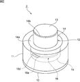
- FIG. 2 is a perspective view of the vibration device used in the first embodiment of the present invention.
- FIG. 3 is a front sectional view of the piezoelectric vibrator used in the first embodiment of the present invention.
- FIG. 4 is a schematic front cross-sectional view showing the right half of the connecting structure of the light transmitting body portion and the cylindrical vibrating body portion in the first embodiment of the present invention.
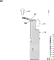
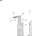
- FIG. 5 is a diagram showing a displacement distribution when the light transmitting body portion is flexibly oscillating in the first mode.
- FIG. 6 is a diagram illustrating a displacement distribution in the case where the light transmitting body portion is bending-vibrated in the second mode.
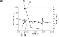
- FIG. 7 is a diagram illustrating the relationship between the resonance characteristics in the vibration device according to the first embodiment of the present invention, and the amount of displacement and the frequency in the transparent body.
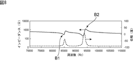
- FIG. 8 is a diagram showing the main part of the resonance characteristics and the phase characteristics shown in FIG.
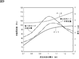
- FIG. 9 is a diagram illustrating the relationship between the thickness of the translucent part, the resonance frequency and displacement in the first mode, and the relationship between the resonance frequency and displacement in the second mode.
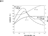
- FIG. 10 is a diagram illustrating the relationship between the thickness of the translucent part, the resonance frequency and displacement in the first mode, and the relationship between the resonance frequency and displacement in the second mode.
- FIG. 11 is a schematic front cross-sectional view showing a displacement distribution when the light transmitting body portion according to the first embodiment of the present invention vibrates in the first mode.
- FIG. 12 is a schematic front cross-sectional view showing a displacement distribution when the light transmitting body portion according to the first embodiment of the present invention vibrates in the second mode.
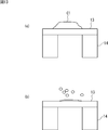
- FIG. 13A and FIG. 13B are schematic front cross-sectional views for explaining a process of removing water droplets in the vibration device according to the first embodiment of the present invention.
- FIGS. 14A to 14C are schematic front sectional views for explaining a process of removing water droplets in the vibration device according to the first embodiment.
- FIG. 15 is a front cross-sectional view showing a modification of the translucent part.
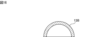
- FIG. 16 is a front cross-sectional view showing another modification of the translucent part.
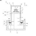
- FIG. 17 is a schematic front cross-sectional view for explaining the structure of the translucent body portion and the cylindrical vibration body portion of the vibration device according to the second embodiment of the present invention.
- FIG. 1 is a schematic front sectional view of a camera having a vibration device according to a first embodiment of the present invention.
- FIG. 2 is a perspective view of the vibration device.
- the camera 1 has a vibration device 2.
- a camera body 3 is accommodated in the vibration device 2.
- the camera body 3 has a cylindrical body member 4.
- the lower end of the main body member 4 is fixed to the base plate 10.
- An imaging unit 5 is fixed to the upper end of the main body member 4.
- a circuit 6 including an image sensor is built in the imaging unit 5.
- the lens module 7 is fixed so as to face the imaging unit 5.
- the lens module 7 is formed of a cylindrical body, and a plurality of lenses 9 are provided therein.
- the structure of the camera body 3 is not particularly limited as long as an object to be imaged located in front of the lens 9 can be imaged.
- the vibration device 2 includes a cylindrical case member 11, a cylindrical vibrating body portion 12, and a translucent body portion 13.
- the cylindrical case member 11 is cylindrical.
- the case member 11 may have other shapes such as a rectangular tube shape.
- the case member 11 is made of, for example, metal or synthetic resin.
- the lower end of the case member 11 is fixed to the base plate 10.
- An annular protrusion 11 a is provided on the upper end side of the case member 11.
- the annular protrusion 11 a protrudes radially inward of the case member 11.
- An annular recess 11b is provided on the upper surface of the protrusion 11a.
- the cylindrical vibrating body portion 12 includes a cylindrical member 14, a cylindrical fixing member 15, and a piezoelectric vibrator 16.
- the piezoelectric vibrator 16 is a cylindrical piezoelectric vibration element, and is composed of a Langevin vibrator, for example.
- the upper end of the fixing member 15 is screwed into the lower end of the cylindrical member 14. Thereby, the cylindrical piezoelectric vibrator 16 is sandwiched and fixed between the upper surface of the fixing member 15 and the lower surface of the cylindrical member 14.
- the cylindrical member 14 and the fixing member 15 are made of metal or synthetic resin.
- the cylindrical piezoelectric vibrator 16 has an annular piezoelectric element 16a.
- the annular piezoelectric element 16a includes annular piezoelectric plates 16a1 and 16a2.
- the direction indicated by the arrow is the polarization direction. That is, in the thickness direction, the polarization direction of the piezoelectric plate 16a1 is opposite to the polarization direction of the piezoelectric plate 16a2.
- a cylindrical terminal 16d is sandwiched between the piezoelectric plates 16a1 and 16a2.
- a cylindrical terminal 16e is sandwiched between the piezoelectric plate 16a1 and the second cylindrical member.
- the piezoelectric plates 16a1 and 16a2 are made of lead zirconate titanate piezoelectric ceramics. However, other piezoelectric ceramics or piezoelectric single crystals may be used. Electrodes (not shown) are formed on both surfaces of the piezoelectric plates 16a1 and 16a2.
- the cylindrical member 14 has a flange portion 14a protruding outward in the radial direction.
- the cylindrical member 14 is fixed to the case member 11 so that the lower surface of the flange portion 14a is positioned in the recess 11b.
- the cylindrical member 14 has a first end and a second end in the Z direction, which is the central axis direction of the cylindrical vibrating body portion 12. At the first end, the cylindrical member 14 has a distal end surface 14b.
- the front end surface 14 b is annular and surrounds the opening on the first end side of the tubular member 14.
- the outer peripheral part of the flat-plate-shaped translucent body part 13 is joined to the front end surface 14b.
- this bonding is achieved by an appropriate bonding method using a bonding material such as an adhesive. Therefore, the tip surface 14b constitutes the bonding interface in the present invention.
- the cylindrical member 14 has a thin portion 14e that is thinner on the first end side than the second end portion.
- the thin portion 14e constitutes a mode conversion coupling portion and has a function of increasing the amplitude.
- the translucent part 13 is made of glass, and the whole has translucency. However, the translucent part 13 may be translucent only in the part located in front of the lens 9, that is, the part corresponding to the field of view of the camera.
- the material constituting the translucent part 13 is not limited to glass, and translucent plastics may be used.
- the translucent part 13 is located further forward of the foremost lens 9 of the camera body 3.
- the vibration of the piezoelectric vibrator 16 vibrates so that the cylindrical vibrating body 12 to which the piezoelectric vibrator 16 is attached expands and contracts in the Z direction shown in FIG.
- the Z direction shown in FIG. 1 is a direction from the cylindrical vibrating body 12 toward the translucent body 13 in the central axis direction of the cylindrical vibrating body 12.
- the reverse phase direction in FIG. 1 is a direction orthogonal to the Z direction and is an X direction from the left side to the right side in FIG.
- the vibration of the cylindrical vibrating body portion 12 is not particularly limited as long as it is accompanied by a displacement in the Z direction.
- the piezoelectric vibrator 16 may be in a vibration mode in which the diameter is reduced and expanded as in so-called respiratory vibration.
- the distal end surface 14b of the cylindrical vibrating body portion 12 repeats displacement in the Z direction.
- the front end surface 14 b side located at the first end is the front in the Z direction
- the second end opposite to the first end is the rear in the Z direction.
- the vibration device 2 the displacement is repeated between a vibration state in which the distal end surface 14b of the cylindrical member 14 is positioned forward in the Z direction and a vibration state positioned in the rear in the Z direction.
- the light transmitting body portion 13 vibrates in the bending mode.
- this bending mode vibration water droplets adhering to the outer surface of the translucent part 13 can be removed by atomization.
- the vibration device 2 is characterized in that the light transmitting body portion 13 is fixed to the distal end surface 14b of the cylindrical member 14 so that the bending mode vibration node is located at the above-described bonding interface. . This will be described in more detail.
- the first mode and the second mode described below appear as the bending mode.
- FIG. 4 is a schematic front sectional view showing a half on the right side of the connection structure between the cylindrical vibrating body portion 12 and the translucent body portion 13.
- hatching is omitted. This is because hatching is used to express the displacement distribution in FIGS. 5 and 6 described below.
- FIG. 4 shows a stationary state.
- FIG. 5 shows a displacement distribution when the transparent body portion 13 is bending-vibrated in the first mode.
- the displacement distribution in FIGS. 5 and 6 shows that the displacement amount of each area shown by hatching in FIGS. 5 and 6 is the scale size shown on the right side of FIGS. Yes.
- the central maximum displacement portion is displaced in the same direction as indicated by an arrow A2.
- the distal end surface 14b and the central maximum displacement portion of the translucent body 13 are displaced in phase in the Z direction.
- the tip surface 14b that is, the bonding interface is hardly displaced. Therefore, in the first mode, the vibration node is located in the junction interface.
- FIG. 6 is a diagram showing a displacement distribution in the second mode.
- the central maximum displacement portion of the light transmitting member 13 is the Z direction as indicated by an arrow -A2. Displace backwards. That is, the front end surface 14b and the central maximum displacement portion of the translucent body 13 are displaced in opposite phases in the Z direction.
- the tip surface 14b that is, the bonding interface is displaced, and the vibration node is not located at the bonding interface.
- the displacement distribution shown in FIG. 6 is not the displacement distribution in the present embodiment.
- the feature of this embodiment is that the transparent body portion 13 is fixed to the cylindrical vibration body portion 12 so that the vibration nodes of both the first mode and the second mode are located at the joint interface. There is in being. This point will be described in more detail below.
- FIG. 7 shows the relationship between the resonance characteristics when the piezoelectric vibrator is driven and vibrated in the vibration device 2 of the first embodiment, and the amount of displacement and the frequency in the transparent body portion.
- FIG. 8 shows an enlarged main part of the resonance characteristics of FIG. 7 and shows phase characteristics.
- the arrow B1 indicates the resonance characteristic of the first mode
- the arrow B2 indicates the resonance characteristic in the second mode.
- the displacement amount at the frequency position of about 80,000 to 100,000 Hz in the displacement amount in FIG. 8 indicates the displacement amount in the first mode and the second mode.
- FIG. 9 shows the results when the length of the cylindrical member 14 is 21.1 mm and the radius R of the opening is 4.5 mm.
- FIG. 10 shows the results when the length of the cylindrical member 14 is 21.1 mm and the radius R of the opening is 4.25 mm.
- the resonance frequency of the first mode is Fr1
- the resonance frequency of the second mode is Fr2.
- the vibration node can be positioned in the bonding interface not only in the first mode but also in the second mode.
- FIG. 11 is a schematic front sectional view showing the displacement distribution in the first mode in the first embodiment
- FIG. 12 is a schematic front sectional view showing the displacement distribution in the second mode.
- the central maximum displacement portion of the tubular member 14 and the light transmitting body portion 13 expands and contracts in the Z direction in the same phase.
- the tip surface 14b at the bonding interface is hardly displaced, and the vibration node is located in the bonding interface.
- the cylindrical member 14 is made of SUS304, and its length is 21.1 mm. Moreover, the translucent part 13 consists of glass, and the thickness was 1.1 mm. The radius surrounded by the tip surface 14b was 4.5 mm in inner diameter.
- the vibration node of either the first mode or the second mode is adjusted.
- the resonance frequency Fr1 of the first mode is close to the resonance frequency Fr2 of the second mode.
- the displacement amount of the first mode and the second mode it can be seen that both of the displacement amounts of the above increase and show a peak value.
- the resonance frequency Fr1 of the first mode is close to the resonance frequency Fr2 of the second mode, more specifically, the absolute value of the resonance frequency difference Fr1-Fr2 with respect to (Fr1 + Fr2). It is desirable that the ratio is within ⁇ 10%. Thereby, a large amplitude can be obtained reliably.
- water droplets can be removed by the first mode vibration, the water droplets straddling the vibration node can be moved by the second mode vibration, and the water droplets can be joined. This will be described with reference to FIGS.
- FIG. 13A water droplets C ⁇ b> 1 are attached to the outer surface of the translucent part 13.
- the translucent body 13 is vibrated in the first mode.
- FIG. 13B the water droplets are atomized and removed.
- FIG. 14A small water droplets D1, D2, and D3 are attached to the surface of the translucent part 13.
- FIG.14 (b) water droplets coalesce.
- FIG. 14C the united large water droplets can be atomized and removed by vibrating the light transmitting member 13 in the first mode.
- the vibration device 2 of the present embodiment it is preferable to vibrate in the second mode and then vibrate in the first mode. More preferably, the step of driving in the first mode and the step of driving in the second mode are preferably repeated alternately. Thereby, water droplets adhering to the outer surface of the translucent part 13 can be more reliably removed.
- the light transmitting body portion 13 has a flat plate shape.
- the dome-shaped light transmitting body portions 13A and 13B are used. Also good.
- the dome-shaped translucent body portion 13A has a flange portion 13A1 on the outer peripheral edge. When such a flange portion 13A1 is provided, the lower surface of the flange portion 13A1 is joined to the distal end surface 14b of the cylindrical main body 14. Thereby, a bonding interface is formed.
- the cylindrical member 14 may have a mode conversion coupling portion 14c and a cylindrical main body 14d.
- the mode conversion coupling portion 14c also constitutes a thin portion in the present invention. Therefore, the amplitude can be increased.
- the tip in the Z direction of the mode conversion coupling portion 14 c is the tip of the cylindrical member 14. Therefore, the tip surface 14b is located at the tip of the mode conversion coupling portion 14c.
- the cylindrical main body 14 d is vibrated by breathing vibration or the like by driving the piezoelectric vibrator 16.
- the mode conversion coupling unit 14c converts this vibration mode into a vibration mode such as a stretching vibration in the Z direction.
- the dimension of the mode conversion coupling portion 14c so that the resonance frequency in the mode conversion coupling portion 14c matches the resonance frequency of the cylindrical body 14d. Thereby, the mode can be converted and the amplitude at the tip surface 14b can be further increased.
Landscapes
- Physics & Mathematics (AREA)
- General Physics & Mathematics (AREA)
- Engineering & Computer Science (AREA)
- Multimedia (AREA)
- Signal Processing (AREA)
- Optics & Photonics (AREA)
- Electromagnetism (AREA)
- Studio Devices (AREA)
- Camera Bodies And Camera Details Or Accessories (AREA)
- Structure And Mechanism Of Cameras (AREA)
- Lens Barrels (AREA)
- Apparatuses For Generation Of Mechanical Vibrations (AREA)
Abstract
接合界面における剥離を抑制しつつ、大きな振幅を得ることを可能とする、振動装置を得る。 筒状部材14と、筒状部材14に固定されている圧電振動子16とを有する筒状振動体部12と、筒状部材14の先端面14bに外周部が接合されており、かつレンズ9の前方に配置されている透光性部分を有する透光体部13とを備える、振動装置2。筒状振動体部12の振動により、透光体部13が屈曲モードで振動されるように構成されている。屈曲モードは、Z方向において透光体部13の中央最大変位部分と、先端面14bに連結されている外周部とが、同じ向きに変位する第1のモードと、逆向きに変位する第2のモードにおいて、先端面14bと外周部との接合界面内に第1のモード及び第2のモードのノードが位置するように、透光体部13の外周部が、筒状振動体部12の先端面14bに接合されている。
Description
本発明は、レンズを有するカメラ本体に用いられる振動装置及び振動装置の駆動方法、並びにカメラに関する。
車両搭載用カメラや、家屋の外に設けられるカメラは、雨に晒される。そのため、レンズの前方に、ガラスや透明プラスチックからなるカバーが設けられている。しかしながら、カバーに水滴が付着すると、視野がクリアでなくなる。
下記の特許文献1には、このような用途に用いられるドーム型カバーが開示されている。ドーム型カバーには、円筒部が連結されている。円筒部に圧電振動子が取り付けられている。ドーム型カバーに水滴が付着した場合に、圧電振動子により円筒部及びドーム型カバーを振動させる。それによって水滴が除去される。ドーム型カバーにおける振動のノード位置を変更することにより、液滴を霧化する位置を変更し得ることが記載されている。
下記の特許文献2には、カメラ本体の前方に超音波トランスデューサ、接着剤層及び外部レンズが配置されている。超音波トランスデューサを駆動することにより、外部レンズを振動させる。それによって、外部レンズに付着した水滴が除去される。
特許文献1や特許文献2において、水滴を確実に除去するには、ドーム型カバーや外部レンズを大きく振動させる必要があった。他方、特許文献1において、ドーム型カバーを大きく振動させようとすると、ドーム型カバーと、円筒部との接合界面において剥離するおそれがあった。
特許文献2においても、外部レンズを大きく駆動させるために、超音波トランスデューサにおいて大きな振動を発生させると、外部レンズと超音波トランスデューサとの接合界面において、剥離が生じるおそれがあった。
本発明の目的は、接合界面における剥離を抑制しつつ、大きな振幅を得ることを可能とする、振動装置及び振動装置の駆動方法を提供することにある。
本発明に係る振動装置は、レンズを有するカメラ本体に用いられる振動装置であって、第1の端部及び第2の端部を有し、前記第1の端部において開口を囲む先端面を有し、前記第1の端部側において、前記第2の端部よりも厚みの薄い薄肉部を有する筒状部材と、前記筒状部材に固定されている圧電振動子とを有する、筒状振動体部と、前記開口を覆うように、前記筒状部材の前記先端面に外周部が接合されており、かつ前記レンズの前方に配置されている透光性部分を有する、透光体部とを備え、前記筒状振動体部の振動により、前記透光体部が屈曲モードで振動されるように構成されており、前記屈曲モードが、前記屈曲モードの振動における前記透光体部の中央最大変位部分と、前記先端面に連結されている前記外周部とが、前記筒状振動体部の中心軸方向であるZ方向において同じ向きに変位する第1のモードと、逆向きに変位する第2のモードとを有し、前記先端面と前記外周部との接合界面内に前記第1のモード及び前記第2のモードのノードが位置するように、前記透光体部の前記外周部が前記筒状振動体部の前記先端面に接合されている。
本発明に係る振動装置のある特定の局面では、前記筒状振動体部を、前記Z方向に変位させるように、前記圧電振動子が設けられている。
本発明に係る振動装置の他の特定の局面では、前記筒状部材が筒状本体と、前記筒状本体に連結されており、前記薄肉部を有する筒状のモード変換結合部とを有し、前記モード変換結合部の前記筒状本体に連結されている側とは反対側の端部が、前記第1の端部であり、前記開口及び前記先端面を有する。この場合には、透光体部における振幅をより一層大きくすることができる。
本発明に係る振動装置のさらに他の特定の局面では、前記圧電振動子が筒状である。
本発明に係る振動装置のさらに別の特定の局面では、前記筒状振動体部が、円筒状である。この場合には、筒状振動体部のZ方向の振動だけでなく、呼吸振動をも利用することができる。
本発明に係る振動装置の駆動方法は、本発明に従って構成されている振動装置の駆動方法であって、前記第1のモード及び前記第2のモードの少なくとも一方で前記透光体部を振動させるとともに、前記第1のモードにおける振動のノード及び前記第2のモードにおける振動のノードが、前記接合界面内に位置するように、前記振動装置を駆動する。
本発明に係る振動装置の駆動方法のある特定の局面では、前記第1のモードの共振周波数と、前記第2のモードの共振周波数の差が小さくなるように、前記第1のモード及び前記第2のモードの少なくとも一方のモードで、前記透光体部を振動させる。
本発明に係る振動装置の駆動方法の他の特定の局面では、前記第1のモードで振動させる工程と、前記第2のモードで振動させる工程とを交互に繰り返す。
本発明に係るカメラは、本発明に従って構成されている振動装置を有する。
本発明に係る振動装置及びその駆動方法によれば、接合界面における剥離を効果的に抑制することができる。従って、透光体部をより大きな振幅で振動させることが可能となる。
以下、図面を参照しつつ、本発明の具体的な実施形態を説明することにより、本発明を明らかにする。
なお、本明細書に記載の各実施形態は、例示的なものであり、異なる実施形態間において、構成の部分的な置換または組み合わせが可能であることを指摘しておく。
図1は、本発明の第1の実施形態に係る振動装置を有するカメラの略図的正面断面図である。図2は、この振動装置の斜視図である。カメラ1は、振動装置2を有する。振動装置2内には、カメラ本体3が収納されている。
カメラ本体3は、筒状の本体部材4を有する。本体部材4の下端は、ベースプレート10に固定されている。本体部材4の上端に撮像部5が固定されている。撮像部5内には、撮像素子を含む回路6が内蔵されている。撮像部5に対向するように、レンズモジュール7が固定されている。レンズモジュール7は、筒状体からなり、内部に複数のレンズ9が設けられている。
上記カメラ本体3の構造は、レンズ9の前方に位置している被撮像物を撮像し得る限り特に限定されるものではない。
振動装置2は、筒状のケース部材11と、筒状振動体部12と、透光体部13とを有する。筒状のケース部材11は円筒状である。もっとも、ケース部材11は、角筒状などの他の形状であってもよい。ケース部材11は、例えば金属や合成樹脂からなる。
ケース部材11の下端がベースプレート10に固定されている。ケース部材11の上端側には、環状の突出部11aが設けられている。環状の突出部11aは、ケース部材11の径方向内側に突出している。突出部11aの上面に、円環状の凹部11bが設けられている。
筒状振動体部12は、筒状部材14と、筒状の固定部材15と、圧電振動子16とを有する。圧電振動子16は、筒状の圧電振動素子であり、例えばランジュバン型振動子などにより構成される。
固定部材15の上端が、筒状部材14の下端にねじ込まれている。それによって、筒状の圧電振動子16が固定部材15の上面と、筒状部材14の下面との間に挟持されて固定されている。上記筒状部材14及び上記固定部材15は、金属や合成樹脂からなる。
筒状の圧電振動子16は、円環状の圧電素子16aを有する。図3に示すように、円環状の圧電素子16aは、円環状の圧電板16a1,16a2を有する。圧電板16a1,16a2は、図示の矢印方向が分極方向である。すなわち、厚み方向において、圧電板16a1の分極方向と圧電板16a2の分極方向とは逆方向となっている。圧電板16a1,16a2間に、筒状の端子16dが挟持されている。また、圧電板16a1と第2の筒部材との間に、筒状の端子16eが挟持されている。
圧電板16a1,16a2は、チタン酸ジルコン酸鉛系圧電セラミックスからなる。もっとも、他の圧電セラミックスや圧電単結晶が用いられてもよい。圧電板16a1,16a2の両面には、図示しない電極が形成されている。
図1に戻り、上記筒状部材14は、径方向外側に突出しているフランジ部14aを有する。フランジ部14aの下面が、凹部11b内に位置するようにして、筒状部材14が、ケース部材11に固定されている。
筒状部材14は、筒状振動体部12の中心軸方向であるZ方向において、第1の端部と、第2の端部とを有する。この第1の端部において、筒状部材14は、先端面14bを有する。先端面14bは、円環状であり、筒状部材14の第1の端部側の開口を囲んでいる。先端面14bに、平板状の透光体部13の外周部が接合されている。この接合は、特に図示はしないが、接着剤などの接合材を用いた適宜の接合方法により果たされている。従って、上記先端面14bが、本発明における接合界面を構成している。筒状部材14は、第1の端部側において、第2の端部よりも厚みが薄い、薄肉部14eを有する。薄肉部14eは、モード変換結合部を構成しており、かつ振幅を増大させる機能を有する。
透光体部13は、ガラスからなり、その全体が透光性を有する。もっとも、透光体部13は、レンズ9の前方に位置している部分、すなわちカメラの視野に相当する部分のみが透光性を有していてもよい。
透光体部13を構成する材料は、ガラスに限らず、透光性プラスチックスなどが用いられてもよい。
透光体部13は、上記カメラ本体3の最前方のレンズ9のさらに前方に位置している。
圧電振動子16の振動により、圧電振動子16が取り付けられている筒状振動体部12が図1に示すZ方向において伸縮するように振動する。図1に示すZ方向とは、筒状振動体部12の中心軸方向において、筒状振動体部12から透光体部13に向かう方向である。また、図1の逆相方向とは、上記Z方向と直交する方向であって、図1の左側から右側に向かうX方向をいうものとする。この場合、筒状振動体部12の振動は、Z方向の変位を伴う限り、特に限定されない。例えば、圧電振動子16がいわゆる呼吸振動のように縮径拡径状態とを交互による振動モードであってもよい。その場合においても、結果として、筒状振動体部12の先端面14bは、Z方向に変位を繰り返すこととなる。筒状部材14の中心軸方向において、第1の端部に位置している先端面14b側をZ方向前方、第1の端部とは反対側の第2の端部側をZ方向後方とする。
振動装置2では、筒状部材14の先端面14bがZ方向前方に位置している振動姿態と、Z方向後方に位置している振動姿態との間で変位を繰り返す。その結果、透光体部13が屈曲モード振動する。この屈曲モード振動により、透光体部13の外表面に付着した水滴を霧化により除去することができる。
振動装置2の特徴は、上記屈曲モードの振動のノードが、前述した接合界面に位置しているように、透光体部13が筒状部材14の先端面14bに固定されていることにある。これをより詳細に説明する。
上記のように筒状部材14の振動により、透光体部13が屈曲モード振動する場合、透光体部13の主面の中央が最も大きく変位する。この最も大きく変位する部分を、中央最大変位部分とする。筒状部材14の先端面14bに接合されている外周部において、変位は最も小さくなっている。
この場合、屈曲モードとしては、以下に述べる第1のモードと、第2のモードが出現する。
図4~図6を参照して、上記第1のモード及び第2のモード状態の変位を説明する。
図4は、上記筒状振動体部12を、透光体部13との連結構造の右側の半分を示す略図的正面断面図である。図4では、ハッチングは省略されている。これは、次に述べる図5及び図6において、変位分布の表現にハッチングを用いているためである。図4では、筒状振動体部12及び透光体部13の一点鎖線Aの右側で示す部分のみが図示されている。図4は静止状態を示す。
図5は、第1のモードで透光体部13が屈曲振動している場合の変位分布を示す。なお、図5及び図6における変位分布は、図5及び図6にハッチングで示した各領域の変位量が、図5及び図6の右側に示したスケールの大きさとなっていることを示している。第1のモードでは、先端面14bがZ方向において、Z方向前面側に変位した場合、中央最大変位部分は、矢印A2で示すように、同じ方向に変位する。第1のモードでは、先端面14bと、透光体部13の中央最大変位部分とが、Z方向において同相変位することとなる。この場合、図5から明らかなように、先端面14bすなわち接合界面はほとんど変位していない。従って、第1のモードでは、振動のノードは接合界面内に位置している。
他方、図6は、第2のモードの場合の変位分布を示す図である。図6の矢印A1で示すように、先端面14bがZ方向前方に変位した場合、第2のモードでは、透光体部13の中央最大変位部分は、矢印-A2で示すように、Z方向後方に変位する。すなわち、先端面14bと、透光体部13の中央最大変位部分とはZ方向において逆相で変位する。
なお、図6では、先端面14b、すなわち接合界面が変位しており、振動のノードが接合界面に位置していない。この図6に示す変位分布は、本実施形態の場合の変位分布ではない。本実施形態の特徴は、上記第1のモード及び第2のモードのいずれの振動のノードも、上記接合界面に位置するように、透光体部13が、筒状振動体部12に固定されていることにある。この点について、以下においてより詳細に説明する。
上記第1の実施形態の振動装置2において、圧電振動子を駆動し、振動させた場合の共振特性と、透光体部における変位量と周波数との関係を図7に示す。また、図8は、図7の共振特性の要部を拡大して示し、かつ位相特性を示す。
図7及び8における矢印B1が、上記第1のモードの共振特性であり、矢印B2が、第2のモードにおける共振特性を示す。図8の変位量における約80000~100000Hz周波数位置における変位量が、上記第1のモード及び第2のモードにおける変位量を示す。
本願発明者らは、上記第1のモード及び第2のモードが出現することに鑑み、透光体部13の厚み、筒状部材14の長さ及び内径を変化させ、種々検討した。図9は、筒状部材14の長さが21.1mm、開口部の半径Rが4.5mmの場合の結果を示す。図10は、筒状部材14の長さが21.1mm、開口部の半径Rが4.25mmの場合の結果を示す。
図9及び図10において、第1のモードの共振周波数をFr1、第2のモードの共振周波数をFr2とする。
図9及び図10から明らかなように、透光体部13の厚みを変化させた場合や、開口部の半径Rを変化させた場合に、第1のモードの共振周波数Fr1、第2のモードの共振周波数Fr2及び第1のモード及び第2のモードの変位量が変化することがわかる。そして、この透光体部の厚み、開口部の半径R、さらに、筒状部材14のZ方向に沿う寸法である長さ、透光体部13、及び筒状部材14の材質を調整することにより、第1のモードだけでなく、第2のモードにおいても、接合界面内に振動のノードを位置させることができる。
図11は、上記第1の実施形態における第1のモードにおける変位分布を示す模式的正面断面図であり、図12は、第2のモードにおける変位分布を示す模式的正面断面図である。図11に示すように、第1のモードにおいて、矢印A1,A2で示すように、筒状部材14及び透光体部13の中央最大変位部分は、同相でZ方向において伸縮する。そして、図11から明らかなように、接合界面にある先端面14bがほとんど変位しておらず、振動のノードが接合界面内に位置している。
また、図12に示すように、第2のモードでは、矢印A1,-A2で示すように、筒状部材14と、透光体部13の中央最大変位部分とは、Z方向において逆相で変位する。そして、図12では、接合界面がほとんど変位しておらず、従って、第2のモードにおいても振動のノードが接合界面内に位置していることがわかる。
本実施形態では、筒状部材14がSUS304からなり、その長さは21.1mmとされている。また、透光体部13はガラスからなり、その厚みは1.1mmとした。また、先端面14bが囲んでいる半径は内径を4.5mmとした。
上記のように、筒状部材14及び透光体部13の材質に応じて、厚みや長さなどの各寸法を調整することにより、第1のモード及び第2のモードのいずれの振動のノードも接合界面に位置させることができる。
よって、上記実施形態の振動装置では、駆動に際し、透光体部13と筒状部材14との接合界面における剥離が生じ難い。そのため、より大きな振幅で透光体部13を振動させることができる。よって、透光体部13の表面に付着した水滴をより確実に除去することができる。ところで、第1のモードの共振周波数Fr1と、第2のモードの共振周波数Fr2は、接近していることが好ましい。図9及び図10から明らかなように、第1のモードの共振周波数Fr1と、第2のモードの共振周波数Fr2とが接近している領域では、第1のモードの変位量及び第2のモードの変位量の双方が大きくなり、ピーク値を示すことがわかる。従って、好ましくは、第1のモードの共振周波数Fr1と、第2のモードの共振周波数Fr2とが接近していること、より具体的には共振周波数差Fr1-Fr2の絶対値の(Fr1+Fr2)に対する割合が±10%以内とすることが望ましい。それによって、大きな振幅を確実に得ることができる。
上記実施形態の振動装置2では、第1のモードの振動により、水滴を除去し、第2のモードの振動で振動のノードを跨ぐ水滴を移動させ、水滴同士を合着させることができる。これを、図13及び図14を参照して説明する。
図13(a)では、透光体部13の外表面に、水滴C1が付着している。この状態で、第1のモードで透光体部13を振動させる。その結果、図13(b)に示すように、水滴が霧化され、除去されていく。他方図14(a)では、透光体部13の表面に、小さな水滴D1,D2,D3が付着している。第2のモードで透光体部13を振動させると、ノードを跨いでいる水滴D2,D3などが移動する。そのため、図14(b)に示すように、水滴同士が合着する。しかる後図14(c)に示すように、第1のモードで透光体部13を振動させることにより、合着した大きな水滴を霧化し、除去することができる。
従って、本実施形態の振動装置2では、第2のモードで振動させ、次に第1のモードで振動させることが好ましい。また、より好ましくは、第1のモードで駆動する工程と、第2のモードで駆動する工程とを交互に繰り返すことが好ましい。それによって、透光体部13の外表面に付着した水滴をより確実に除去することができる。
なお、第1の実施形態の振動装置2では、透光体部13は、平板状であったが、図15及び図16に示すように、ドーム状の透光体部13A,13Bを用いてもよい。また、図15では、ドーム状の透光体部13Aは、外周縁にフランジ部13A1を有する。このようなフランジ部13A1を有する場合、フランジ部13A1の下面が、筒状本体14の先端面14bに接合される。それによって、接合界面が構成される。
また、図17に示す第2の実施形態のように、筒状部材14が、モード変換結合部14cと、筒状本体14dとを有していてもよい。モード変換結合部14cは、本発明における薄肉部をも構成している。よって振幅を大きくし得る。ここでは、モード変換結合部14cのZ方向先端が、筒状部材14の先端となる。従って、モード変換結合部14cの先端に先端面14bが位置している。この場合、筒状本体14dは、圧電振動子16を駆動することにより、呼吸振動などで振動される。モード変換結合部14cは、この振動モードをZ方向の伸縮振動などの振動モードに変換する。その場合、モード変換結合部14cの寸法を調整し、モード変換結合部14cにおける共振周波数と、筒状本体14dの共振周波数とを一致させることが好ましい。それによって、モードを変換し、先端面14bにおける振幅をより一層大きくすることができる。
1…カメラ
2…振動装置
3…カメラ本体
4…本体部材
5…撮像部
6…回路
7…レンズモジュール
9…レンズ
10…ベースプレート
11…ケース部材
11a…突出部
11b…凹部
12…筒状振動体部
13…透光体部
13A,13B…透光体部
13A1…フランジ部
14…筒状部材
14a…フランジ部
14b…先端面
14c…モード変換結合部
14d…筒状本体
14e…薄肉部
15…固定部材
16…圧電振動子
16a…圧電素子
16a1,16a2…圧電板
16d,16e…端子
2…振動装置
3…カメラ本体
4…本体部材
5…撮像部
6…回路
7…レンズモジュール
9…レンズ
10…ベースプレート
11…ケース部材
11a…突出部
11b…凹部
12…筒状振動体部
13…透光体部
13A,13B…透光体部
13A1…フランジ部
14…筒状部材
14a…フランジ部
14b…先端面
14c…モード変換結合部
14d…筒状本体
14e…薄肉部
15…固定部材
16…圧電振動子
16a…圧電素子
16a1,16a2…圧電板
16d,16e…端子
Claims (9)
- レンズを有するカメラ本体に用いられる振動装置であって、
第1の端部及び第2の端部を有し、前記第1の端部において開口を囲む先端面を有し、前記第1の端部において、前記第2の端部よりも厚みが薄い薄肉部を有する筒状部材と、前記筒状部材に固定されている圧電振動子とを有する、筒状振動体部と、
前記開口を覆うように、前記筒状部材の前記先端面に外周部が接合されており、かつ前記レンズの前方に配置されている透光性部分を有する、透光体部とを備え、
前記筒状振動体部の振動により、前記透光体部が屈曲モードで振動されるように構成されており、
前記屈曲モードが、前記屈曲モードの振動における前記透光体部の中央最大変位部分と、前記先端面に連結されている前記外周部とが、前記筒状振動体部の中心軸方向であるZ方向において同じ向きに変位する第1のモードと、逆向きに変位する第2のモードとを有し、前記先端面と前記外周部との接合界面内に前記第1のモード及び前記第2のモードのノードが位置するように、前記透光体部の前記外周部が前記筒状振動体部の前記先端面に接合されている、振動装置。 - 前記筒状振動体部を、前記Z方向に変位させるように、前記圧電振動子が設けられている、請求項1に記載の振動装置。
- 前記筒状部材が筒状本体と、
前記筒状本体に連結されており、前記薄肉部を有する筒状のモード変換結合部とを有し、
前記モード変換結合部の前記筒状本体に連結されている側とは反対側の端部が、前記第1の端部であり、前記開口及び前記先端面を有する、請求項1または2に記載の振動装置。 - 前記圧電振動子が筒状である、請求項1~3のいずれか1項に記載の振動装置。
- 前記筒状振動体部が、円筒状である、請求項1~4のいずれか1項に記載の振動装置。
- 請求項1~5のいずれか1項に記載の振動装置の駆動方法であって、前記第1のモード及び前記第2のモードの少なくとも一方で前記透光体部を振動させるとともに、前記第1のモードにおける振動のノード及び前記第2のモードにおける振動のノードが、前記接合界面内に位置するように、前記振動装置を駆動する、振動装置の駆動方法。
- 前記第1のモードの共振周波数と、前記第2のモードの共振周波数の差が小さくなるように、前記第1のモード及び前記第2のモードの少なくとも一方のモードで、前記透光体部を振動させる、請求項6に記載の振動装置の駆動方法。
- 前記第1のモードで振動させる工程と、前記第2のモードで振動させる工程とを交互に繰り返す、請求項6または7に記載の振動装置の駆動方法。
- 請求項1~5のいずれか1項に記載の振動装置を有する、カメラ。
Priority Applications (4)
| Application Number | Priority Date | Filing Date | Title |
|---|---|---|---|
| JP2018502552A JP6508415B2 (ja) | 2016-03-03 | 2017-01-10 | 振動装置及びその駆動方法、並びにカメラ |
| CN201780005499.7A CN108474998B (zh) | 2016-03-03 | 2017-01-10 | 振动装置及其驱动方法、以及摄像头 |
| DE112017001092.6T DE112017001092B4 (de) | 2016-03-03 | 2017-01-10 | Schwingungsvorrichtung, verfahren zum ansteuern derselben sowie kamera |
| US16/008,071 US10444495B2 (en) | 2016-03-03 | 2018-06-14 | Vibration device, method of driving the same, and camera |
Applications Claiming Priority (2)
| Application Number | Priority Date | Filing Date | Title |
|---|---|---|---|
| JP2016-040994 | 2016-03-03 | ||
| JP2016040994 | 2016-03-03 |
Related Child Applications (1)
| Application Number | Title | Priority Date | Filing Date |
|---|---|---|---|
| US16/008,071 Continuation US10444495B2 (en) | 2016-03-03 | 2018-06-14 | Vibration device, method of driving the same, and camera |
Publications (1)
| Publication Number | Publication Date |
|---|---|
| WO2017149933A1 true WO2017149933A1 (ja) | 2017-09-08 |
Family
ID=59742833
Family Applications (1)
| Application Number | Title | Priority Date | Filing Date |
|---|---|---|---|
| PCT/JP2017/000467 Ceased WO2017149933A1 (ja) | 2016-03-03 | 2017-01-10 | 振動装置及びその駆動方法、並びにカメラ |
Country Status (5)
| Country | Link |
|---|---|
| US (1) | US10444495B2 (ja) |
| JP (1) | JP6508415B2 (ja) |
| CN (1) | CN108474998B (ja) |
| DE (1) | DE112017001092B4 (ja) |
| WO (1) | WO2017149933A1 (ja) |
Cited By (7)
| Publication number | Priority date | Publication date | Assignee | Title |
|---|---|---|---|---|
| US20180095272A1 (en) * | 2015-08-04 | 2018-04-05 | Murata Manufacturing Co., Ltd. | Vibration device and camera |
| WO2019130629A1 (ja) * | 2017-12-27 | 2019-07-04 | 株式会社村田製作所 | 振動装置及び光学検出装置 |
| WO2020003571A1 (ja) * | 2018-06-28 | 2020-01-02 | 株式会社村田製作所 | 振動装置 |
| WO2020137262A1 (ja) * | 2018-12-28 | 2020-07-02 | 株式会社村田製作所 | 振動装置及び光学検出装置 |
| WO2021210208A1 (ja) * | 2020-04-17 | 2021-10-21 | 株式会社村田製作所 | 振動装置 |
| JPWO2021210208A1 (ja) * | 2020-04-17 | 2021-10-21 | ||
| EP3838426A4 (en) * | 2018-09-28 | 2022-06-22 | Murata Manufacturing Co., Ltd. | VIBRATION DEVICE AND OPTICAL DETECTION DEVICE |
Families Citing this family (9)
| Publication number | Priority date | Publication date | Assignee | Title |
|---|---|---|---|---|
| JP6597897B2 (ja) * | 2016-06-24 | 2019-10-30 | 株式会社村田製作所 | 振動装置及び撮像装置 |
| WO2018100796A1 (ja) * | 2016-11-30 | 2018-06-07 | 株式会社村田製作所 | 振動装置、カメラ用水滴除去装置及びカメラ |
| CN113775887A (zh) * | 2018-02-11 | 2021-12-10 | 深圳市大疆创新科技有限公司 | 云台及其控制方法、无人机 |
| WO2021100227A1 (ja) * | 2019-11-22 | 2021-05-27 | 株式会社村田製作所 | 振動装置、および振動装置を備える撮像ユニット |
| JP7067679B2 (ja) * | 2020-03-19 | 2022-05-16 | 株式会社村田製作所 | 振動装置及び振動制御方法 |
| CN113891768B (zh) * | 2020-04-27 | 2023-06-30 | 株式会社村田制作所 | 振动装置 |
| JP7173333B2 (ja) * | 2020-05-15 | 2022-11-16 | 株式会社村田製作所 | 振動装置 |
| TWI732622B (zh) * | 2020-07-08 | 2021-07-01 | 國立臺灣海洋大學 | 水下鏡頭之機械式生物附著防止裝置 |
| CN112866526A (zh) * | 2021-01-07 | 2021-05-28 | 南昌欧菲光电技术有限公司 | 功率控制电路、镜头组件和电子设备 |
Citations (5)
| Publication number | Priority date | Publication date | Assignee | Title |
|---|---|---|---|---|
| JP2003330082A (ja) * | 2002-05-17 | 2003-11-19 | Olympus Optical Co Ltd | 電子撮像装置 |
| JP2004064555A (ja) * | 2002-07-30 | 2004-02-26 | Olympus Corp | カメラ及びこれに用いる撮像素子ユニット |
| JP2012090090A (ja) * | 2010-10-20 | 2012-05-10 | Olympus Imaging Corp | 振動装置及びそれを用いた画像機器 |
| JP2012138768A (ja) * | 2010-12-27 | 2012-07-19 | Hitachi Kokusai Electric Inc | ドーム型監視カメラシステム |
| JP2013080177A (ja) * | 2011-10-05 | 2013-05-02 | Aisin Seiki Co Ltd | 水滴除去機能付カメラ |
Family Cites Families (16)
| Publication number | Priority date | Publication date | Assignee | Title |
|---|---|---|---|---|
| JP3700559B2 (ja) * | 1999-12-16 | 2005-09-28 | 株式会社村田製作所 | 圧電音響部品およびその製造方法 |
| US7492408B2 (en) | 2002-05-17 | 2009-02-17 | Olympus Corporation | Electronic imaging apparatus with anti-dust function |
| US7324149B2 (en) | 2002-05-20 | 2008-01-29 | Olympus Optical Co., Ltd. | Camera and image pick-up device unit having an optical member that is vibrated to remove dust |
| JP2007082062A (ja) | 2005-09-16 | 2007-03-29 | Denso Corp | 水滴除去装置 |
| JP5154369B2 (ja) * | 2008-11-06 | 2013-02-27 | 三星電子株式会社 | 撮像素子ユニット及び撮像装置 |
| JP4648984B2 (ja) * | 2008-12-26 | 2011-03-09 | オリンパスイメージング株式会社 | 振動装置及びそれを用いた画像機器 |
| JP2012114728A (ja) * | 2010-11-25 | 2012-06-14 | Olympus Imaging Corp | 撮像装置 |
| WO2012129521A1 (en) * | 2011-03-23 | 2012-09-27 | Gentex Corporation | Lens cleaning apparatus |
| US9376066B2 (en) | 2011-04-18 | 2016-06-28 | Magna Electronics, Inc. | Vehicular camera with variable focus capability |
| JP6025446B2 (ja) * | 2012-08-10 | 2016-11-16 | キヤノン株式会社 | 振動型アクチュエータ、撮像装置および、振動型アクチュエータを備えた装置 |
| CN104871328A (zh) * | 2012-12-21 | 2015-08-26 | 佳能株式会社 | 振动波驱动设备、图像拾取设备、光学装置、液体排出设备和电子装置 |
| JP6107520B2 (ja) * | 2013-07-31 | 2017-04-05 | ブラザー工業株式会社 | 圧電アクチュエータ及び液体吐出装置 |
| US10401618B2 (en) * | 2015-03-11 | 2019-09-03 | Texas Instruments Incorporated | Ultrasonic lens cleaning system with current sensing |
| CN107852449B (zh) * | 2015-08-04 | 2020-08-18 | 株式会社村田制作所 | 振动装置以及摄像头 |
| DE112016004551T5 (de) * | 2015-12-24 | 2018-07-12 | Murata Manufacturing Co., Ltd. | Schwingvorrichtung, verfahren zum ansteuern derselben sowie kamera |
| DE112016005987B4 (de) * | 2015-12-25 | 2023-02-16 | Murata Manufacturing Co., Ltd. | Schwingungsvorrichtung und Kamera |
-
2017
- 2017-01-10 CN CN201780005499.7A patent/CN108474998B/zh active Active
- 2017-01-10 DE DE112017001092.6T patent/DE112017001092B4/de active Active
- 2017-01-10 WO PCT/JP2017/000467 patent/WO2017149933A1/ja not_active Ceased
- 2017-01-10 JP JP2018502552A patent/JP6508415B2/ja active Active
-
2018
- 2018-06-14 US US16/008,071 patent/US10444495B2/en active Active
Patent Citations (5)
| Publication number | Priority date | Publication date | Assignee | Title |
|---|---|---|---|---|
| JP2003330082A (ja) * | 2002-05-17 | 2003-11-19 | Olympus Optical Co Ltd | 電子撮像装置 |
| JP2004064555A (ja) * | 2002-07-30 | 2004-02-26 | Olympus Corp | カメラ及びこれに用いる撮像素子ユニット |
| JP2012090090A (ja) * | 2010-10-20 | 2012-05-10 | Olympus Imaging Corp | 振動装置及びそれを用いた画像機器 |
| JP2012138768A (ja) * | 2010-12-27 | 2012-07-19 | Hitachi Kokusai Electric Inc | ドーム型監視カメラシステム |
| JP2013080177A (ja) * | 2011-10-05 | 2013-05-02 | Aisin Seiki Co Ltd | 水滴除去機能付カメラ |
Cited By (17)
| Publication number | Priority date | Publication date | Assignee | Title |
|---|---|---|---|---|
| US20180095272A1 (en) * | 2015-08-04 | 2018-04-05 | Murata Manufacturing Co., Ltd. | Vibration device and camera |
| US10156719B2 (en) * | 2015-08-04 | 2018-12-18 | Murata Manufacturing Co., Ltd. | Vibration device and camera |
| US11503190B2 (en) | 2017-12-27 | 2022-11-15 | Murata Manufacturing Co., Ltd. | Vibration device and optical detection device |
| EP3668079A4 (en) * | 2017-12-27 | 2021-05-26 | Murata Manufacturing Co., Ltd. | VIBRATION DEVICE AND OPTICAL DETECTION DEVICE |
| WO2019130629A1 (ja) * | 2017-12-27 | 2019-07-04 | 株式会社村田製作所 | 振動装置及び光学検出装置 |
| JPWO2019130629A1 (ja) * | 2017-12-27 | 2020-07-27 | 株式会社村田製作所 | 振動装置及び光学検出装置 |
| CN112004614A (zh) * | 2018-06-28 | 2020-11-27 | 株式会社村田制作所 | 振动装置 |
| JPWO2020003571A1 (ja) * | 2018-06-28 | 2021-02-15 | 株式会社村田製作所 | 振動装置 |
| WO2020003571A1 (ja) * | 2018-06-28 | 2020-01-02 | 株式会社村田製作所 | 振動装置 |
| US11745219B2 (en) | 2018-06-28 | 2023-09-05 | Murata Manufacturing Co., Ltd. | Vibration apparatus |
| EP3838426A4 (en) * | 2018-09-28 | 2022-06-22 | Murata Manufacturing Co., Ltd. | VIBRATION DEVICE AND OPTICAL DETECTION DEVICE |
| US11980914B2 (en) | 2018-09-28 | 2024-05-14 | Murata Manufacturing Co., Ltd. | Vibrating device and optical detection apparatus |
| WO2020137262A1 (ja) * | 2018-12-28 | 2020-07-02 | 株式会社村田製作所 | 振動装置及び光学検出装置 |
| WO2021210208A1 (ja) * | 2020-04-17 | 2021-10-21 | 株式会社村田製作所 | 振動装置 |
| JPWO2021210208A1 (ja) * | 2020-04-17 | 2021-10-21 | ||
| JP7205622B2 (ja) | 2020-04-17 | 2023-01-17 | 株式会社村田製作所 | 振動装置 |
| US12436383B2 (en) | 2020-04-17 | 2025-10-07 | Murata Manufacturing Co., Ltd. | Vibration device |
Also Published As
| Publication number | Publication date |
|---|---|
| JP6508415B2 (ja) | 2019-05-08 |
| CN108474998A (zh) | 2018-08-31 |
| JPWO2017149933A1 (ja) | 2018-09-20 |
| DE112017001092T5 (de) | 2018-11-29 |
| DE112017001092B4 (de) | 2022-10-20 |
| CN108474998B (zh) | 2020-10-30 |
| US20180292646A1 (en) | 2018-10-11 |
| US10444495B2 (en) | 2019-10-15 |
Similar Documents
| Publication | Publication Date | Title |
|---|---|---|
| WO2017149933A1 (ja) | 振動装置及びその駆動方法、並びにカメラ | |
| EP3623059B1 (en) | Vibration device | |
| US11012597B2 (en) | Vibrating device and optical detector device | |
| JP6665948B2 (ja) | 振動装置、カメラ用水滴除去装置及びカメラ | |
| JP6418330B2 (ja) | 振動装置及びカメラ | |
| CN109076152B (zh) | 振动装置以及摄像装置 | |
| JP6819844B1 (ja) | 振動装置、および振動装置を備える撮像ユニット | |
| EP3731014A1 (en) | Vibration device and optical detection device | |
| CN109643044B (zh) | 振动装置、摄像机用水滴去除装置以及摄像机 | |
| WO2017110563A1 (ja) | 振動装置及びその駆動方法並びにカメラ | |
| US11770078B2 (en) | Vibration device and driving device | |
| WO2023100397A1 (ja) | 光学モジュールおよび光学装置 | |
| WO2024084728A1 (ja) | 光学装置、および光学装置を備える撮像ユニット | |
| WO2020137262A1 (ja) | 振動装置及び光学検出装置 | |
| WO1984000821A1 (fr) | Generateur d'onde ultrasonore |
Legal Events
| Date | Code | Title | Description |
|---|---|---|---|
| ENP | Entry into the national phase |
Ref document number: 2018502552 Country of ref document: JP Kind code of ref document: A |
|
| 121 | Ep: the epo has been informed by wipo that ep was designated in this application |
Ref document number: 17759405 Country of ref document: EP Kind code of ref document: A1 |
|
| 122 | Ep: pct application non-entry in european phase |
Ref document number: 17759405 Country of ref document: EP Kind code of ref document: A1 |