WO2017149847A1 - クレーン装置のワイヤロープ絡まり防止構造 - Google Patents
クレーン装置のワイヤロープ絡まり防止構造 Download PDFInfo
- Publication number
- WO2017149847A1 WO2017149847A1 PCT/JP2016/083835 JP2016083835W WO2017149847A1 WO 2017149847 A1 WO2017149847 A1 WO 2017149847A1 JP 2016083835 W JP2016083835 W JP 2016083835W WO 2017149847 A1 WO2017149847 A1 WO 2017149847A1
- Authority
- WO
- WIPO (PCT)
- Prior art keywords
- wire rope
- sheave
- hook block
- predetermined position
- crane
- Prior art date
- Legal status (The legal status is an assumption and is not a legal conclusion. Google has not performed a legal analysis and makes no representation as to the accuracy of the status listed.)
- Ceased
Links
Images


Classifications
-
- B—PERFORMING OPERATIONS; TRANSPORTING
- B66—HOISTING; LIFTING; HAULING
- B66C—CRANES; LOAD-ENGAGING ELEMENTS OR DEVICES FOR CRANES, CAPSTANS, WINCHES, OR TACKLES
- B66C13/00—Other constructional features or details
Definitions
- a conventional crane apparatus includes a boom, a winch, a wire rope that is wound around the winch and is suspended from the tip of the boom, and a hook block that is suspended from the wire rope.
- a wire rope extending from one end of the boom tip portion and the hook block to the other side of the boom tip portion and at least the hook block of the boom block is changed in direction so as to extend from the other to the one side.
- a sheave is provided, and a wire rope suspended from the tip of the boom is hung around the sheave and the end of the wire rope is fixed to the tip of the boom or the hook block.
- the hook block moves in the vertical direction according to the principle of the moving pulley (for example, see Patent Document 1).
- a plurality of vertically extending portions that are portions extending in the vertical direction between the tip of the boom and the hook block in the wire rope are configured between the tip of the boom and the hook block.
- the wire rope is formed by twisting a plurality of hard steel wires, twisting occurs when a tensile force is applied, and twisting occurs when the tensile force is not applied. Therefore, in the crane apparatus, when the distance between the hook block and the tip of the boom is increased in a state where the load is suspended on the hook block, each vertical extending portion is twisted back, so that a plurality of vertical extending portions are formed. There is a possibility that a state where the two become entangled with each other may occur. The state in which a plurality of vertically extending portions are entangled with each other is likely to occur in an intermediate portion in the vertical direction of the vertically extending portion.
- An object of the present invention is to provide a wire rope for a crane apparatus that can prevent a plurality of vertically extending portions from being entangled with each other even when a distance between a hook block that hangs a load and a tip portion of a boom is large.
- the object is to provide an anti-tangling structure.
- the present invention provides a winch, a wire rope that is wound around the winch and whose tip side is suspended from a predetermined position, a hook block that is suspended from the wire rope, a predetermined position side, and a hook block side
- a wire rope extending from one of the predetermined position side and the hook block side to the other and changing the direction so as to extend from the other to the other, and is suspended from the predetermined position.
- a crane that moves the hook block up and down by hanging the wire rope around the sheave, fixing the end of the wire rope to the predetermined position side or the hook block side, and performing the wire rope unwinding operation and winding operation by the winch
- a machine located between the predetermined position and the hook block.
- the interval holding member can be always positioned on the intermediate portion side between the predetermined position and the hook block. Since the distance between the intermediate parts in the vertical direction is held by the distance holding member, the distance between the plurality of vertical extending parts is maintained in the vertical direction.
- the interval between the vertical intermediate portions of the plurality of vertically extending portions is held by the interval holding member, the interval between the plurality of vertically extending portions can be maintained in the vertical direction. Even when the distance between the hook block from which the load is suspended and the tip of the boom is large, it is possible to prevent the plurality of vertically extending portions from being entangled with each other.
- interval holding member is shown, (a) is the figure which looked at the space
- 1 to 4 show a first embodiment of the present invention.
- a mobile crane 1 having a wire rope entanglement preventing structure includes a vehicle body 10 for traveling in a general road or work area, and a crane apparatus 20 for performing crane work. And a cab 30 for operating the vehicle body 10 and operating the crane work by the crane device 20.
- the crane device 20 and the cab 30 are supported by a turntable 40 that can turn in the horizontal direction with respect to the vehicle body 10, the crane device 20 is arranged on one side in the width direction of the turntable 40, and the cab 30 is arranged on the other side in the width direction. ing.
- the vehicle body 10 includes wheels 11 provided on both sides in the width direction on the front side and the rear side, and outriggers 12 provided on the front side of the front side wheel 11 and the rear side of the wheel 11 on the rear side.
- the vehicle body 10 travels by rotating the wheels 11 with the driving force of the engine.
- the telescopic boom 21 is composed of a plurality of boom members 21a formed in a cylindrical shape, and boom members 21a adjacent to the distal end side are accommodated in the boom members 21a excluding the most distal side.
- the telescopic boom 21 is configured such that the boom member 21a adjacent to the distal end side is movable with respect to the boom member 21a excluding the most distal side, and the boom member 21a except for the most proximal end side is removed by a hydraulic telescopic cylinder (not shown). The expansion and contraction is performed by moving it.
- the base end portion of the most proximal end boom member 21a is connected to the swivel base 40 so as to be rotatable in the vertical direction.
- a hydraulic hoisting cylinder (not shown) is connected between the substantially central portion in the extending direction of the boom member 21a on the most proximal end side and the swivel base 40, and the telescopic boom 21 is hoisted by the hoisting operation of the hoisting cylinder. I do.
- a boom head 21b as a predetermined position where the wire rope 22 is suspended is provided at the tip of the boom member 21a on the most advanced side.
- a guide sheave 21c for guiding the wire rope 22 extending along the upper surface of the telescopic boom 21 downward is provided on the upper side of the boom head 21b in a state where the telescopic boom 21 extends and contracts in the horizontal direction.
- a top sheave 21d for hanging the wire rope 22 between the boom head 21b and the hook block 24 is disposed below the boom head 21b with the rotation axis directed in the width direction of the boom head 21b. .
- the wire rope 22 is formed by twisting a plurality of strands formed by twisting hard steel wires around a core rope. When the tensile force acts on the wire rope 22, twisting occurs with respect to the state where the tensile force does not act due to twisting back.
- the winch 23 has a winch drum 23a having flanges formed at both ends in the axial direction, and a wire rope 22 is wound around the winch drum 23a.
- the winch drum 23a is rotatably supported by the swivel base 40, and performs a winding operation and a feeding operation of the wire rope 22 by a hydraulic winch motor (not shown).
- the amount of movement of the hook block 24 with respect to the amount of hoisting, and the tensile force of the wire rope 22 necessary for lifting the hook block 24 and the suspended load change.
- the moving speed of the hook block 24 and The amount of movement and the pulling force of the wire rope 22 are each 1 ⁇ 4 compared to the case of single hook.
- the moving speed of the hook block 24 with respect to the winding speed of the wire rope 22 is reduced, and the winding amount of the wire rope 22 is increased.
- the amount of movement of the hook block 24 relative to the wire is reduced, and the tensile force of the wire rope 22 necessary for lifting the hook block 24 and the suspended load is reduced.
- wire rope 22 positioned between the boom head 21b and the hook block 24 when the number of the wire ropes 22 between the boom head 21b and the hook block 24 is two or more is shown in FIG.
- a plurality of vertically extending portions 22a which are portions extending in the vertical direction between the boom head 21b and the hook block 24, are configured at intervals.
- the wire rope 22 positioned between the boom head 21b and the hook block 24 has a plurality of vertically extending portions 22a, as shown in FIG.
- An interval holding member 50 is provided for preventing the portions 22a from being entangled with each other.
- the interval holding member 50 is provided on the vertically extending portion 22 a where the wire rope 22 moves toward one side in the vertical direction when the hook block 24 is moved toward one side in the vertical direction.
- a first sheave 51 that rolls in contact and a second sheave 52 that rolls in contact with a vertically extending portion 22a that does not move including the end of the wire rope 22 fixed to the boom head 21b or the hook block 24. is doing.
- the first sheave 51 has a predetermined first pitch circle diameter D1 as shown in FIG.
- the first sheave 51 has a first wire pressing roller 51a for pressing the wire rope 22 in contact with the outer peripheral groove from the outside.
- the first sheave 51 can be rolled by the first wire pressing roller 51a without causing displacement or slippage with respect to the wire rope 22.
- the second sheave 52 has a second pitch circle diameter D2 smaller than the first pitch circle diameter D1.
- the second sheave 52 includes a second wire pressing roller 52a for pressing the wire rope 22 in contact with the outer peripheral groove from the outside.
- the second sheave 52 can be rolled by the second wire pressing roller 52 a without causing any deviation or slippage with respect to the wire rope 22.
- the second sheave 52 is fixed to the first sheave 51 at a position where the rotation shaft overlaps the rotation shaft of the first sheave 51 in the axial direction, and rotates with the first sheave 51.
- the first and second wire pressing rollers 51 a and 52 a are fixed to a bracket 53 that is rotatably supported on the rotation shafts of the first sheave 51 and the second sheave 52.
- the second pitch circle diameter D2 is a half of the first pitch circle diameter D1.
- the hook block 24 is half the speed V of the wire rope 22 as shown in FIG. / 2) Move up and down.
- the first sheave 51 is in contact with one vertical extending portion 22a in which the wire rope 22 moves in the vertical direction. For this reason, the first sheave 51 receives a rotational force at a speed V of the wire rope 22.
- the second sheave 52 is in contact with the other non-moving vertical extending portion 22a whose upper end is fixed to the boom head 21b. For this reason, the 2nd sheave 52 rotates with the 1st sheave 51, and moves to the up-and-down direction along the other up-and-down extension part 22a.
- the second sheave 52 rotates at the same angular velocity as the first sheave 51.
- the first sheave 51 and the second sheave 52 are half the speed V of the wire rope 22. It moves along the other vertical extending portion 22a at a speed of 1 (V / 2).
- the spacing member 50 is a wire rope as shown in FIG. It moves along the other vertical extending part 22a at a speed (V / 4) that is a quarter of the speed V of 22.
- the spacing member 50 moves in the vertical direction at a speed (V / 4) that is a half of the speed (V / 2) in which the hook block 24 moves in the vertical direction.
- V / 4 a speed that is a half of the speed (V / 2) in which the hook block 24 moves in the vertical direction.
- the spacing member 50 is always located at an intermediate portion between the boom head 21b and the hook block 24 when the hook block 24 moves in the vertical direction. Therefore, the interval holding member 50 holds the interval between the plurality of vertical extending portions 22a regardless of the distance between the boom head 21b and the hook block 24. Occurrence of entanglement between 22a is suppressed.
- the gap holding member 50 for holding the gap between the plurality of vertically extending portions 22a of the wire rope 22 is provided, and the gap holding member 50 is used as the boom head 21b.
- the boom head 21b and the hook block 24 are moved in the vertical direction.
- maintains the space
- the spacing member 50 also includes a first sheave 51 that rolls in contact with the vertically extending portion 22a in which the wire rope 22 moves toward one of the vertical directions when the hook block 24 is moved in one of the vertical directions. And the second sheave 52 that rolls in contact with the vertically extending portion 22a where the wire rope 22 does not move when the hook block 24 is moved in one of the up and down directions, the first sheave 51 and the second sheave 52. Are moved in the vertical direction between the boom head 21b and the hook block 24.
- the interval holding member 50 can be moved in conjunction with the drawing operation and the winding operation of the wire rope 22 by the winch 23. Therefore, the interval holding member 50 can be moved without requiring a dedicated power source. It is possible to reduce the manufacturing cost and weight.
- first sheave 51 and the second sheave 52 have a first pitch circle diameter D1 and a second pitch circle diameter D2 that are different from each other, and are linked to each other at positions where the respective rotation centers overlap in the axial direction. To do.
- spacing member 50 is located at an intermediate portion between the hook block 24 moving in the vertical direction and the boom head 21b.
- a light 53a for illuminating the hook block 24 from above is attached to the spacing member 50.
- the interval holding member 50 of the present embodiment has the first sheave 51 and the wire rope 22 of the hook block 24 when the multiplication factor of the wire rope 22 is set to 4 or more.
- the second sheave 52 is brought into contact with the vertically extending portion 22a that moves in the direction opposite to the direction in which the wire rope 22 moves, with the vertically extending portion 22a moving in the moving direction.
- the operation of the spacing member 50 when the number of the wire ropes 22 is four will be described.
- the second pitch circle diameter D2 of the second sheave 52 is 5/3 of the first pitch circle diameter D1.
- the hook block 24 suspended from the wire rope 22 by four hooks, as shown in FIG. It moves up and down at a speed (V / 4) that is a quarter of the speed V.
- the first sheave 51 is in contact with the vertically extending portion 22a that moves in the direction in which the hook block 24 moves. For this reason, the first sheave 51 receives a rotational force at a speed V of the wire rope 22.
- the second sheave 52 is in contact with the vertically extending portion 22a that moves in the direction opposite to the direction in which the hook block 24 moves. For this reason, the second sheave 52 receives the rotational force at the speed V of the wire rope 22 in the direction opposite to the rotational direction received by the first sheave 51.
- the second sheave 52 is configured integrally with the first sheave 51 and rotates at the same angular velocity as the first sheave 51.
- the first sheave 51 and the second sheave 52 have the vertically extending portion 22a that the first sheave 51 contacts. And the vertical extending portion 22a with which the second sheave is in contact without rotating in the vertical direction.
- the second pitch circle diameter D2 of the second sheave 52 is five thirds of the first pitch circle diameter D1 of the first sheave 51, the second sheave 52 having a larger circumference than the first sheave 51.
- the spacing member 50 moves in the direction of rolling while contacting the wire rope 22.
- interval holding member 50 moves at the speed (V / 8) of 1/8 of the speed V of the wire rope 22 toward the direction to which the hook block 24 moves.
- the spacing member 50 moves in the vertical direction at a speed (V / 8) that is a half of the speed (V / 4) in which the hook block 24 moves in the vertical direction.
- the spacing member 50 is always located at an intermediate portion between the boom head 21b and the hook block 24 when the hook block 24 moves in the vertical direction. Therefore, the interval holding member 50 holds the interval between the plurality of vertical extending portions 22a regardless of the distance between the boom head 21b and the hook block 24. Occurrence of entanglement between 22a is suppressed.
- the interval holding member 50 holds the intervals between the intermediate portions in the vertical direction of the plurality of vertically extending portions 22a, as in the above-described embodiment. Since the plurality of vertically extending portions 22a can maintain their distances in the vertical direction, even when the distance between the hook block 24 and the boom head 21b from which the load is suspended is large, the plurality of vertically extending portions 22a It becomes possible to prevent entanglement with each other.
- the spacing member 50 also includes a first sheave 51 that rolls in contact with the vertically extending portion 22a in which the wire rope 22 moves toward one of the vertical directions when the hook block 24 is moved in one of the vertical directions.
- a second sheave 52 that rolls in contact with the vertically extending portion 22a in which the wire rope 22 moves toward the other in the vertical direction when the hook block 24 is moved in the vertical direction.
- the interval holding member 50 can be moved in conjunction with the drawing operation and the winding operation of the wire rope 22 by the winch 23. Therefore, the interval holding member 50 can be moved without requiring a dedicated power source. It is possible to reduce the manufacturing cost.
- the crane device 20 of the mobile crane 1 is shown.
- the present invention is applied to a tower crane as long as it has a structure that hangs a hook block with a multiple of two or more.
- the present invention may be applied to an overhead crane or a portal crane that does not have a boom.
- a light 53a that illuminates the hook block 24 from above is provided on the spacing member 50.
- the present invention is not limited to this.
- a camera for monitoring the hook from above, a repeater used when performing wireless communication between the hook block 24 and the telescopic boom 21 can be attached to the spacing member 50.
- the first sheave 51 and the second sheave 52 are coupled to each other by fixing the rotation shafts of the first sheave 51 and the second sheave 52.
- the present invention is not limited to this. Is not something
- the rotation speed of the first sheave 51 and the second sheave 52 is converted by a power transmission member 54 comprising a combination of a belt 54a and a pulley 54b shown in FIG. 7 (a) or a gear 54c shown in FIG. 7 (b).
- the spacing member 50 can be positioned at a predetermined position between the boom head 21b and the hook block 24 as in the above embodiment.
- the spacing member 50 is attached to two of the four wire ropes 22. Although shown, it is not limited to this. In the case where the number of multiplications is three or more, the entanglement of the vertically extending portion 22a can be more reliably prevented by attaching the spacing member 50 between the vertically extending portions 22a.
- FIG. 8 shows a case where the interval holding member 50 is attached to each of the opposed vertically extending portions 22a when the multiplication number is six.
- the spacing member 50 is attached to two of the four wire ropes 22. Although shown, it is not limited to this.
- the multiplying number is three or more, as shown in FIG. 9, the vertically extending portion 22 a to which the spacing member 50 is not attached is rotated to the end portion of the roller support member 55 extending from the bracket 53 of the spacing member 50.
- the wire rope 22 can be more reliably prevented from being entangled.
- the interval holding member 50 is always positioned at the intermediate portion between the boom head 21b and the hook block 24 when the hook block 24 moves in the vertical direction. It is not limited to.
- the spacing member may be always positioned at a third portion from the boom head 21b between the boom head 21b and the hook block 24.
- the moving speed of the spacing member 50 may be set by adjusting the pitch circle diameter or the rotational speed of each of the first sheave 51 and the second sheave 52.
- the first sheave 51 and the second sheave 52 of the spacing member 50 roll without rolling or slipping with respect to the wire rope 22. Even if the two sheaves 52 are slightly displaced or slipped with respect to the wire rope 22, the above-described effects can be obtained.
- the spacing member 50 preferably includes means for correcting the slip and slip and returning the slip when the first sheave 51 and the second sheave 52 are displaced or slipped with respect to the wire rope 22.
Landscapes
- Engineering & Computer Science (AREA)
- Mechanical Engineering (AREA)
- Jib Cranes (AREA)
Abstract
荷物を吊り下げたフックブロックとブームの先端部との間隔が大きい場合においても複数の上下延伸部が互いに絡み付くことを防止することが可能なクレーン装置のワイヤロープ絡まり防止構造を提供する。 ワイヤロープ22の複数の上下延伸部22aの間隔を保持するための間隔保持部材50を備え、間隔保持部材50が、ブームヘッド21bとフックブロック24との間隔の変化に応じて、ブームヘッド21bとフックブロック24との間を上下方向に移動する。
Description
本発明は、例えば移動式クレーン等に適用されるクレーン装置のワイヤロープ絡まり防止構造に関するものである。
従来のクレーン装置は、ブームと、ウインチと、ウインチに巻き掛けられると共にブームの先端部から垂下されるワイヤロープと、ワイヤロープに吊り下げられるフックブロックと、を備えたものが知られている。
前記クレーン装置では、ブームの先端部及びフックブロックの少なくともフックブロックに、ブームの先端部及びフックブロックの一方から他方に向かって延びるワイヤロープを他方から一方に向かって延びるように向きを変えるためのシーブを設け、ブームの先端部から垂下されたワイヤロープをシーブに掛け回すとともに、ワイヤロープの端部をブームの先端部またはフックブロックに固定している。
前記クレーン装置では、ウインチによるワイヤロープの繰り出し動作及び巻き上げ動作を行うと、動滑車の原理によってフックブロックが上下方向に移動する(例えば、特許文献1参照)。
前記クレーン装置では、ワイヤロープにおけるブームの先端部とフックブロックとの間を上下方向に延びる部分である上下延伸部が、ブームの先端部とフックブロックとの間に複数構成される。
ワイヤロープは、複数の硬鋼線を撚り合わせることによって形成されているため、引張力が作用すると撚り戻りが生じて、引張力が作用していない状態に対して捩じれが生じる。したがって、前記クレーン装置では、フックブロックに荷物を吊り下げた状態で、フックブロックとブームの先端部との間隔が大きくなると、各上下延伸部にそれぞれ撚り戻りが生じることで、複数の上下延伸部が互いに絡み付く状態が発生するおそれがある。複数の上下延伸部が互いに絡み付く状態は、上下延伸部の上下方向の中間部に発生しやすい。
本発明の目的とするところは、荷物を吊り下げたフックブロックとブームの先端部との間隔が大きい場合においても複数の上下延伸部が互いに絡み付くことを防止することが可能なクレーン装置のワイヤロープ絡まり防止構造を提供することにある。
本発明は、前記目的を達成するために、ウインチと、ウインチに巻き掛けられて先端側が所定位置から垂下されるワイヤロープと、ワイヤロープに吊り下げられるフックブロックと、所定位置側及びフックブロック側の少なくともフックブロック側に設けられ、所定位置側及びフックブロック側の一方から他方に向かって延びるワイヤロープを他方から一方に向かって延びるように向きを変えるシーブと、を備え、所定位置から垂下されたワイヤロープをシーブに掛け回すとともに、ワイヤロープの端部を所定位置側またはフックブロック側に固定し、ウインチによるワイヤロープの繰り出し動作及び巻き上げ動作を行うことでフックブロックを上下方向に移動させるクレーン装置において、所定位置とフックブロックとの間に位置するワイヤロープにおける上下方向に延びる部分である複数の上下延伸部の互いの間隔を保持する間隔保持部材を備え、間隔保持部材は、所定位置とフックブロックとの間隔の変化に応じて、所定位置とフックブロックとの間を上下方向に移動する。
これにより、所定位置とフックブロックとの間隔が変化した場合においても、間隔保持部材を常に所定位置とフックブロックとの中間部側に位置させることが可能となることから、複数の上下延伸部の上下方向の中間部の互いの間隔が間隔保持部材によって保持されることで、複数の上下延伸部の上下方向にわたって互いの間隔が保持される。
本発明によれば、複数の上下延伸部の上下方向の中間部の互いの間隔を間隔保持部材によって保持することで、複数の上下延伸部の上下方向にわたって互いの間隔を保持することができるので、荷物を吊り下げたフックブロックとブームの先端部との間隔が大きい場合においても、複数の上下延伸部が互いに絡み付くことを防止することが可能となる。
図1乃至図4は、本発明の第1実施形態を示すものである。
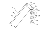
本発明のワイヤロープ絡まり防止構造を備えた移動式クレーン1は、図1に示すように、一般の道路や作業エリア内を走行するための車体10と、クレーン作業を行うためのクレーン装置20と、車体10の走行及びクレーン装置20によるクレーン作業の操作を行うためのキャブ30と、を備えている。クレーン装置20及びキャブ30は、車体10に対して水平方向に旋回可能な旋回台40に支持され、旋回台40の幅方向一方にクレーン装置20が配置され、幅方向他方にキャブ30が配置されている。
車体10は、前側及び後側の幅方向両側に設けられた車輪11と、前側の車輪11の前方及び後側の車輪11の後方に設けられたアウトリガ12と、を備えている。車体10は、エンジンの駆動力によって車輪11を回転させることで走行する。
クレーン装置20は、車体10に対して起伏自在に設けられると共に伸縮自在な伸縮ブーム21と、伸縮ブーム21に沿って延びると共に伸縮ブーム21の先端部から垂下されるワイヤロープ22と、ワイヤロープ22の巻き取り及び繰り出しを行うウインチ23と、伸縮ブーム21の先端部から垂下されるワイヤロープ22に吊り下げられるフックブロック24と、を有している。
伸縮ブーム21は、筒状に形成された複数のブーム部材21aからなり、最先端側を除くブーム部材21aの内部に、それぞれ先端側に隣り合うブーム部材21aが収納されている。伸縮ブーム21は、最先端側を除くブーム部材21aに対してそれぞれ先端側に隣り合うブーム部材21aが移動自在に構成され、図示しない油圧式の伸縮シリンダによって最基端側を除くブーム部材21aを移動させることにより伸縮動作を行う。また、最基端側のブーム部材21aは、基端部が旋回台40に上下方向に回動自在に連結されている。最基端側のブーム部材21aの伸長方向の略中央部と旋回台40との間には、図示しない油圧式の起伏シリンダが連結されており、起伏シリンダの伸縮動作によって伸縮ブーム21が起伏動作を行う。
また、最先端側のブーム部材21aの先端部には、ワイヤロープ22が垂下される所定位置としてのブームヘッド21bが設けられている。伸縮ブーム21の伸縮する方向を水平方向に向けた状態におけるブームヘッド21bの上側には、伸縮ブーム21の上面に沿って延びるワイヤロープ22を下方に向けて案内するためのガイドシーブ21cが設けられている。また、ブームヘッド21bの下側には、ブームヘッド21bとフックブロック24との間でワイヤロープ22を掛け回すためのトップシーブ21dが回転軸をブームヘッド21bの幅方向に向けて配置されている。
ワイヤロープ22は、硬鋼線を撚って構成した複数のストランドを、心綱を中心に撚り合わせたものである。ワイヤロープ22は、引張力が作用すると、撚り戻りが生じることにより、引張力が作用しない状態に対して捩じれが発生する。
ウインチ23は、軸方向の両端側にフランジが形成されたウインチドラム23aを有し、ウインチドラム23aにワイヤロープ22が巻き掛けられている。ウインチドラム23aは、旋回台40に回転自在に支持されており、図示しない油圧式のウインチモータによってワイヤロープ22の巻き取り動作及び繰り出し動作を行う。
フックブロック24は、図2に示すように、一対の側板24aと、一対の側板24aの下部に設けられたフック24bと、一対の側板24aの間に支軸を介して回転自在に支持されたフックシーブ24cと、を有している。
以上のように構成された移動式クレーン1では、ブームヘッド21bとフックブロック24との間におけるワイヤロープ22の巻き掛け方によって、ワイヤロープ22の巻き上げ速度に対するフックブロック24の移動速度、ワイヤロープ22の巻き上げ量に対するフックブロック24の移動量、フックブロック24及び吊荷を持ち上げるために必要なワイヤロープ22の引張力、が変化する。
例えば、図2に示すように、ガイドシーブ21cから下方に延びるワイヤロープ22を、フックシーブ24cで折り返して端部をブームヘッド21bに固定する2本掛けの状態では、ワイヤロープ22の巻き上げ速度に対するフックブロック24の移動速度、ワイヤロープ22の巻き上げ量に対するフックブロック24の移動量、フックブロック24及び吊荷を持ち上げるために必要なワイヤロープ22の引張力、がそれぞれ一本掛けの場合と比較して2分の1となる。
また、ガイドシーブ21cから下方に延びるワイヤロープ22を、フックシーブ24c、トップシーブ21dの順に折り返して端部をフックブロック24に固定する3本掛けの状態では、フックブロック24の移動速度及び移動量、ワイヤロープ22の引張力、がそれぞれ一本掛けの場合と比較して3分の1となる。
さらに、ガイドシーブ21cから下方に延びるワイヤロープ22を、フックシーブ24c、トップシーブ21d、フックシーブ24cの順に折り返して端部をブームヘッド21bに固定する4本掛けの状態では、フックブロック24の移動速度及び移動量、ワイヤロープ22の引張力、がそれぞれ一本掛けの場合と比較して4分の1となる。
このように、ブームヘッド21bとフックブロック24との間におけるワイヤロープ22の掛け数を多くすることによって、ワイヤロープ22の巻き上げ速度に対するフックブロック24の移動速度が小さくなり、ワイヤロープ22の巻き上げ量に対するフックブロック24の移動量が小さくなり、フックブロック24及び吊荷を持ち上げるために必要なワイヤロープ22の引張力が小さくなる。
また、ブームヘッド21bとフックブロック24との間におけるワイヤロープ22の掛け数が2本以上の状態において、ブームヘッド21bとフックブロック24との間に位置するワイヤロープ22には、図2に示すように、ブームヘッド21bとフックブロック24との間を上下方向に延びる部分である上下延伸部22aが互いに間隔をおいて複数構成される。
ワイヤロープ22の掛け数が2本以上の状態では、ワイヤロープ22の各上下延伸部22aに対してフックブロック24及び吊荷の重さが引張力として作用すると、各上下延伸部22aに撚り戻り生じて、複数の上下延伸部22a同士が絡み付く挙動が発生する場合がある。
そこで、ブームヘッド21bとフックブロック24との間に位置するワイヤロープ22には、図2に示すように、複数の上下延伸部22aの互いの間隔を保持することで、ワイヤロープ22の上下延伸部22a同士の絡み付きを防止するための間隔保持部材50が設けられている。
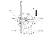
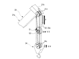
間隔保持部材50は、図2及び図3に示すように、フックブロック24を上下方向の一方に向かって移動させる際に、ワイヤロープ22が上下方向の一方に向かって移動する上下延伸部22aに接して転動する第1シーブ51と、ブームヘッド21bまたはフックブロック24に固定されたワイヤロープ22の端部を含む移動しない上下延伸部22aに接して転動する第2シーブ52と、を有している。
第1シーブ51は、図3に示すように、所定の第1ピッチ円直径D1を有している。第1シーブ51は、外周部の溝に接したワイヤロープ22を外側から押さえるための第1ワイヤ押さえローラ51aを有している。第1シーブ51は、第1ワイヤ押さえローラ51aによって、ワイヤロープ22に対してずれや滑りを生じることなく転動可能となっている。
第2シーブ52は、図3に示すように、第1ピッチ円直径D1よりも小さい第2ピッチ円直径D2を有している。第2シーブ52は、外周部の溝に接したワイヤロープ22を外側から押さえるための第2ワイヤ押さえローラ52aを有している。第2シーブ52は、第2ワイヤ押さえローラ52aによって、ワイヤロープ22に対してずれや滑りを生じることなく転動可能となっている。また、第2シーブ52は、回転軸が第1シーブ51の回転軸と軸方向に重なる位置で第1シーブ51に固定されており、第1シーブ51と共に回転するようになっている。
第1及び第2ワイヤ押さえローラ51a,52aは、第1シーブ51及び第2シーブ52の回転軸に回転自在に支持されたブラケット53に固定されている。
ブラケット53には、クレーン作業の際に使用される機器として、フックブロック24を上方から照らすライト53aが設けられている。
以上のように構成された移動式クレーン1のワイヤロープ絡まり防止構造において、ブームヘッド21bとフックブロック24との間におけるワイヤロープ22の掛け数が2本である場合の間隔保持部材50の動作を説明する。掛け数が2本の場合には、第2ピッチ円直径D2は、第1ピッチ円直径D1の2分の1となる。
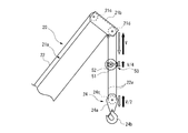
ウインチ23に巻き掛けられたワイヤロープ22の繰り出し又は巻き上げを所定の速度Vで行うと、フックブロック24は、図4に示すように、ワイヤロープ22の速度Vの2分の1の速度(V/2)で上下方向に移動する。
このとき、間隔保持部材50において、第1シーブ51は、ワイヤロープ22が上下方向に移動する一方の上下延伸部22aに接している。このため、第1シーブ51は、ワイヤロープ22の速度Vの速さの回転力を受ける。一方、第2シーブ52は、上端部がブームヘッド21bに固定された移動しない他方の上下延伸部22aに接している。このため、第2シーブ52は、第1シーブ51と共に回転し、他方の上下延伸部22aに沿って上下方向に移動する。ここで、第2シーブ52は、第1シーブ51と同一の角速度で回転する。このため、仮に、第2ピッチ円直径D2が第1シーブ51の第1ピッチ円直径D1と同一の場合に、第1シーブ51及び第2シーブ52は、ワイヤロープ22の速度Vの2分の1の速度(V/2)で他方の上下延伸部22aに沿って移動する。しかし、第2シーブ52の第2ピッチ円直径D2は、第1シーブ51の第1ピッチ円直径D1の2分の1であるため、間隔保持部材50は、図4に示すように、ワイヤロープ22の速度Vの4分の1の速度(V/4)で他方の上下延伸部22aに沿って移動する。即ち、間隔保持部材50は、フックブロック24の上下方向に移動する速度(V/2)の2分の1の速度(V/4)で上下方向に移動する。これにより、間隔保持部材50は、フックブロック24が上下方向に移動する際に、ブームヘッド21bとフックブロック24との中間部に常に位置することとなる。したがって、間隔保持部材50は、ブームヘッド21bとフックブロック24との間の距離にかかわらず、複数の上下延伸部22aの上下方向の中間部において互いの間隔を保持するため、複数の上下延伸部22a同士の絡み付きの発生が抑制される。
このように、本実施形態のワイヤロープ絡まり防止構造によれば、ワイヤロープ22の複数の上下延伸部22aの間隔を保持するための間隔保持部材50を備え、間隔保持部材50が、ブームヘッド21bとフックブロック24との間隔の変化に応じて、ブームヘッド21bとフックブロック24との間を上下方向に移動する。
これにより、複数の上下延伸部22aの上下方向の中間部の互いの間隔を間隔保持部材50によって保持することで、複数の上下延伸部22aの上下方向にわたって互いの間隔を保持することができるので、荷物を吊り下げたフックブロック24とブームヘッド21bとの間隔が大きい場合においても、複数の上下延伸部22aが互いに絡み付くことを防止することが可能となる。
また、間隔保持部材50は、フックブロック24を上下方向の一方に移動させる際に、ワイヤロープ22が上下方向の一方に向かって移動する上下延伸部22aに接して転動する第1シーブ51と、フックブロック24を上下方向の一方に移動させる際に、ワイヤロープ22が移動しない上下延伸部22aに接して転動する第2シーブ52と、を有し、第1シーブ51及び第2シーブ52を互いに連動させることで、ブームヘッド21bとフックブロック24との間を上下方向に移動する。
これにより、ウインチ23によるワイヤロープ22の繰り出し動作及び巻き上げ動作に連動させて間隔保持部材50を移動させることができるので、専用の動力源を必要とすることなく間隔保持部材50を移動させることができ、製造コスト及び重量の低減を図ることが可能となる。
また、第1シーブ51及び第2シーブ52は、互いに異なる第1ピッチ円直径D1及び第2ピッチ円直径D2を有し、それぞれの回転中心が軸方向に重なる位置で互いに固定されることで連動する。
これにより、間隔保持部材50を移動させる機構を簡単な構成とすることができるので、製造コスト及び重量の低減を図ることが可能となる。
また、間隔保持部材50は、上下方向に移動するフックブロック24とブームヘッド21bとの中間部に位置する。
これにより、絡み付きが生じやすいフックブロック24とブームヘッド21bとの中間部に位置する複数の上下延伸部22aの互いの間隔を保持することができるので、ワイヤロープ22の絡み付きを確実に防止することが可能となる。
また、間隔保持部材50には、フックブロック24を上方から照らすライト53aが取り付けられている。
これにより、クレーン作業の際に使用される機器を、専用の部材を必要とすることなく、ブームヘッド21bとフックブロック24との間に設置することが可能となるので、設置コストを抑えて、クレーン作業時の安全性及び作業効率を向上させることが可能となる。
図5及び図6は、本発明の第2実施形態を示すものである。尚、前記実施形態と同様の構成部分には同一の符号を付して示す。
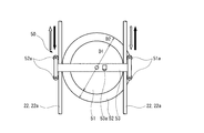
本実施形態の間隔保持部材50は、図5及び図6に示すように、ワイヤロープ22の掛け数を4本以上に設定した場合に、第1シーブ51を、ワイヤロープ22がフックブロック24の移動する方向に向かって移動する上下延伸部22aに当接させ、第2シーブ52を、ワイヤロープ22の移動する方向と反対の方向に向かって移動する上下延伸部22aに当接させている。
以上のように構成された移動式クレーン1のワイヤロープ絡まり防止構造において、ワイヤロープ22の掛け数が4本の場合における間隔保持部材50の動作を説明する。ワイヤロープ22の掛け数が4本の場合には、第2シーブ52の第2ピッチ円直径D2は、第1ピッチ円直径D1の3分の5となる。
ウインチ23に巻き掛けられたワイヤロープ22の繰り出し又は巻き上げを所定の速度Vで行うと、4本掛けでワイヤロープ22に吊り下げられたフックブロック24は、図6に示すように、ワイヤロープ22の速度Vの4分の1の速度(V/4)で上下方向に移動する。
このとき、間隔保持部材50において、第1シーブ51は、フックブロック24が移動する方向に移動する上下延伸部22aに接している。このため、第1シーブ51は、ワイヤロープ22の速度Vの速さの回転力を受ける。一方、第2シーブ52は、フックブロック24が移動する方向と反対の方向に移動する上下延伸部22aに接している。このため、第2シーブ52は、第1シーブ51が受ける回転方向と反対方向に、ワイヤロープ22の速度Vの速さの回転力を受ける。ここで、第2シーブ52は、第1シーブ51と一体に構成され、第1シーブ51と同一の角速度で回転する。このため、仮に、第2ピッチ円直径D2が第1シーブ51の第1ピッチ円直径D1と同一の場合に、第1シーブ51及び第2シーブ52は、第1シーブ51が接する上下延伸部22aと第2シーブが接する上下延伸部22aとの間で上下方向に移動することなく回転する。しかし、第2シーブ52の第2ピッチ円直径D2は、第1シーブ51の第1ピッチ円直径D1の3分の5であるため、第1シーブ51に対して周長が大きい第2シーブ52がワイヤロープ22に接しながら転動する方向に間隔保持部材50が移動する。これにより、間隔保持部材50は、フックブロック24が移動する方向に向かってワイヤロープ22の速度Vの8分の1の速度(V/8)で移動する。即ち、間隔保持部材50は、フックブロック24の上下方向に移動する速度(V/4)の2分の1の速度(V/8)で上下方向に移動する。これにより、間隔保持部材50は、フックブロック24が上下方向に移動する際に、ブームヘッド21bとフックブロック24との中間部に常に位置することとなる。したがって、間隔保持部材50は、ブームヘッド21bとフックブロック24との間の距離にかかわらず、複数の上下延伸部22aの上下方向の中間部において互いの間隔を保持するため、複数の上下延伸部22a同士の絡み付きの発生が抑制される。
このように、本実施形態のワイヤロープ絡まり防止構造によれば、前記実施形態と同様に、複数の上下延伸部22aの上下方向の中間部の互いの間隔を間隔保持部材50によって保持することで、複数の上下延伸部22aの上下方向にわたって互いの間隔を保持することができるので、荷物を吊り下げたフックブロック24とブームヘッド21bとの間隔が大きい場合においても、複数の上下延伸部22aが互いに絡み付くことを防止することが可能となる。
また、間隔保持部材50は、フックブロック24を上下方向の一方に移動させる際に、ワイヤロープ22が上下方向の一方に向かって移動する上下延伸部22aに接して転動する第1シーブ51と、フックブロック24を上下方向の一方に移動させる際に、上下方向の他方に向かってワイヤロープ22が移動する上下延伸部22aに接して転動する第2シーブ52と、を有し、第1シーブ51及び第2シーブ52を互いに連動させることで、ブームヘッド21bとフックブロック24との間を上下方向に移動する。
これにより、ウインチ23によるワイヤロープ22の繰り出し動作及び巻き上げ動作に連動させて間隔保持部材50を移動させることができるので、専用の動力源を必要とすることなく間隔保持部材50を移動させることができ、製造コストの低減を図ることが可能となる。
尚、前記実施形態では、移動式クレーン1のクレーン装置20を示したが、2本掛け以上の掛け数でフックブロックを吊り下げる構造を有するものであれば、タワークレーンに本発明を適用してもよいし、ブームを有していない天井クレーンや門型クレーン等に本発明を適用してもよい。
また、前記実施形態では、クレーン作業の際に使用される機器として、フックブロック24を上方から照らすライト53aを間隔保持部材50に設けたものを示したが、これに限られるものではない。例えば、間隔保持部材50には、フックを上方から監視するためのカメラや、フックブロック24と伸縮ブーム21との間で無線通信を行う際に用いる中継器等を取り付けることが可能である。
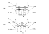
また、前記実施形態では、第1シーブ51及び第2シーブ52の回転軸同士を固定することにより第1シーブ51及び第2シーブ52を互いに連動させるようにしたものを示したが、これに限られるものではない。例えば、第1シーブ51と第2シーブ52を、図7(a)に示すベルト54aとプーリ54bや、図7(b)に示す歯車54cの組み合わせ等からなる動力伝達部材54によって回転数を変換して連動させることで、前記実施形態と同様に、ブームヘッド21bとフックブロック24との間の所定位置に間隔保持部材50を位置させることが可能となる。
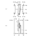
また、前記第2実施形態では、ワイヤロープ22の掛け数を4本とした場合において、4本のワイヤロープ22のうちの2本のワイヤロープ22に対して間隔保持部材50を取り付けるようにしたものを示したが、これに限られるものではない。掛け数が3本以上の場合において、上下延伸部22aのそれぞれの間に間隔保持部材50を取り付けるようにすることで、より確実に上下延伸部22aの絡み付きを防止することができる。図8では、掛け数が6本の場合において、対向する上下延伸部22a毎に間隔保持部材50を取り付けたものを示している。
また、前記第2実施形態では、ワイヤロープ22の掛け数を4本とした場合において、4本のワイヤロープ22のうちの2本のワイヤロープ22に対して間隔保持部材50を取り付けるようにしたものを示したが、これに限られるものではない。掛け数が3本以上の場合において、図9に示すように、間隔保持部材50が取り付けられていない上下延伸部22aを、間隔保持部材50のブラケット53から延びるローラ支持部材55の端部に回転自在に設けたガイドローラ55aによって案内することで、より確実にワイヤロープ22の絡み付きを防止することができる。
また、前記実施形態では、間隔保持部材50を、フックブロック24が上下方向に移動する際に、ブームヘッド21bとフックブロック24との中間部に常に位置させるようにしたものを示したが、これに限られるものではない。例えば、間隔保持部材を、ブームヘッド21bとフックブロック24との間における、ブームヘッド21bから3分の1の部分に常に位置させるようにしてもよい。この場合には、第1シーブ51及び第2シーブ52のそれぞれのピッチ円直径または回転数を調整して、間隔保持部材50の移動速度を設定すればよい。
また、前記実施形態では、間隔保持部材50の第1シーブ51及び第2シーブ52がワイヤロープ22に対してずれや滑りを生じることなく転動するものを示したが、第1シーブ51及び第2シーブ52がワイヤロープ22に対して僅かにずれや滑りが生じたとしても前述の効果を奏する。間隔保持部材50は、第1シーブ51及び第2シーブ52がワイヤロープ22に対してずれや滑りが生じた場合に、ずれや滑りを修正して元に戻す手段を備えることが好ましい。
20…クレーン装置、21b…ブームヘッド、21d…トップシーブ、22…ワイヤロープ、22a…上下延伸部、23…ウインチ、24…フックブロック、24c…フックシーブ、50…間隔保持部材、51…第1シーブ、52…第2シーブ、53a…ライト、54…動力伝達部材。
Claims (6)
- ウインチと、ウインチに巻き掛けられて先端側が所定位置から垂下されるワイヤロープと、ワイヤロープに吊り下げられるフックブロックと、所定位置側及びフックブロック側の少なくともフックブロック側に設けられ、所定位置側及びフックブロック側の一方から他方に向かって延びるワイヤロープを他方から一方に向かって延びるように向きを変えるシーブと、を備え、所定位置から垂下されたワイヤロープをシーブに掛け回すとともに、ワイヤロープの端部を所定位置側またはフックブロック側に固定し、ウインチによるワイヤロープの繰り出し動作及び巻き上げ動作を行うことでフックブロックを上下方向に移動させるクレーン装置において、
所定位置とフックブロックとの間に位置するワイヤロープにおける上下方向に延びる部分である複数の上下延伸部の互いの間隔を保持する間隔保持部材を備え、
間隔保持部材は、所定位置とフックブロックとの間隔の変化に応じて、所定位置とフックブロックとの間を上下方向に移動する
ことを特徴とするクレーン装置のワイヤロープ絡まり防止構造。 - 間隔保持部材は、
フックブロックを上下方向の一方に移動させる際に、ワイヤロープが上下方向の一方に向かって移動する上下延伸部に接して転動する第1シーブと、
フックブロックを上下方向の一方に移動させる際に、上下方向の他方に向かってワイヤロープが移動する上下延伸部、または、ワイヤロープが移動しない上下延伸部に接して転動する第2シーブと、を有し、
第1シーブ及び第2シーブを互いに連動させることで、所定位置とフックブロックとの間を上下方向に移動する
ことを特徴とする請求項1に記載のクレーン装置のワイヤロープ絡まり防止構造。 - 第1シーブ及び第2シーブは、互いに異なる径方向寸法を有し、それぞれの回転中心が軸方向に重なる位置で互いに固定されることで連動する
ことを特徴とする請求項2に記載のクレーン装置のワイヤロープ絡まり防止構造。 - 第1シーブ及び第2シーブは、動力伝達部材を介して互いが連結されることで連動する
ことを特徴とする請求項2に記載のクレーン装置のワイヤロープ絡まり防止構造。 - 間隔保持部材は、上下方向に移動するフックブロックと所定位置との中間部に位置する
ことを特徴とする請求項1乃至3のいずれかに記載のクレーン装置のワイヤロープ絡まり防止構造。 - 間隔保持部材には、クレーン装置による作業の際に使用される機器が取り付けられている
ことを特徴とする請求項1乃至5のいずれかに記載のクレーン装置のワイヤロープ絡まり防止構造。
Applications Claiming Priority (2)
| Application Number | Priority Date | Filing Date | Title |
|---|---|---|---|
| JP2016-036888 | 2016-02-29 | ||
| JP2016036888A JP6339611B2 (ja) | 2016-02-29 | 2016-02-29 | クレーン装置のワイヤロープ絡まり防止構造 |
Publications (1)
| Publication Number | Publication Date |
|---|---|
| WO2017149847A1 true WO2017149847A1 (ja) | 2017-09-08 |
Family
ID=59743692
Family Applications (1)
| Application Number | Title | Priority Date | Filing Date |
|---|---|---|---|
| PCT/JP2016/083835 Ceased WO2017149847A1 (ja) | 2016-02-29 | 2016-11-15 | クレーン装置のワイヤロープ絡まり防止構造 |
Country Status (2)
| Country | Link |
|---|---|
| JP (1) | JP6339611B2 (ja) |
| WO (1) | WO2017149847A1 (ja) |
Cited By (1)
| Publication number | Priority date | Publication date | Assignee | Title |
|---|---|---|---|---|
| CN110654975A (zh) * | 2019-11-11 | 2020-01-07 | 中昇建机(南京)重工有限公司 | 一种塔机主吊钢丝绳防打搅吊具 |
Citations (6)
| Publication number | Priority date | Publication date | Assignee | Title |
|---|---|---|---|---|
| JPS4822739B1 (ja) * | 1970-07-21 | 1973-07-09 | ||
| JPH056320Y2 (ja) * | 1989-05-24 | 1993-02-18 | ||
| JPH0530082U (ja) * | 1991-09-25 | 1993-04-20 | 新明和工業株式会社 | フツク格納式クレーンにおけるワイヤ絡み解消装置 |
| JP2556243Y2 (ja) * | 1992-06-26 | 1997-12-03 | 本田技研工業株式会社 | クレーン装置 |
| JP4511858B2 (ja) * | 2004-03-26 | 2010-07-28 | ポリマテック株式会社 | 相変化熱伝導性成形体 |
| GB2519997A (en) * | 2013-11-05 | 2015-05-13 | Technip France | Multi-cable subsea lifting system |
-
2016
- 2016-02-29 JP JP2016036888A patent/JP6339611B2/ja active Active
- 2016-11-15 WO PCT/JP2016/083835 patent/WO2017149847A1/ja not_active Ceased
Patent Citations (6)
| Publication number | Priority date | Publication date | Assignee | Title |
|---|---|---|---|---|
| JPS4822739B1 (ja) * | 1970-07-21 | 1973-07-09 | ||
| JPH056320Y2 (ja) * | 1989-05-24 | 1993-02-18 | ||
| JPH0530082U (ja) * | 1991-09-25 | 1993-04-20 | 新明和工業株式会社 | フツク格納式クレーンにおけるワイヤ絡み解消装置 |
| JP2556243Y2 (ja) * | 1992-06-26 | 1997-12-03 | 本田技研工業株式会社 | クレーン装置 |
| JP4511858B2 (ja) * | 2004-03-26 | 2010-07-28 | ポリマテック株式会社 | 相変化熱伝導性成形体 |
| GB2519997A (en) * | 2013-11-05 | 2015-05-13 | Technip France | Multi-cable subsea lifting system |
Cited By (1)
| Publication number | Priority date | Publication date | Assignee | Title |
|---|---|---|---|---|
| CN110654975A (zh) * | 2019-11-11 | 2020-01-07 | 中昇建机(南京)重工有限公司 | 一种塔机主吊钢丝绳防打搅吊具 |
Also Published As
| Publication number | Publication date |
|---|---|
| JP2017154827A (ja) | 2017-09-07 |
| JP6339611B2 (ja) | 2018-06-06 |
Similar Documents
| Publication | Publication Date | Title |
|---|---|---|
| CN102471042B (zh) | 移动式起重机 | |
| JP7362739B2 (ja) | ロープガイド装置、電動巻上機及びクレーンシステム | |
| RU2590791C2 (ru) | Приводной агрегат для как минимум одного тягового средства | |
| JP6339611B2 (ja) | クレーン装置のワイヤロープ絡まり防止構造 | |
| CN110155894A (zh) | 一种伺服式排绳机构 | |
| CN113800419B (zh) | 一种正交导向式起重绞盘装置 | |
| KR200464796Y1 (ko) | 무대구동장치 | |
| WO2012167504A1 (zh) | 挡绳装置及具有其的工程机械 | |
| CN204802900U (zh) | 一种动臂式塔机的变幅机构 | |
| JP2012020820A (ja) | エレベータ | |
| JP5600533B2 (ja) | クレーン用フック装置 | |
| WO2007020705A1 (ja) | 転向滑車装置 | |
| JP5385601B2 (ja) | クレーン | |
| JP2004137072A (ja) | トロリクレーン | |
| KR102368663B1 (ko) | 크레인용 와이어 가이딩 장치 | |
| CN210286572U (zh) | 一种伺服式排绳机构 | |
| CN101973494A (zh) | 一种起重机起升机构的排绳装置 | |
| CN107758529A (zh) | 起重臂与起重装置 | |
| CN223879360U (zh) | 一种起重机钢丝绳防乱绳装置 | |
| JP5031558B2 (ja) | エレベータ装置 | |
| JPH06166492A (ja) | ホイスト装置 | |
| JP2000297527A (ja) | 塔状構造物内部の清掃保全作業用ゴンドラ装置 | |
| CN214399573U (zh) | 一种起重机械用钢丝绳卷取装置 | |
| JP2014037302A (ja) | エレベーター | |
| KR20150098331A (ko) | 선박 엔진룸용 호이스트장치 |
Legal Events
| Date | Code | Title | Description |
|---|---|---|---|
| NENP | Non-entry into the national phase |
Ref country code: DE |
|
| 121 | Ep: the epo has been informed by wipo that ep was designated in this application |
Ref document number: 16892683 Country of ref document: EP Kind code of ref document: A1 |
|
| 122 | Ep: pct application non-entry in european phase |
Ref document number: 16892683 Country of ref document: EP Kind code of ref document: A1 |