WO2017149610A1 - 吸収性物品に係る資材供給装置、及び資材供給方法 - Google Patents
吸収性物品に係る資材供給装置、及び資材供給方法 Download PDFInfo
- Publication number
- WO2017149610A1 WO2017149610A1 PCT/JP2016/056098 JP2016056098W WO2017149610A1 WO 2017149610 A1 WO2017149610 A1 WO 2017149610A1 JP 2016056098 W JP2016056098 W JP 2016056098W WO 2017149610 A1 WO2017149610 A1 WO 2017149610A1
- Authority
- WO
- WIPO (PCT)
- Prior art keywords
- succeeding
- coil
- absorbent article
- loop
- preceding material
- Prior art date
Links
Images


Classifications
-
- A—HUMAN NECESSITIES
- A61—MEDICAL OR VETERINARY SCIENCE; HYGIENE
- A61F—FILTERS IMPLANTABLE INTO BLOOD VESSELS; PROSTHESES; DEVICES PROVIDING PATENCY TO, OR PREVENTING COLLAPSING OF, TUBULAR STRUCTURES OF THE BODY, e.g. STENTS; ORTHOPAEDIC, NURSING OR CONTRACEPTIVE DEVICES; FOMENTATION; TREATMENT OR PROTECTION OF EYES OR EARS; BANDAGES, DRESSINGS OR ABSORBENT PADS; FIRST-AID KITS
- A61F13/00—Bandages or dressings; Absorbent pads
- A61F13/15—Absorbent pads, e.g. sanitary towels, swabs or tampons for external or internal application to the body; Supporting or fastening means therefor; Tampon applicators
- A61F13/45—Absorbent pads, e.g. sanitary towels, swabs or tampons for external or internal application to the body; Supporting or fastening means therefor; Tampon applicators characterised by the shape
- A61F13/49—Absorbent articles specially adapted to be worn around the waist, e.g. diapers
-
- B—PERFORMING OPERATIONS; TRANSPORTING
- B65—CONVEYING; PACKING; STORING; HANDLING THIN OR FILAMENTARY MATERIAL
- B65H—HANDLING THIN OR FILAMENTARY MATERIAL, e.g. SHEETS, WEBS, CABLES
- B65H19/00—Changing the web roll
- B65H19/10—Changing the web roll in unwinding mechanisms or in connection with unwinding operations
- B65H19/14—Accumulating surplus web for advancing to machine while changing the web roll
Definitions
- the present invention relates to a material supply device and a material supply method related to absorbent articles such as disposable diapers.
- the various materials 3 which concern on the diaper 1 are each carried in the form of the material coil 3C coiled up.
- the material splicing device 20 ′ joins the material 3f of the material coil 3Cf that has not been fed out to the material 3a.
- the material 3 is continuously supplied to the processing apparatus 110 ′ of the production line without interruption.
- the material splicing device 20 has two rotating shafts 24a' and 24f 'that can be driven and rotated while supporting the material coil 3C. Then, when one rotating shaft 24a ′ is driven to rotate, the material 3a (3) is fed out as the preceding material 3a from the material coil 3Ca, and when the material 3a of this material coil 3Ca is almost gone, the other rotation The shaft 24f ′ starts driving rotation, and thereby rotates the unrolled material coil 3Cf supported by the rotating shaft 24f ′.
- the preceding material 3a fed from the feeding material coil 3Ca to the outer peripheral surface 3Cfs during rotation of the undrawn material coil 3Cf by the pressing member 40 ′ the preceding material
- the material 3f (3) on the outer peripheral surface 3Cfs of the uncoiled material coil 3Cf is joined to 3a as the subsequent material 3f.
- the material 3 is continuously supplied to the processing apparatus 110 ′ on the production line without interruption and without stopping the feeding operation.
- FIG. 1B (as viewed from the arrow BB in FIG. 1A)
- the conveying direction of the material 3 in the various processing devices 110 ′, 110 ′ is changed to the conveyance direction of the material 3 in the processing device 110' by a turn bar 50 'as a conveyance direction changing member.
- the turn bar 50 ′ the meandering of the material 3 is likely to occur when the tension of the material 3 varies due to the change in the transport direction. And when such meandering is large, a line trouble may be caused.
- the tension of the material 3f can fluctuate greatly when the first turn (first turn) of the outer periphery of the material coil 3Cf that is not advanced in FIG. That is, immediately after joining the material 3f of the subsequent material coil 3Cf that has not been advanced to the preceding material 3a that is being advanced, the material 3f of the material coil 3Cf that has not been advanced is included in the material 3a that is being advanced.
- the tension of the material 3 since the material coil 3Cf on the downstream side of the undrawn state is almost in tension before joining, the tension of the material 3 generally decreases immediately after joining. Can vary greatly.
- a storage device 40 ′ capable of storing the material 3 in the form of a loop 3L is provided between the material splicing device 20 ′ and the turn bar 50 ′. It is conceivable to control the rotational speed (rpm) of the rotary shaft 24 'of the material splicing device 20' so that the size of the loop 3L is constant.
- the present invention has been made in view of the conventional problems as described above, and its purpose is to immediately suppress the fluctuation in the tension of the material fed out from the material coil, so that the conveyance direction changing member such as a turn bar can be obtained.
- the main invention for achieving the above object is: By joining the material of another material coil as the succeeding material to the preceding material that is continuously fed out from the material coil, processing the succeeding material on the absorbent article continuously with the preceding material
- a material splicing device that joins the succeeding material to the preceding material by pressing toward the outer peripheral surface of the coil;
- a storage device capable of storing the preceding material or the succeeding material continuously sent from the material splicing device in the form of a loop;
- the preceding material or the subsequent material sent from the storage device with the first direction as the transport direction is changed to a second direction that intersects the first direction in plan view and sent to the processing device.
- a conveyance direction changing member At least after joining the succeeding material to the preceding material, the driving rotation operation of the other rotating shaft is controlled so that the size of the loop is constant,
- the length of the transport path of the preceding material or the succeeding material from the joining position where the succeeding material is joined to the preceding material to the reaching position reaching the accumulating device is the accumulation device. Characterized in that it is shorter than the length of the transport path of the preceding material or the succeeding material from the delivery position sent to the transport direction changing member to the arrival position reaching the transport direction changing member. It is the material supply apparatus which concerns on the absorbent article which does.
- a material supply method for supplying to an apparatus The following material that rotates the preceding material fed from the preceding material coil supported by one rotating shaft that is driven to rotate by the driving rotation operation of the other rotating shaft that supports the following material coil.
- the material splicing device joins the subsequent material to the preceding material by pressing it toward the outer peripheral surface of the coil;
- the storage device stores the preceding material or the subsequent material continuously sent from the material splicing device in the form of a loop;
- the transport direction changing member changes the transport direction to the second direction intersecting the first direction in plan view with respect to the preceding material or the subsequent material sent from the storage device with the first direction as the transport direction.
- the driving rotation operation of the other rotating shaft is controlled so that the size of the loop is constant
- the length of the transport path of the preceding material or the succeeding material from the joining position where the succeeding material is joined to the preceding material to the reaching position reaching the accumulating device is the accumulation device. Characterized in that it is shorter than the length of the transport path of the preceding material or the succeeding material from the delivery position sent to the transport direction changing member to the arrival position reaching the transport direction changing member.
- the present invention it is possible to prevent the meandering of the material at the conveying direction changing member such as a turn bar by immediately suppressing the tension fluctuation of the material fed out from the material coil.
- FIG. 1A is a schematic side view of an example of the material splicing device 20 '
- FIG. 1B is a view taken along the line BB in FIG. 1A.
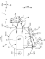
- It is a schematic side view of the storage device 40 'provided between the material splicing device 20' and the turn bar 50 '.
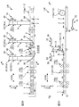
- FIG. 3A is a schematic side view of a production line LM for a disposable diaper 1 as an example of an absorbent article
- FIG. 3B is a schematic plan view of the line LM indicated by arrows BB in FIG. 3A. It is IV-IV arrow line view in FIG. 3B.
- FIG. 4B is a schematic plan view taken along line BB in FIG. 4A.
- FIG. 6 is a schematic side view of an example in which a member first contacted by a material 3f (3) fed out from a subsequent material coil 3Cf is an upstream fixed position roll 41u included in the storage device 40.
- a material splicing device that joins the succeeding material to the preceding material by pressing toward the outer peripheral surface of the coil;
- a storage device capable of storing the preceding material or the succeeding material continuously sent from the material splicing device in the form of a loop;
- the preceding material or the subsequent material sent from the storage device with the first direction as the transport direction is changed to a second direction that intersects the first direction in plan view and sent to the processing device.
- a conveyance direction changing member At least after joining the succeeding material to the preceding material, the driving rotation operation of the other rotating shaft is controlled so that the size of the loop is constant,
- the length of the transport path of the preceding material or the succeeding material from the joining position where the succeeding material is joined to the preceding material to the reaching position reaching the accumulating device is the accumulation device. Characterized in that it is shorter than the length of the transport path of the preceding material or the succeeding material from the delivery position sent to the transport direction changing member to the arrival position reaching the transport direction changing member. It is the material supply apparatus which concerns on the absorbent article which does.
- the storage device is positioned closer to the material splicing device than the midpoint position between the transport direction changing member and the material splicing device in the material transport path. . Therefore, it is possible to immediately suppress fluctuations in tension as compared with the case where the storage device is positioned closer to the conveyance direction changing member. As a result, it is possible to send the material to the transport direction changing member while suppressing fluctuations in tension, thereby effectively preventing the meandering of the material at the transport direction changing member. .
- a material supply device for such an absorbent article The length of the transport path of the preceding material or the succeeding material between the arrival position and the delivery position of the storage device is greater than the peripheral length of the outer material surface of the succeeding material coil in an unpaid state. Short is desirable.
- the subsequent material coil is eccentric or deformed in the radial direction, so that the subsequent material coil is rotated every 360 °.
- the length of the conveyance path from the arrival position to the delivery position of the storage device generally corresponds to the entire length of the loop, but it is assumed that the entire length of the loop is after the undrawn state.
- the tension fluctuation for the second round of the material coil of the subsequent row can coexist in the loop, If it does so, it will become difficult to suppress the tension
- the total length of the loop is shorter than the peripheral length of the outer peripheral surface. Can be substantially suppressed. As a result, the tension fluctuation can be reliably suppressed. Further, since the entire length of the loop can be shortened, the influence of the material elongation or the like can be further reduced, and as a result, the tension fluctuation of the material can be reliably suppressed.
- a material supply device for such an absorbent article The length of the transport path of the preceding material or the succeeding material between the joining position and the delivery position is preferably shorter than the circumferential length of the outer peripheral surface of the succeeding material coil in an undrawn state. .
- the length of the transport path of the preceding material or the succeeding material from the joining position to the delivery position is the following in the undrawn state. Shorter than the circumference of the outer peripheral surface of the material coil. Therefore, the tension fluctuation of the first round can be reliably suppressed before the input of the tension fluctuation of the second round to the loop, and as a result, the tension fluctuation can be more reliably suppressed. Further, since the entire length of the loop can be shortened, the influence of the material elongation and the like can be further reduced, and as a result, the tension fluctuation of the material can be more reliably suppressed.
- the storage device has a pair of fixed-position rolls that are rotatably supported at fixed positions, and a moving roll that is guided so as to reciprocate in a direction in which the size of the loop can be changed,
- the loop is formed by hanging the preceding material or the succeeding material on the moving roll between the pair of fixed position rolls,
- the storage device preferably has only one moving roll.
- the storage device is provided with only one moving roll. Therefore, compared with the case where there are a plurality of moving rolls, it is possible to suppress the tension of the material from fluctuating due to the inertia of the moving roll itself when the moving roll reciprocates. As a result, the storage device can more reliably suppress fluctuations in material tension.
- a material supply device for such an absorbent article After joining to the preceding material, the member with which the succeeding material fed out from the succeeding material coil first comes into contact is located upstream of the pair of fixed-position rolls in the transport direction. A fixed position roll is desirable.
- the problem caused by the presence of a transport roll in the transport path from the subsequent material coil to the storage device after the subsequent material is fed from the subsequent material coil It can be quickly avoided that the transport roll comes into contact with the material and the tension of the material is fluctuated due to inertia such as rotation of the transport roll.
- the storage device can suppress fluctuations in the tension of subsequent materials without any major problem.
- a material supply device for such an absorbent article Each time when the size of the loop becomes maximum and minimum in the operation of feeding the succeeding material from the succeeding material coil, the starting point is the time when the succeeding material is joined to the preceding material. It is desirable that it is included until the other rotation shaft makes one rotation.
- the size of the loop is maximized and minimized when the succeeding material coil is fed out in the first round. Therefore, if the operator monitors the loop of the storage device only for the time corresponding to the first turn of the subsequent material coil, it is not necessary to monitor the loop thereafter. Can reduce the burden of monitoring work.
- a material supply method for supplying to an apparatus The following material that rotates the preceding material fed from the preceding material coil supported by one rotating shaft that is driven to rotate by the driving rotation operation of the other rotating shaft that supports the following material coil.
- the material splicing device joins the subsequent material to the preceding material by pressing it toward the outer peripheral surface of the coil;
- the storage device stores the preceding material or the subsequent material continuously sent from the material splicing device in the form of a loop;
- the transport direction changing member changes the transport direction to the second direction intersecting the first direction in plan view with respect to the preceding material or the subsequent material sent from the storage device with the first direction as the transport direction.
- the driving rotation operation of the other rotating shaft is controlled so that the size of the loop is constant
- the length of the transport path of the preceding material or the succeeding material from the joining position where the succeeding material is joined to the preceding material to the reaching position reaching the accumulating device is the accumulation device. Characterized in that it is shorter than the length of the transport path of the preceding material or the succeeding material from the delivery position sent to the transport direction changing member to the arrival position reaching the transport direction changing member.
- FIG. 3A is a schematic side view of an absorbent article production line LM
- FIG. 3B is a schematic plan view of the line LM indicated by arrows BB in FIG. 3A.
- a disposable diaper 1 is produced as an example of an absorbent article.
- a soft and flexible continuous sheet 3 such as a nonwoven fabric or a film is used. The materials 3, 3...
- each material 3 is brought into the production line LM in the form of a material coil 3C formed by winding the continuous sheet 3 as a material around the paper tube 3p (FIG. 4A) in a coil shape. Then, the various material coils 3C, 3C... Are mounted on the material supply device 10 provided in the production line LM for each type of the material 3, and each material 3 is fed out. Each material 3 is subjected to processing such as pressing and cutting by various processing units 110, 110 (corresponding to a processing device) while being transported along a predetermined transport path in the production line LM. The disposable diaper 1 is finally manufactured by being polymerized with other materials 3 and appropriate members 2.
- Examples of the processing unit 110 include a fiber stacking device 110a, a cutting device 110b, a pressing device 110c, a leg hole cutting device 110d, and an end cutting device 110e, but are not limited thereto.
- each apparatus 110a, 110b, 110c, 110d, 110e has the following functions, for example.
- the fiber stacking device 110a generates the absorbent body 2 as the above-mentioned member using, as a main material, liquid absorbent fibers such as pulp fibers.
- the cutting device 110b cuts the material 3 into a single sheet to generate a leakage preventing sheet 3s, and conveys the leakage preventing sheets 3s, 3s adjacent to each other in the conveying direction with a gap therebetween.
- seat 3s is joined to another material 3 in the state which opened this space
- a known slip cutting device for example, Japanese Patent Application Laid-Open No. 2011-083547
- the pressing device 110c presses the materials 3, 3... With a pair of upper and lower rolls.
- the leg hole cutting device 110d forms leg openings in the materials 3, 3... By a pair of upper and lower rolls.
- the end cut device 110e generates the same diaper 1 by separating the diaper 1 from the materials 3, 3.
- X direction three directions orthogonal to each other in the production line LM are referred to as an X direction, a Y direction, and a Z direction, respectively.
- the X direction and the Y direction are each oriented in the horizontal direction, but as shown in FIG. 3A, the Z direction is oriented in the vertical direction.
- the X direction and the Y direction are orthogonal to each other.
- the X direction corresponds to the “second direction” according to the claims
- the Y direction corresponds to the “first direction” according to the claims.
- various processing units 110, 110,... are arranged side by side along the X direction.
- the material 3 is transported along the X direction in plan view between the processing units 110, 110.
- each material supply device 10 is moved from the processing units 110, 110. It is arranged at a shifted position. Therefore, the supply of the material 3 from each material supply apparatus 10 to the processing units 110, 110... Is mainly performed along the Y direction. That is, after the material 3 fed out in the Y direction in the material supply apparatus 10 is transported along the Y direction, the processing unit 110, 110 is supplied with the material 3.
- the material supply device 10 is provided corresponding to each type of the material 3, but the basic configuration of each material supply device 10, 10... Is the same. Therefore, below, the one material supply apparatus 10 is demonstrated.
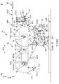
- FIG. 4A is a view taken along arrow IV-IV in FIG. 3B.
- FIG. 4B is a schematic plan view taken along the line BB in FIG. 4A. 4A and 4B, the members are appropriately omitted for the purpose of preventing the complication of the drawings.
- the material supply device 10 has a material splicing device 20.
- the material splicing device 20 then transfers the material 3f of another material coil 3Cf that has not been fed out to the material 3f subsequent to the material 3a before there is no preceding material 3a being fed out from the material coil 3Ca.
- the material 3 (3a, 3f) is continuously supplied to the processing unit 110 of the production line LM without interruption.
- a storage device 40 for storing the material 3 (3a, 3f) sent from the material splicing device 20 in the form of a loop 3L is provided at a position downstream of the material splicing device 20 in the transport direction. .
- a turn bar 50 is provided as a transport direction changing member on the downstream side of the storage device 40 in the transport direction.
- the turn bar 50 changes the conveyance direction of the material 3 from the Y direction to the X direction.
- the material 3 is sent to the processing unit 110 with the conveyance direction changed to the X direction.
- the material splicing device 20 has a support plate 21 such as a so-called end plate standing on the floor LMB of the production line LM, and a band plate shape supported by the support plate 21 so as to be turnable about a turning axis C22 along the X direction.
- two feeding rotary shafts 24, 24 provided at both ends in the longitudinal direction of the turret 22, a servo motor (not shown) for driving and rotating the turret 22, and two feeding rotations Servo motors (not shown) that drive and rotate the shafts 24 and 24 respectively, and the preceding material 3a that is being fed by one feeding rotary shaft 24, are supported by the other feeding rotary shaft 24.
- a press mechanism 26 that presses against the outer peripheral surface 3Cfs of the material coil 3Cf and joins the succeeding material 3f, and a paper tube 3 of the preceding material coil 3Ca that connects the preceding material 3a after or simultaneously with the joining.
- the two feeding rotary shafts 24, 24 are provided point-symmetrically with respect to the turning axis C22 of the turret 22. Therefore, by turning the turret 22 around the turning axis C22, the positions of each other can be switched. Further, both of the feeding rotating shafts 24, 24 can be supported by being inserted into the central paper tube 3p of the material coil 3C. In the state where the insertion is supported, the feeding rotary shaft 24 is driven to rotate, thereby feeding the material 3 from the material coil 3C.
- the two feeding rotary shafts 24, 24 basically perform this feeding operation alternately. That is, while the one feeding rotary shaft 24 feeds the material 3a from the material coil 3Ca, the other feeding rotary shaft 24 is in a standby state which is a non-feeding state. If the material 3a of one of the feeding rotary shafts 24 is almost gone, the material 3a is set as the preceding material 3a, and the material of the uncoiled material coil 3Cf attached to the other feeding rotary shaft 24 is used. These materials 3a and 3f are joined by using 3f as a subsequent material 3f. Therefore, thereafter, the other feeding rotating shaft 24 feeds and supplies the material 3f from the succeeding material coil 3Cf.
- the succeeding material coil position P3Cf where the succeeding material coil 3Cf that is in the undrawn state during the joining process is to be located is set.
- the preceding material coil position P3Ca where the preceding material coil 3Ca in the extended state in the process should be positioned is set.
- the former succeeding material coil position P3Cf and the latter preceding material coil position P3Ca are set on both sides in the Y direction, and the height in the vertical direction (Z direction) is the same height. There is no limitation to this.
- the feeding rotary shaft 24 rotates counterclockwise, so that the material coils 3Ca and 3Cf feed the materials 3a and 3f from below. Therefore, a conveyance path for the material 3a fed out from the preceding material coil 3Ca is set below the subsequent material coil 3Cf located at the subsequent material coil position P3Cf, and further below this conveyance path.
- the press mechanism 26 and the cutter mechanism 28 are arranged.
- the press mechanism 26 is supported so as to be able to swing around a rotation axis C26A along the X direction, and to be supported around a rotation axis C26R along the X direction at the swing end portion of the arm member 26A.
- a press roll 26R, and an actuator 26C such as an air cylinder that drives the arm member 26A. Then, based on the swinging motion of the arm member 26A, the press roll 26R presses the preceding material 3a against the material 3f on the outer peripheral surface 3Cfs of the succeeding material coil 3Cf from below, thereby causing the preceding material 3a and the following material 3a to follow.
- the material 3f is joined.
- this press roll 26R it is good also as a driven roll which obtains a rotational force by the contact with the material 3, and rotates, or obtains a driving rotational force from drive sources, such as a servomotor, as a driving roll which carries out a driving rotation. Also good.
- the rotational speed (rpm) is controlled based on a command value (mpm) described later.
- the cutter mechanism 28 includes an arm member 28A supported so as to be swingable about a rotation axis C28A along the X direction, a cutter blade 28B fixed to a swing end portion of the arm member 28A, and an arm member 28A. And an actuator 28C such as an air cylinder for driving the motor. Then, based on the swinging motion of the arm member 28A, the cutter blade 28B at the standby position Pw28B approaches and contacts the preceding material 3a from below, thereby bringing the preceding material 3a into the joining position Pj (FIG. 5) and a position between the leading material coil position P3Ca (FIG. 4A) and the feeding rotary shaft 24. As a result, the preceding material 3a joined to the succeeding material 3f is separated from the paper tube 3p of the feeding rotating shaft 24.
- an actuator 28C such as an air cylinder for driving the motor.
- the double-faced tape 4j is already provided on the surface of the tip 3fe of the material 3f located on the outer peripheral surface 3Cfs of the succeeding material coil 3Cf.
- a double-sided tape 4k for temporary fixing is provided so that the tip 3fe is not separated from the material coil 3Cf.
- the feeding speed value (mpm) of the preceding material 3a becomes the above command value.
- the controller controls the number of revolutions (rpm) of the feeding rotary shaft 24. That is, the rotation of the feeding rotary shaft 24 is controlled with the rotation speed (rpm) at which the feed speed value (mpm) becomes the command value.
- the controller determines that the remaining amount of the material 3a of the preceding material coil 3Ca is equal to or less than the specified value, the controller starts the joining process. That is, the rotational speed (rpm) of the feeding rotary shaft 24 that supports the subsequent material coil 3Cf is reduced to a command rotational speed (rpm) at which the peripheral speed value (mpm) of the material coil 3Cf becomes the command value. To accelerate.
- the controller determines that the rotation speed has reached the command rotation speed and determines that the tip 3fe has reached the position immediately before the press roll 26R of the press mechanism 26, the controller performs the press roll 26R.
- the actuator 26C is controlled so that the roll 26R at the standby position Pw26R is moved toward the outer peripheral surface 3Cfs of the succeeding material coil 3Cf, and the preceding material 3a is moved to the succeeding material coil 3Cf. Press against the outer peripheral surface 3Cfs. During the pressing, the leading end 3fe of the succeeding material coil 3Cf passes through the position of the press roll 26R, so that the leading end 3fe is preceded by the double-sided tape 4j for bonding. The material 3a is joined. Then, the controller controls the actuator 26C to move the press roll 26R to the standby position Pw26R in the direction away from the subsequent material coil 3Cf, and also controls the cutter mechanism 28 to cut the preceding material 3a. Thus, the preceding material 3a is separated from the paper tube 3p. As a result, the succeeding material 3f is joined to the preceding material 3a without stopping the feeding operation.
- the controller decelerates the rotation speed of the feeding rotary shaft 24 at the preceding material coil position P3Ca and stops the rotation of the rotary shaft 24. Then, the worker removes the paper tube 3p of the preceding material 3a from the feeding rotary shaft 24 at the same position P3Ca, and inserts and attaches a new material coil 3Cn that has not been fed to the rotary shaft 24.
- the double-sided tape 4j for bonding is provided on the surface of the tip 3ne of the material 3n located on the outer peripheral surface 3Cns of the new material coil 3Cn, and the double-sided tape 4k for temporary fixing is provided on the back surface. Is provided.
- the controller determines that the conditions for turning the turret 22 are satisfied, that is, the outer diameter of the succeeding material coil 3Cf located at the succeeding material coil position P3Cf is reduced by the feeding, and the coil 3Cf is manufactured.
- the controller determines that the turret 22 can turn without interference with the floor LMB of the line LM, the press roll 26R at the standby position Pw26R, the cutter blade 28B at the standby position Pw28B, etc.
- the controller turns the servo motor of the turret 22 on. Control and turn the turret 22 clockwise. As a result, the succeeding material coil 3Cf is moved downward along the circular arc trajectory and then moved upward.
- the material coil 3Cf is moved to the preceding material coil position P3Ca, and the above-mentioned undrawn
- the new material coil 3Cn in the state is moved to the subsequent material coil position P3Cf. Then, when the timing of the next joining process comes, the controller repeats the above joining process.
- the storage device 40 is a device that stores the preceding material 3a or the succeeding material 3f (hereinafter also simply referred to as material 3) fed out from the material splicing device 20 in the form of a loop 3L so as to be sent to the turn bar 50. . Then, by adjusting the size of the loop 3L, the tension fluctuation of the material 3 is absorbed and suppressed, and the material 3 in which the tension fluctuation is suppressed is sent to the turn bar 50.
- the storage device 40 having such a function is guided so as to reciprocate in a predetermined direction (substantially Y direction) in which the size of the loop 3L can be changed, and a pair of fixed position rolls 41u and 41d supported rotatably at a fixed position.
- a single moving roll 41m, and an arm member 41A supported so as to be swingable about a rotation axis C41A along the X direction so as to guide the moving roll 41m so as to be reciprocally movable in the predetermined direction.
- Each of the rolls 41u, 41m, and 41d is supported so as to be rotatable around the rotation axes C41u, C41m, and C41d along the X direction.
- the material 3 is composed of a pair of fixed-position rolls 41u and 41d, each of the rolls 41u,
- the loop 3L of the material 3 is formed by being hung around 41m and 41d.
- a predetermined load (N) is applied to the moving roll 41m from the actuator 41C such as an air cylinder via the arm member 41A in the direction of increasing the loop 3L. Therefore, when the tension (N) of the material 3 is smaller than a predetermined value based on the predetermined load, the moving roll 41m moves so that the loop 3L becomes large, but the tension (N) of the material 3 is the predetermined value. If larger, the moving roll 41m moves so that the loop 3L becomes smaller.
- the size of the loop 3L is measured by an appropriate sensor (not shown) such as a linear encoder or a rotary encoder, and this measurement signal is transmitted to the controller. Therefore, the controller corrects the command rotational speed (rpm) of the feeding rotary shafts 24 and 24 of the material splicing device 20 based on this measurement signal so that the size of the loop 3L becomes constant, and the result The tension fluctuation of the material 3 is suppressed.
- an appropriate sensor such as a linear encoder or a rotary encoder
- various correction methods can be used for the above-described correction processing of the command rotational speed.
- the following process may be repeated at a predetermined control cycle.
- the actual value of the size of the current loop 3L is obtained based on the measurement signal of the sensor, and the deviation amount is obtained by subtracting the target value of the size of the loop 3L from the actual value.
- the control amount is calculated by multiplying the deviation amount by a predetermined control gain, and the control amount is subtracted from the above-mentioned designated rotation speed (rpm), and the subtraction value is fed out as a corrected command rotation speed.
- the servo motor of the rotary shaft 24 is controlled.
- the correction process is performed not only on the feeding rotary shaft 24 that feeds the preceding material 3a, but also at least the following material 3f on the feeding rotary shaft 24 that feeds the succeeding material 3f. Is made after joining to the preceding material 3a (after joining), and preferably, just before joining or from the start of the rotational operation of the rotary shaft 24. As a result, it is possible to reliably suppress later-described tension fluctuation from the first turn (first turn) of the outer periphery of the subsequent material coil 3Cf.
- the upstream-side fixed-position roll 41u of the pair of fixed-position rolls 41u, 41d is a driven roll that rotates with the material 3 by contact with the material 3, but the downstream-side fixed-position roll 41u
- the roll 41d may be a follower roll, or may be a drive roll that rotates by obtaining a driving rotational force from a driving source such as a servomotor.
- a driving roll the number of revolutions (rpm) is controlled based on the aforementioned command value (mpm).
- the downstream fixed position roll 41d is a driven roll
- the transport roll 29R1 adjacent downstream in the transport direction of the fixed position roll 41d may be used as a drive roll.
- the turn bar 50 changes the conveying direction of the material 3 sent from the storage device 40 from the Y direction to the X direction and sends the material 3 to the processing unit 110.
- the turn bar 50 is a round bar having a predetermined diameter such as a stainless steel polishing bar. That is, as shown in FIG. 4B, the longitudinal direction of the round bar 50 is arranged so as not to be movable and non-rotatable in a state in which the same direction is inclined by 45 ° from both the X direction and the Y direction. Yes. Therefore, when the material 3 is wound around the turn bar 50, the conveyance direction of the material 3 is changed by 90 ° from the Y direction to the X direction.
- FIG. 5 is an enlarged schematic side view of the main part for explaining this device. That is, in the present embodiment, the storage device 40 is positioned closer to the material splicing device 20 than the midpoint position between the turn bar 50 and the material splicing device 20 in the material 3 conveyance path. More specifically, the conveyance of the material 3 (the preceding material 3a or the following material 3f) from the joining position Pj where the following material 3f is joined to the preceding material 3a to the reaching position P40a reaching the storage device 40. The route of the material 3 (the preceding material 3a or the following material 3f) between the delivery position P40d sent from the storage device 40 to the turn bar 50 and the reaching position P50a reaching the turn bar 50 It is shorter than the length.
- the above-mentioned “joining position Pj” can also be referred to as a pressing position Pp for pressing the preceding material 3a against the outer peripheral surface 3Cfs of the succeeding material coil 3Cf.
- the above-mentioned “arrival position P40a reaching the storage device 40” is a position where the material 3 starts to contact the fixed position roll 41u located on the upstream side of the pair of fixed position rolls 41u and 41d.
- the above-mentioned “delivery position P40d” is a position where the material 3 is separated from the fixed position roll 41d located on the downstream side of the pair of fixed position rolls 41u and 41d.
- arrival position P50a reaching the turn bar 50 is a position where the material 3 starts to contact the turn bar 50. More specifically, as shown in FIG. This is the position at which the material 3 starts to contact the turn bar 50 at the central position P3M.
- the command value (mpm) is divided by the outer diameter (m) of the material coil 3C in order to obtain the command rotation speed (rpm) corresponding to the command value (mpm) of the feeding speed value.
- the outer diameter used at this time is sequentially obtained (for example, every rotation) as an average diameter for one rotation of the material coil 3C by an appropriate sensor (not shown) such as a laser displacement meter or an ultrasonic displacement meter. . If the outer shape of the material coil 3C is a perfect circle, the command rotational speed (rpm) corresponding to the command value (mpm) can be obtained without a large error even if the outer diameter is used.
- the material coil 3C is a coil obtained by winding a flexible and flexible continuous sheet 3 such as a nonwoven fabric or a film, the coil 3C is easily deformed or eccentric, and as a result, the material coil 3C.
- the size of the radius varies depending on the position in the circumferential direction. This variation in radius is particularly noticeable when the outer diameter is large, such as in an undrawn state.
- the period of rotation of the coil 3Cf is 360 °. Large tension fluctuations may occur.
- the total length of the loop 3L of the storage device 40 is shorter than the peripheral length of the outer peripheral surface 3Cfs of the succeeding material coil 3Cf in the undrawn state. More specifically, the length of the conveyance path of the material 3 between the arrival position P40a and the delivery position P40d of the storage device 40 is shorter than the circumference of the outer peripheral surface 3Cfs of the subsequent material coil 3Cf in the undrawn state. is doing.
- the subsequent material coil 3Cf is eccentric or deformed in the radial direction, it is also effective for the tension fluctuation that can occur periodically every time the subsequent material coil 3Cf rotates 360 °.
- the loop 3L is Although tension fluctuations for two rounds of the subsequent material coil 3Cf can coexist, it becomes difficult to suppress tension fluctuations in the first round.
- the entire length of the loop 3L is shorter than the circumference of the outer peripheral surface 3Cfs.
- the tension fluctuation can be reliably suppressed.
- the material 3 since the material 3 has elasticity, it can be expanded and contracted according to the action of tension.
- the overall length of the loop 3L is set as described above, the overall length of the loop 3L can be shortened as a whole. . Therefore, the influence of the elongation or the like of the material 3 can be further reduced, and as a result, the tension fluctuation of the material 3 can be more reliably suppressed.
- the size of the loop 3L changes due to a tension variation or the like. Therefore, since the total length of the loop 3L can also be changed, the above-mentioned “total length of the loop 3L (the length of the transport path)” to be compared with the peripheral length of the outer peripheral surface 3Cfs of the subsequent material coil 3Cf is also defined.
- the “total length of the loop 3L (the length of the transport path)” is referred to as “the total length (the length of the transport path) when the size of the loop 3L is maximum”. .
- the present invention is not limited to this.
- the total length in the intermediate state (the length of the transport path) may be referred to as “the total length in the arbitrary state between the maximum and minimum sizes of the loop 3L (the above-described transport length)”.
- Route length) may be defined.
- the length of the conveyance path of the material 3 from the joining position Pj to the delivery position P40d is set to the value after the undrawn state. It may be shorter than the circumferential length of the outer peripheral surface 3Cfs of the material coil 3Cf in the row. In this example, this is the case.
- the present invention is not limited to this. However, also in this case, since the length of the above-mentioned transport path can be changed in accordance with the change in the total length of the loop, it is necessary to define the “length of the transport path” as well.
- the “length of the conveyance path” is set as “the length of the conveyance path when the size of the loop 3L is maximum”. However, it is not limited to this. For example, it may be defined as “the length of the conveyance path when the size of the loop 3L is minimum”, or “the length of the conveyance path when the size of the loop 3L is between the maximum and minimum”. It may also be defined as “the length of the conveyance path in an arbitrary state between the maximum and minimum sizes of the loop 3L”.
- the storage device 40 has only one moving roll 41m. Therefore, compared with the case where there are a plurality of moving rolls 41m, it is possible to prevent the tension of the material 3 from fluctuating due to the inertia of the moving roll 41m itself when the moving roll 41m reciprocates. As a result, the storage device 40 can suppress fluctuations in the tension of the material 3 without any significant problem.
- the material 3 of the succeeding coil 3Cf is brought into contact with the transport roll 29R2 to be stored in the storage device 40.
- the member that the material 3 fed out from the subsequent material coil 3 ⁇ / b> Cf first contacts is a pair of fixed-position rolls 41 u.
- 41d may be a fixed position roll 41u located on the upstream side in the conveying direction.
- the storage device No. 40 can suppress fluctuations in the tension of the material 3 without major problems.
- the loop 3L of the storage device 40 is out of the entire time range in which the material 3f is fed from the subsequent material coil 3Cf.
- Each time point when the size of the material becomes the maximum and minimum starts from the time when the succeeding material 3f is joined to the preceding material 3a. This is included until the feeding rotating shaft 24 for feeding the material coil 3Cf in the row makes one rotation. Therefore, if the operator monitors the loop 3L of the storage device 40 only for the time corresponding to the first one turn in the subsequent material coil 3Cf, it is not necessary to monitor the loop thereafter. Can reduce the burden of monitoring work.
- the so-called unfolded disposable diaper 1 is illustrated as an example of the absorbent article, but the present invention is not limited thereto.
- a pants-type disposable diaper may be used.
- the absorbent article is not limited to the disposable diaper 1 described above. That is, any article that absorbs the excretion fluid of the wearer may be used.
- the absorbent article may be a sanitary napkin or a urine picking pad.
- the storage device 40 has only one moving roll 41m, but this is not a limitation. That is, you may have two or three moving rolls 41m. In this case, each time the moving roll 41m is increased by one, the fixed position roll 41u (or 41d) is also added one by one.
- the round bar turn bar 50 is illustrated as an example of the transport direction changing member.
- the present invention is not limited to this, and for example, a belt-like flat plate member may be used as the transport direction changing member.
- the Y direction as the first direction and the X direction as the second direction are orthogonal to each other as an example of a cross in a plan view, but the present invention is not limited to this.
- the two may intersect at an angle other than 90 °, such as 80 °.
- the succeeding material 3f is joined to the preceding material 3a by the double-sided tape 4j, but the present invention is not limited to this.
- they may be joined by welding such as heat sealing or ultrasonic sealing, or may be joined by a joining method other than these.
- the press mechanism 26 has the press roll 26R, but the present invention is not limited to this.
- the press roll 26R a configuration having a pair of rolls and an endless belt wound around the pair of rolls may be used.
- the preceding material 3a is pressed against the material 3f on the outer peripheral surface 3Cfs of the succeeding material coil 3Cf on the outer peripheral surface of the endless belt based on the driving of the actuator 26C.
- the pair of rolls may both be driven rolls, or at least one of the rolls may be a drive roll.
- the preceding material 3a is applied to the outer peripheral surface 3Cfs of the succeeding material coil 3Cf over the predetermined range in the circumferential direction of the succeeding material coil 3Ca by the endless belt.
- the pressing position Pp and the joining position Pj are positions at the most downstream end in the circumferential direction in the predetermined range pressed by the endless belt.
Abstract
資材継ぎ装置(20)と、資材継ぎ装置から連続して送られる先行の資材又は後行の資材をループの形態で蓄積可能な蓄積装置(40)と、蓄積装置から第1方向を搬送方向として送られる先行の資材又は後行の資材を、平面視で第1方向と交差する第2方向に搬送方向を変更して加工装置へ送る搬送方向変更部材(50)と、を有し、先行の資材に後行の資材を接合する接合位置(Pj)から、蓄積装置に到達する到達位置(P40a)までの間の先行の資材又は後行の資材の搬送経路の長さは、蓄積装置から搬送方向変更部材へと送出される送出位置(P40d)から搬送方向変更部材に到達する到達位置(P50a)までの間の先行の資材又は後行の資材の搬送経路の長さよりも短い、吸収性物品に係る加工装置に供給する資材供給装置。
Description
本発明は、使い捨ておむつ等の吸収性物品に係る資材供給装置、及び資材供給方法に関する。
吸収性物品の一例としての使い捨ておむつ1の製造ラインでは、おむつ1に係る各種資材3を、それぞれ、コイル状に巻き取ってなる資材コイル3Cの形態で搬入する。そして、図1Aに示すように、資材コイル3Caから連続して繰り出される資材3aが無くなる前に、同資材3aに対して、資材継ぎ装置20’が、未繰り出しの資材コイル3Cfの資材3fを接合して、これにより、製造ラインの加工装置110’へと資材3を途切れること無く連続して供給している。
例えば、資材継ぎ装置20’は、資材コイル3Cを支持しながら駆動回転可能な回転軸24a’,24f’を二つ有している。そして、一方の回転軸24a’が駆動回転することにより、資材コイル3Caから資材3a(3)を先行の資材3aとして繰り出すとともに、この資材コイル3Caの資材3aが無くなりそうになったら、他方の回転軸24f’が駆動回転を開始して、これにより、この回転軸24f’が支持する未繰り出しの資材コイル3Cfを回転する。そして、同未繰り出しの資材コイル3Cfの回転中にその外周面3Cfsに向けて、上記の繰り出し中の資材コイル3Caから繰り出される先行の資材3aを押圧部材40’で押し付けることにより、当該先行の資材3aに、未繰り出しの資材コイル3Cfの外周面3Cfsの資材3f(3)を後行の資材3fとして接合する。そして、その結果、途切れることなく、また繰り出し動作が停止されることなく、資材3は、製造ラインの加工装置110’へと連続して供給される。
一方、製造ラインの全長寸法を縮小してコンパクト化を図る観点から、図1B(図1A中のB-B矢視図)に示すように、資材継ぎ装置20’での資材3の搬送方向と、製造ラインの各種加工装置110’,110’…での資材3の搬送方向とを、平面視で直交関係にする場合がある。そして、この場合には、資材継ぎ装置20’から繰り出される資材3の搬送方向は、搬送方向変更部材としてのターンバー50’によって、加工装置110’での資材3の搬送方向に変更される。しかし、このターンバー50’では、当該搬送方向の変更に起因して、資材3の張力変動の際に資材3の蛇行が起き易い。そして、かかる蛇行が大きい場合には、ライントラブルを招き得る。
例えば、図1Aの未繰り出しの後行の資材コイル3Cfの外周の1巻き目(1周目)を繰り出す際に資材3fの張力が大きく変動し得る。すなわち、未繰り出しの後行の資材コイル3Cfの資材3fを繰り出し中の先行の資材3aに接合した直後に、未繰り出しの後行の資材コイル3Cfの資材3fには、繰り出し中の先行の資材3aから搬送方向の張力が付与されるが、接合前の時点では未繰り出しの後行の資材コイル3Cfは概ね無張力状態にあることから、この接合直後には、資材3の張力が総じて減少する等のように大きく変動し得る。
そこで、この張力変動を抑制する目的で、図2に示すように資材継ぎ装置20’とターンバー50’との間に、資材3をループ3Lの形態で蓄積可能な蓄積装置40’を設けるとともに、このループ3Lの大きさが一定となるように資材継ぎ装置20’の上記回転軸24’の回転数(rpm)を制御することが考えられる。
しかしながら、この蓄積装置40’が、資材継ぎ装置20’から遠方に離れていると、張力変動の抑制を即時的に行えない恐れがある。
本発明は、上記のような従来の問題に鑑みてなされたものであって、その目的は、資材コイルから繰り出される資材の張力変動を即時的に抑制することにより、ターンバー等の搬送方向変更部材での資材の蛇行を防ぐことにある。
上記目的を達成するための主たる発明は、
資材コイルから連続して繰り出される先行の資材に、別の資材コイルの資材を後行の資材として接合することによって、前記先行の資材に連続させて前記後行の資材を吸収性物品に係る加工装置に供給する資材供給装置であって、
駆動回転する一方の回転軸に支持された前記先行の資材コイルから繰り出される前記先行の資材を、前記後行の資材コイルを支持する他方の回転軸の駆動回転動作によって回転する前記後行の資材コイルの外周面に向けて押し付けることにより、前記先行の資材に前記後行の資材を接合する資材継ぎ装置と、
前記資材継ぎ装置から連続して送られる前記先行の資材又は前記後行の資材をループの形態で蓄積可能な蓄積装置と、
前記蓄積装置から第1方向を搬送方向として送られる前記先行の資材又は前記後行の資材を、平面視で前記第1方向と交差する第2方向に搬送方向を変更して前記加工装置へ送る搬送方向変更部材と、を有し、
少なくとも前記後行の資材の前記先行の資材への接合後には、前記ループの大きさが一定となるように前記他方の回転軸の駆動回転動作が制御され、
前記先行の資材に前記後行の資材を接合する接合位置から、前記蓄積装置に到達する到達位置までの間の前記先行の資材又は前記後行の資材の搬送経路の長さは、前記蓄積装置から前記搬送方向変更部材へと送出される送出位置から前記搬送方向変更部材に到達する到達位置までの間の前記先行の資材又は前記後行の資材の搬送経路の長さよりも短いことを特徴とする吸収性物品に係る資材供給装置である。
また、
資材コイルから連続して繰り出される先行の資材に、別の資材コイルの資材を後行の資材として接合することによって、前記先行の資材に連続させて前記後行の資材を吸収性物品に係る加工装置に供給する資材供給方法であって、
駆動回転する一方の回転軸に支持された前記先行の資材コイルから繰り出される前記先行の資材を、前記後行の資材コイルを支持する他方の回転軸の駆動回転動作によって回転する前記後行の資材コイルの外周面に向けて押し付けることにより、資材継ぎ装置が前記先行の資材に前記後行の資材を接合することと、
前記資材継ぎ装置から連続して送られる前記先行の資材又は前記後行の資材をループの形態で蓄積装置が蓄積することと、
前記蓄積装置から第1方向を搬送方向として送られる前記先行の資材又は前記後行の資材を、搬送方向変更部材が、平面視で前記第1方向と交差する第2方向に搬送方向を変更して前記加工装置へ送ることと、を有し、
少なくとも前記後行の資材の前記先行の資材への接合後には、前記ループの大きさが一定となるように前記他方の回転軸の駆動回転動作が制御され、
前記先行の資材に前記後行の資材を接合する接合位置から、前記蓄積装置に到達する到達位置までの間の前記先行の資材又は前記後行の資材の搬送経路の長さは、前記蓄積装置から前記搬送方向変更部材へと送出される送出位置から前記搬送方向変更部材に到達する到達位置までの間の前記先行の資材又は前記後行の資材の搬送経路の長さよりも短いことを特徴とする吸収性物品に係る資材供給方法である。
本発明の他の特徴については、本明細書及び添付図面の記載により明らかにする。
本発明によれば、資材コイルから繰り出される資材の張力変動を即時的に抑制することにより、ターンバー等の搬送方向変更部材での資材の蛇行を防ぐことできる。
本明細書及び添付図面の記載により、少なくとも以下の事項が明らかとなる。
資材コイルから連続して繰り出される先行の資材に、別の資材コイルの資材を後行の資材として接合することによって、前記先行の資材に連続させて前記後行の資材を吸収性物品に係る加工装置に供給する資材供給装置であって、
駆動回転する一方の回転軸に支持された前記先行の資材コイルから繰り出される前記先行の資材を、前記後行の資材コイルを支持する他方の回転軸の駆動回転動作によって回転する前記後行の資材コイルの外周面に向けて押し付けることにより、前記先行の資材に前記後行の資材を接合する資材継ぎ装置と、
前記資材継ぎ装置から連続して送られる前記先行の資材又は前記後行の資材をループの形態で蓄積可能な蓄積装置と、
前記蓄積装置から第1方向を搬送方向として送られる前記先行の資材又は前記後行の資材を、平面視で前記第1方向と交差する第2方向に搬送方向を変更して前記加工装置へ送る搬送方向変更部材と、を有し、
少なくとも前記後行の資材の前記先行の資材への接合後には、前記ループの大きさが一定となるように前記他方の回転軸の駆動回転動作が制御され、
前記先行の資材に前記後行の資材を接合する接合位置から、前記蓄積装置に到達する到達位置までの間の前記先行の資材又は前記後行の資材の搬送経路の長さは、前記蓄積装置から前記搬送方向変更部材へと送出される送出位置から前記搬送方向変更部材に到達する到達位置までの間の前記先行の資材又は前記後行の資材の搬送経路の長さよりも短いことを特徴とする吸収性物品に係る資材供給装置である。
このような吸収性物品に係る資材供給装置によれば、蓄積装置を、資材の搬送経路における搬送方向変更部材と資材継ぎ装置との間の中点位置よりも資材継ぎ装置寄りに位置させている。よって、蓄積装置が搬送方向変更部材寄りに位置している場合と比べて、即時的に張力変動を抑制可能となる。そして、その結果、張力変動を抑制した状態で資材を上記搬送方向変更部材へと送ることが可能となって、これにより、当該搬送方向変更部材での資材の蛇行を効果的に防ぐことができる。
かかる吸収性物品に係る資材供給装置であって、
前記蓄積装置の前記到達位置から前記送出位置までの間の前記先行の資材又は前記後行の資材の搬送経路の長さは、未繰り出し状態の前記後行の資材コイルの外周面の周長より短いのが望ましい。
前記蓄積装置の前記到達位置から前記送出位置までの間の前記先行の資材又は前記後行の資材の搬送経路の長さは、未繰り出し状態の前記後行の資材コイルの外周面の周長より短いのが望ましい。
このような吸収性物品に係る資材供給装置によれば、後行の資材コイルが偏心や半径方向に変形していることに起因して、当該後行の資材コイルの360°の回転の度に、周期的に生じ得る張力変動にも効果的に対処可能である。すなわち、蓄積装置の上記到達位置から上記送出位置までの間の搬送経路の長さというのは、概ね上記のループの全長に相当しているが、仮に、このループの全長が未繰り出し状態の後行の資材コイルの外周面の周長より長い場合、例えば周長の2倍の長さの場合には、当該ループに、後行の資材コイルの2周分の張力変動が併存し得るが、そうすると、最初の1周目の張力変動を抑制し難くなってしまう。しかし、この点につき、上記構成によれば、上記のループの全長を上記外周面の周長より短くしているので、2周目の張力変動のループへの入力前に1周目の張力変動をほぼ抑制することができる。そして、その結果、当該張力変動を確実に抑制可能となる。
また、ループの全長を短くできるので、資材の伸び等の影響をより小さくできて、その結果、同資材の張力変動を確実に抑えることができる。
また、ループの全長を短くできるので、資材の伸び等の影響をより小さくできて、その結果、同資材の張力変動を確実に抑えることができる。
かかる吸収性物品に係る資材供給装置であって、
前記接合位置から前記送出位置までの間の前記先行の資材又は前記後行の資材の搬送経路の長さは、未繰り出し状態の前記後行の資材コイルの外周面の周長より短いのが望ましい。
前記接合位置から前記送出位置までの間の前記先行の資材又は前記後行の資材の搬送経路の長さは、未繰り出し状態の前記後行の資材コイルの外周面の周長より短いのが望ましい。
このような吸収性物品に係る資材供給装置によれば、上記の接合位置から上記の送出位置までの間の先行の資材又は後行の資材の搬送経路の長さは、未繰り出し状態の後行の資材コイルの外周面の周長より短い。よって、上記ループへの2周目の張力変動の入力前に1周目の張力変動を確実に抑制可能となって、その結果、当該張力変動をより確実に抑制可能となる。
また、ループの全長をより短くできるので、資材の伸び等の影響をより小さくできて、その結果、同資材の張力変動をより確実に抑えることができる。
また、ループの全長をより短くできるので、資材の伸び等の影響をより小さくできて、その結果、同資材の張力変動をより確実に抑えることができる。
かかる吸収性物品に係る資材供給装置であって、
前記蓄積装置は、定位置で回転可能に支持された一対の定位置ロールと、前記ループの大きさを変更可能な方向に往復移動可能に案内された移動ロールと、を有し、
前記一対の定位置ロール同士の間で前記移動ロールに前記先行の資材又は前記後行の資材が掛け回されることにより前記ループが形成され、
前記蓄積装置は、前記移動ロールを1本だけ有しているのが望ましい。
前記蓄積装置は、定位置で回転可能に支持された一対の定位置ロールと、前記ループの大きさを変更可能な方向に往復移動可能に案内された移動ロールと、を有し、
前記一対の定位置ロール同士の間で前記移動ロールに前記先行の資材又は前記後行の資材が掛け回されることにより前記ループが形成され、
前記蓄積装置は、前記移動ロールを1本だけ有しているのが望ましい。
このような吸収性物品に係る資材供給装置によれば、蓄積装置には上記の移動ロールが1本だけ設けられている。よって、当該移動ロールが複数本の場合と比べて、移動ロールの往復移動の際に同ロール自体の慣性起因で資材の張力が変動してしまうことを抑制することができる。そして、その結果、蓄積装置は、資材の張力変動をより確実に抑制可能となる。
かかる吸収性物品に係る資材供給装置であって、
前記先行の資材への接合後に、前記後行の資材コイルから繰り出された前記後行の資材が最初に接触する部材は、前記一対の定位置ロールのうちの前記搬送方向の上流側に位置する定位置ロールであるのが望ましい。
前記先行の資材への接合後に、前記後行の資材コイルから繰り出された前記後行の資材が最初に接触する部材は、前記一対の定位置ロールのうちの前記搬送方向の上流側に位置する定位置ロールであるのが望ましい。
このような吸収性物品に係る資材供給装置によれば、後行の資材コイルから後行の資材が繰り出されてから蓄積装置までの搬送経路に搬送ロールが存在することで生じる問題、すなわち、当該搬送ロールが同資材と接触して当該搬送ロールの回転動作等の慣性起因で同資材の張力が変動してしまうことを速やかに回避することができる。そして、その結果、蓄積装置は、後行の資材の張力変動を大きな問題無く抑制可能となる。
かかる吸収性物品に係る資材供給装置であって、
前記後行の資材コイルからの前記後行の資材の繰り出し動作において前記ループの大きさが最大及び最小となる各時点は、前記後行の資材を前記先行の資材に接合する時点を起点として前記他方の回転軸が一回転するまでの間に含まれているのが望ましい。
前記後行の資材コイルからの前記後行の資材の繰り出し動作において前記ループの大きさが最大及び最小となる各時点は、前記後行の資材を前記先行の資材に接合する時点を起点として前記他方の回転軸が一回転するまでの間に含まれているのが望ましい。
このような吸収性物品に係る資材供給装置によれば、後行の資材コイルの1周目の繰り出しの際にループの大きさが最大及び最小となる。よって、作業者は、後行の資材コイルにおける最初の一巻き分に相当する時間だけ蓄積装置のループを監視していれば、以降、ループの監視をせずに済んで、その結果、作業者の監視作業の負荷軽減を図れる。
また、
資材コイルから連続して繰り出される先行の資材に、別の資材コイルの資材を後行の資材として接合することによって、前記先行の資材に連続させて前記後行の資材を吸収性物品に係る加工装置に供給する資材供給方法であって、
駆動回転する一方の回転軸に支持された前記先行の資材コイルから繰り出される前記先行の資材を、前記後行の資材コイルを支持する他方の回転軸の駆動回転動作によって回転する前記後行の資材コイルの外周面に向けて押し付けることにより、資材継ぎ装置が前記先行の資材に前記後行の資材を接合することと、
前記資材継ぎ装置から連続して送られる前記先行の資材又は前記後行の資材をループの形態で蓄積装置が蓄積することと、
前記蓄積装置から第1方向を搬送方向として送られる前記先行の資材又は前記後行の資材を、搬送方向変更部材が、平面視で前記第1方向と交差する第2方向に搬送方向を変更して前記加工装置へ送ることと、を有し、
少なくとも前記後行の資材の前記先行の資材への接合後には、前記ループの大きさが一定となるように前記他方の回転軸の駆動回転動作が制御され、
前記先行の資材に前記後行の資材を接合する接合位置から、前記蓄積装置に到達する到達位置までの間の前記先行の資材又は前記後行の資材の搬送経路の長さは、前記蓄積装置から前記搬送方向変更部材へと送出される送出位置から前記搬送方向変更部材に到達する到達位置までの間の前記先行の資材又は前記後行の資材の搬送経路の長さよりも短いことを特徴とする吸収性物品に係る資材供給方法である。
このような吸収性物品に係る資材供給方法によれば、前述した資材供給装置の場合と同様の作用効果を奏することができる。
===本実施形態===
図3Aは、吸収性物品の製造ラインLMの概略側面図であり、図3Bは、図3A中のB-B矢視で示す同ラインLMの概略平面図である。なお、図3A及び図3Bでは、図の錯綜を防ぐ目的で、本来見えるべきものを省略している場合がある。
この製造ラインLMでは、吸収性物品の一例として使い捨ておむつ1を製造する。また、同ラインLMでは、資材3として、複数の連続シート3,3…が使用される。例えば、不織布やフィルム等の柔軟で可撓性のある連続シート3が使用される。そして、同資材3,3…の製造ラインLMへの搬入は、資材たる連続シート3をコイル状に紙管3p(図4A)に巻き取ってなる資材コイル3Cの形態でなされる。そして、各種の資材コイル3C,3C…は、それぞれ、資材3の種類毎に製造ラインLMに設けられた資材供給装置10に装着されて、各資材3は繰り出される。そして、各資材3は、それぞれ、製造ラインLMにおける所定の搬送経路を搬送される中で、各種の加工ユニット110,110…(加工装置に相当)により押圧やカット等の加工を施され、また、他の資材3や適宜な部材2と重合等されて、最終的に使い捨ておむつ1が製造される。
加工ユニット110の一例としては、積繊装置110a、カット装置110b、プレス装置110c、レッグホールカット装置110d、エンドカット装置110e等が挙げられるが、何等これに限らない。なお、各装置110a,110b,110c,110d,110eは、例えば次のような機能を有する。
積繊装置110aは、例えばパルプ繊維などの液体吸収性繊維を主材として、上記部材としての吸収体2を生成する。
カット装置110bは、資材3を単票状に切断して防漏シート3sを生成するとともに、搬送方向に隣り合う防漏シート3s,3s同士の間に間隔をあけた状態にして搬送する。そして、この間隔をあけた状態のまま各防漏シート3sを、別の資材3に接合する。なお、このカット装置110bの一例としては、周知のスリップカット装置(例えば特開2011-083547)を例示できる。
プレス装置110cは、上下一対のロールによって資材3,3…同士を押圧する。
レッグホールカット装置110dは、上下一対のロールによって、資材3,3…に脚回り開口部を形成する。
エンドカット装置110eは、上下一対ロールによって、資材3,3…からおむつ1を切り離して同おむつ1を生成する。
また、以下の説明では、製造ラインLMにおいて互いに直交する三方向のことを、それぞれX方向、Y方向、及びZ方向と言う。ここで、図3Bに示すように、X方向及びY方向は、それぞれ水平方向を向いているが、図3Aに示すように、Z方向は、鉛直方向を向いている。また、図3Bに示すように、X方向とY方向とは互いに直交関係にある。そして、X方向が、請求項に係る「第2方向」に相当し、Y方向が、請求項に係る「第1方向」に相当する。
この製造ラインLMでは、X方向に沿って各種の加工ユニット110,110…が並んで設けられている。よって、基本的に、各加工ユニット110,110…同士の間において、資材3は、平面視でX方向に沿って搬送される。
また、図3Bに示すように、この製造ラインLMでは、同ラインLMのX方向の全長寸法のコンパクト化の観点から、各資材供給装置10は、それぞれ、加工ユニット110,110…からY方向にずれた位置に配置されている。そのため、各資材供給装置10から加工ユニット110,110…への資材3の供給は、主にY方向に沿ってなされる。すなわち、資材供給装置10においてY方向に沿って繰り出された資材3が同Y方向に沿って搬送された後に、後述するターンバー50によってX方向に搬送方向が変更されることにより、加工ユニット110,110…への資材3の供給がなされる。
なお、かかる資材供給装置10は、前述のように、資材3の種類毎にそれぞれ対応させて設けられているが、各資材供給装置10,10…の基本構成は、互いに同じである。よって、以下では、一つの資材供給装置10について説明する。
図4Aは、図3B中のIV-IV矢視図である。また、図4Bは、図4A中のB-B矢視で示す概略平面図である。なお、図4A及び図4Bのどちらの図も、図の錯綜を防ぐ目的で適宜部材を省略して示している。
資材供給装置10は、資材継ぎ装置20を有している。そして、この資材継ぎ装置20は、資材コイル3Caから繰り出し中の先行の資材3aが無くなる前に、同資材3aに対して、未繰り出し状態の別の資材コイル3Cfの資材3fを後行の資材3fとして接合して、これにより、製造ラインLMの加工ユニット110へと資材3(3a,3f)を途切れること無く連続して供給する。また、この資材継ぎ装置20よりも搬送方向の下流側の位置には、同資材継ぎ装置20から送られる資材3(3a,3f)をループ3Lの形態で蓄積する蓄積装置40が設けられている。そして、これにより、資材3(3a,3f)の張力変動を抑制する。更に、この蓄積装置40よりも搬送方向の下流側には、搬送方向変更部材としてターンバー50が設けられている。そして、このターンバー50によって、資材3の搬送方向がY方向からX方向に変更されて、その結果、資材3は、搬送方向をX方向に変更した状態で加工ユニット110へと送られる。
以下、資材供給装置10に係る各構成20,40,50について説明する。
<<<資材継ぎ装置20>>>
資材継ぎ装置20は、製造ラインLMの床部LMBに立設する所謂鏡板等の支持板21と、X方向に沿った旋回軸C22回りに旋回可能に上記支持板21に支持された帯板状のターレット22と、ターレット22の長手方向の両端部に設けられX方向に沿った二つの繰り出し用回転軸24,24と、ターレット22を駆動回転する不図示のサーボモーターと、二つの繰り出し用回転軸24,24をそれぞれ独立に駆動回転する不図示の各サーボモーターと、一方の繰り出し用回転軸24で繰り出し中の先行の資材3aを、他方の繰り出し用回転軸24で支持された後行の資材コイル3Cfの外周面3Cfsに押し付けて後行の資材3fに接合するプレス機構26と、接合後又は接合と同時に先行の資材3aを先行の資材コイル3Caの紙管3pから切り離すカッター機構28と、これらを制御するコンピュータやシーケンサ等の不図示のコントローラと、を有する。
二つの繰り出し用回転軸24,24同士は、ターレット22の旋回軸C22に関して点対称に設けられている。よって、旋回軸C22回りにターレット22を旋回することにより、互いの位置を入れ替え可能である。また、どちらの繰り出し用回転軸24,24についても、資材コイル3Cにおける中心部の紙管3pに差し込まれることによって、同コイル3Cを支持可能である。そして、この差し込み支持した状態で、繰り出し用回転軸24が駆動回転することにより、資材コイル3Cから資材3を繰り出す。
また、二つの繰り出し用回転軸24,24は、この繰り出し動作を基本的に交互に行う。すなわち、一方の繰り出し用回転軸24が資材コイル3Caから資材3aを繰り出している間は、他方の繰り出し用回転軸24は、非繰り出し状態たる待機状態にある。そして、一方の繰り出し用回転軸24の資材3aが無くなりそうになったら、この資材3aを先行の資材3aとしつつ、他方の繰り出し用回転軸24に取り付けられた未繰り出し状態の資材コイル3Cfの資材3fを後行の資材3fとして、これら両資材3a,3fを接合する。よって、以降、他方の繰り出し用回転軸24が後行の資材コイル3Cfから資材3fを繰り出して供給する。そして、更に、この他方の繰り出し用回転軸24の資材3fが無くなりそうになったら、今度は、この資材3fを先行の資材として、一方の繰り出し用回転軸24に新たに取り付けられた未繰り出し状態の資材コイル3Cnを後行の資材コイルとして、上述と同じ処理を繰り返す。
一方、この接合処理を円滑に行う目的で、ターレット22の旋回方向には、接合処理の際に未繰り出し状態にある後行の資材コイル3Cfが位置すべき後行資材コイル位置P3Cfと、同接合処理の際に繰り出し状態にある先行の資材コイル3Caが位置すべき先行資材コイル位置P3Caとが、それぞれ設定されている。そして、この例では、前者の後行資材コイル位置P3Cfと後者の先行資材コイル位置P3Caとは、それぞれY方向の両側に設定されつつ、上下方向(Z方向)の高さが同高とされているが、何等これに限らない。また、この例では、繰り出し用回転軸24は反時計回りに回転するようになっていて、これにより、資材コイル3Ca,3Cfは下から資材3a,3fを繰り出すようになっている。そのため、後行資材コイル位置P3Cfに位置する後行の資材コイル3Cfの下方には、先行の資材コイル3Caから繰り出された資材3aの搬送経路が設定されているとともに、この搬送経路の更に下方には、プレス機構26とカッター機構28とが配置されている。
プレス機構26は、X方向に沿った回転軸C26A回りに揺動可能に支持されたアーム部材26Aと、アーム部材26Aの揺動端部にX方向に沿った回転軸C26R回りに回転可能に支持されたプレスロール26Rと、アーム部材26Aを駆動するエアシリンダー等のアクチュエータ26Cと、を有する。そして、アーム部材26Aの揺動動作に基づいて、プレスロール26Rが下方から、先行の資材3aを後行の資材コイル3Cfの外周面3Cfsの資材3fに押し付けることにより、先行の資材3aと後行の資材3fとを接合する。
なお、かかるプレスロール26Rについては、資材3との接触によって回転力を得て連れ回る従動ロールとしても良いし、或いは、サーボモーター等の駆動源から駆動回転力を得て駆動回転する駆動ロールとしても良い。ちなみに、駆動ロールの場合には、例えば、後述の指令値(mpm)に基づいて回転数(rpm)が制御される。
また、カッター機構28は、X方向に沿った回転軸C28A回りに揺動可能に支持されたアーム部材28Aと、同アーム部材28Aの揺動端部に固定されたカッター刃28Bと、アーム部材28Aを駆動するエアシリンダー等のアクチュエータ28Cと、を有する。そして、アーム部材28Aの揺動動作に基づいて、待機位置Pw28Bのカッター刃28Bが下方から、先行の資材3aの方へと近づいて当接することにより、先行の資材3aを、接合位置Pj(図5)と先行資材コイル位置P3Ca(図4A)の繰り出し用回転軸24との間の位置で切断する。そして、これにより、後行の資材3fに接合された先行の資材3aを、上記繰り出し用回転軸24の紙管3pから切り離す。
ここで、この接合処理について更に詳しく説明する。先ず、接合処理の前の時点では、既に、後行の資材コイル3Cfの外周面3Cfsに位置する資材3fの先端部3feの表面には、接合用に両面テープ4jが設けられているとともに、同先端部3feの裏面には、当該先端部3feが資材コイル3Cfから離れないように仮止め用の両面テープ4kが設けられている。一方、先行の資材3aについては、加工ユニット110側から要求される供給速度値(mpm)の指令値に基づいて、同先行の資材3aの繰り出し速度値(mpm)が上記指令値となるように繰り出し用回転軸24の回転数(rpm)をコントローラが制御しながら、Y方向に沿って搬送されている。すなわち、上記の繰り出し速度値(mpm)が上記指令値となるような回転数(rpm)を指令回転数として繰り出し用回転軸24の回転が制御されている。
そして、先行の資材コイル3Caの資材3aの残量が規定値以下になったとコントローラが判定したら、同コントローラは、接合処理を開始する。すなわち、後行の資材コイル3Cfを支持する繰り出し用回転軸24の回転数(rpm)を、同資材コイル3Cfの周速値(mpm)が上記指令値となるような指令回転数(rpm)まで加速する。そして、同コントローラが、上記回転数が上記指令回転数となったと判定し、且つ、先端部3feがプレス機構26のプレスロール26Rの直前位置に到達したと判定したら、同コントローラは、プレスロール26Rの上記アクチュエータ26Cを制御して、これにより、待機位置Pw26Rの同ロール26Rを後行の資材コイル3Cfの外周面3Cfsの方へと移動して、先行の資材3aを後行の資材コイル3Cfの外周面3Cfsに押し付ける。そして、この押し付けている間に、後行の資材コイル3Cfの上記先端部3feが、プレスロール26Rの位置を通過して、これにより、前述の接合用の両面テープ4jで当該先端部3feが先行の資材3aに接合される。そうしたら、コントローラは、同アクチュエータ26Cを制御して、プレスロール26Rを後行の資材コイル3Cfから離れる方向に待機位置Pw26Rへと移動するとともに、カッター機構28を制御して先行の資材3aを切断し、これにより、先行の資材3aを紙管3pから切り離す。そして、その結果、先行の資材3aに後行の資材3fが、繰り出し動作を止めること無く接合される。
そうしたら、コントローラは、先行資材コイル位置P3Caの繰り出し用回転軸24の回転数を減速して同回転軸24の回転を停止する。そして、作業者は、同位置P3Caの繰り出し用回転軸24から先行の資材3aの紙管3pを取り外すとともに、同回転軸24に、未繰り出し状態の新たな資材コイル3Cnを差し込んで取り付ける。また、同新たな資材コイル3Cnの外周面3Cnsに位置する資材3nの先端部3neの表面には、前述の接合用の両面テープ4jを設けるとともに、同裏面には、仮止め用の両面テープ4kを設ける。
そして、コントローラが、ターレット22を旋回可能な条件になったと判定したら、すなわち、後行資材コイル位置P3Cfに位置する後行の資材コイル3Cfの外径が繰り出しによって減少して、同コイル3Cfが製造ラインLMの床部LMBや、待機位置Pw26Rのプレスロール26R、待機位置Pw28Bのカッター刃28B等と干渉無くターレット22を旋回可能になったとコントローラが判定したら、同コントローラは、ターレット22のサーボモーターを制御してターレット22を時計回りに旋回する。そして、これにより、後行の資材コイル3Cfを円弧軌道に沿って下方に移動後に上方に移動して、その結果、同資材コイル3Cfは先行資材コイル位置P3Caへ移動されるとともに、上記の未繰り出し状態の新たな資材コイル3Cnは後行資材コイル位置P3Cfへと移動される。そして、コントローラは、次の接合処理のタイミングが来たら、上述の接合処理を繰り返す。
<<<蓄積装置40>>>
蓄積装置40は、資材継ぎ装置20から繰り出される先行の資材3a又は後行の資材3f(以下、単に資材3とも言う)を、ターンバー50へと送出可能にループ3Lの形態で蓄積する装置である。そして、このループ3Lの大きさを調整することにより、資材3の張力変動を吸収・抑制して、張力変動が抑制された資材3をターンバー50へと送出する。
蓄積装置40は、資材継ぎ装置20から繰り出される先行の資材3a又は後行の資材3f(以下、単に資材3とも言う)を、ターンバー50へと送出可能にループ3Lの形態で蓄積する装置である。そして、このループ3Lの大きさを調整することにより、資材3の張力変動を吸収・抑制して、張力変動が抑制された資材3をターンバー50へと送出する。
かかる機能の蓄積装置40は、定位置で回転可能に支持された一対の定位置ロール41u,41dと、ループ3Lの大きさを変更可能な所定方向(略Y方向)に往復移動可能に案内された1本の移動ロール41mと、同移動ロール41mを上記所定方向に往復移動可能に案内すべくX方向に沿った回転軸C41A回りに揺動可能に支持されたアーム部材41Aと、を有する。そして、何れのロール41u,41m,41dも、それぞれ、X方向に沿った回転軸C41u,C41m,C41d回りに回転可能に支持されている。また、資材3は、一対の定位置ロール41u,41dのうちの搬送方向の上流側に位置する定位置ロール41u、移動ロール41m、下流側に位置する定位置ロール41dの順番で各ロール41u,41m,41dに掛け回されていて、これにより、資材3の上記ループ3Lが形成されている。更に、移動ロール41mには、上記アーム部材41Aを介してエアシリンダー等のアクチュエータ41Cから、ループ3Lを大きくする方向に所定荷重(N)が付与されている。よって、資材3の張力(N)がこの所定荷重に基づく所定値よりも小さい場合には、ループ3Lが大きくなるように移動ロール41mは移動するが、資材3の張力(N)が上記所定値よりも大きい場合には、ループ3Lが小さくなるように移動ロール41mは移動する。そして、このループ3Lの大きさは、リニアエンコーダやロータリーエンコーダなどの適宜なセンサー(不図示)によって計測されていて、この計測信号は、コントローラに送信されている。よって、コントローラは、この計測信号に基づいて、ループ3Lの大きさが一定となるように、資材継ぎ装置20の繰り出し用回転軸24,24の指令回転数(rpm)を補正して、その結果、資材3の張力変動が抑制される。
なお、上記の指令回転数の補正処理には、種々の補正方法を使用可能である。例えば、補正処理として、以下の処理を所定の制御周期で繰り返し行っても良い。先ず、上記センサーの計測信号に基づいて現時点のループ3Lの大きさの実績値を求め、同実績値からループ3Lの大きさの目標値を減算してずれ量を求める。次に、このずれ量に所定の制御ゲインを乗算して制御量を算出するとともに、当該制御量を前述の指定回転数(rpm)から減算し、当該減算値を補正後の指令回転数として繰り出し用回転軸24のサーボモーターを制御する。
また、同補正処理は、先行の資材3aを繰り出す繰り出し用回転軸24に対してなされるだけでなく、後行の資材3fを繰り出す繰り出し用回転軸24に対しても、少なくとも後行の資材3fの先行の資材3aへの接合後(接合以降)からなされ、望ましくは、接合の直前或いは同回転軸24の回転動作の開始時点からなされる。そして、これにより、後述する張力変動を、後行の資材コイル3Cfの外周の一巻き目(1周目)の繰り出しから確実に抑制可能となる。
更に、この例では、一対の定位置ロール41u,41dのうちの上流側の定位置ロール41uは、資材3との接触によって回転力を得て連れ回る従動ロールであるが、下流側の定位置ロール41dについては、同じく従動ロールとしても良いし、或いは、サーボモーター等の駆動源から駆動回転力を得て駆動回転する駆動ロールとしても良い。ちなみに、駆動ロールの場合には、前述の指令値(mpm)に基づいて回転数(rpm)が制御される。また、仮に下流側の定位置ロール41dを従動ロールとする場合には、この定位置ロール41dの搬送方向の下流に隣り合う搬送ロール29R1を駆動ロールとしても良い。
<<<ターンバー50>>>
図4A及び図4Bに示すように、ターンバー50は、蓄積装置40から送られる資材3の搬送方向をY方向からX方向に変更して同資材3を加工ユニット110へ送出するものである。そして、かかるターンバー50には、例えばステンレス鋼製の磨き棒等の所定径の丸棒が使用される。すなわち、図4Bに示すように、この丸棒50の長手方向は、X方向及びY方向の両方向からそれぞれ同じ角度の45°だけ傾いた方向を向いた状態で移動不能且つ回転不能に配置されている。よって、このターンバー50に資材3が掛け回されることにより、同資材3の搬送方向がY方向からX方向へと90°変更される。
図4A及び図4Bに示すように、ターンバー50は、蓄積装置40から送られる資材3の搬送方向をY方向からX方向に変更して同資材3を加工ユニット110へ送出するものである。そして、かかるターンバー50には、例えばステンレス鋼製の磨き棒等の所定径の丸棒が使用される。すなわち、図4Bに示すように、この丸棒50の長手方向は、X方向及びY方向の両方向からそれぞれ同じ角度の45°だけ傾いた方向を向いた状態で移動不能且つ回転不能に配置されている。よって、このターンバー50に資材3が掛け回されることにより、同資材3の搬送方向がY方向からX方向へと90°変更される。
以上、資材供給装置10の各構成20,40,50について説明したが、同装置10が上記のターンバー50を備えている関係上、冒頭で説明したように、当該ターンバー50の位置で資材3の蛇行が生じ易く、また、同位置で資材3の張力変動があると更に蛇行が助長される恐れがある。そして、このような張力変動は、未繰り出し状態の後行の資材コイル3Cfの資材3fを繰り出し状態の先行の資材3aに接合する時に大きくなる傾向にある。
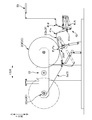
そこで、本実施形態では、このような接合時の張力変動を抑制して資材3をターンバー50へと送出可能なように工夫している。図5は、この工夫を説明するための概略要部拡大側面図である。
すなわち、本実施形態では、蓄積装置40を、資材3の搬送経路におけるターンバー50と資材継ぎ装置20との間の中点位置よりも資材継ぎ装置20寄りに位置させている。より詳しくは、先行の資材3aに後行の資材3fを接合する接合位置Pjから蓄積装置40に到達する到達位置P40aまでの間の資材3(先行の資材3a又は後行の資材3f)の搬送経路の長さを、蓄積装置40からターンバー50へと送出される送出位置P40dからターンバー50に到達する到達位置P50aまでの間の資材3(先行の資材3a又は後行の資材3f)の搬送経路の長さよりも短くしている。
すなわち、本実施形態では、蓄積装置40を、資材3の搬送経路におけるターンバー50と資材継ぎ装置20との間の中点位置よりも資材継ぎ装置20寄りに位置させている。より詳しくは、先行の資材3aに後行の資材3fを接合する接合位置Pjから蓄積装置40に到達する到達位置P40aまでの間の資材3(先行の資材3a又は後行の資材3f)の搬送経路の長さを、蓄積装置40からターンバー50へと送出される送出位置P40dからターンバー50に到達する到達位置P50aまでの間の資材3(先行の資材3a又は後行の資材3f)の搬送経路の長さよりも短くしている。
よって、蓄積装置40が上記中点位置よりもターンバー50寄りに位置している場合と比べて、即時的に張力変動を抑制可能となる。そして、その結果、張力変動を抑制した状態で資材3をターンバー50へと送ることが可能となって、これにより、当該ターンバー50での資材3の蛇行を効果的に防ぐことができる。
ちなみに、上述の「接合位置Pj」のことを、後行の資材コイル3Cfの外周面3Cfsに先行の資材3aを押し付ける押し付け位置Ppと言うこともできる。また、上述の「蓄積装置40に到達する到達位置P40a」とは、一対の定位置ロール41u,41dのうちで上流側に位置する定位置ロール41uに資材3が接触し始める位置のことである。更に、上述の「送出位置P40d」とは、一対の定位置ロール41u,41dのうちで下流側に位置する定位置ロール41dから資材3が離れる位置のことである。また、上述の「ターンバー50に到達する到達位置P50a」とは、資材3がターンバー50に接触し始める位置のことであるが、より詳しくは、図4Bに示すように、資材3の幅方向の中央位置P3Mにおいて同資材3がターンバー50に接触し始める位置のことである。
一方、この例では、繰り出し速度値の指令値(mpm)に対応する指令回転数(rpm)を求めるのに、同指令値(mpm)を資材コイル3Cの外径(m)で除算している。また、このとき用いる外径は、例えばレーザー変位計や超音波変位計等の適宜な不図示のセンサー等により、資材コイル3Cの一回転分の平均径として逐次(例えば1回転毎に)求められる。そして、仮に、資材コイル3Cの外形形状が正円であれば、上記の外径を用いても大きな誤差なく上記の指令値(mpm)に対応する指令回転数(rpm)を求めることができる。しかし、この資材コイル3Cは、不織布やフィルム等の柔軟で可撓性のある連続シート3を巻き取ったコイルであることから、同コイル3Cは変形や偏心等し易く、その結果、資材コイル3Cの周方向の位置に応じて半径の大きさが変動している。そして、この半径の変動は、特に未繰り出し状態等の外径が大きい時に顕著であり、その結果として、後行の資材コイル3Cfの繰り出し開始直後には同コイル3Cfの360°の回転の周期で大きな張力変動が起きる恐れがある。
そこで、この例では、蓄積装置40のループ3Lの全長を、未繰り出し状態の後行の資材コイル3Cfの外周面3Cfsの周長より短くしている。より詳しくは、蓄積装置40の上記到達位置P40aから上記送出位置P40dまでの間の資材3の搬送経路の長さを、未繰り出し状態の後行の資材コイル3Cfの外周面3Cfsの周長より短くしている。
よって、後行の資材コイル3Cfが偏心や半径方向に変形していることに起因して、当該後行の資材コイル3Cfの360°の回転の度に、周期的に生じ得る張力変動にも効果的に対処可能である。すなわち、仮に、このループ3Lの全長が未繰り出し状態の後行の資材コイル3Cfの外周面3Cfsの周長より長い場合、例えば周長の2倍の長さの場合には、当該ループ3Lに、後行の資材コイル3Cfの2周分の張力変動が併存し得るが、そうすると、最初の1周目の張力変動を抑制し難くなってしまう。しかし、この点につき、上記構成によれば、上記のループ3Lの全長を上記外周面3Cfsの周長より短くしているので、2周目の張力変動のループ3Lへの入力前に1周目の張力変動をほぼ抑制することができる。そして、その結果、当該張力変動を確実に抑制可能となる。また、この資材3は伸縮性を有していることから、張力の作用に応じて伸縮し得るが、上記のようにループ3Lの全長を設定していれば、総じてループ3Lの全長を短くできる。よって、資材3の伸び等の影響をより小さくできて、その結果、同資材3の張力変動をより確実に抑えることができる。
ちなみに、図5中にて2点鎖線で示すように、張力変動等に起因して上記のループ3Lの大きさは変化する。そのため、ループ3Lの全長についても変化し得ることから、後行の資材コイル3Cfの外周面3Cfsの周長と比較すべき上述の「ループ3Lの全長(上記搬送経路の長さ)」についても定義する必要があるが、ここでは、当該「ループ3Lの全長(上記搬送経路の長さ)」を、「ループ3Lの大きさが最大の状態での全長(上記搬送経路の長さ)」としている。但し、何等これに限らず、例えば、「ループ3Lの大きさが最小の状態での全長(上記搬送経路の長さ)」と定義しても良いし、「ループ3Lの大きさが最大と最小との間の中間状態での全長(上記搬送経路の長さ)」としても良いし、更に言えば、「ループ3Lの大きさが最大と最小との間の任意の状態での全長(上記搬送経路の長さ)」と定義しても良い。
また、同じく当該周期的な張力変動をより確実に抑制する観点からは、望ましくは、上記接合位置Pjから上記送出位置P40dまでの間の資材3の搬送経路の長さを、未繰り出し状態の後行の資材コイル3Cfの外周面3Cfsの周長より短くすると良い。そして、この例では、そのようにしている。しかし、何等これに限らず、そのようにしなくも良い。
但し、この場合も、上記の搬送経路の長さが、ループの全長の変化に応じて変化し得ることから、この「搬送経路の長さ」についても定義する必要がある。そのため、ここでは、上述と同様に、上記の「搬送経路の長さ」を、「ループ3Lの大きさが最大の状態での搬送経路の長さ」としている。しかし、何等これに限らない。例えば、「ループ3Lの大きさが最小の状態での搬送経路の長さ」と定義しても良いし、「ループ3Lの大きさが最大と最小との間の中間状態での搬送経路の長さ」としても良いし、更に言えば、「ループ3Lの大きさが最大と最小との間の任意の状態での搬送経路の長さ」と定義しても良い。
但し、この場合も、上記の搬送経路の長さが、ループの全長の変化に応じて変化し得ることから、この「搬送経路の長さ」についても定義する必要がある。そのため、ここでは、上述と同様に、上記の「搬送経路の長さ」を、「ループ3Lの大きさが最大の状態での搬送経路の長さ」としている。しかし、何等これに限らない。例えば、「ループ3Lの大きさが最小の状態での搬送経路の長さ」と定義しても良いし、「ループ3Lの大きさが最大と最小との間の中間状態での搬送経路の長さ」としても良いし、更に言えば、「ループ3Lの大きさが最大と最小との間の任意の状態での搬送経路の長さ」と定義しても良い。
更に、図4Aに示すように、この例では、蓄積装置40は、移動ロール41mを1本だけ有している。よって、移動ロール41mが複数本の場合と比べて、移動ロール41mの往復移動の際に同ロール41m自体の慣性起因で資材3の張力が変動してしまうことを抑制することができる。そして、その結果、蓄積装置40は、資材3の張力変動を大きな問題無く抑制可能となる。
また、この慣性起因の張力変動を抑制する観点からは、図5のように、先行の資材3aへの接合後に、後行のコイル3Cfの資材3が搬送ロール29R2との接触を経て蓄積装置40に到達するのは好ましくなく、つまり、望ましくは、図6の概略側面図のように、同後行の資材コイル3Cfから繰り出された資材3が最初に接触する部材が、一対の定位置ロール41u,41dのうちの搬送方向の上流側に位置する定位置ロール41uであると良い。そして、このようになっていれば、上記の搬送ロール29R2の回転動作等の慣性起因で資材3fの張力が変動してしまうような事態を速やかに回避することができて、その結果、蓄積装置40は、資材3の張力変動を大きな問題無く抑制可能となる。
更に、図4Aの例では、前述したように接合時に資材3に大きな張力変動が生じることから、この後行の資材コイル3Cfから資材3fを繰り出す全時間範囲のうちで、蓄積装置40のループ3Lの大きさが最大及び最小となる各時点(同図4A中にて2点鎖線で示すループ3Lの状態を参照)は、後行の資材3fを先行の資材3aに接合する時点を起点として後行の資材コイル3Cfを繰り出す繰り出し用回転軸24が一回転するまでの間に含まれる。よって、作業者は、後行の資材コイル3Cfにおける最初の一巻き分に相当する時間だけ、蓄積装置40のループ3Lを監視していれば、以降、ループの監視をせずに済んで、作業者の監視作業の負荷軽減を図れる。
===その他の実施の形態===
以上、本発明の実施形態について説明したが、上記の実施形態は、本発明の理解を容易にするためのものであり、本発明を限定して解釈するためのものではない。また、本発明は、その趣旨を逸脱することなく、変更や改良され得るとともに、本発明にはその等価物が含まれるのはいうまでもない。例えば、以下に示すような変形が可能である。
以上、本発明の実施形態について説明したが、上記の実施形態は、本発明の理解を容易にするためのものであり、本発明を限定して解釈するためのものではない。また、本発明は、その趣旨を逸脱することなく、変更や改良され得るとともに、本発明にはその等価物が含まれるのはいうまでもない。例えば、以下に示すような変形が可能である。
上述の実施形態では、吸収性物品の一例として所謂展開型の使い捨ておむつ1を例示したが、何等これに限らない。例えば、パンツ型の使い捨ておむつでも良い。更に言えば、吸収性物品は、何等上記の使い捨ておむつ1に限らない。すなわち、着用対象者の排泄液を吸収する物品であれば構わない。例えば吸収性物品が生理用ナプキンや尿取りパッド等であっても良い。
上述の実施形態では、蓄積装置40は、移動ロール41mを1本だけ有していたが、何等これに限らない。すなわち、移動ロール41mを2本又は3本有していても良い。なお、その場合には移動ロール41mが1本増える度に、定位置ロール41u(又は41d)も1本ずつ増設されることになる。
上述の実施形態では、搬送方向変更部材の一例として丸棒のターンバー50を例示したが、何等これに限らない、搬送方向変更部材として例えば帯状の平板部材を用いても良い。
上述の実施形態では、第1方向としてのY方向と第2方向としてのX方向とを交差の一例として平面視で直交させていたが、何等これに限らない。例えば80°という具合に90°以外の角度で両者を交差させても良い。
上述の実施形態では、両面テープ4jで先行の資材3aに後行の資材3fを接合していたが、何等これに限らない。例えば、ヒートシールや超音波シール等の溶着で接合しても良いし、これら以外の接合方法で接合しても良い。
上述の実施形態では、プレス機構26がプレスロール26Rを有していたが、何等これに限らない。例えば、プレスロール26Rに代えて、一対のロールと、当該一対のロールに掛け回された無端ベルトと、を有した構成を用いても良い。そして、この場合には、アクチュエータ26Cの駆動に基づいて、無端ベルトの外周面で、先行の資材3aを後行の資材コイル3Cfの外周面3Cfsの資材3fに押し付けることになる。なお、上記の一対のロールは、両者とも従動ロールであっても良いし、少なくともどちらか一方のロールが駆動ロールでも良い。また、上記の無端ベルトを用いた場合には、先行の資材3aは、同無端ベルトによって後行の資材コイル3Caの周方向の所定範囲に亘って当該後行の資材コイル3Cfの外周面3Cfsに押し付けられることになる場合があるが、その場合の押し付け位置Pp及び接合位置Pjとは、無端ベルトで押し付けられる上記所定範囲における上記周方向の最下流端の位置のことである。
1 使い捨ておむつ(吸収性物品)、2 吸収体、3s 防漏シート、
3 連続シート(資材)、
3C 資材コイル、3Ca 先行の資材コイル、3Cf 後行の資材コイル、
3Cfs 外周面、3Cn 資材コイル、3Cns 外周面、
3L ループ、
3a 先行の資材、3f 後行の資材、3n 資材、
3fe 先端部、3ne 先端部、
3p 紙管、
4j 両面テープ、4k 両面テープ、
10 資材供給装置、20 資材継ぎ装置、21 支持板、22 ターレット、
24’ 回転軸、24a’ 回転軸、24f’ 回転軸、
24 繰り出し用回転軸(回転軸)、
26 プレス機構、26A アーム部材、26C アクチュエータ、
26R プレスロール、
28 カッター機構、28A アーム部材、28B カッター刃、
28C アクチュエータ、
29R1 搬送ロール、29R2 搬送ロール、
40 蓄積装置、41A アーム部材、41C アクチュエータ、
41d 定位置ロール、41m 移動ロール、41u 定位置ロール、
50 ターンバー(搬送方向変更部材)、
110 加工ユニット(加工装置)、110a 積繊機、110b カット装置、
110c プレス装置、110d レッグホールカット装置、
110e エンドカット装置、
LM 製造ライン、LMB 床部、
P3Ca 先行資材コイル位置、P3Cf 後行資材コイル位置、
P3M 中央位置、
Pj 接合位置、Pp 押し付け位置、
C22 旋回軸、C26A 回転軸、C26R 回転軸、
C28A 回転軸、
C41A 回転軸、C41u 回転軸、C41m 回転軸、C41d 回転軸、
P40a 到達位置、P40d 送出位置、P50a 到達位置、
Pw26R 待機位置、Pw28B 待機位置、
Claims (7)
- 資材コイルから連続して繰り出される先行の資材に、別の資材コイルの資材を後行の資材として接合することによって、前記先行の資材に連続させて前記後行の資材を吸収性物品に係る加工装置に供給する資材供給装置であって、
駆動回転する一方の回転軸に支持された前記先行の資材コイルから繰り出される前記先行の資材を、前記後行の資材コイルを支持する他方の回転軸の駆動回転動作によって回転する前記後行の資材コイルの外周面に向けて押し付けることにより、前記先行の資材に前記後行の資材を接合する資材継ぎ装置と、
前記資材継ぎ装置から連続して送られる前記先行の資材又は前記後行の資材をループの形態で蓄積可能な蓄積装置と、
前記蓄積装置から第1方向を搬送方向として送られる前記先行の資材又は前記後行の資材を、平面視で前記第1方向と交差する第2方向に搬送方向を変更して前記加工装置へ送る搬送方向変更部材と、を有し、
少なくとも前記後行の資材の前記先行の資材への接合後には、前記ループの大きさが一定となるように前記他方の回転軸の駆動回転動作が制御され、
前記先行の資材に前記後行の資材を接合する接合位置から、前記蓄積装置に到達する到達位置までの間の前記先行の資材又は前記後行の資材の搬送経路の長さは、前記蓄積装置から前記搬送方向変更部材へと送出される送出位置から前記搬送方向変更部材に到達する到達位置までの間の前記先行の資材又は前記後行の資材の搬送経路の長さよりも短いことを特徴とする吸収性物品に係る資材供給装置。 - 請求項1に記載の吸収性物品に係る資材供給装置であって、
前記蓄積装置の前記到達位置から前記送出位置までの間の前記先行の資材又は前記後行の資材の搬送経路の長さは、未繰り出し状態の前記後行の資材コイルの外周面の周長より短いことを特徴とする吸収性物品に係る資材供給装置。 - 請求項2に記載の吸収性物品に係る資材供給装置であって、
前記接合位置から前記送出位置までの間の前記先行の資材又は前記後行の資材の搬送経路の長さは、未繰り出し状態の前記後行の資材コイルの外周面の周長より短いことを特徴とする吸収性物品に係る資材供給装置。 - 請求項1乃至3の何れかに記載の吸収性物品に係る資材供給装置であって、
前記蓄積装置は、定位置で回転可能に支持された一対の定位置ロールと、前記ループの大きさを変更可能な方向に往復移動可能に案内された移動ロールと、を有し、
前記一対の定位置ロール同士の間で前記移動ロールに前記先行の資材又は前記後行の資材が掛け回されることにより前記ループが形成され、
前記蓄積装置は、前記移動ロールを1本だけ有していることを特徴とする吸収性物品に係る資材供給装置。 - 請求項4に記載の吸収性物品に係る資材供給装置であって、
前記先行の資材への接合後に、前記後行の資材コイルから繰り出された前記後行の資材が最初に接触する部材は、前記一対の定位置ロールのうちの前記搬送方向の上流側に位置する定位置ロールであることを特徴とする吸収性物品に係る資材供給装置。 - 請求項1乃至5の何れかに記載の吸収性物品に係る資材供給装置であって、
前記後行の資材コイルからの前記後行の資材の繰り出し動作において前記ループの大きさが最大及び最小となる各時点は、前記後行の資材を前記先行の資材に接合する時点を起点として前記他方の回転軸が一回転するまでの間に含まれていることを特徴とする吸収性物品に係る資材供給装置。 - 資材コイルから連続して繰り出される先行の資材に、別の資材コイルの資材を後行の資材として接合することによって、前記先行の資材に連続させて前記後行の資材を吸収性物品に係る加工装置に供給する資材供給方法であって、
駆動回転する一方の回転軸に支持された前記先行の資材コイルから繰り出される前記先行の資材を、前記後行の資材コイルを支持する他方の回転軸の駆動回転動作によって回転する前記後行の資材コイルの外周面に向けて押し付けることにより、資材継ぎ装置が前記先行の資材に前記後行の資材を接合することと、
前記資材継ぎ装置から連続して送られる前記先行の資材又は前記後行の資材をループの形態で蓄積装置が蓄積することと、
前記蓄積装置から第1方向を搬送方向として送られる前記先行の資材又は前記後行の資材を、搬送方向変更部材が、平面視で前記第1方向と交差する第2方向に搬送方向を変更して前記加工装置へ送ることと、を有し、
少なくとも前記後行の資材の前記先行の資材への接合後には、前記ループの大きさが一定となるように前記他方の回転軸の駆動回転動作が制御され、
前記先行の資材に前記後行の資材を接合する接合位置から、前記蓄積装置に到達する到達位置までの間の前記先行の資材又は前記後行の資材の搬送経路の長さは、前記蓄積装置から前記搬送方向変更部材へと送出される送出位置から前記搬送方向変更部材に到達する到達位置までの間の前記先行の資材又は前記後行の資材の搬送経路の長さよりも短いことを特徴とする吸収性物品に係る資材供給方法。
Priority Applications (3)
| Application Number | Priority Date | Filing Date | Title |
|---|---|---|---|
| JP2016544879A JP6043896B1 (ja) | 2016-02-29 | 2016-02-29 | 吸収性物品に係る資材供給装置、及び資材供給方法 |
| PCT/JP2016/056098 WO2017149610A1 (ja) | 2016-02-29 | 2016-02-29 | 吸収性物品に係る資材供給装置、及び資材供給方法 |
| CN201680082805.2A CN108698777B (zh) | 2016-02-29 | 2016-02-29 | 与吸收性物品相关联的用于供给材料的设备及方法 |
Applications Claiming Priority (1)
| Application Number | Priority Date | Filing Date | Title |
|---|---|---|---|
| PCT/JP2016/056098 WO2017149610A1 (ja) | 2016-02-29 | 2016-02-29 | 吸収性物品に係る資材供給装置、及び資材供給方法 |
Publications (1)
| Publication Number | Publication Date |
|---|---|
| WO2017149610A1 true WO2017149610A1 (ja) | 2017-09-08 |
Family
ID=57543896
Family Applications (1)
| Application Number | Title | Priority Date | Filing Date |
|---|---|---|---|
| PCT/JP2016/056098 WO2017149610A1 (ja) | 2016-02-29 | 2016-02-29 | 吸収性物品に係る資材供給装置、及び資材供給方法 |
Country Status (3)
| Country | Link |
|---|---|
| JP (1) | JP6043896B1 (ja) |
| CN (1) | CN108698777B (ja) |
| WO (1) | WO2017149610A1 (ja) |
Cited By (3)
| Publication number | Priority date | Publication date | Assignee | Title |
|---|---|---|---|---|
| WO2019151052A1 (ja) | 2018-01-31 | 2019-08-08 | 株式会社瑞光 | シート供給方法及びシート供給装置 |
| WO2019181648A1 (ja) * | 2018-03-20 | 2019-09-26 | ユニ・チャーム株式会社 | 吸収性物品製造方法及び吸収性物品製造装置 |
| CN114803630A (zh) * | 2022-04-27 | 2022-07-29 | 佛山科学技术学院 | 非晶带材双侧卷绕装置及方法 |
Families Citing this family (1)
| Publication number | Priority date | Publication date | Assignee | Title |
|---|---|---|---|---|
| CN109573696B (zh) * | 2019-01-29 | 2020-02-07 | 黄仕 | 双放料自动连接架 |
Citations (6)
| Publication number | Priority date | Publication date | Assignee | Title |
|---|---|---|---|---|
| JPS62201762A (ja) * | 1986-02-28 | 1987-09-05 | Tokiwa Kogyo Kk | 包装機等に於けるフイルム接合方法 |
| US5643395A (en) * | 1992-09-01 | 1997-07-01 | Cms Gilbreth Packaging Systems, Inc. | Automatic splicing apparatus |
| JP2003327354A (ja) * | 2002-05-10 | 2003-11-19 | Zuiko Corp | ウエブの継ぎ方法および継ぎ装置 |
| JP2005298162A (ja) * | 2004-04-13 | 2005-10-27 | Daio Paper Corp | スプライス装置及びスプライス方法 |
| JP2008105808A (ja) * | 2006-10-25 | 2008-05-08 | Mitsubishi Heavy Ind Ltd | 印刷機および給紙装置による紙継ぎ方法 |
| JP2014012599A (ja) * | 2012-07-05 | 2014-01-23 | Uni Charm Corp | 資材継ぎ装置 |
Family Cites Families (2)
| Publication number | Priority date | Publication date | Assignee | Title |
|---|---|---|---|---|
| US6540170B2 (en) * | 2001-07-23 | 2003-04-01 | Illinois Tool Works Inc. | Multiple coil dispenser |
| JP2011116513A (ja) * | 2009-12-04 | 2011-06-16 | Unicharm Corp | 帯状物供給装置及びその作動方法 |
-
2016
- 2016-02-29 WO PCT/JP2016/056098 patent/WO2017149610A1/ja active Application Filing
- 2016-02-29 CN CN201680082805.2A patent/CN108698777B/zh active Active
- 2016-02-29 JP JP2016544879A patent/JP6043896B1/ja active Active
Patent Citations (6)
| Publication number | Priority date | Publication date | Assignee | Title |
|---|---|---|---|---|
| JPS62201762A (ja) * | 1986-02-28 | 1987-09-05 | Tokiwa Kogyo Kk | 包装機等に於けるフイルム接合方法 |
| US5643395A (en) * | 1992-09-01 | 1997-07-01 | Cms Gilbreth Packaging Systems, Inc. | Automatic splicing apparatus |
| JP2003327354A (ja) * | 2002-05-10 | 2003-11-19 | Zuiko Corp | ウエブの継ぎ方法および継ぎ装置 |
| JP2005298162A (ja) * | 2004-04-13 | 2005-10-27 | Daio Paper Corp | スプライス装置及びスプライス方法 |
| JP2008105808A (ja) * | 2006-10-25 | 2008-05-08 | Mitsubishi Heavy Ind Ltd | 印刷機および給紙装置による紙継ぎ方法 |
| JP2014012599A (ja) * | 2012-07-05 | 2014-01-23 | Uni Charm Corp | 資材継ぎ装置 |
Cited By (6)
| Publication number | Priority date | Publication date | Assignee | Title |
|---|---|---|---|---|
| WO2019151052A1 (ja) | 2018-01-31 | 2019-08-08 | 株式会社瑞光 | シート供給方法及びシート供給装置 |
| WO2019181648A1 (ja) * | 2018-03-20 | 2019-09-26 | ユニ・チャーム株式会社 | 吸収性物品製造方法及び吸収性物品製造装置 |
| JP2019163132A (ja) * | 2018-03-20 | 2019-09-26 | ユニ・チャーム株式会社 | 吸収性物品製造方法及び吸収性物品製造装置 |
| JP7085376B2 (ja) | 2018-03-20 | 2022-06-16 | ユニ・チャーム株式会社 | 吸収性物品製造方法及び吸収性物品製造装置 |
| CN114803630A (zh) * | 2022-04-27 | 2022-07-29 | 佛山科学技术学院 | 非晶带材双侧卷绕装置及方法 |
| CN114803630B (zh) * | 2022-04-27 | 2024-01-12 | 佛山科学技术学院 | 非晶带材双侧卷绕装置及方法 |
Also Published As
| Publication number | Publication date |
|---|---|
| JP6043896B1 (ja) | 2016-12-14 |
| CN108698777B (zh) | 2019-09-24 |
| JPWO2017149610A1 (ja) | 2018-03-08 |
| CN108698777A (zh) | 2018-10-23 |
Similar Documents
| Publication | Publication Date | Title |
|---|---|---|
| JP6043896B1 (ja) | 吸収性物品に係る資材供給装置、及び資材供給方法 | |
| US8062459B2 (en) | Velocity-changing apparatus for web | |
| US9016176B2 (en) | Web member cutting apparatus for cutting web member that has a plurality of fibers including tows and web member cutting method | |
| KR101204119B1 (ko) | 다기능 풀기 디바이스 | |
| JP4573748B2 (ja) | 帯状シートの製造方法 | |
| JP2015506320A (ja) | リール巻出し機及び巻出し方法 | |
| JP2019034852A (ja) | 巻き出しアセンブリ、および巻き出しアセンブリにリールを自動的に装填するための方法 | |
| JP2005089177A (ja) | ウェブ巻替え装置及び方法 | |
| JP6051351B1 (ja) | 資材継ぎ方法、及び、資材供給装置 | |
| JP2010036990A (ja) | ウェブ巻取り装置及び方法 | |
| CN111107815A (zh) | 用于施加吸收性物品的部段的设备 | |
| JP6051349B1 (ja) | 吸収性物品の製造方法、及び製造装置 | |
| EP2508455A1 (en) | Belt-form body supply device and method of operation thereof | |
| JP6051350B1 (ja) | 資材供給装置、及び、吸収性物品の製造装置 | |
| CN111867950B (zh) | 吸收性物品制造方法以及吸收性物品制造装置 | |
| WO2020138200A1 (ja) | 吸収性物品に係る連続シートの複合体を製造する方法、及び、製造装置 | |
| JP6134512B2 (ja) | 伸縮性シートの製造装置、及び製造方法 |
Legal Events
| Date | Code | Title | Description |
|---|---|---|---|
| ENP | Entry into the national phase |
Ref document number: 2016544879 Country of ref document: JP Kind code of ref document: A |
|
| NENP | Non-entry into the national phase |
Ref country code: DE |
|
| 121 | Ep: the epo has been informed by wipo that ep was designated in this application |
Ref document number: 16892455 Country of ref document: EP Kind code of ref document: A1 |
|
| 122 | Ep: pct application non-entry in european phase |
Ref document number: 16892455 Country of ref document: EP Kind code of ref document: A1 |