WO2017148409A1 - Machine à café et procédé de commande de celle-ci - Google Patents
Machine à café et procédé de commande de celle-ci Download PDFInfo
- Publication number
- WO2017148409A1 WO2017148409A1 PCT/CN2017/075428 CN2017075428W WO2017148409A1 WO 2017148409 A1 WO2017148409 A1 WO 2017148409A1 CN 2017075428 W CN2017075428 W CN 2017075428W WO 2017148409 A1 WO2017148409 A1 WO 2017148409A1
- Authority
- WO
- WIPO (PCT)
- Prior art keywords
- pressure
- assembly
- component
- brewing
- coffee
- Prior art date
Links
Images


Classifications
-
- A—HUMAN NECESSITIES
- A47—FURNITURE; DOMESTIC ARTICLES OR APPLIANCES; COFFEE MILLS; SPICE MILLS; SUCTION CLEANERS IN GENERAL
- A47J—KITCHEN EQUIPMENT; COFFEE MILLS; SPICE MILLS; APPARATUS FOR MAKING BEVERAGES
- A47J31/00—Apparatus for making beverages
- A47J31/24—Coffee-making apparatus in which hot water is passed through the filter under pressure, i.e. in which the coffee grounds are extracted under pressure
-
- A—HUMAN NECESSITIES
- A47—FURNITURE; DOMESTIC ARTICLES OR APPLIANCES; COFFEE MILLS; SPICE MILLS; SUCTION CLEANERS IN GENERAL
- A47J—KITCHEN EQUIPMENT; COFFEE MILLS; SPICE MILLS; APPARATUS FOR MAKING BEVERAGES
- A47J31/00—Apparatus for making beverages
- A47J31/42—Beverage-making apparatus with incorporated grinding or roasting means for coffee
-
- A—HUMAN NECESSITIES
- A23—FOODS OR FOODSTUFFS; TREATMENT THEREOF, NOT COVERED BY OTHER CLASSES
- A23F—COFFEE; TEA; THEIR SUBSTITUTES; MANUFACTURE, PREPARATION, OR INFUSION THEREOF
- A23F5/00—Coffee; Coffee substitutes; Preparations thereof
- A23F5/24—Extraction of coffee; Coffee extracts; Making instant coffee
- A23F5/26—Extraction of water-soluble constituents
-
- A—HUMAN NECESSITIES
- A47—FURNITURE; DOMESTIC ARTICLES OR APPLIANCES; COFFEE MILLS; SPICE MILLS; SUCTION CLEANERS IN GENERAL
- A47J—KITCHEN EQUIPMENT; COFFEE MILLS; SPICE MILLS; APPARATUS FOR MAKING BEVERAGES
- A47J31/00—Apparatus for making beverages
- A47J31/06—Filters or strainers for coffee or tea makers ; Holders therefor
- A47J31/0626—Filters or strainers for coffee or tea makers ; Holders therefor with means for securing the filter holder to the beverage container
-
- A—HUMAN NECESSITIES
- A47—FURNITURE; DOMESTIC ARTICLES OR APPLIANCES; COFFEE MILLS; SPICE MILLS; SUCTION CLEANERS IN GENERAL
- A47J—KITCHEN EQUIPMENT; COFFEE MILLS; SPICE MILLS; APPARATUS FOR MAKING BEVERAGES
- A47J31/00—Apparatus for making beverages
- A47J31/18—Apparatus in which ground coffee or tea-leaves are immersed in the hot liquid in the beverage container
-
- A—HUMAN NECESSITIES
- A47—FURNITURE; DOMESTIC ARTICLES OR APPLIANCES; COFFEE MILLS; SPICE MILLS; SUCTION CLEANERS IN GENERAL
- A47J—KITCHEN EQUIPMENT; COFFEE MILLS; SPICE MILLS; APPARATUS FOR MAKING BEVERAGES
- A47J31/00—Apparatus for making beverages
- A47J31/44—Parts or details or accessories of beverage-making apparatus
- A47J31/4403—Constructional details
-
- A—HUMAN NECESSITIES
- A47—FURNITURE; DOMESTIC ARTICLES OR APPLIANCES; COFFEE MILLS; SPICE MILLS; SUCTION CLEANERS IN GENERAL
- A47J—KITCHEN EQUIPMENT; COFFEE MILLS; SPICE MILLS; APPARATUS FOR MAKING BEVERAGES
- A47J31/00—Apparatus for making beverages
- A47J31/44—Parts or details or accessories of beverage-making apparatus
- A47J31/46—Dispensing spouts, pumps, drain valves or like liquid transporting devices
- A47J31/462—Dispensing spouts, pumps, drain valves or like liquid transporting devices with an intermediate liquid storage tank
- A47J31/465—Dispensing spouts, pumps, drain valves or like liquid transporting devices with an intermediate liquid storage tank for the heated water
-
- A—HUMAN NECESSITIES
- A47—FURNITURE; DOMESTIC ARTICLES OR APPLIANCES; COFFEE MILLS; SPICE MILLS; SUCTION CLEANERS IN GENERAL
- A47J—KITCHEN EQUIPMENT; COFFEE MILLS; SPICE MILLS; APPARATUS FOR MAKING BEVERAGES
- A47J31/00—Apparatus for making beverages
- A47J31/44—Parts or details or accessories of beverage-making apparatus
- A47J31/46—Dispensing spouts, pumps, drain valves or like liquid transporting devices
- A47J31/462—Dispensing spouts, pumps, drain valves or like liquid transporting devices with an intermediate liquid storage tank
- A47J31/467—Dispensing spouts, pumps, drain valves or like liquid transporting devices with an intermediate liquid storage tank for the infusion
Definitions
- the invention relates to the technical field of coffee brewing, in particular to a coffee machine and a control method thereof.
- the coffee liquid is usually prepared by soaking the hot water in the hot water and passing through the natural drip, which may cause the problem that the coffee powder is insufficiently dissolved and the brewing speed is slow, which affects the user's use. .
- a coffee machine comprising:
- a brewing assembly comprising a brewing container, the brewing container being mounted on the casing body, the brewing container having a hollow receiving cavity, the receiving cavity being capable of accommodating the brewed product;
- the light pressure component comprises a pressure pump and a pressure pipe, the pressure pump is connected to the pressure pipe, and the pressure pipe is connected to the receiving cavity
- the pressure pump is capable of providing pressure to the brewing container
- a heating assembly mounted in the housing body, and wherein the heating assembly is in communication with the receiving chamber, the heating assembly providing hot water to the brewing container;
- a filter assembly is mounted below the brewing vessel, the filter assembly being in communication with the containment chamber.
- the coffee machine further includes a control component, the control component including a control panel and a control board;
- the control panel is disposed on the casing body, the control board is disposed in the casing body, and the control board is electrically connected to the control panel;
- the control board is electrically connected to the brewing component, the control board is electrically connected to the heating component, and the control board is electrically connected to the light press component.
- the pressure supplied by the pressurizing pump to the receiving chamber is less than 0.4 MPa.
- the brewing container is further provided with a powder inlet hole, a water inlet hole and a vent hole;
- the water inlet hole is in communication with the heating assembly
- the powder inlet hole, the water inlet hole and the exhaust hole communicate with the receiving chamber.
- the brewing assembly further includes a transmission mechanism and a cavity top seal
- the transmission mechanism is mounted on the cavity top seal, and the transmission mechanism is configured to drive the cavity top seal to seal the powder inlet hole, the water inlet hole and the vent hole.
- the brewing assembly further includes a quick clip, the quick clip mounting the filter assembly on the brewing container;
- the quick clip has a handle and a clamping portion, the handle is mounted on the clamping portion, the clamping portion connects the filter assembly and the brewing container, and the handle is rotated to a preset position
- the clamping portion can be clamped to the filter assembly and the brewing container to secure and seal the filter assembly.
- the filter assembly includes a filter and a filter cup, the filter cup having a liquid outlet end;
- the filter is mounted in the filter cup, the filter cup being mounted on the brewing container, the filter cup being in communication with the receiving chamber.
- the coffee machine further includes a pressure relief assembly, the pressure relief assembly being mounted in the liquid outlet end of the filter cup;
- the pressure relief assembly includes a pressure relief valve and a pressure relief spring, the pressure relief valve is coupled to the pressure relief spring and mounted in the liquid discharge end, the pressure relief valve capable of sealing the liquid outlet end;
- the pressure relief valve compresses the pressure relief spring to open the liquid discharge end.
- the coffee machine further comprises an automatic powder separation component or a grinder component
- the automatic powder dividing component or the grinding bean component is installed in the casing body;
- the heating assembly is a water storage type boiler or a thermal heating element.
- Step S100 adding coffee powder to the brewing container of the brewing component
- Step S200 The control component controls the heating component to add hot water to the accommodating cavity of the brewing container, and after adding a preset amount of water, the heating component stops heating the water to the accommodating cavity;
- Step S300 the control component controls the adding light pressure component to discharge the gas into the hot water of the brewing container, and forms a bubble, the air bubble floating upward and rupturing, so that the hot water and the hot water in the brewing container The brew is thoroughly mixed;
- Step S400 the control component controls the cavity top seal to seal the vent hole, and controls the adding light pressure component to continuously discharge a gas into the accommodating cavity to form a pressure to extract the brewed object a substance that thoroughly mixes the hot water with the brewed material to form a mixed solution;
- Step S500 the control component controls the adding light pressure component to continuously apply pressure to the accommodating cavity, pressing the mixed solution in the brewing container to the filter component, and passing the mixed solution
- the filter component is filtered and output.
- the coffee machine and the control method thereof of the invention have simple and reasonable structural design.
- the heating component heats the water into the accommodating cavity, so that the coffee powder is fully mixed with the hot water, and then passed.
- the light pressure component is applied to the accommodating chamber to extract the substance in the coffee powder by a slight pressure, so that the coffee powder can be fully dissolved in the hot water to obtain a high-quality brewed coffee liquid, so that the coffee liquid is concentrated and fine.
- the slippery, mouthfeel and the like have been improved, and the brewing efficiency of the coffee liquid is improved, which is convenient for the user to use.
- Figure 1 is a perspective view of a coffee machine in accordance with an embodiment of the present invention
- Figure 2 is a perspective view of the coffee machine of Figure 1 with the body removed;
- FIG. 3 is a schematic structural view of a brewing component, a filter assembly, and a light pressure component in the coffee machine shown in FIG. 2;
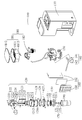
- Figure 4 is an exploded view of the coffee machine shown in Figure 1;
- 5A, 5B, 5C, and 5D are schematic views of the coffee machine shown in Fig. 1 during brewing;
- Fig. 6 is a schematic view showing the operation of the coffee machine shown in Fig. 1.
- 100-coffee machine 110-case body; 120- brewing component; 121- brewing container; 1211-inlet hole; 1212-inlet hole; 1213-venting hole; 122-drive mechanism; -motor;1222-motor support;123-transmission mechanism;1231-gear;1232-rack;1233-transmission rod;1214-card position;124-limit mechanism;1241-stroke switch;1242-stop ejector 125-cavity top seal; 126-cavity bottom seal; 127-fast clamp; 130-heating assembly; 140-plus light pressure assembly; 141-pressure pump; 142-pressure pipe; 150-filter assembly; Filter cup; 1511-outlet end; 152-filter; 153-fixing ring; 160-control assembly; 161-control panel; 162-control board; 170-pressure relief assembly; 171-pressure relief valve; Spring; 173 - pressure relief seal; 180 - grinder component; 181 - bean storage mechanism; 1811 - bean box; 1821 bean cover;
- the present invention provides a coffee maker 100, and more particularly a brewing apparatus, the coffee maker 100 being primarily used for brewing coffee liquor.
- the coffee machine 100 of the present invention can also be used for the brewing of mixed drinks, as well as the soaking of teas.
- the coffee maker 100 includes a cabinet body 110, a brewing assembly 120, a light press assembly 140, a heating assembly 130, and a filter assembly 150.
- the brewing component 120, the light-pressing component 140 and the heating component 130 are both mounted in the casing body 110, and the filter component 150 is mounted on the brewing component 120, and the casing body 110 serves as a supporting body to support the brewing component 120 and The assembly 140 and the heating assembly 130 are lightly pressed.
- the brewing component 120 is the primary component used to brew the brewed material.
- the brewed material is coffee powder, tea, mixed drinks, etc., and after the brewed product is added to the brewing unit 120, the hot water supplied from the heating unit 130 can be mixed with the brewed product to form a mixed solution.
- the brewed material is exemplified as coffee powder, and the coffee powder is mixed with hot water to form a coffee liquid.
- the heating assembly 130 is capable of providing hot water to the brewing assembly 120 such that the ground coffee in the brewing assembly 120 is soaked in hot water.
- the light press assembly 140 is capable of providing a slight pressure into the brewing assembly to ensure that the coffee powder in the brewing assembly 120 is sufficiently extracted so that the coffee powder and hot water can be thoroughly mixed to obtain a high quality coffee liquid.
- the filter assembly 150 can filter the coffee liquid, filter particles such as impurities existing in the coffee liquid, and further ensure the fineness and texture of the coffee liquid to meet the user's demand for high quality life.
- the brewing unit 120 includes a brewing container 121, and the brewing container 121 is mounted on the casing body 110.
- the brewing container 121 has a hollow receiving chamber capable of accommodating the brewed material, that is, coffee powder.
- the receiving chamber of the brewing container 121 is a through hole, one end of which is sealed by the cavity top seal 125 of the brewing container 121, and the other end of the through hole is sealed by the filter assembly 150. That is to say, the tightness of the accommodating chamber is ensured by the cavity top seal 125, the brewing container 121 and the filter assembly 150, so as to add a light pressure to the accommodating chamber.
- One end of the through hole connected to the filter assembly 150 is a liquid outlet, and the coffee liquid in the brewing container 121 flows into the filter assembly 150 through the liquid outlet.
- the heating assembly 130 is in communication with the accommodating chamber, and the heating assembly 130 supplies hot water to the brewing container 121 so that the coffee powder in the accommodating chamber can be immersed in the hot water. Moreover, the user can select different hot water temperatures and soaking time of the coffee powder according to different taste requirements, which is convenient for the user to use.
- the light pressure assembly 140 is in communication with the accommodating chamber, and the light pressure assembly 140 is applied to supply pressure to the brewing container 121 to extract the substance in the coffee powder in a slight air pressure manner.
- the heating assembly 130 and the light-pressing assembly 140 are operated in the order of first heating the water into the brewing container 121 through the heating assembly 130, soaking the coffee powder; and adding a slight air to the brewing container 121 by adding the light-pressing assembly 140.
- the pressure allows the soaked coffee powder to be sufficiently extracted so that the coffee powder can be sufficiently dissolved in the hot water to obtain a high quality brewed coffee liquid.
- the filter assembly 150 is capable of functioning as a protection and discharge.
- the filter assembly 150 is installed under the brewing container 121, and the filter assembly 150 communicates with the accommodating chamber, so that the coffee liquid in the brewing container 121 is filtered through the filter assembly 150 to remove particles such as impurities in the coffee liquid to ensure the mouthfeel of the coffee liquid.
- the coffee liquid in the brewing container 121 is pressed out by adding the light pressure unit 140, or is pumped out.
- the coffee liquid in the brewing container 121 is passed through the light pressure component 140. Press out.
- the filter assembly 150 has a liquid outlet end 1511. The coffee liquid is sealed during the brewing process.
- the light pressure component 140 adds a slight pressure to the brewing container 121 to extract the substance in the coffee powder. After the brewing of the coffee liquid is completed, the liquid outlet end 1511 is opened, and the light pressure component 140 is continuously added to the brewing container 121 to lightly press, and the coffee liquid in the brewing container 121 is filtered by the filter assembly 150 under the action of slight pressure. It is output from the liquid discharge end 1511. It is convenient and quick to increase the brewing speed of coffee liquid and is convenient for users.
- the shape of the receiving chamber is not limited as long as the hot water can be soaked in the coffee powder. And the user can choose different soaking time according to the use requirements to ensure the proper dissolution of the coffee powder and increase the extraction effect.
- the coffee machine 100 of the invention adopts the method of air pressure to realize intelligent automatic brewing, and the material in the coffee powder is extracted by a unique slight pressure method to obtain high quality brewed coffee liquid, in concentration, temperature and smoothness. The taste and taste are improved to the traditional classic coffee machine and the traditional pressure coffee machine can not obtain the quenching effect.
- the coffee machine usually adopts a method of soaking hot water to the coffee powder and preparing the coffee liquid by natural dripping, so that there is a problem that the coffee powder is insufficiently dissolved and the brewing speed is slow, and at the same time, the pressure coffee machine has a manufacturing cost. High, use of shortcomings and other shortcomings, affecting the user's use.
- the coffee machine 100 of the present invention adds the coffee powder into the accommodating cavity of the brewing container 121, the water is heated in the accommodating chamber through the heating assembly 130, so that the coffee powder is sufficiently mixed with the hot water, and then accommodated by adding the light pressure component 140.
- the coffee machine 100 of the present invention has a simple structure, a low manufacturing cost, and reduces the burden on the user. Moreover, the coffee machine 100 of the present invention has a simple structure, is convenient for the user to operate, and saves time.
- the coffee machine 100 further includes a control component 160.
- the control component 160 includes a control panel 161 and a control main board 162.
- the control panel 161 is disposed on the casing body 110.
- the control mainboard 162 is disposed in the casing body 110, and the control mainboard 162 and the control The panel 161 is electrically connected; the control board 162 is electrically connected to the brewing component 120, the control board 162 is electrically connected to the heating component 130, and the control board 162 is electrically connected to the light-pressing component 140.
- the coffee machine 100 realizes an intelligent operation through the control component 160, speeds up the intelligent process of the coffee machine 100, and is convenient for the user to use.
- the control panel 161 is provided with various touch buttons, such as the heating temperature of the heating assembly 130, the soaking time of the coffee powder, the pressure applied by the pressure pump 141, etc., and the user can select according to his own needs, which can satisfy different users' use. Demand, easy to use.
- the control main board 162 stores the control program, and can control the heating unit 130, the brewing unit 120, and the light pressure unit 140 to operate.
- the light-pressing assembly 140 includes a pressurizing pump 141 and a pressure conduit 142; the pressurizing pump 141 is coupled to the pressure conduit 142, and the pressure conduit 142 is in communication with the receiving chamber.
- the pressure pump 141 delivers a slight pressure through the pressure line 142 into the receiving chamber of the brewing container 121 to effect the lightly brewing coffee liquid of the coffee machine 100.
- the pressurizing pump 141 is mounted in the casing body 110, and the pressure pipe 142 is connected to the brewing vessel 121 through the casing body 110, and the pressure pipe 142 communicates with the accommodating cavity through the top or side wall of the brewing vessel 121. It should be noted that the pressure pipe 142 passes through the brewing container.
- the nozzle of the pressure tube 142 in the accommodating chamber is preferably lower than the liquid level of the coffee liquid in the accommodating chamber, so that the pressure pump 141 can add a slight pressure to the accommodating chamber to make the coffee Air bubbles are generated inside the liquid, and the bubbles rise and break, which can be stirred and mixed, so that the coffee powder can be thoroughly mixed with hot water to increase the coffee concentration in the coffee liquid and the quenching rate of the coffee powder, and improve the coffee liquid. The taste and so on.
- the pressure supplied by the pressurizing pump 141 to the accommodating chamber is less than 0.4 MPa. That is to say, the pressure pump 141 applies a slight pressure to the accommodating chamber of the brewing container 121, and the pressure provided by the pressurizing pump 141 is less than 0.4 MPa, which can meet the requirements of the extraction of the substance in the coffee powder, and ensure that the coffee powder can be sufficiently Dissolved in hot water and filtered from filter assembly 150. Further, when the pressure applied by the pressurizing pump 141 is large, the sealing requirements for the brewing container 121 and the quality of the pressurizing pump 141 are high, which increases the manufacturing cost of the coffee maker 100 and is inconvenient for the user to use.
- the pressure of the pressure pump 141 of the present invention of less than 0.4 MPa can satisfy the extraction requirements of the coffee powder, while ensuring the safety of the operation of the coffee machine 100 and avoiding the occurrence of a safety accident.
- the pressure supplied by the pressurizing pump 141 to the accommodating chamber ranges from 0.15 MPa to 0.25 MPa.
- the coffee machine 100 of the present invention enables coffee brewing in a lightly compressed brewing manner.
- the brewed hot water and coffee powder are soaked in the accommodating chamber of the brewing container 121 and mixed into coffee liquid, and the light pressure component 140 is applied to the coffee powder in the accommodating chamber by a slight pressure on the air pressure to lightly pressurize the pressure.
- the material in the coffee powder is extracted, so that the coffee powder can be sufficiently dissolved in the hot water to effectively improve the quality of the brewed coffee liquid, and then the coffee is hydraulically discharged out of the filter assembly 150 by a slight air pressure.
- the brewing container 121 is further provided with a powder inlet hole 1211, a water inlet hole 1212 and a vent hole 1213; the powder inlet hole 1211, the water inlet hole 1212 and the vent hole 1213 communicate with the accommodating cavity.
- the ground coffee enters the accommodating chamber of the brewing container 121 through the powder feeding hole 1211.
- the water inlet hole 1212 is in communication with the heating assembly 130, and the heating assembly 130 conveys hot water through the water inlet hole 1212 into the accommodating chamber to soak the coffee powder in the brewing container 121.
- a venting opening 1213 is added to the brewing container 121, and the venting opening 1213 communicates with the accommodating chamber when the heating assembly 130 is in the accommodating chamber.
- the hot water enters the accommodating chamber from the water inlet hole 1212, and the air in the accommodating chamber is discharged to the accommodating chamber through the vent hole 1213 to ensure the pressure balance in the accommodating chamber.
- the brewing assembly 120 further includes a driving mechanism 122, a transmission mechanism 123 and a cavity top seal 125; the driving mechanism 122 is coupled to the transmission mechanism 123, and the transmission mechanism 123 is mounted on the cavity top sealing member 125, and the driving mechanism The drive mechanism 123 is moved, and the transmission mechanism 123 can drive the cavity top seal 125 to seal into the powder hole 1211, the water inlet hole 1212 and the vent hole 1213.
- the driving component includes a motor 1221 and a motor supporting base 1222.
- the motor supporting base 1222 is mounted on the casing body 110, and the motor 1221 is mounted on the motor supporting base 1222.
- the transmission mechanism 123 includes a gear 1231, a rack 1232 and a transmission rod 1233.
- the gear 1231 is mounted on the output shaft of the motor 1221, the rack 1232 is mounted to the transmission rod 1233, and the transmission rod 1233 is mounted to the ceiling seal 125.
- the motor 1221 rotates and drives the gear 1231 to rotate, the gear 1231 meshes with the rack 1232, and the cooperation of the gear 1231 and the rack 1232 can convert the rotational motion into a linear motion, and the gear 1231 drives the rack 1232 to perform a linear motion, thereby driving the transmission rod 1233.
- the top seal 125 is sealed thereon
- the powder inlet hole 1211, the water inlet hole 1212 and the vent hole 1213 ensure the sealing property of the accommodating chamber, so that the light pressure component 140 does not leak when the light pressure is applied to the accommodating chamber.
- the brewing assembly 120 further includes a limiting mechanism 124 mounted on the motor support 1222.
- the limit mechanism 124 includes a travel switch 1241 and a stop ejector 1242.
- the travel switch 1241 and the stop ejector 1242 are both mounted on the motor support 1222.
- the travel switch 1241 can limit the linear motion of the rack 1232 to prevent the teeth.
- the strip 1232 is overstroke; the stop ejector 1242 ensures the reliability of the seal of the top seal 125, preventing the position of the top seal 125 from being misaligned, so as not to affect the sealing effect.
- the driving mechanism 122 controls the transmission mechanism 123 to drive the cavity top sealing member 125 to first seal into the powder hole 1211, and then the heating assembly 130 transfers the hot water to the brewing container 121. Moreover, when the amount of hot water in the brewing container 121 reaches the demand, the heating assembly 130 stops adding hot water, and at the same time, the light pressing assembly 140 discharges the gas into the hot water, the gas rises up and ruptures, and the stirring of the coffee powder is increased. Allows the coffee powder to be fully dissolved in hot water. Thereafter, the driving mechanism 122 controls the transmission mechanism 123 to drive the cavity top seal 125 to move and seal the water inlet hole 1212 and the vent hole 1213. At this time, the brewing container 121 is a sealed container, and the light pressure component 140 is continuously applied to the brewing container. The exhaust gas in 121 forms a pressure so that the coffee powder is sufficiently extracted under light pressure.
- the intake port to which the pressure pipe 142 is conveyed into the brewing container 121 may be the same as the water inlet hole to which the heating unit 130 is conveyed into the brewing container 121. That is, the pressure conduit 142 communicates with the heating assembly 130.
- the light pump assembly 140 applies a light pressure to the heating assembly 130 such that the hot water in the heating assembly 130 is acted upon by the light pressure assembly 140. It is pressed into the brewing container 121, and the hot water in the heating unit 130 is only a one-time amount of brewing coffee liquid.
- the light-pressing assembly 140 continues to operate, and when the hot water in the heating assembly 130 is used up, the gas is discharged into the brewing container 121.
- the brewing assembly 120 further includes a quick clip 127 and a cavity bottom seal 126 that connects and seals the filter assembly 150 to the brewing container 121.
- the end of the brewing container 121 is provided with a thread or a card 1214 that cooperates with the quick clip 127, and the quick clip 127 is aligned with the thread or the card position of the end of the brewing container 121, and is pushed up or screwed in, The quick clip 127 is fixed firmly.
- the cavity bottom seal 126 is disposed between the quick clip 127 and the brewing container 121, and after the filter assembly 150 is mounted to the quick clip 127, the cavity bottom seal 126 can ensure a seal between the filter assembly 150 and the brewing container 121. Sex. Still further, the cavity top seal 125 and the cavity bottom seal 126 are both made of a material such as silica gel.
- the quick clip 127 has a handle and a clamping portion, and the handle is mounted on the clamping portion, and the size of the clamping portion can be adjusted, and the size of the clamping portion can be adjusted by the rotation of the handle.
- the clamping portion connects the filter assembly 150 with the brewing container 121, a portion of the clamping portion cooperates with the latching position 1214 of the bottom end of the brewing container 121, and another portion of the clamping portion cooperates with the top of the filter assembly 150, and the handle is rotated to The preset position enables the clamping portion to clamp the filter assembly 150 and the brewing container 121, ensuring the sealing property of the filter assembly 150 after installation, and avoiding air leakage.
- the motor 1221 drives the gear 1231 to drive the rack 1232 to drive the transmission rod 1233 and the cavity top sealing member 125 thereon to seal into the powder hole 1211.
- the rear heating assembly 130 delivers hot water to the brewing container 121 through the water inlet hole 1212 to soak the coffee powder.
- the air in the accommodating chamber is output through the vent hole 1213, and the motor 1221 continues to drive the rack 1232 to drive the top seal.
- the piece 125 seals the water inlet hole 1212 and the vent hole 1213.
- the accommodating chamber is in a closed environment, and the light pressure component 140 is applied with a slight pressure to the accommodating chamber by the pressure pump 141 to extract the coffee powder.
- the substance makes the coffee powder fully soluble in hot water.
- the motor 1221, the gear 1231, the travel switch 1241 and the stop ejector 1242 are assembled to the motor support base 1222, and the rack 1232 is assembled to the transmission rod 1233, and the transmission rod 1233 is mounted on the transmission rod 1233.
- the cavity top seal 125 is mounted thereon, and then the assembled transmission rod 1233 and the cavity top seal 125 are loaded into the assembled motor support 1222, and then the entire transmission mechanism 123 and the drive mechanism 122 and the brewing container 121 are The top end of the accommodating cavity is aligned and assembled firmly, and then the assembled brewing component 120 assembly is loaded into the casing body 110 and assembled and fastened to the casing body 110, at which time the bottom end of the brewing container 121 can be The cavity bottom seal 126 is loaded, and then the quick clamp 127 is aligned with the thread or the card position of the bottom end of the brewing container 121, and pushed up or screwed in. When the quick clamp 127 is hooked, the quick clamp 127 is used to fix the clip 127. Positioned on the brewing container 121 to prevent falling off.
- the filter assembly 150 includes a filter 152, a fixing ring 153 and a filter cup 151; the filter 152 is installed in the filter cup 151, and the fixing ring 153 is also installed in the filter cup 151, and the filter cup 151 is installed in the brewing cup 151.
- the filter cup 151 is in communication with the accommodating chamber, the filter cup 151 has a liquid discharge end 1511, and the coffee liquid is output through the liquid discharge end 1511.
- the filter cup 151 is provided with a tenon.
- the tenon of the filter cup 151 When assembled, the tenon of the filter cup 151 is aligned with the entrance of the quick clip 127, and is caught in the quick clip 127 by the tenon to ensure that the filter cup 151 is fixedly sealed and sealed to prevent coffee brewing. Leakage occurred during the process.
- the coffee machine 100 further includes a pressure relief assembly 170, and the pressure relief assembly 170 is mounted on the filter assembly 150.
- the pressure relief assembly 170 includes a pressure relief valve 171, a pressure relief seal 173, and a pressure relief spring 172. Both the pressure valve 171 and the pressure relief spring 172 are mounted on the filter cup 151.
- the pressure relief assembly 170 is installed in the liquid discharge end 1511 of the filter cup 151, the pressure relief valve 171 is installed in the liquid discharge end 1511 through the pressure release spring 172, and a pressure relief seal is installed between the pressure relief valve 171 and the liquid discharge end 1511.
- the ring 173 is used to ensure the sealing of the liquid outlet end 1511 of the filter cup 151.
- the operation of the pressure relief valve 171 is controlled by the pressure in the accommodating chamber.
- the pressure relief valve 171 can compress the pressure relief spring 172 under pressure, and at this time, the pressure relief valve 171 does not seal the liquid outlet end 1511;
- the pressure relief valve 171 receives a pressure less than the spring force of the pressure relief spring 172, at this time, the pressure relief spring 172 can withstand the pressure relief valve 171, the pressure relief valve 171 is sealed to the liquid outlet end 1511.
- the pressure relief spring 172 is in a preloading state. At this time, the pressure relief valve 171 and the pressure relief sealing ring 173 can seal the liquid outlet end 1511; after the soaking is completed, the coffee powder is lightly pressed. The assembly 140 continues to apply a slight pressure to the accommodating chamber, and the pressure relief spring 172 is compressed and compressed.
- the pressure relief valve 171 and the pressure relief seal 173 no longer seal the liquid outlet end 1511, and the liquid discharge end 1511 and the venting end A pressure relief hole is formed between the pressure valves 171, so that the coffee in the container 121 is brewed
- the body fluid flows through the filter 152 into the filter cup 151, and then flows out through the liquid discharge end 1511 of the filter cup 151.
- the pressure relief assembly 170 is mounted into the liquid outlet end 1511 of the filter cup 151, and the filter 152 and the retaining ring 153 are mounted in the fixed cup, and then the tenon of the filter cup 151 is aligned with the inlet of the quick clip 127, which will be filtered.
- the cup 151 is inserted into the quick clip 127 and rotated by a certain angle by the handle of the quick clip 127, so that the pressure relief assembly 170 is lifted up and fixed, and at the same time, the filter cup 151 is pressed against the cavity bottom seal 126, so that the receiving chamber is sealed, the coffee powder The soaking and pressing are carried out in a sealed receiving chamber.
- the coffee machine 100 further includes an automatic powder dividing component or a grinder component 180; the automatic powder dividing component or the grinder component 180 is installed in the casing body 110.
- the coffee machine 100 can also add coffee powder to the brewing container 121 through the powder feeding hole 1211 by manual means.
- the automatic powder dividing component comprises a quantitative container and a driving motor.
- the quantitative container has an inlet and outlet trough, the quantitative container is mounted on the driving motor, and the driving motor drives the quantitative container to rotate, so that the feeding and discharging trough continuously The feeding and discharging are carried out, and the coffee powder is added to the brewing container 121 when the feeding and discharging tank faces the feeding hole.
- the grinder component 180 When the grinder component 180 is added with coffee ground, the grinder component 180 includes a bean storing mechanism 181 and a grinder mechanism 182, and the bean storing mechanism 181 is mounted above the grinder mechanism 182.
- the bean storage mechanism 181 includes a bean box 1811, a bean box cover 1812, and a bean detecting device 1813.
- the bean box 1811 is provided with a bean mouth.
- the bean detecting device 1813 is disposed in the bean mouth, and the bean box cover 1812 is disposed on the bean box 1811.
- the bean detecting device 1813 is capable of detecting the quality of the coffee beans in the bean box 1811 to improve the quality of the brewing coffee liquid.
- the powder outlet of the grinder mechanism 182 faces the powder inlet hole 1211 of the brewing container 121, and the coffee beans are inspected by the inspection device and then enter the grinder mechanism 182, and are ground into the accommodating chamber.
- the heating assembly 130 is a water storage type boiler or a thermal heating element.
- the heating assembly 130 is a water storage type boiler, and the heating assembly 130 includes a water tank, a water outlet pipe, a heating cavity, a heating pipe, a temperature control, and a safety component.
- the water tank is disposed in the casing body 110, and one end of the water outlet pipe
- the water inlet hole 1212 is connected, and the other end of the water outlet pipe is connected with the water tank.
- the heat pipe heats the water in the water tank, and the heat pipe is electrically connected with the temperature control, and the temperature of the water is controlled by the temperature control, and at the same time, the safety component is ensured.
- the heat pipe is safe at work and improves reliability.
- the invention also provides a control method for the coffee machine 100, which is applied to the coffee machine 100 in the above embodiment, comprising the following steps:
- Step S100 adding coffee powder to the brewing container 121 of the brewing component 120;
- Step S200 The control component 160 controls the heating component 130 to add hot water to the accommodating cavity of the brewing container 121, and after adding the preset amount of water, the control component 160 controls the heating component 130 to stop heating the water to the accommodating cavity;
- Step S300 The control component 160 controls the adding light pressure component 140 to discharge the gas into the hot water of the brewing container 121, and forms a bubble, and the air bubble floats upward and ruptures, so that the hot water in the brewing container 121 is sufficiently mixed with the brewed material;
- Step 400 The control assembly 160 controls the cavity top seal 125 to seal the venting opening 1213, and controls the adding light pressure component 140 to continuously discharge a gas into the accommodating cavity to form a pressure to extract the substance in the brewed material, so that the hot water is Blended with the brew Forming a mixed solution;
- Step S500 The control unit 160 controls the adding and pressing unit 140 to continuously apply pressure to the accommodating chamber, pressurizing the mixed solution in the brewing container 121 toward the filter unit 150, and filtering the coffee liquid through the filter unit 150 for output.
- the coffee machine 100 of the present invention operates on the principle that the control assembly 160 controls the operation of the grinder assembly 180, and the grinder mechanism 182 transports the coffee beans of the bean storage mechanism 181. After being ground, it is transported into the powder inlet hole 1211 of the brewing container 121 of the brewing assembly 120, as shown in FIG. 5A; then, the control unit 160 controls the heating element of the heating unit 130 to heat the water in the water tank, and The hot water is sent to the water inlet hole 1212 of the brewing container 121 through the water outlet pipe, and after the hot water in the accommodating chamber reaches the preset water amount, the control unit 160 controls the heating unit 130 to stop conveying the hot water to the brewing container 121.
- the control assembly 160 controls the gear 1231 in the brewing assembly 120 to drive the cavity top seal 125 to seal into the powder hole 1211, and the control assembly 160
- the control plus light pressure assembly 140 discharges gas into the brewing vessel 121, and the gas forms bubbles in the hot water to rise and rupture to stir the coffee powder to mix well with the hot water; subsequently, the control assembly 160 controls the brewing assembly 120.
- Gear 1231 in the rack 123 2 The drive chamber top seal 125 reseals the inlet aperture 1212 and the venting opening 1213 such that the receiving chamber is in a sealed state; subsequently, the control assembly 160 continues to control the application of the lightly pressing assembly 140 to apply a slight pressure to the brewing container 121, the pressure Less than 0.25 MPa to extract the substance in the coffee powder, so that the coffee powder can be sufficiently dissolved in the hot water; and, the control assembly 160 continuously controls the pressure-applying assembly 140 to apply pressure to the brewing container 121, and the pressure in the chamber is reached.
- the pressure relief valve 171 compresses the spring, the pressure relief valve 171 is opened, the liquid outlet end 1511 of the filter cup 151 is opened, and the coffee liquid is output under a slight pressure, as shown in FIG. 5C; until the coffee liquid output is completed. Thereafter, the control assembly 160 controls the add light press assembly 140 to stop operating as shown in FIG. 5D.
- a coffee cup 190 can be added for use with the filter cup 151 for picking up the brewed coffee liquid. Of course, other cups can also be used to take the brewed coffee liquid.
Abstract
L'invention concerne une machine à café et un procédé de commande de celle-ci, cette machine comprenant : un corps de logement (110); un ensemble infusion (120) comportant un récipient d'infusion (121), lequel récipient d'infusion (121) comprend une chambre de réception creuse apte à recevoir le produit infusé; un ensemble mise sous pression légère (140) comportant une pompe de pression (141) et un conduit de pression (142), laquelle pompe de pression (141) est apte à fournir une pression au récipient d'infusion (121); un ensemble chauffage (130) apte à fournir de l'eau chaude au récipient d'infusion (121); ainsi qu'un ensemble filtre (150) en communication avec la chambre de réception. L'eau chaude est ajoutée dans la chambre de réception à travers l'ensemble chauffage (130), de telle sorte que la poudre de café est suffisamment mélangée à l'eau chaude; et ensuite, une pression est appliquée à la chambre de réception par l'ensemble mise sous pression légère (140) afin d'extraire des substances de la poudre de café, avec une légère pression, de telle sorte que la poudre de café est suffisamment dissoute dans l'eau chaude pour donner un liquide de café infusé de grande qualité; la concentration, l'onctuosité, le goût et d'autres aspects du liquide de café sont accrus; et l'efficacité d'infusion du liquide de café est améliorée.
Applications Claiming Priority (2)
| Application Number | Priority Date | Filing Date | Title |
|---|---|---|---|
| CN2016101257322 | 2016-03-04 | ||
| CN201610125732.2A CN107149407B (zh) | 2016-03-04 | 2016-03-04 | 咖啡机及其控制方法 |
Publications (1)
| Publication Number | Publication Date |
|---|---|
| WO2017148409A1 true WO2017148409A1 (fr) | 2017-09-08 |
Family
ID=58347060
Family Applications (1)
| Application Number | Title | Priority Date | Filing Date |
|---|---|---|---|
| PCT/CN2017/075428 WO2017148409A1 (fr) | 2016-03-04 | 2017-03-02 | Machine à café et procédé de commande de celle-ci |
Country Status (4)
| Country | Link |
|---|---|
| US (1) | US20170251864A1 (fr) |
| CN (1) | CN107149407B (fr) |
| CA (1) | CA2959892A1 (fr) |
| WO (1) | WO2017148409A1 (fr) |
Families Citing this family (7)
| Publication number | Priority date | Publication date | Assignee | Title |
|---|---|---|---|---|
| CN203898082U (zh) * | 2014-01-14 | 2014-10-29 | 宁波金阳光电热科技有限公司 | 压力式液体速热器 |
| CN107997525A (zh) * | 2018-01-09 | 2018-05-08 | 珠海德豪润达电气有限公司 | 果茶机 |
| CN110367818B (zh) * | 2018-04-13 | 2021-09-07 | 漳州灿坤实业有限公司 | 咖啡萃取装置及咖啡萃取方法 |
| JP2020124277A (ja) * | 2019-02-01 | 2020-08-20 | 合一電器(深▲せん▼)有限公司 | コーヒーメーカー |
| TWI697308B (zh) * | 2019-05-03 | 2020-07-01 | 緯創資通股份有限公司 | 萃取裝置與萃取方法 |
| WO2021021726A1 (fr) * | 2019-07-26 | 2021-02-04 | Juli Lank | Système et procédé de filtrage de boisson chaude |
| CN110811327A (zh) * | 2019-11-19 | 2020-02-21 | 郝敏 | 一种萃取机及其萃取方法 |
Citations (9)
| Publication number | Priority date | Publication date | Assignee | Title |
|---|---|---|---|---|
| CN101516239A (zh) * | 2006-09-25 | 2009-08-26 | 皇家飞利浦电子股份有限公司 | 一种在制作浓缩咖啡过程中使用的控制热水水压的方法 |
| US7717026B1 (en) * | 2003-05-28 | 2010-05-18 | Food Equipment Technologies Company, Inc. | Multicontrolled brewer for optimum flavor extraction |
| CN201492292U (zh) * | 2009-08-19 | 2010-06-02 | 周仲森 | 压力式咖啡机的萃取装置 |
| CN102038431A (zh) * | 2009-10-23 | 2011-05-04 | 格鲁普西姆贝利有限公司 | 具有分送压力调节系统的咖啡机及分送压力调节方法 |
| CN102083344A (zh) * | 2008-03-24 | 2011-06-01 | 班奥麦迪克公司 | 带主动冲泡机构和临时贮存器的活塞压缩冲泡物型冲泡系统 |
| CN202950536U (zh) * | 2012-11-29 | 2013-05-29 | 佛山市顺德区科锐玛电器有限公司 | 饮料制作器具 |
| CN103169377A (zh) * | 2013-01-08 | 2013-06-26 | 周林斌 | 咖啡壶过滤装置及其方法 |
| CN104207646A (zh) * | 2013-05-30 | 2014-12-17 | 李文庆 | 一种自动磨豆压力式冲泡机 |
| CN205548330U (zh) * | 2016-03-04 | 2016-09-07 | 威斯达电器(中山)制造有限公司 | 咖啡机 |
Family Cites Families (8)
| Publication number | Priority date | Publication date | Assignee | Title |
|---|---|---|---|---|
| CN2734090Y (zh) * | 2004-09-06 | 2005-10-19 | 林焕梁 | 快速低温萃取装置 |
| WO2009135177A1 (fr) * | 2008-05-01 | 2009-11-05 | Bunn-O-Matic Corporation | Appareil, système et procédé de réalisation de boissons à pression d'air pouvant être régulée |
| US20100173054A1 (en) * | 2009-01-06 | 2010-07-08 | Starbucks Corporation Dba Starbucks Coffee Company | Method and system for making an espresso beverage |
| KR101587871B1 (ko) * | 2009-06-26 | 2016-01-25 | (주)아모레퍼시픽 | 음양 추출장치 및 추출방법 |
| CN101627877B (zh) * | 2009-08-19 | 2011-02-02 | 周仲森 | 压力式咖啡机的萃取装置 |
| CN202168742U (zh) * | 2011-08-03 | 2012-03-21 | 漳州灿坤实业有限公司 | 一种通用胶囊咖啡机的结构 |
| CN103142142A (zh) * | 2013-03-01 | 2013-06-12 | 宋雨果 | 一种压力可调便携式浓缩咖啡机 |
| CN204292922U (zh) * | 2014-12-18 | 2015-04-29 | 成都快典科技有限公司 | 一种咖啡机 |
-
2016
- 2016-03-04 CN CN201610125732.2A patent/CN107149407B/zh not_active Expired - Fee Related
-
2017
- 2017-03-02 WO PCT/CN2017/075428 patent/WO2017148409A1/fr active Application Filing
- 2017-03-02 US US15/448,150 patent/US20170251864A1/en not_active Abandoned
- 2017-03-03 CA CA2959892A patent/CA2959892A1/fr not_active Abandoned
Patent Citations (9)
| Publication number | Priority date | Publication date | Assignee | Title |
|---|---|---|---|---|
| US7717026B1 (en) * | 2003-05-28 | 2010-05-18 | Food Equipment Technologies Company, Inc. | Multicontrolled brewer for optimum flavor extraction |
| CN101516239A (zh) * | 2006-09-25 | 2009-08-26 | 皇家飞利浦电子股份有限公司 | 一种在制作浓缩咖啡过程中使用的控制热水水压的方法 |
| CN102083344A (zh) * | 2008-03-24 | 2011-06-01 | 班奥麦迪克公司 | 带主动冲泡机构和临时贮存器的活塞压缩冲泡物型冲泡系统 |
| CN201492292U (zh) * | 2009-08-19 | 2010-06-02 | 周仲森 | 压力式咖啡机的萃取装置 |
| CN102038431A (zh) * | 2009-10-23 | 2011-05-04 | 格鲁普西姆贝利有限公司 | 具有分送压力调节系统的咖啡机及分送压力调节方法 |
| CN202950536U (zh) * | 2012-11-29 | 2013-05-29 | 佛山市顺德区科锐玛电器有限公司 | 饮料制作器具 |
| CN103169377A (zh) * | 2013-01-08 | 2013-06-26 | 周林斌 | 咖啡壶过滤装置及其方法 |
| CN104207646A (zh) * | 2013-05-30 | 2014-12-17 | 李文庆 | 一种自动磨豆压力式冲泡机 |
| CN205548330U (zh) * | 2016-03-04 | 2016-09-07 | 威斯达电器(中山)制造有限公司 | 咖啡机 |
Also Published As
| Publication number | Publication date |
|---|---|
| US20170251864A1 (en) | 2017-09-07 |
| CN107149407B (zh) | 2019-10-11 |
| CN107149407A (zh) | 2017-09-12 |
| CA2959892A1 (fr) | 2017-09-04 |
Similar Documents
| Publication | Publication Date | Title |
|---|---|---|
| WO2017148409A1 (fr) | Machine à café et procédé de commande de celle-ci | |
| US8998176B2 (en) | Controllable brewer | |
| KR101067565B1 (ko) | 음료를 생성하기 위한 방법 및 장치 | |
| KR101307725B1 (ko) | 음료 생성 기계를 위한 배수 | |
| US9993105B2 (en) | Method of making a beverage with a controllable brewer | |
| CN106714631A (zh) | 具有柔性液滴止挡件的饮料制备机器 | |
| US9788682B2 (en) | Beverage brewing device for automatically brewing and dispensing single cup quantities of beverage through a vending machine with minimal manual participation | |
| CA2578417A1 (fr) | Appareil de distribution de liquide | |
| CN110731699A (zh) | 热饮冲泡机构、热饮机和热饮冲泡方法 | |
| CN205548330U (zh) | 咖啡机 | |
| CN115379782A (zh) | 冲泡室的空气预热 | |
| JP2022502105A (ja) | 温飲料を注ぐ方法 | |
| CN114513977A (zh) | 带水平加热线圈的饮料机热水源 | |
| JP2752153B2 (ja) | 飲料抽出装置 | |
| CN110613352A (zh) | 饮品机 | |
| JP2005261835A (ja) | 飲料供給装置 | |
| CN112512387A (zh) | 容纳和保存饮料的装置和包括该装置的制备饮料的机器 | |
| US20230042560A1 (en) | Coffee maker | |
| EP3918959A1 (fr) | Machine à café à préchauffage à recirculation et son procédé de fonctionnement | |
| US20220395132A1 (en) | Beverage machine with internal and external water reservoirs | |
| WO2021243846A1 (fr) | Distributeur automatique de boissons | |
| CN212972710U (zh) | 一种热饮机 | |
| CN212140193U (zh) | 咖啡机 | |
| CN210842687U (zh) | 一种循环预热咖啡壶 | |
| CN214259002U (zh) | 一种具有预烧开冷却功能的咖啡饮料机 |
Legal Events
| Date | Code | Title | Description |
|---|---|---|---|
| NENP | Non-entry into the national phase |
Ref country code: DE |
|
| 121 | Ep: the epo has been informed by wipo that ep was designated in this application |
Ref document number: 17759260 Country of ref document: EP Kind code of ref document: A1 |
|
| 122 | Ep: pct application non-entry in european phase |
Ref document number: 17759260 Country of ref document: EP Kind code of ref document: A1 |