WO2017146090A1 - 交流電動機の制御装置 - Google Patents
交流電動機の制御装置 Download PDFInfo
- Publication number
- WO2017146090A1 WO2017146090A1 PCT/JP2017/006560 JP2017006560W WO2017146090A1 WO 2017146090 A1 WO2017146090 A1 WO 2017146090A1 JP 2017006560 W JP2017006560 W JP 2017006560W WO 2017146090 A1 WO2017146090 A1 WO 2017146090A1
- Authority
- WO
- WIPO (PCT)
- Prior art keywords
- order
- current
- vector
- conversion
- motor
- Prior art date
- Legal status (The legal status is an assumption and is not a legal conclusion. Google has not performed a legal analysis and makes no representation as to the accuracy of the status listed.)
- Ceased
Links
Images



Classifications
-
- H—ELECTRICITY
- H02—GENERATION; CONVERSION OR DISTRIBUTION OF ELECTRIC POWER
- H02P—CONTROL OR REGULATION OF ELECTRIC MOTORS, ELECTRIC GENERATORS OR DYNAMO-ELECTRIC CONVERTERS; CONTROLLING TRANSFORMERS, REACTORS OR CHOKE COILS
- H02P21/00—Arrangements or methods for the control of electric machines by vector control, e.g. by control of field orientation
- H02P21/22—Current control, e.g. using a current control loop
-
- H—ELECTRICITY
- H02—GENERATION; CONVERSION OR DISTRIBUTION OF ELECTRIC POWER
- H02P—CONTROL OR REGULATION OF ELECTRIC MOTORS, ELECTRIC GENERATORS OR DYNAMO-ELECTRIC CONVERTERS; CONTROLLING TRANSFORMERS, REACTORS OR CHOKE COILS
- H02P27/00—Arrangements or methods for the control of AC motors characterised by the kind of supply voltage
- H02P27/04—Arrangements or methods for the control of AC motors characterised by the kind of supply voltage using variable-frequency supply voltage, e.g. inverter or converter supply voltage
- H02P27/06—Arrangements or methods for the control of AC motors characterised by the kind of supply voltage using variable-frequency supply voltage, e.g. inverter or converter supply voltage using DC to AC converters or inverters
- H02P27/08—Arrangements or methods for the control of AC motors characterised by the kind of supply voltage using variable-frequency supply voltage, e.g. inverter or converter supply voltage using DC to AC converters or inverters with pulse width modulation
Definitions
- This disclosure relates to an AC motor control technique for controlling energization of a multiphase AC motor by current feedback control.
- the motor control device disclosed in Patent Document 1 converts a high-order component of an actual current into a direct current by high-order dq conversion, and performs feedback control on a high-order current command value set to zero.
- the higher-order dq-axis current control unit performs feedback control by performing proportional-integral calculation on each of the d-axis and q-axis, as in the fundamental wave current control. Guessed.
- the phase of the voltage vector and the current vector on the dq axis coordinates do not match, and there is a phase difference. When this phase difference increases, motor control may become unstable depending on the structure and characteristics of the AC motor.
- This disclosure aims to provide a control technique for an AC motor that stabilizes control by matching the phases of a high-order voltage vector and a high-order current vector.
- An AC motor control device that is an aspect of the technology of the present disclosure includes an inverter (40) that supplies electric power converted by operations of a plurality of switching elements (41-46) to a multiphase AC motor (80), and an AC A current controller (30) for controlling energization of the electric motor.
- the current controller calculates a drive signal for driving the inverter by “fundamental wave current control” and “higher order current control”.
- the “fundamental wave current control” is a control for making the primary component of the fed back actual current coincide with the fundamental wave current command vector on the dq coordinate.
- “High-order current control” is control in which one or more high-order components of a specific order extracted from the fed back actual current are made to coincide with a high-order current command vector on the high-order dq coordinate.
- the current controller includes a high-order voltage command calculation unit (55, 75) and a high-order vector conversion unit (57, 77).
- the high-order voltage command calculation unit calculates a high-order voltage command vector by feedback control that matches the high-order dq conversion value of the high-order component of a specific order extracted from the actual current with the high-order dq-axis current command value. .
- FIG. 1 illustrates a system including one MG.
- the MG drive system 99 mounted on the hybrid vehicle converts the DC power of the battery 25, which is a chargeable / dischargeable secondary battery, into three-phase AC power by the inverter 40.
- the MG drive system 99 supplies three-phase AC power to the MG 80 and drives the MG 80.
- the MG control device 10 of the MG drive system 99 includes a current controller 30 and an inverter 40. Note that the MG control device 10 according to the present embodiment can also be applied to an MG drive system including two or more MGs.
- the MG80 is, for example, a permanent magnet type synchronous three-phase AC motor.
- the MG 80 is mounted on a hybrid vehicle including the engine 91.
- the MG 80 has both a function as an electric motor and a function as a generator.
- the MG 80 has a function as an electric motor that generates torque for driving the drive wheels 95.
- the MG 80 has a function as a generator that recovers energy by power generation from torque transmitted from the engine 91 and the drive wheels 95.
- the MG 80 is connected to the axle 94 via a gear 93 such as a transmission.
- the torque generated by the MG 80 rotates the axle 94 via the gear 93. Thereby, the driving wheel 95 is driven.
- the configuration and operation of the current controller 30 will be described with reference to FIGS.
- the current controller 30 is constituted by a microcomputer or the like, and includes a CPU, a ROM, an I / O, and a bus line for connecting them.
- the current controller 30 executes control (control by software processing) by the CPU executing a program stored in advance in a ROM or the like, or control by a dedicated electronic circuit (control by hardware processing).
- the current or voltage in the dq axis coordinates may be expressed as “current value or voltage value” or “current vector or voltage vector”.
- value attention is paid to each of a d-axis current value (or voltage value) that is a scalar quantity and a q-axis current value (or voltage value) that is a scalar quantity.
- vector attention is paid to a vector whose amplitude and phase are defined on coordinates.
- vector is used to refer to the phase.
- vector may be used for all dq-axis currents or dq-axis voltages.
- value is used unless the “vector” is clearly appropriate.
- the actual current dq conversion unit 36 Based on the electrical angle ⁇ e detected by the position sensor 85, the actual current dq conversion unit 36 converts the phase currents Iv and Iw of the fixed coordinate system detected by the current sensors 62 and 63 into the dq axis currents Id and Iq of the rotational coordinate system. Convert coordinates. The dq-axis currents Id and Iq are fed back to the fundamental current deviation calculation unit 13 as actual currents that are actually energized in the MG 80.
- phase current quintic component and the phase current seventh-order component are superimposed on the phase current primary component.
- (6n ⁇ 1) order components such as 11th order, 13th order, 17th order, 19th order, etc. are superposed in addition to 5th order and 7th order.
- the eleventh-order or higher components are omitted, and only the phase current quintic component and the phase current seventh-order component are referred to.
- the phase current quintic component and the phase current seventh order component are converted into a dq axis current sixth order component by dq conversion.
- a negative order is defined and terms such as “phase current ( ⁇ 5) order” and “dq axis ( ⁇ 6) order” are used.
- the positive and negative orders are not distinguished and are represented by absolute values.
- the fundamental wave current deviation calculation unit 13 is a difference between the fundamental wave current command values Id * and Iq * generated by the fundamental wave current command generation unit 12 and the actual currents Id and Iq fed back from the actual current dq conversion unit 36.
- the fundamental wave current deviations ⁇ Id and ⁇ Iq are calculated.
- the fundamental current deviations ⁇ Id and ⁇ Iq are considered to correspond to the sixth-order component of the dq coordinate system, as will be described later.
- the fundamental wave voltage command calculation unit 15 is configured by a PI controller, for example.
- the fundamental wave voltage command calculation unit 15 calculates fundamental wave dq-axis voltage command values Vd * and Vq * by PI control calculation so that the fundamental current deviations ⁇ Id and ⁇ Iq converge to 0, respectively.
- the three-phase conversion unit 18 converts the fundamental wave dq-axis voltage command values Vd * and Vq * into the three-phase voltage command values Vu * , Vv * , and Vw * based on the electrical angle ⁇ e.
- the three-phase voltage command values “Vu * , Vv * , Vw * ” are expressed as “Vuvw * ”.
- the high-order three-phase voltage command values are similarly expressed as “Vuvw 5 ** , Vuvw 7 ** ”.
- the high-order voltage component superimposing unit 19 adds the fifth-order and seventh-order three-phase voltage command values Vuvw calculated by the control blocks of the fifth-order and seventh-order current control systems to the fundamental three-phase voltage command values Vuvw *. 5 ** and Vuvw 7 ** are superimposed.
- FIG. 2 for convenience of illustration, the fifth-order three-phase voltage command value Vuvw 5 ** and the seventh-order three-phase voltage command value Vuvw 7 ** are added, and then the three-phase voltage command value of the fundamental wave is added.
- An example of adding to Vuvw * is shown. That is, FIG. 2 shows an example in which three-phase voltage command values are added in two stages.
- the addition method is not limited to this. As other addition methods, addition may be performed in one step regardless of the order of addition.
- the control block between the high-order voltage component superimposing unit 19 and the inverter 40 is omitted.
- a voltage duty converter and a PWM signal generator are provided.
- the voltage duty converter converts the fundamental three-phase voltage command value Vuvw * into a command duty. In the calculation of this conversion, information on the inverter input voltage Vinv is used.
- the PWM signal generator calculates PWM signals UU, UL, VU, VL, WU, WL by PWM modulation based on the command duty, and outputs them to inverter 40. Since PWM control is a well-known technique, detailed description is omitted.
- FIG. 3 illustrates a schematic flow of fundamental wave current control processing executed by the control block of the fundamental wave current control system.
- the symbol “S” in the flowchart means a processing step (step).
- the command value filter 11 performs torque command filter processing (step S1).
- the fundamental wave current command generation unit 12 performs generation processing of the fundamental wave current command values Id * and Iq * in the dq coordinates based on the torque command value Trq * _f after the filtering process (step S2).
- the actual current dq converter 36 and the fundamental wave deviation calculator 13 perform current feedback processing on the fundamental current command values Id * and Iq * .
- the fundamental wave voltage command calculation unit 15 calculates the fundamental wave dq-axis voltage command values Vd * and Vq * (step S3).
- the three-phase conversion unit 18 performs coordinate conversion of the fundamental wave dq-axis voltage command values Vd * and Vq * and performs phase voltage calculation processing (step S4).
- the PWM signal generation unit performs PWM modulation (
- the control block of the fifth current control system includes a fifth current command generator 52, a fifth current deviation calculator 53, a fifth dq converter 54, a fifth voltage command calculator 55, a conversion amount setting unit 56, and a fifth voltage.
- a vector conversion unit 57 and a three-phase conversion unit 58 are included.
- the fifth-order current command generation unit 52 generates fifth-order dq-axis current command values Id 5 * and Iq 5 * by referring to a map (association data) according to the torque command value Trq * and the rotational speed ⁇ of the MG 80 . To do.
- the fifth-order dq converter 54 converts the fundamental wave current deviations ⁇ Id, ⁇ Iq (sixth-order components of the dq coordinate system) into higher-order dq coordinate systems based on “ ⁇ 5 ⁇ e” which is a ( ⁇ 5) multiple of the electrical angle ⁇ e.
- the high-order dq transform is performed to the fifth-order dq coordinate system.
- the fifth-order dq converter 54 extracts the phase current fifth-order component included in the actual current.
- orders such as “5th-order dq conversion” are expressed using absolute values of the orders of the fixed coordinate system. The meaning of the negative sign of “ ⁇ 5 ⁇ e” will be described later.
- the fifth-order current deviation calculation unit 53 includes the fifth-order dq-axis current command values Id 5 * and Iq 5 * generated by the fifth-order current command generation unit 52 and the fifth-order dq converted by the fifth-order dq conversion unit 54.
- the fifth current deviations ⁇ Id 5 and ⁇ Iq 5 which are the differences from the dq conversion value, are calculated.
- the value calculated by subtracting the actual currents Id and Iq is reflected in the output from the fundamental wave current deviation calculation unit 13. Therefore, the input from the fifth-order dq conversion unit 54 to the fifth-order current deviation calculation unit 53 is expressed by plus and minus the minus amount.
- the fifth voltage command calculation unit 55 is constituted by, for example, a PI controller.
- the fifth voltage command calculation unit 55 calculates the fifth voltage command vectors Vd 5 * and Vq 5 * by PI control calculation so that the fifth current deviations ⁇ Id 5 and ⁇ Iq 5 converge to 0, respectively.
- the fifth-order voltage vector conversion unit 57 executes “higher-order vector conversion processing” on the fifth-order dq coordinates for the fifth-order voltage command vectors Vd 5 * and Vq 5 * calculated by the fifth-order voltage command calculation unit 55. .
- the fifth voltage vector conversion unit 57 outputs the converted fifth dq axis voltage command vectors Vd 5 ** and Vq 5 ** .
- the high-order vector conversion processing includes at least “rotational conversion” in which the phase of the fifth-order voltage command vectors Vd 5 * and Vq 5 * is rotated according to a predetermined rotation angle ⁇ 5 .
- the high-order vector conversion process may include “amplitude conversion” in which the amplitude of the fifth-order voltage command vectors Vd 5 * and Vq 5 * is multiplied by a gain G 5 other than one. In other words, in the high-order vector conversion process, when the gain G5 is 1 time, only the rotation conversion does not include the amplitude conversion.
- the rotation amount ⁇ 5 of rotation conversion and the gain G 5 of amplitude conversion which are conversion amounts of the high-order vector conversion processing, are set by the conversion amount setting unit 56.
- the conversion amount setting unit 56 sets the rotation angle ⁇ 5 of rotation conversion and the gain G 5 of amplitude conversion in accordance with the fundamental wave current command values Id * and Iq * and the rotation speed ⁇ . The technical significance of the high-order vector conversion process will be described later in detail.
- the three-phase conversion unit 58 calculates the dq-axis voltage command values Vd 5 ** and Vq 5 ** after the high-order vector conversion process based on “ ⁇ 5 ⁇ e” which is a ( ⁇ 5) multiple of the electrical angle ⁇ e. Coordinates are converted to the phase voltage command value Vuvw 5 ** .
- the fifth-order three-phase voltage command value Vuvw 5 ** is superimposed on the fundamental three-phase voltage command value Vuvw * by the higher-order voltage component superimposing unit 19.
- the dq conversion from the fixed coordinate system to the dq coordinate system is expressed by Expression (1).
- “ ⁇ d k ” in Expression (1) indicates a phase with respect to the d axis with respect to the k-th order component vector in the dq coordinate.
- “Ir k ” indicates the amplitude of the current vector of the k-th order component.
- Table 1 shows the correspondence between the orders in the fixed coordinate system and the orders in the dq coordinate system based on the formula (1).
- k 1 ⁇ 6n (n is a natural number) (2.1)
- the absolute value of k is expressed by Expression (2.2).
- 6n ⁇ 1 (n is a natural number) (2.2)
- the (k ⁇ 1) th order of the dq coordinate system corresponds to the kth order of the fixed coordinate system.
- the ( ⁇ 5) order of the fixed coordinate system corresponds to the ( ⁇ 6) order of the dq coordinate system
- the seventh order of the fixed coordinate system corresponds to the sixth order of the dq coordinate system. Therefore, the phase current ( ⁇ 5) order component and the phase current 7th order component contribute to torque sixth order variation in the three-phase AC motor.
- the angle input to the fifth-order dq conversion unit 54 and the three-phase conversion unit 58 in FIG. 2 is “ ⁇ 5 ⁇ e”.
- FIG. 4 illustrates the relationship between the fixed coordinate system and the dq coordinate system for the fundamental wave.
- the phase order of the fundamental wave in the fixed coordinate system is the order of UVW.
- the amplitude of the dq axis current vector and Ir 1 the amplitude of the phase current is represented as ⁇ (2/3) ⁇ Ir 1 .
- the phase ⁇ d 1 of the dq-axis current vector corresponds to, for example, a phase at which the U-phase current becomes maximum when the electrical angle 0 ° in the fixed coordinates is used as a reference.
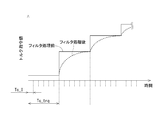
- the calculation cycle Tc_trq of the torque command generator 20 is set longer than the calculation cycle Tc_I of the current controller 30. Therefore, the calculated torque command is input stepwise to the current controller 30 that calculates with a relatively short period. Further, the responsiveness (current control calculation cycle) of the current controller 30 is faster than the torque command calculation cycle. Therefore, when the current controller 30 uses the input from the torque command generator 20 (input torque command) as it is for control, the actual torque is output from the MG 80 stepwise. As a result, for example, when applied to a hybrid vehicle, drivability may be affected.
- Patent Document 1 Japanese Patent No. 3809788 discloses a technique for extracting high-order components using a high-pass filter or a current response model.
- a high-pass filter is used, there remains a problem such as residual fundamental wave components.
- the current response model is used, the calculation load increases by the filter calculation process.
- a high-order component is calculated from the difference between the current command values Id * and Iq * generated from the torque command value Trq * _f after the filter processing by the command value filter 11 and the actual currents Id and Iq. Extract.
- the MG control apparatus 10 according to the present embodiment can avoid problems such as remaining fundamental wave components when a high-pass filter is used.
- the MG control device 10 according to the present embodiment can appropriately extract higher-order components without increasing the calculation load as in the case of using the current response model. As a result, the MG control device 10 according to the present embodiment can shorten the processing time.
- the d-axis voltage command value is calculated from the q-axis current deviation
- the q-axis voltage command value is calculated from the d-axis current deviation.
- the vector is rotated to correct the phase of the higher-order voltage vector such as the fifth order and the seventh order and the phase of the current vector.
- This high-order vector conversion process is executed for the high-order current vector deviation input to the fifth voltage command calculation unit 55 and the seventh voltage command calculation unit 75.
- the high-order vector conversion process is executed on the high-order voltage command vector calculated by feedback control.
- FIG. 8B illustrates a case where only rotation transformation (R) is performed in the high-order vector transformation processing.
- FIG. 8C illustrates a case where rotation conversion (R) and amplitude conversion (G) are simultaneously performed in the high-order vector conversion process.
- the rotation angle ⁇ k generally indicates rotational transformation for a k-th order vector.
- the fifth voltage command vectors Vd 5 * and Vq 5 * calculated by the fifth voltage command calculation unit 55 and the seventh order calculated by the seventh voltage command calculation unit 75 are used.
- the voltage command vectors Vd 7 * and Vq 7 * are rotated.
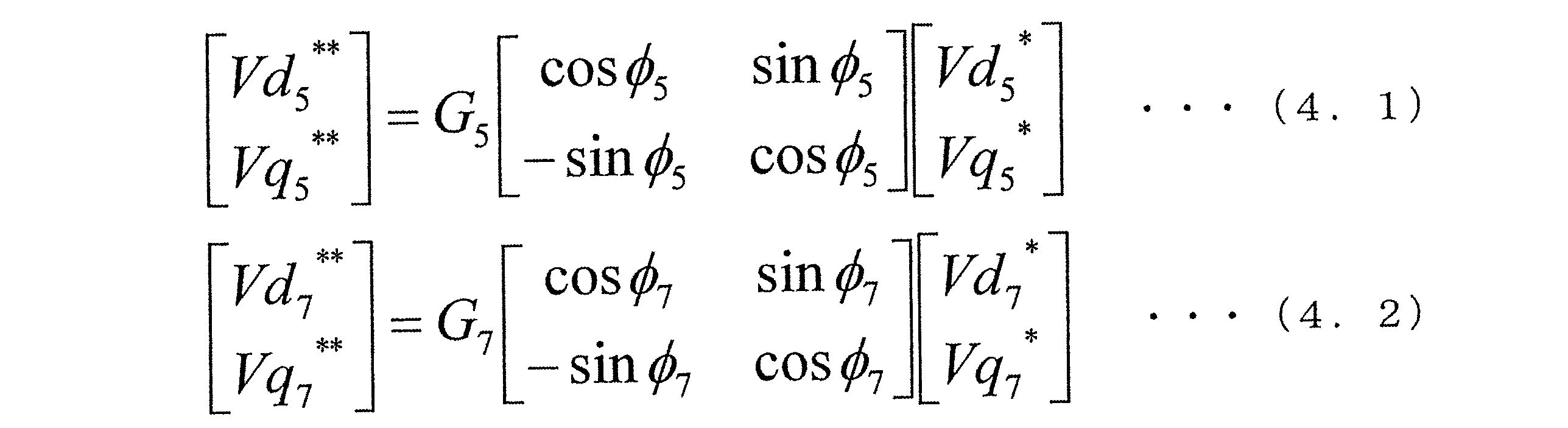
- the high-order vector conversion processing by the fifth-order voltage vector conversion unit 57 and the seventh-order voltage vector conversion unit 77 is expressed by Expression (4.1) and Expression (4.2) each including a rotation matrix.
- the phase difference ⁇ between the voltage vector and the current vector is caused by the inductance of the MG 80 and the induced voltage of the rotor. Therefore, the phase difference ⁇ depends on the operating state such as the current value and the rotational speed.
- the conversion amount setting units 56 and 76 according to the present embodiment map, for example, the relationship between the fundamental wave current command values Id * and Iq * and the rotation speed ⁇ , the phase difference ⁇ , and the amplitude ratio that are measured in advance. (Association data) is stored in advance.
- the high-order voltage command vectors Vd 5 * , Vq 5 * , Vd 7 * , and Vq 7 * are high-order vectors so that the phases of the high-order voltage vector and the high-order current vector coincide with each other. Perform the conversion process. Thereby, the MG control apparatus 10 according to the present embodiment can stabilize the motor control. The same applies to the case where high-order vector conversion processing is performed on the high-order current vector deviations ⁇ Id 5 , ⁇ Iq 5 , ⁇ Id 7 , ⁇ Iq 7 input to the fifth-order voltage command computation unit 55 and the seventh-order voltage command computation unit 75. It is.
- the rotation angles ⁇ 5 and ⁇ 7 of the rotation conversion and the gains G 5 and G 7 of the amplitude conversion are set according to the operation state such as the current value and the rotation speed.
- a current controller may not include a command value filter.
- a command value filter For example, when the processing capacity of the MG control apparatus has a margin, higher-order components may be extracted using a current response model.
- the torque command value Trq * input to the current controller may not include a high frequency component. In that case, a high-order component can be appropriately extracted from the difference between the current command values Id * and Iq * generated from the torque command value Trq * not including the high-frequency component and the actual currents Id and Iq.
- the AC motor driven in the system to which the technology of the present disclosure is applied may not have a function as a generator, like the MG 80 according to the above embodiment. Further, the AC motor is not limited to a permanent magnet type synchronous motor, and may be an induction motor or other synchronous motor.
- the number of phases of the rotating machine of the multiphase AC motor may be four or more. The specific order of the higher-order component to be extracted from the actual current differs depending on the number of phases.
- the control apparatus for an AC motor in the present disclosure is not limited to an MG drive system for a hybrid vehicle or an electric vehicle, but may be applied to an AC motor drive system for any application, such as for general machines.
- the present disclosure is not limited to the embodiment described above, and can be implemented in various forms without departing from the spirit of the disclosed technology.
- MG control device control device for AC motor
- 40 Inverter, 41-46... Switching element, 55, 75 ... 5th / 7th voltage command calculation unit (higher order voltage command calculation unit), 56, 76 ... conversion amount setting section, 57, 77... 5th / 7th voltage vector converter (higher order vector converter), 80: MG (AC motor).
Landscapes
- Engineering & Computer Science (AREA)
- Power Engineering (AREA)
- Control Of Ac Motors In General (AREA)
Abstract
電流制御器(30)は、基本波電流制御及び高次電流制御により、インバータ(40)を駆動する駆動信号を演算する。5次/7次電圧指令演算部(55,75)は、実電流から抽出された5次及び7次成分の高次dq変換値を、5次及び7次dq軸電流指令値Idk
*,Iqk
*(以下、k=5、7)に一致させるフィードバック制御により、5次/7次電圧指令ベクトルVdk
*,Vqk
*を演算する。5次/7次ベクトル変換部(57,77)は、5次/7次電圧指令演算部により演算された5次/7次電圧指令ベクトルVdk
*,Vqk
*に対して、高次dq座標上における高次電圧ベクトルと高次電流ベクトルとの位相を一致させるように、高次ベクトルを回転させる回転変換を含む高次ベクトル変換処理を実行する。
Description
本開示は、電流フィードバック制御により多相交流電動機の通電を制御する交流電動機の制御技術に関する。
多相交流電動機は、ベクトル制御において、交流電動機を構成するロータマグネットの着磁不均一性やロータ及びステータの形状に起因して、相電流の基本波成分に高次成分が重畳されることが知られている。例えば特許文献1に開示されたモータ制御装置は、実電流の高次成分を高次dq変換により直流化し、0に設定された高次電流指令値に対してフィードバック制御している。
特許文献1の「第1の実施の形態」に開示されたモータ制御装置は、高次dq軸電流制御部が、高次dq軸の実電流idh,iqhを電流指令値idh*=0,iqh*=0に一致させるための高次dq軸電圧指令値vdh*,vqh*を演算する。具体的な制御構成は示されていないが、高次dq軸電流制御部は、基本波電流制御と同様に、d軸,q軸それぞれに対して比例積分演算を行いフィードバック制御をしていると推測される。
しかし一般に、dq軸座標上における電圧ベクトルと電流ベクトルとの位相は一致せず、位相差が存在する。この位相差が大きくなると、交流電動機の構造や特性によっては、モータ制御が不安定になる場合がある。
しかし一般に、dq軸座標上における電圧ベクトルと電流ベクトルとの位相は一致せず、位相差が存在する。この位相差が大きくなると、交流電動機の構造や特性によっては、モータ制御が不安定になる場合がある。
本開示は、高次電圧ベクトルと高次電流ベクトルとの位相を一致させ、制御を安定させる交流電動機の制御技術を提供することを目的とする。
本開示の技術の一態様である交流電動機の制御装置は、複数のスイッチング素子(41-46)の動作により変換した電力を多相の交流電動機(80)に供給するインバータ(40)と、交流電動機の通電を制御する電流制御器(30)と、を備える。
電流制御器は、「基本波電流制御」及び「高次電流制御」により、インバータを駆動する駆動信号を演算する。「基本波電流制御」は、フィードバックされた実電流の1次成分を、dq座標上において基本波電流指令ベクトルに一致させる制御である。「高次電流制御」は、フィードバックされた実電流から抽出された1つ以上の特定次数の高次成分を、高次dq座標上において高次電流指令ベクトルに一致させる制御である。
電流制御器は、「基本波電流制御」及び「高次電流制御」により、インバータを駆動する駆動信号を演算する。「基本波電流制御」は、フィードバックされた実電流の1次成分を、dq座標上において基本波電流指令ベクトルに一致させる制御である。「高次電流制御」は、フィードバックされた実電流から抽出された1つ以上の特定次数の高次成分を、高次dq座標上において高次電流指令ベクトルに一致させる制御である。
電流制御器は、高次電圧指令演算部(55,75)、及び、高次ベクトル変換部(57,77)を有する。
高次電圧指令演算部は、実電流から抽出された特定次数の高次成分の高次dq変換値を、高次dq軸電流指令値に一致させるフィードバック制御により、高次電圧指令ベクトルを演算する。
高次電圧指令演算部は、実電流から抽出された特定次数の高次成分の高次dq変換値を、高次dq軸電流指令値に一致させるフィードバック制御により、高次電圧指令ベクトルを演算する。
高次ベクトル変換部は、高次ベクトルを回転させる「回転変換」を含む「高次ベクトル変換処理」を実行する。具体的には、高次ベクトル変換部は、高次電圧指令演算部に入力される高次電流ベクトル偏差、又は、高次電圧指令演算部により演算された高次電圧指令ベクトルに対して、高次dq座標上における高次電圧ベクトルと高次電流ベクトルとの位相を一致させるように、高次ベクトルを回転させる。
このように、高次ベクトル変換部は、高次電流ベクトル偏差又は高次電圧指令ベクトルに対して、高次ベクトル変換処理を実行する。これにより、本開示の制御装置は、モータ制御を安定させられる。
このように、高次ベクトル変換部は、高次電流ベクトル偏差又は高次電圧指令ベクトルに対して、高次ベクトル変換処理を実行する。これにより、本開示の制御装置は、モータ制御を安定させられる。
なお、高次ベクトル変換処理は、回転変換に加え、高次ベクトルの振幅に1倍以外のゲインを乗ずる「振幅変換」を含んでいてもよい。
また、電流制御器は、基本波電流指令値及び交流電動機の回転数に応じて、高次ベクトル変換処理における変換量である、回転変換の回転角及び振幅変換のゲインを設定する変換量設定部(56,76)をさらに有する。
このように、電流制御器は、電流値や回転数等の交流電動機の動作状態に応じて、回転変換の回転角及び振幅変換のゲインを設定する。これにより、本開示の制御装置は、フィードバック制御の応答性を動作点によらず一定にできる。
また、電流制御器は、基本波電流指令値及び交流電動機の回転数に応じて、高次ベクトル変換処理における変換量である、回転変換の回転角及び振幅変換のゲインを設定する変換量設定部(56,76)をさらに有する。
このように、電流制御器は、電流値や回転数等の交流電動機の動作状態に応じて、回転変換の回転角及び振幅変換のゲインを設定する。これにより、本開示の制御装置は、フィードバック制御の応答性を動作点によらず一定にできる。
以下、本開示の技術の一態様である交流電動機の制御装置の実施形態を図面に基づいて説明する。実施形態に係る交流電動機の制御装置は、ハイブリッド自動車や電気自動車の動力源であるモータジェネレータ(以下「MG」という)を駆動するシステム(以下「MG駆動システム」という)において、三相交流モータであるMGの通電を制御する。なお、実施形態に係る「MG」及び「MG制御装置」は、請求の範囲に記載の「多相の交流電動機」及び「交流電動機の制御装置」に相当する。
(第1実施形態)
[システム構成]
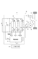
本実施形態に係るMG駆動システム全体の構成について図1を参照して説明する。図1には、1つのMGを備えるシステムを例示する。ハイブリッド自動車に搭載されるMG駆動システム99は、充放電可能な二次電池であるバッテリ25の直流電力を、インバータ40により三相交流電力に変換する。MG駆動システム99は、三相交流電力をMG80に供給し、MG80を駆動する。MG駆動システム99のMG制御装置10は、電流制御器30及びインバータ40を備える。
なお、本実施形態に係るMG制御装置10は、2つ以上のMGを備えるMG駆動システムにも適用可能である。
[システム構成]
本実施形態に係るMG駆動システム全体の構成について図1を参照して説明する。図1には、1つのMGを備えるシステムを例示する。ハイブリッド自動車に搭載されるMG駆動システム99は、充放電可能な二次電池であるバッテリ25の直流電力を、インバータ40により三相交流電力に変換する。MG駆動システム99は、三相交流電力をMG80に供給し、MG80を駆動する。MG駆動システム99のMG制御装置10は、電流制御器30及びインバータ40を備える。
なお、本実施形態に係るMG制御装置10は、2つ以上のMGを備えるMG駆動システムにも適用可能である。
インバータ40は、上下アームの6つのスイッチング素子41-46がブリッジ接続されている。具体的には、スイッチング素子41,42,43は、それぞれU相,V相,W相の上アームのスイッチング素子である。スイッチング素子44,45,46は、それぞれU相,V相,W相の下アームのスイッチング素子である。スイッチング素子41-46は、例えばIGBT(Insulated Gate Bipolar Transistor)で構成され、低電位側から高電位側へ向かう電流を許容する還流ダイオードが並列に接続されている。
インバータ40は、電流制御器30からのPWM信号UU,UL,VU,VL,WU,WLに従って、スイッチング素子41-46が動作することによって、直流電力を三相交流電力に変換する。インバータ40は、電流制御器30が演算した電圧指令に応じた相電圧Vu,Vv,Vwを、MG80の各相巻線81,82,83に印加する。
インバータ40の入力部には、入力電圧を平滑化する平滑コンデンサ47が設けられている。入力電圧センサ48は、インバータ入力電圧Vinvを検出する。なお、バッテリ25とインバータ40との間には、昇圧コンバータを備えてもよい。
インバータ40の入力部には、入力電圧を平滑化する平滑コンデンサ47が設けられている。入力電圧センサ48は、インバータ入力電圧Vinvを検出する。なお、バッテリ25とインバータ40との間には、昇圧コンバータを備えてもよい。
MG80は、例えば永久磁石式同期型の三相交流モータである。本実施形態では、MG80はエンジン91を備えたハイブリッド自動車に搭載される。MG80は、電動機としての機能と発電機としての機能とを兼ね備える。具体的には、MG80は、駆動輪95を駆動するトルクを発生する電動機としての機能を有する。MG80は、エンジン91や駆動輪95から伝達されるトルクを発電によってエネルギー回収する発電機としての機能を有する。また、MG80は、例えば変速機等のギア93を介して車軸94に接続されている。MG80が発生したトルクは、ギア93を介して車軸94を回転させる。これにより、駆動輪95は駆動する。
MG80の三相巻線81,82,83のうち、二相の巻線に接続される電流経路には、相電流を検出する電流センサが設けられる。図1の例に示す本実施形態では、V相巻線82及びW相巻線83に接続される電流経路に、それぞれ相電流Iv,Iwを検出する電流センサ62,63が設けられている。これにより、本実施形態では、U相の電流Iuをキルヒホッフの法則に基づいて推定している。なお、電流検出方法はどの二相の電流を検出してもよい。他の方法としては三相の電流を検出してもよい。或いは、一相の電流検出値に基づいて他の二相の電流を推定する技術を採用してもよい。
MG80のロータ位置に応じた電気角θeは、例えばレゾルバ等の位置センサ85により検出される。
MG80のロータ位置に応じた電気角θeは、例えばレゾルバ等の位置センサ85により検出される。
トルク指令生成器20は、MG80のトルク指令値Trq*を生成する。本実施形態では、各種入力信号に基づき車両の運転状態を総合的に判断し、車両の駆動を制御する車両制御回路のうち、トルク指令生成の機能部のみを示す。なお、本実施形態では、車両制御回路の他の機能部、バッテリ25やエンジン91に係る制御回路等の図示及び説明を省略する。
電流制御器30は、上記各センサが検出したインバータ入力電圧Vinv、相電流Iv,Iw、電気角θeを取得する。また、電流制御器30には、上位制御回路であるトルク指令生成器20からトルク指令値Trq*が入力される。電流制御器30は、これらの情報に基づいて、インバータ40を駆動する駆動信号として、PWM信号UU,UL,VU,VL,WU,WLを演算する。インバータ40は、PWM信号UU,UL,VU,VL,WU,WLに従って、スイッチング素子41-46が動作することにより電力を変換する。そして、インバータ40は、電流制御器30の指令に応じた電力をMG80に出力する。
なお、インバータ40を駆動する駆動信号は、PWM信号に限らない。駆動信号は、例えばパルスパターン等による信号を用いてもよい。ただし、MG80へ通電される電流には、高次成分ができる限り含まれないようにすることが好ましい。
なお、インバータ40を駆動する駆動信号は、PWM信号に限らない。駆動信号は、例えばパルスパターン等による信号を用いてもよい。ただし、MG80へ通電される電流には、高次成分ができる限り含まれないようにすることが好ましい。
ところで、MG80の通電制御では、MG80を構成するロータマグネットの着磁不均一性やロータ及びステータの形状等に起因して、相電流の基本波成分に高次成分が重畳される。その結果、損失やNV特性(騒音及び振動の特性)は、基本波に対する高次成分の比率に応じて影響を受ける。
特に損失やNV特性に関する要求の厳しいハイブリッド自動車等のMG駆動システム99では、特定次数の高次電流を所望の値に制御することが求められる。ここでいう所望の値は、車両の運転状況が反映される動作点や車両の要求特性等に応じて、0であることが求められる場合がある。また、所望の値は、0以外の所定値に設定されることが好ましい場合もある。
特に損失やNV特性に関する要求の厳しいハイブリッド自動車等のMG駆動システム99では、特定次数の高次電流を所望の値に制御することが求められる。ここでいう所望の値は、車両の運転状況が反映される動作点や車両の要求特性等に応じて、0であることが求められる場合がある。また、所望の値は、0以外の所定値に設定されることが好ましい場合もある。
特許文献1(特許第3809783号公報)には、実電流の高次成分を高次dq変換により直流化し、0に設定された高次電流指令値に対してフィードバック制御するモータ制御装置が開示されている。
本実施形態に係るMG制御装置10は、特許文献1の開示技術における問題点を解決するための電流制御器30を備える。以下、本実施形態に係る電流制御器30の構成について詳しく説明する。
本実施形態に係るMG制御装置10は、特許文献1の開示技術における問題点を解決するための電流制御器30を備える。以下、本実施形態に係る電流制御器30の構成について詳しく説明する。
[電流制御器の構成、作用]
本実施形態に係る電流制御器30の構成及び作用について図2~図8を参照して説明する。
電流制御器30は、マイクロコンピュータ等により構成され、CPU、ROM、I/O、及び、これらを接続するバスライン等を備えている。電流制御器30は、ROM等に予め記憶されているプログラムをCPUが実行することによる制御(ソフトウェア処理による制御)や、専用の電子回路による制御(ハードウェア処理による制御)を実行する。
本実施形態に係る電流制御器30の構成及び作用について図2~図8を参照して説明する。
電流制御器30は、マイクロコンピュータ等により構成され、CPU、ROM、I/O、及び、これらを接続するバスライン等を備えている。電流制御器30は、ROM等に予め記憶されているプログラムをCPUが実行することによる制御(ソフトウェア処理による制御)や、専用の電子回路による制御(ハードウェア処理による制御)を実行する。
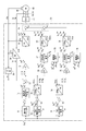
図2には、電流制御器30の制御ブロックを例示する。電流制御器30は、基本波電流制御系の制御ブロックと高次電流制御系の制御ブロックとを有する。「基本波電流制御」は、フィードバックされた実電流の1次成分をdq座標上において基本波電流指令ベクトルに一致させる制御である。「高次電流制御」は、フィードバックされた実電流から抽出された1つ以上の特定次数の高次成分を、高次dq座標上において高次電流指令ベクトルに一致させる制御である。
駆動対象が三相交流モータである本実施形態では、特定次数として5次及び7次の例を示す。したがって、高次電流制御系の制御ブロックは、さらに、5次電流制御系と7次電流制御系との各制御ブロックに分けられる。なお、相電流5次成分は、相電流1次成分に対し5倍の周波数を有する成分である。相電流7次成分は、相電流1次成分に対し7倍の周波数を有する成分である。
各制御ブロックの参照符号には、2桁数字を用いている。具体的には、参照符号は、2桁数字の2桁目を、基本波電流制御系では「1」、5次電流制御系では「5」、7次電流制御系では「7」とし、1桁目を互いの付番に対応させる。
その他、電流センサ62,63、及び、位置センサ85からのフィードバック情報を処理する各制御ブロックの参照符号は、2桁数字の2桁目を「3」とする。そのうち、上記各制御系に含まれない微分器38について先に説明する。微分器38は、位置センサ85が検出した電気角θeを時間微分して、電気角速度ω[deg/s]を算出する。電気角速度ωは、比例定数を乗じることにより回転数N[rpm]に換算される。そのため、本明細書では「電気角速度ωを換算した回転数」を省略して「回転数ω」と表現する。
その他、電流センサ62,63、及び、位置センサ85からのフィードバック情報を処理する各制御ブロックの参照符号は、2桁数字の2桁目を「3」とする。そのうち、上記各制御系に含まれない微分器38について先に説明する。微分器38は、位置センサ85が検出した電気角θeを時間微分して、電気角速度ω[deg/s]を算出する。電気角速度ωは、比例定数を乗じることにより回転数N[rpm]に換算される。そのため、本明細書では「電気角速度ωを換算した回転数」を省略して「回転数ω」と表現する。
以下、各制御ブロックについて、全体の概要を説明した後、特徴部分について詳しく説明する。
まず、基本波電流制御に関する構成を説明する。
基本波電流制御系の制御ブロックは、指令値フィルタ11、基本波電流指令生成部12、基本波電流偏差算出部13、基本波電圧指令演算部15、三相変換部18、高次電圧成分重畳部19、及び、実電流dq変換部36を有する。
まず、基本波電流制御に関する構成を説明する。
基本波電流制御系の制御ブロックは、指令値フィルタ11、基本波電流指令生成部12、基本波電流偏差算出部13、基本波電圧指令演算部15、三相変換部18、高次電圧成分重畳部19、及び、実電流dq変換部36を有する。
指令値フィルタ11は、一次遅れフィルタである。指令値フィルタ11は、トルク指令生成器20から取得したトルク指令値Trq*をフィルタ処理する。フィルタ処理の技術的意義については、詳しくは後述する。
基本波電流指令生成部12は、指令値フィルタ11により処理されたフィルタ処理後のトルク指令値Trq*_fに基づいて、dq座標における基本波電流指令値Id*,Iq*を生成する。電流指令値生成処理は、例えば記録媒体に予め記憶されているマップ(対応付けデータ)を参照することにより行ってもよく、所定の数式等を用いて演算してもよい。5次及び7次の各高次電流指令生成処理についても同様である。
基本波電流指令生成部12は、指令値フィルタ11により処理されたフィルタ処理後のトルク指令値Trq*_fに基づいて、dq座標における基本波電流指令値Id*,Iq*を生成する。電流指令値生成処理は、例えば記録媒体に予め記憶されているマップ(対応付けデータ)を参照することにより行ってもよく、所定の数式等を用いて演算してもよい。5次及び7次の各高次電流指令生成処理についても同様である。
以下、dq軸座標における電流又は電圧については、「電流値又は電圧値」と表現する場合と、「電流ベクトル又は電圧ベクトル」と表現する場合とがある。原則として、「値」と表現する場合は、スカラー量であるd軸電流値(又は電圧値)、及び、スカラー量であるq軸電流値(又は電圧値)それぞれに着目する。一方、「ベクトル」と表現する場合は、座標上において振幅及び位相が規定されているベクトルとして着目する。特に高次電流制御における高次ベクトル変換処理では、位相について言及するため「ベクトル」を用いる。
本来、ベクトル制御を根幹とする電流制御器30の説明では、全てのdq軸電流又はdq軸電圧について、「ベクトル」を用いてよいとも考えられる。しかし、本明細書では、記載が冗長になることを避けるため、明らかに「ベクトル」を用いる方が適当である場合以外は「値」を用いることとする。
本来、ベクトル制御を根幹とする電流制御器30の説明では、全てのdq軸電流又はdq軸電圧について、「ベクトル」を用いてよいとも考えられる。しかし、本明細書では、記載が冗長になることを避けるため、明らかに「ベクトル」を用いる方が適当である場合以外は「値」を用いることとする。
実電流dq変換部36は、位置センサ85が検出した電気角θeに基づいて、電流センサ62,63が検出した固定座標系の相電流Iv,Iwを回転座標系のdq軸電流Id,Iqに座標変換する。このdq軸電流Id,Iqは、MG80に実際に通電されている実電流として、基本波電流偏差算出部13にフィードバックされる。
ここで、相電流Iv,Iwは、相電流1次成分に対して、相電流5次成分や相電流7次成分等の高次成分が重畳している。厳密には、5次及び7次の他、11次、13次、17次、19次等の(6n±1)次成分(nは自然数)が重畳している可能性がある。本実施形態では、説明を分かりやすくするために、11次以上の成分を省略し、相電流5次成分及び相電流7次成分についてのみ言及する。この相電流5次成分及び相電流7次成分は、dq変換によりdq軸電流6次成分に変換される。
なお、後述の説明では、負の次数を定義し、「相電流(-5)次」、「dq軸(-6)次」等の言い方を用いる。一方ここでは、次数の正負を区別せず、絶対値で表す。
なお、後述の説明では、負の次数を定義し、「相電流(-5)次」、「dq軸(-6)次」等の言い方を用いる。一方ここでは、次数の正負を区別せず、絶対値で表す。
基本波電流偏差算出部13は、基本波電流指令生成部12が生成した基本波電流指令値Id*,Iq*と、実電流dq変換部36からフィードバックされた実電流Id,Iqと、の差分である、基本波電流偏差ΔId,ΔIqを算出する。基本波電流偏差ΔId,ΔIqは、後述のように、dq座標系の6次成分に相当すると考えられる。
基本波電圧指令演算部15は、例えばPI制御器で構成される。基本波電圧指令演算部15は、基本波電流偏差ΔId,ΔIqを、それぞれ0に収束させるように、PI制御演算により基本波のdq軸電圧指令値Vd*,Vq*を演算する。
三相変換部18は、電気角θeに基づいて、基本波のdq軸電圧指令値Vd*,Vq*を三相電圧指令値Vu*,Vv*,Vw*に座標変換する。以下、三相電圧指令値「Vu*,Vv*,Vw*」は、「Vuvw*」と表現する。高次三相電圧指令値についても、同様に「Vuvw5 **,Vuvw7 **」と表現する。
三相変換部18は、電気角θeに基づいて、基本波のdq軸電圧指令値Vd*,Vq*を三相電圧指令値Vu*,Vv*,Vw*に座標変換する。以下、三相電圧指令値「Vu*,Vv*,Vw*」は、「Vuvw*」と表現する。高次三相電圧指令値についても、同様に「Vuvw5 **,Vuvw7 **」と表現する。
高次電圧成分重畳部19は、基本波の三相電圧指令値Vuvw*に、5次及び7次の電流制御系の各制御ブロックにより演算された5次及び7次の三相電圧指令値Vuvw5
**,Vuvw7
**を重畳する。図2では、図示の便宜上、5次の三相電圧指令値Vuvw5
**と、7次の三相電圧指令値Vuvw7
**と、を加算してから、基本波の三相電圧指令値Vuvw*に加算する例が示されている。つまり、図2には、三相電圧指令値が二段階で加算される例が記載している。なお、加算方法については、これに限らない。他の加算方法としては、加算の順序は問わず、一段階で加算してもよい。
図2では、高次電圧成分重畳部19とインバータ40との間の制御ブロックを省略している。この間には、電圧デューティ変換部及びPWM信号生成部が設けられる。
電圧デューティ変換部は、基本波の三相電圧指令値Vuvw*を指令デューティに変換する。この変換の演算では、インバータ入力電圧Vinvの情報が用いられる。PWM信号生成部は、指令デューティに基づくPWM変調により、PWM信号UU,UL,VU,VL,WU,WLを算出し、インバータ40に出力する。なお、PWM制御は周知技術であるため、詳しい説明を省略する。
電圧デューティ変換部は、基本波の三相電圧指令値Vuvw*を指令デューティに変換する。この変換の演算では、インバータ入力電圧Vinvの情報が用いられる。PWM信号生成部は、指令デューティに基づくPWM変調により、PWM信号UU,UL,VU,VL,WU,WLを算出し、インバータ40に出力する。なお、PWM制御は周知技術であるため、詳しい説明を省略する。
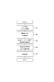
図3には、基本波電流制御系の制御ブロックにより実行される基本波電流制御処理の概略フローを例示する。なお、フローチャートにおける記号「S」は処理工程(ステップ)を意味する。
指令値フィルタ11は、トルク指令フィルタ処理を行う(ステップS1)。
基本波電流指令生成部12は、フィルタ処理後のトルク指令値Trq*_fに基づいて、dq座標における基本波電流指令値Id*,Iq*の生成処理を行う(ステップS2)。
実電流dq変換部36及び基本波電流偏差算出部13は、基本波電流指令値Id*,Iq*に対する電流フィードバック処理を行う。そして、基本波電圧指令演算部15は、基本波のdq軸電圧指令値Vd*,Vq*を演算する(ステップS3)。
三相変換部18は、基本波のdq軸電圧指令値Vd*,Vq*を座標変換し、相電圧算出処理を行う(ステップS4)。
PWM信号生成部は、PWM変調を行う(ステップS5)。
指令値フィルタ11は、トルク指令フィルタ処理を行う(ステップS1)。
基本波電流指令生成部12は、フィルタ処理後のトルク指令値Trq*_fに基づいて、dq座標における基本波電流指令値Id*,Iq*の生成処理を行う(ステップS2)。
実電流dq変換部36及び基本波電流偏差算出部13は、基本波電流指令値Id*,Iq*に対する電流フィードバック処理を行う。そして、基本波電圧指令演算部15は、基本波のdq軸電圧指令値Vd*,Vq*を演算する(ステップS3)。
三相変換部18は、基本波のdq軸電圧指令値Vd*,Vq*を座標変換し、相電圧算出処理を行う(ステップS4)。
PWM信号生成部は、PWM変調を行う(ステップS5)。
続いて、高次電流制御に関する構成を説明する。
5次電流制御系の制御ブロックは、5次電流指令生成部52、5次電流偏差算出部53、5次dq変換部54、5次電圧指令演算部55、変換量設定部56、5次電圧ベクトル変換部57、及び、三相変換部58を有する。
5次電流指令生成部52は、トルク指令値Trq*及びMG80の回転数ωに応じて、マップ(対応付けデータ)の参照等により5次dq軸電流指令値Id5 *,Iq5 *を生成する。上述のように、5次電流を所望の値は、システムに要求される損失やNV特性により、「Id5 *=0,Iq5 *=0」としてもよく、0以外の目標値に設定してもよい。
5次電流制御系の制御ブロックは、5次電流指令生成部52、5次電流偏差算出部53、5次dq変換部54、5次電圧指令演算部55、変換量設定部56、5次電圧ベクトル変換部57、及び、三相変換部58を有する。
5次電流指令生成部52は、トルク指令値Trq*及びMG80の回転数ωに応じて、マップ(対応付けデータ)の参照等により5次dq軸電流指令値Id5 *,Iq5 *を生成する。上述のように、5次電流を所望の値は、システムに要求される損失やNV特性により、「Id5 *=0,Iq5 *=0」としてもよく、0以外の目標値に設定してもよい。
5次dq変換部54は、電気角θeの(-5)倍角である「-5θe」に基づいて、基本波電流偏差ΔId,ΔIq(dq座標系の6次成分)を、高次dq座標系である5次dq座標系に高次dq変換する。これにより、5次dq変換部54は、実電流に含まれる相電流5次成分を抽出する。以下、「5次dq変換」等の次数は、固定座標系の次数の絶対値を用いて表現する。「-5θe」の負の符号の意味は後述する。
5次電流偏差算出部53は、5次電流指令生成部52が生成した5次dq軸電流指令値Id5
*,Iq5
*と、5次dq変換部54により高次dq変換された5次dq変換値と、の差分である、5次電流偏差ΔId5,ΔIq5を算出する。
ここで、基本波電流偏差算出部13からの出力には、実電流Id,Iqをマイナスして算出された値が反映される。したがって、5次dq変換部54から5次電流偏差算出部53への入力は、プラスで表現し、マイナスの量を差し引いている。
ここで、基本波電流偏差算出部13からの出力には、実電流Id,Iqをマイナスして算出された値が反映される。したがって、5次dq変換部54から5次電流偏差算出部53への入力は、プラスで表現し、マイナスの量を差し引いている。
5次電圧指令演算部55は、例えばPI制御器で構成される。5次電圧指令演算部55は、5次電流偏差ΔId5,ΔIq5を、それぞれ0に収束させるように、PI制御演算により5次電圧指令ベクトルVd5
*,Vq5
*を演算する。
5次電圧ベクトル変換部57は、5次電圧指令演算部55が演算した5次電圧指令ベクトルVd5 *,Vq5 *に対し、5次dq座標上において「高次ベクトル変換処理」を実行する。5次電圧ベクトル変換部57は、変換後の5次dq軸電圧指令ベクトルVd5 **,Vq5 **を出力する。
5次電圧ベクトル変換部57は、5次電圧指令演算部55が演算した5次電圧指令ベクトルVd5 *,Vq5 *に対し、5次dq座標上において「高次ベクトル変換処理」を実行する。5次電圧ベクトル変換部57は、変換後の5次dq軸電圧指令ベクトルVd5 **,Vq5 **を出力する。
高次ベクトル変換処理には、5次電圧指令ベクトルVd5
*,Vq5
*の位相を、所定の回転角φ5に従って回転させる「回転変換」が少なくとも含まれる。回転変換の回転角φ5は、2nπ(nは整数)[rad]を除く。
さらに、高次ベクトル変換処理には、5次電圧指令ベクトルVd5 *,Vq5 *の振幅に、1倍以外のゲインG5を乗じる「振幅変換」が含まれてもよい。言い換えれば、高次ベクトル変換処理では、ゲインG5が1倍の場合が、振幅変換を含まない回転変換のみの処理となる。
さらに、高次ベクトル変換処理には、5次電圧指令ベクトルVd5 *,Vq5 *の振幅に、1倍以外のゲインG5を乗じる「振幅変換」が含まれてもよい。言い換えれば、高次ベクトル変換処理では、ゲインG5が1倍の場合が、振幅変換を含まない回転変換のみの処理となる。
高次ベクトル変換処理の変換量である回転変換の回転角φ5、及び、振幅変換のゲインG5は、変換量設定部56により設定される。本実施形態では、変換量設定部56は、基本波電流指令値Id*,Iq*及び回転数ωに応じて、回転変換の回転角φ5、及び、振幅変換のゲインG5を設定する。
高次ベクトル変換処理の技術的意義については、詳しくは後述する。
高次ベクトル変換処理の技術的意義については、詳しくは後述する。
三相変換部58は、電気角θeの(-5)倍角である「-5θe」に基づいて、高次ベクトル変換処理後のdq軸電圧指令値Vd5
**,Vq5
**を、三相電圧指令値Vuvw5
**に座標変換する。5次の三相電圧指令値Vuvw5
**は、高次電圧成分重畳部19によって基本波の三相電圧指令値Vuvw*に重畳される。
7次電流制御系の制御ブロックは、7次電流指令生成部72、7次電流偏差算出部73、7次dq変換部74、7次電圧指令演算部75、変換量設定部76、7次電圧ベクトル変換部77、及び、三相変換部78を有する。各制御ブロックの構成は、5次電流制御系と同様である。特記すべき点として、7次dq変換部74は、電気角θeの7倍角である「7θe」に基づいて、基本波電流偏差ΔId,ΔIqを、7次dq座標系に高次dq変換する。これにより、7次dq変換部74は、実電流に含まれる相電流7次成分を抽出する。その他の点は、5次電流制御系と同様であるため説明を省略する。
次に、本実施形態に係る基本波及び高次電流制御の基礎的事項について図4~図6を参照して説明する。
相電流k次成分について、固定座標系からdq座標系へのdq変換は、式(1)により表される。式(1)中の「φdk」は、dq座標におけるk次成分ベクトルについて、d軸を基準とした位相を示す。また、「Irk」はk次成分の電流ベクトルの振幅を示す。

表1には、式(1)に基づいて、固定座標系における次数とdq座標系における次数との対応関係を示す。
相電流k次成分について、固定座標系からdq座標系へのdq変換は、式(1)により表される。式(1)中の「φdk」は、dq座標におけるk次成分ベクトルについて、d軸を基準とした位相を示す。また、「Irk」はk次成分の電流ベクトルの振幅を示す。
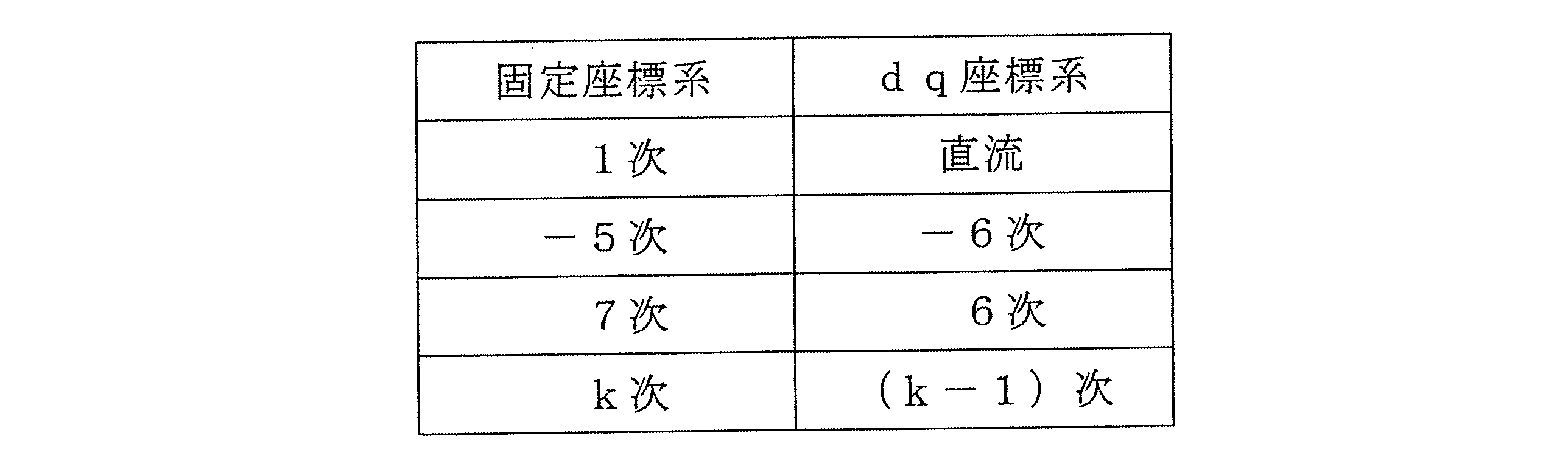
ここで、1次を除く次数kは、式(2.1)により表される。式(2.1)において、n=0の場合が1次(基本波)に相当する。また、n=1の場合が(-5)次及び7次に相当する。
k=1±6n(nは自然数) ・・・(2.1)
さらに、次数の正負を区別しない場合、kの絶対値は、式(2.2)により表される。
|k|=|1±6n|=6n±1(nは自然数) ・・・(2.2)
k=1±6n(nは自然数) ・・・(2.1)
さらに、次数の正負を区別しない場合、kの絶対値は、式(2.2)により表される。
|k|=|1±6n|=6n±1(nは自然数) ・・・(2.2)
表1において負の次数の意味は、次の通りである。
固定座標系において、三相の相順が基本波と逆の場合には次数を負とする。例えば基本波の相順がUVWのときには、相順がUWVとなる高次成分の次数を負で表す。
dq座標系において、高次成分の回転方向が反時計回り(左回り)の場合には次数を正とし、時計回り(右回り)の場合には次数を負とする。
固定座標系において、三相の相順が基本波と逆の場合には次数を負とする。例えば基本波の相順がUVWのときには、相順がUWVとなる高次成分の次数を負で表す。
dq座標系において、高次成分の回転方向が反時計回り(左回り)の場合には次数を正とし、時計回り(右回り)の場合には次数を負とする。
一般には、固定座標系のk次に対しdq座標系の(k-1)次が対応する。具体的には、固定座標系の(-5)次にはdq座標系の(-6)次が対応し、固定座標系の7次にはdq座標系の6次が対応する。よって、相電流(-5)次成分及び相電流7次成分は、三相交流電動機においてトルク6次変動に寄与する。
また、式(1)における「cos(kθe)項」に対応し、図2において5次dq変換部54及び三相変換部58に入力される角度は「-5θe」となる。
また、式(1)における「cos(kθe)項」に対応し、図2において5次dq変換部54及び三相変換部58に入力される角度は「-5θe」となる。
図4には、基本波について、固定座標系とdq座標系との関係を例示する。固定座標系での基本波の相順は、UVWの順とする。
dq軸電流ベクトルの振幅をIr1とすると、相電流の振幅は{√(2/3)}Ir1と表される。また、dq軸電流ベクトルの位相φd1は、固定座標における電気角0°を基準としたとき、例えばU相電流が最大となる位相に相当する。
dq軸電流ベクトルの振幅をIr1とすると、相電流の振幅は{√(2/3)}Ir1と表される。また、dq軸電流ベクトルの位相φd1は、固定座標における電気角0°を基準としたとき、例えばU相電流が最大となる位相に相当する。
図5には、相電流(-5)次成分について、固定座標系と5次dq座標系との関係を例示する。固定座標系の相順は、基本波と逆のUWVであるため、負の次数で表す。
5次dq軸電流ベクトルは、1次dq軸電流ベクトルの終点を中心として電気周期あたり6回、5次座標上を時計回りに回転する。回転半径に相当するdq軸電流ベクトルの振幅をIr5とすると、相電流(-5)次成分の振幅は{√(2/3)}Ir5と表される。
また、5次dq軸電流ベクトルの位相は、「-6θe+φd5」と表される。位相φd5は、固定座標における電気角0°を基準としたとき、例えばU相電流が最大となる位相に相当する。
5次dq軸電流ベクトルは、1次dq軸電流ベクトルの終点を中心として電気周期あたり6回、5次座標上を時計回りに回転する。回転半径に相当するdq軸電流ベクトルの振幅をIr5とすると、相電流(-5)次成分の振幅は{√(2/3)}Ir5と表される。
また、5次dq軸電流ベクトルの位相は、「-6θe+φd5」と表される。位相φd5は、固定座標における電気角0°を基準としたとき、例えばU相電流が最大となる位相に相当する。
相電流に重畳した高次成分は、dq変換後、次数に応じた交流成分としてdq軸電流に現れる。高次dq変換は、相電流に重畳した高次成分を直流化して所望の値に制御する手法である。
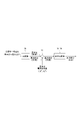
本実施形態では、図6に示すように、固定座標系の相電流を一旦dq座標系に変換した後、高次dq座標系に変換する。図6は、図2に示したdq変換及び高次dq変換に関する制御ブロックを抜粋した図に相当する。なお、説明の都合上、基本波電流偏差算出部13における「+/-」の符号は、図2とは逆に記載する。
本実施形態では、図6に示すように、固定座標系の相電流を一旦dq座標系に変換した後、高次dq座標系に変換する。図6は、図2に示したdq変換及び高次dq変換に関する制御ブロックを抜粋した図に相当する。なお、説明の都合上、基本波電流偏差算出部13における「+/-」の符号は、図2とは逆に記載する。
図6に対応する、「固定座標系→dq座標系→高次dq座標系」の変換式は、式(3)により表される。
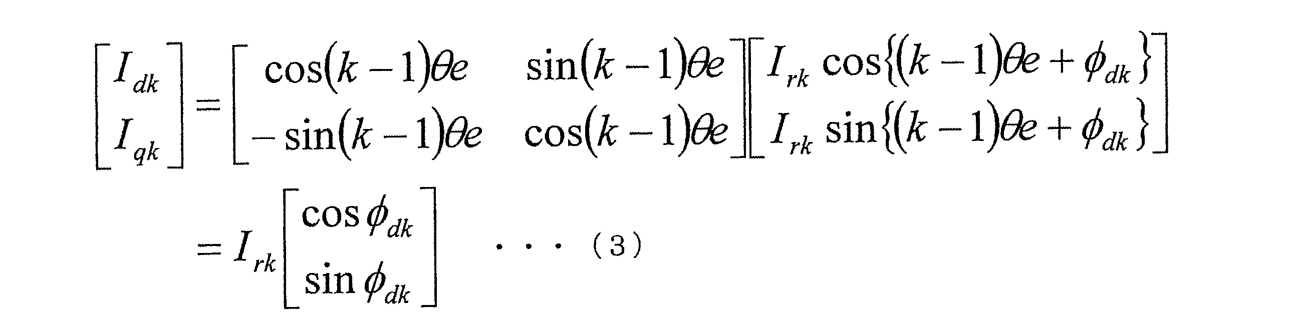
図6において、元信号である相電流には、基本波に高次成分が重畳されている。基本波は、実電流dq変換部36により直流化される。基本波電流偏差算出部13は、dq変換後の実電流から基本波電流指令値Id*,Iq*を除去する。これにより交流の高次成分が残る。高次dq変換部(5次dq変換部、7次dq変換部)54,74では、交流の高次成分を高次dq変換し直流化する。
以上が基本波及び高次電流制御の基礎的事項についての説明である。このように本実施形態では、高次dq変換により特定次数の高次成分を直流化する。これにより、本実施形態に係る電流制御器30は、各次数の高次電流指令値に対してフィードバック制御する。
以上が基本波及び高次電流制御の基礎的事項についての説明である。このように本実施形態では、高次dq変換により特定次数の高次成分を直流化する。これにより、本実施形態に係る電流制御器30は、各次数の高次電流指令値に対してフィードバック制御する。
次に、本実施形態に係る指令値フィルタ11を用いたフィルタ処理の技術的意義について図7A及び図7Bを参照して説明する。
図7Aに示すように、モータ制御では、一般に、トルク指令生成器20の演算周期Tc_trqは電流制御器30の演算周期Tc_Iよりも長く設定される。したがって、演算されたトルク指令は、相対的に短周期で演算する電流制御器30に対してステップ状に入力される。また、電流制御器30の応答性(電流制御の演算周期)は、トルク指令の演算周期と比較して早い。そのため、電流制御器30がトルク指令生成器20からの入力(入力されたトルク指令)をそのまま制御に用いると、MG80からは実トルクが階段状に出力されてしまう。その結果、例えばハイブリッド自動車に適用した場合には、ドライバビリティに影響を及ぼすおそれがある。
図7Aに示すように、モータ制御では、一般に、トルク指令生成器20の演算周期Tc_trqは電流制御器30の演算周期Tc_Iよりも長く設定される。したがって、演算されたトルク指令は、相対的に短周期で演算する電流制御器30に対してステップ状に入力される。また、電流制御器30の応答性(電流制御の演算周期)は、トルク指令の演算周期と比較して早い。そのため、電流制御器30がトルク指令生成器20からの入力(入力されたトルク指令)をそのまま制御に用いると、MG80からは実トルクが階段状に出力されてしまう。その結果、例えばハイブリッド自動車に適用した場合には、ドライバビリティに影響を及ぼすおそれがある。
そこで本実施形態では、電流制御器30の指令値フィルタ11により、トルク指令値Trq*の応答を滑らかにするフィルタ処理を行う。すなわち、本実施形態に係る電流制御器30は、「なまし処理」を行う。
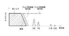
図7Bに示すように、フィルタ処理前のトルク指令値Trq*のスペクトルは、全周波数域にわたって高周波成分を含む。一方、指令値フィルタ11によるフィルタ処理後のトルク指令値Trq*_fのスペクトルは、フィルタ処理前のトルク指令値Trq*に含まれる高周波成分が除去される。電流応答による多少の誤差はあるものの、フィルタ処理後のトルク指令値Trq*_fのスペクトルは、実トルクのスペクトルに近づく。
なお、図7Bには、実トルクのスペクトル範囲のイメージを実線枠で例示し、フィルタ処理後のトルク指令値Trq*_fのスペクトル範囲のイメージを破線枠で例示する。これらの枠は、主なスペクトルが枠内の範囲に存在することを意味する。
図7Bに示すように、フィルタ処理前のトルク指令値Trq*のスペクトルは、全周波数域にわたって高周波成分を含む。一方、指令値フィルタ11によるフィルタ処理後のトルク指令値Trq*_fのスペクトルは、フィルタ処理前のトルク指令値Trq*に含まれる高周波成分が除去される。電流応答による多少の誤差はあるものの、フィルタ処理後のトルク指令値Trq*_fのスペクトルは、実トルクのスペクトルに近づく。
なお、図7Bには、実トルクのスペクトル範囲のイメージを実線枠で例示し、フィルタ処理後のトルク指令値Trq*_fのスペクトル範囲のイメージを破線枠で例示する。これらの枠は、主なスペクトルが枠内の範囲に存在することを意味する。
このように本実施形態では、フィルタ処理後のトルク指令値Trq*_fのスペクトルは、主に1次成分を含み、5次以上の高周波成分を含まない。したがって、本実施形態に係る電流制御器30は、フィルタ処理後のトルク指令値Trq*_fから生成された電流指令値Id*,Iq*を用いて、実電流Id,Iqに含まれる高次成分を抽出できる。
特許文献1(特許第3809783号公報)には、ハイパスフィルタや電流応答モデルを用いて高次成分を抽出する技術が開示されている。しかし、ハイパスフィルタを用いる場合には、基本波成分の残留等が問題となる。また、電流応答モデルを用いる場合には、フィルタ演算処理の分、演算負荷が増加する。
そこで本実施形態では、指令値フィルタ11によるフィルタ処理後のトルク指令値Trq*_fから生成された電流指令値Id*,Iq*と、実電流Id,Iqと、の差分から、高次成分を抽出する。これにより、本実施形態に係るMG制御装置10は、ハイパスフィルタを用いた場合における基本波成分の残留等の問題を回避できる。また、本実施形態に係るMG制御装置10は、電流応答モデルを用いた場合のように演算負荷を増加させることなく、高次成分を適切に抽出できる。その結果、本実施形態に係るMG制御装置10は、処理時間を短縮できる。
次に、本実施形態に係る5次電圧ベクトル変換部57及び7次電圧ベクトル変換部77による高次ベクトル変換処理の技術的意義について図8A~図8Cを参照して説明する。
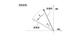
図8Aに示すように、一般に、dq軸座標上における電圧ベクトルと電流ベクトルとの位相は一致せず、位相差Δφが存在する。高次電圧ベクトルと高次電流ベクトルとの位相差Δφが大きくなると、交流電動機の構造や特性によっては、モータ制御が不安定になる場合がある。
図8Aに示すように、一般に、dq軸座標上における電圧ベクトルと電流ベクトルとの位相は一致せず、位相差Δφが存在する。高次電圧ベクトルと高次電流ベクトルとの位相差Δφが大きくなると、交流電動機の構造や特性によっては、モータ制御が不安定になる場合がある。
なお、基本波電流制御では、フィードフォワード項の電圧方程式において、d軸電圧指令値をq軸電流偏差から演算し、q軸電圧指令値をd軸電流偏差から演算する。このように基本波電流制御では、d軸成分とq軸成分とを独立して制御する非干渉制御が知られている。しかし、高次電流制御では、非干渉制御は検討されていない。
そこで本実施形態では、ベクトルを回転させることにより、5次や7次等の高次の電圧ベクトルと電流ベクトルとの位相を一致させる補正を行う。この高次ベクトル変換処理は、5次電圧指令演算部55及び7次電圧指令演算部75に入力される高次電流ベクトル偏差に対して実行される。または、高次ベクトル変換処理は、フィードバック制御により演算された高次電圧指令ベクトルに対して実行される。
そこで本実施形態では、ベクトルを回転させることにより、5次や7次等の高次の電圧ベクトルと電流ベクトルとの位相を一致させる補正を行う。この高次ベクトル変換処理は、5次電圧指令演算部55及び7次電圧指令演算部75に入力される高次電流ベクトル偏差に対して実行される。または、高次ベクトル変換処理は、フィードバック制御により演算された高次電圧指令ベクトルに対して実行される。
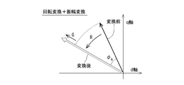
また、高次ベクトル変換処理では、回転変換と同時にベクトルの振幅を変更する振幅変換を行ってもよい。
図8Bには、高次ベクトル変換処理において回転変換(R)のみを行う場合を例示する。図8Cには、高次ベクトル変換処理において回転変換(R)と振幅変換(G)とを同時に行う場合を例示する。なお、回転角φkは、一般にk次のベクトルについての回転変換を示す。
図8Bには、高次ベクトル変換処理において回転変換(R)のみを行う場合を例示する。図8Cには、高次ベクトル変換処理において回転変換(R)と振幅変換(G)とを同時に行う場合を例示する。なお、回転角φkは、一般にk次のベクトルについての回転変換を示す。
図2に示したように、本実施形態では、5次電圧指令演算部55が演算した5次電圧指令ベクトルVd5
*,Vq5
*、及び、7次電圧指令演算部75が演算した7次電圧指令ベクトルVd7
*,Vq7
*を回転させる。5次電圧ベクトル変換部57及び7次電圧ベクトル変換部77による高次ベクトル変換処理は、それぞれ、回転行列を含む式(4.1)及び式(4.2)により表される。
一方、5次電流ベクトル偏差ΔId5,ΔIq5、及び、7次電流ベクトル偏差ΔId7,ΔIq7について、高次ベクトル変換処理を実行する形態では、高次電流ベクトル偏差を回転させてからフィードバック制御する。この形態での電流制御器では、図2に示した構成に対して、制御ブロック「55,75」と「57,77」との配置を入れ替えた構成となる。また、「57,77」の制御ブロックの名称は、「5次/7次電圧ベクトル変換部」に代えて、「5次/7次ベクトル偏差変換部」となる。本開示の技術では、上記2通りの形態によって高次ベクトル変換処理を実行する制御ブロックを包括して、「高次ベクトル変換部」という。
電圧ベクトルと電流ベクトルとの位相差Δφは、MG80のインダクタンスやロータの誘起電圧に起因する。そのため、位相差Δφは、電流値や回転数等の動作状態に依存する。本実施形態に係る変換量設定部56,76は、例えば予め計測しておいた基本波電流指令値Id*,Iq*及び回転数ωと、位相差Δφ及び振幅比率と、の関係を、マップ(対応付けデータ)として予め記憶している。そして、変換量設定部56,76は、基本波電流指令値Id*,Iq*及び回転数ωに応じて、マップの参照等により、高次ベクトル変換処理の変換量である回転変換の回転角φ5,φ7、及び、振幅変換のゲインG5,G7を設定する。
なお、変換量設定部56,76は、基本波電流指令値Id*,Iq*に代えて、実電流Id,IqやMG80のトルク検出値等を、マップ参照時のパラメータとして用いてもよい。
なお、変換量設定部56,76は、基本波電流指令値Id*,Iq*に代えて、実電流Id,IqやMG80のトルク検出値等を、マップ参照時のパラメータとして用いてもよい。
このように本実施形態では、高次電圧指令ベクトルVd5
*,Vq5
*,Vd7
*,Vq7
*について、高次電圧ベクトルと高次電流ベクトルとの位相が一致するように高次ベクトル変換処理を行う。これにより、本実施形態に係るMG制御装置10は、モータ制御を安定させられる。これは、5次電圧指令演算部55及び7次電圧指令演算部75に入力される高次電流ベクトル偏差ΔId5,ΔIq5,ΔId7,ΔIq7について、高次ベクトル変換処理を行う場合も同様である。
また、本実施形態では、電流値や回転数等の動作状態に応じて、回転変換の回転角φ5,φ7、及び、振幅変換のゲインG5,G7を設定する。これにより、本実施形態に係るMG制御装置10は、フィードバック制御の応答性を動作点によらず一定にできる。
また、本実施形態では、電流値や回転数等の動作状態に応じて、回転変換の回転角φ5,φ7、及び、振幅変換のゲインG5,G7を設定する。これにより、本実施形態に係るMG制御装置10は、フィードバック制御の応答性を動作点によらず一定にできる。
(その他の実施形態)
(a)他の実施形態に係る電流制御器は、指令値フィルタを備えなくてよい。例えば、MG制御装置の処理能力に余裕がある場合には、電流応答モデルを用いて高次成分を抽出してもよい。また、トルク指令生成器の演算周期が電流制御器の演算周期と同等のシステムでは、電流制御器に入力されるトルク指令値Trq*は、高周波成分を含まない可能性がある。その場合には、高周波成分を含まないトルク指令値Trq*から生成された電流指令値Id*,Iq*と、実電流Id,Iqと、の差分から、高次成分を適切に抽出できる。
(a)他の実施形態に係る電流制御器は、指令値フィルタを備えなくてよい。例えば、MG制御装置の処理能力に余裕がある場合には、電流応答モデルを用いて高次成分を抽出してもよい。また、トルク指令生成器の演算周期が電流制御器の演算周期と同等のシステムでは、電流制御器に入力されるトルク指令値Trq*は、高周波成分を含まない可能性がある。その場合には、高周波成分を含まないトルク指令値Trq*から生成された電流指令値Id*,Iq*と、実電流Id,Iqと、の差分から、高次成分を適切に抽出できる。
(b)上記実施形態では、三相交流モータであるMG80の駆動システムに適用されるMG制御装置10において、電流制御器30は、絶対値で表した特定次数として5次及び7次成分を制御する。他の実施形態では、電流制御器は、式(2.2)におけるn=2,3・・・の場合に対応する11次、13次、17次、19次等の各次数成分を制御してもよい。
(c)本開示の技術が適用されるシステムにおいて駆動される交流電動機は、上記実施形態に係るMG80のように、発電機としての機能を併せ持つものでなくてもよい。また、交流電動機は、永久磁石式同期型モータに限らず、誘導電動機やその他の同期モータであってもよい。多相交流モータの回転機の相数は、四相以上であってもよい。実電流からの抽出対象となる高次成分の特定次数は、相数に応じて異なる。
(d)本開示における交流電動機の制御装置は、ハイブリッド自動車や電気自動車のMG駆動システムに限らず、一般機械用等、どのような用途の交流電動機の駆動システムに適用されてもよい。
以上、本開示におけるは、上記実施形態に限定されるものではなく、開示技術の趣旨を逸脱しない範囲において、種々の形態により実施可能である。
以上、本開示におけるは、上記実施形態に限定されるものではなく、開示技術の趣旨を逸脱しない範囲において、種々の形態により実施可能である。
100・・・MG制御装置(交流電動機の制御装置)、
30・・・電流制御器、
40・・・インバータ、
41-46・・・スイッチング素子、
55,75・・・5次/7次電圧指令演算部(高次電圧指令演算部)、
56,76・・・変換量設定部、
57,77・・・5次/7次電圧ベクトル変換部(高次ベクトル変換部)、
80・・・MG(交流電動機)。
30・・・電流制御器、
40・・・インバータ、
41-46・・・スイッチング素子、
55,75・・・5次/7次電圧指令演算部(高次電圧指令演算部)、
56,76・・・変換量設定部、
57,77・・・5次/7次電圧ベクトル変換部(高次ベクトル変換部)、
80・・・MG(交流電動機)。
Claims (5)
- 複数のスイッチング素子(41-46)の動作により変換した電力を多相の交流電動機(80)に供給するインバータ(40)と、
フィードバックされた実電流の1次成分をdq座標上において基本波電流指令ベクトルに一致させる基本波電流制御、及び、フィードバックされた前記実電流から抽出された1つ以上の特定次数の高次成分を、高次dq座標上において高次電流指令ベクトルに一致させる高次電流制御により、前記インバータを駆動する駆動信号を演算し、前記交流電動機の通電を制御する電流制御器(30)と、
を備え、
前記電流制御器は、
前記実電流から抽出された前記特定次数の高次成分の高次dq変換値を、高次dq軸電流指令値に一致させるフィードバック制御により、高次電圧指令ベクトルを演算する高次電圧指令演算部(55,75)、及び、
前記高次電圧指令演算部に入力される高次電流ベクトル偏差、又は、前記高次電圧指令演算部により演算された前記高次電圧指令ベクトルに対して、高次dq座標上における高次電圧ベクトルと高次電流ベクトルとの位相を一致させるように、高次ベクトルを回転させる回転変換を含む高次ベクトル変換処理を実行する高次ベクトル変換部(57,77)を有する、交流電動機の制御装置。 - 前記電流制御器は、
基本波電流指令値及び前記交流電動機の回転数に応じて、前記高次ベクトル変換処理における変換量である前記回転変換の回転角を設定する変換量設定部(56、76)を有する、請求項1に記載の交流電動機の制御装置。 - 前記高次ベクトル変換処理は、前記回転変換に加え、前記高次ベクトルの振幅に1倍以外のゲインを乗ずる振幅変換を含む、請求項1に記載の交流電動機の制御装置。
- 前記電流制御器は、
基本波電流指令値及び前記交流電動機の回転数に応じて、前記高次ベクトル変換処理における変換量である、前記回転変換の回転角及び前記振幅変換のゲインを設定する変換量設定部(56,76)を有する、請求項3に記載の交流電動機の制御装置。 - 前記多相の交流電動機は、三相交流電動機であり、
前記電流制御器は、前記特定次数の高次成分として、(6n±1)次(nは自然数)の高次成分を抽出する、請求項1乃至4のいずれか一項に記載の交流電動機の制御装置。
Priority Applications (2)
| Application Number | Priority Date | Filing Date | Title |
|---|---|---|---|
| CN201780012997.4A CN108702117B (zh) | 2016-02-24 | 2017-02-22 | 交流电动机的控制装置 |
| US16/079,727 US10432123B2 (en) | 2016-02-24 | 2017-02-22 | Control apparatus for AC motor |
Applications Claiming Priority (2)
| Application Number | Priority Date | Filing Date | Title |
|---|---|---|---|
| JP2016-032899 | 2016-02-24 | ||
| JP2016032899A JP6540538B2 (ja) | 2016-02-24 | 2016-02-24 | 交流電動機の制御装置 |
Publications (1)
| Publication Number | Publication Date |
|---|---|
| WO2017146090A1 true WO2017146090A1 (ja) | 2017-08-31 |
Family
ID=59685256
Family Applications (1)
| Application Number | Title | Priority Date | Filing Date |
|---|---|---|---|
| PCT/JP2017/006560 Ceased WO2017146090A1 (ja) | 2016-02-24 | 2017-02-22 | 交流電動機の制御装置 |
Country Status (4)
| Country | Link |
|---|---|
| US (1) | US10432123B2 (ja) |
| JP (1) | JP6540538B2 (ja) |
| CN (1) | CN108702117B (ja) |
| WO (1) | WO2017146090A1 (ja) |
Cited By (2)
| Publication number | Priority date | Publication date | Assignee | Title |
|---|---|---|---|---|
| CN111049439A (zh) * | 2018-10-12 | 2020-04-21 | 通用汽车环球科技运作有限责任公司 | 用于弱磁的车辆的马达控制系统及方法 |
| WO2024105859A1 (ja) * | 2022-11-17 | 2024-05-23 | 三菱電機株式会社 | インバータ制御装置、モータ駆動装置、送風機及び空気調和機 |
Families Citing this family (7)
| Publication number | Priority date | Publication date | Assignee | Title |
|---|---|---|---|---|
| CN107994827B (zh) * | 2017-11-17 | 2020-11-03 | 美的集团股份有限公司 | 电机驱动系统和采样相电流相电压的同步计算方法、装置 |
| JP6638173B2 (ja) * | 2018-03-30 | 2020-01-29 | 本田技研工業株式会社 | 電力変換装置 |
| CN110308326A (zh) * | 2019-07-15 | 2019-10-08 | 国网山西省电力公司电力科学研究院 | 一种可提高开环测相算法抗噪性能的方法 |
| EP4033654B1 (en) | 2019-11-13 | 2025-01-08 | Guangdong Midea White Home Appliance Technology Innovation Center Co., Ltd. | Commutation error compensation method and apparatus for electric motor, and storage medium |
| KR102819791B1 (ko) * | 2020-05-11 | 2025-06-16 | 현대모비스 주식회사 | 단일 전류 센서를 이용한 위치 센서리스 모터 제어 시스템 |
| GB2595492B (en) * | 2020-05-28 | 2022-08-17 | Yasa Ltd | A controller for an axial flux machine and method |
| JP7556341B2 (ja) * | 2021-01-15 | 2024-09-26 | トヨタ自動車株式会社 | 電動車両の制御装置 |
Citations (4)
| Publication number | Priority date | Publication date | Assignee | Title |
|---|---|---|---|---|
| JP2003153575A (ja) * | 2001-11-15 | 2003-05-23 | Nissan Motor Co Ltd | モーター制御装置 |
| JP2010063221A (ja) * | 2008-09-02 | 2010-03-18 | Toyota Industries Corp | モータ制御装置 |
| WO2012133220A1 (ja) * | 2011-03-25 | 2012-10-04 | アイシン・エィ・ダブリュ株式会社 | 制御装置 |
| JP2013066367A (ja) * | 2011-08-31 | 2013-04-11 | Denso Corp | 回転機の制御装置 |
Family Cites Families (10)
| Publication number | Priority date | Publication date | Assignee | Title |
|---|---|---|---|---|
| EP1211798B1 (en) | 2000-11-22 | 2018-01-10 | Nissan Motor Co., Ltd. | Motor control apparatus and motor control method |
| JP4234359B2 (ja) * | 2002-06-27 | 2009-03-04 | オークマ株式会社 | 同期電動機の制御装置 |
| US7230403B2 (en) * | 2003-04-29 | 2007-06-12 | International Rectifier Corporation | System and method for elimination of DC offset feedback in AC drives |
| JP5120586B2 (ja) * | 2005-06-28 | 2013-01-16 | 株式会社デンソー | 界磁巻線型同期機 |
| FR2889370B1 (fr) * | 2005-07-29 | 2007-09-07 | Valeo Equip Electr Moteur | Procede de commande d'un onduleur de tension polyphase |
| JP6000801B2 (ja) * | 2012-10-24 | 2016-10-05 | ジョンソンコントロールズ ヒタチ エア コンディショニング テクノロジー(ホンコン)リミテッド | モータ制御装置、およびそれを用いた空気調和機 |
| KR101304665B1 (ko) * | 2013-05-08 | 2013-09-06 | 영남대학교 산학협력단 | 교류 모터의 제어 방법 |
| US9419553B2 (en) * | 2014-07-25 | 2016-08-16 | Denso Corporation | Apparatus for controlling rotary machine |
| CN104579080A (zh) * | 2015-02-10 | 2015-04-29 | 南车株洲电力机车研究所有限公司 | 一种永磁同步电机转矩脉动抑制方法 |
| JP2017153226A (ja) | 2016-02-24 | 2017-08-31 | 株式会社デンソー | 交流電動機の制御装置 |
-
2016
- 2016-02-24 JP JP2016032899A patent/JP6540538B2/ja active Active
-
2017
- 2017-02-22 US US16/079,727 patent/US10432123B2/en active Active
- 2017-02-22 CN CN201780012997.4A patent/CN108702117B/zh active Active
- 2017-02-22 WO PCT/JP2017/006560 patent/WO2017146090A1/ja not_active Ceased
Patent Citations (4)
| Publication number | Priority date | Publication date | Assignee | Title |
|---|---|---|---|---|
| JP2003153575A (ja) * | 2001-11-15 | 2003-05-23 | Nissan Motor Co Ltd | モーター制御装置 |
| JP2010063221A (ja) * | 2008-09-02 | 2010-03-18 | Toyota Industries Corp | モータ制御装置 |
| WO2012133220A1 (ja) * | 2011-03-25 | 2012-10-04 | アイシン・エィ・ダブリュ株式会社 | 制御装置 |
| JP2013066367A (ja) * | 2011-08-31 | 2013-04-11 | Denso Corp | 回転機の制御装置 |
Cited By (2)
| Publication number | Priority date | Publication date | Assignee | Title |
|---|---|---|---|---|
| CN111049439A (zh) * | 2018-10-12 | 2020-04-21 | 通用汽车环球科技运作有限责任公司 | 用于弱磁的车辆的马达控制系统及方法 |
| WO2024105859A1 (ja) * | 2022-11-17 | 2024-05-23 | 三菱電機株式会社 | インバータ制御装置、モータ駆動装置、送風機及び空気調和機 |
Also Published As
| Publication number | Publication date |
|---|---|
| JP6540538B2 (ja) | 2019-07-10 |
| US20190052211A1 (en) | 2019-02-14 |
| US10432123B2 (en) | 2019-10-01 |
| JP2017153227A (ja) | 2017-08-31 |
| CN108702117A (zh) | 2018-10-23 |
| CN108702117B (zh) | 2021-05-28 |
Similar Documents
| Publication | Publication Date | Title |
|---|---|---|
| JP6540538B2 (ja) | 交流電動機の制御装置 | |
| JP7013342B2 (ja) | 多相電動機駆動装置 | |
| US7034493B2 (en) | Motor control apparatus and motor control method | |
| CN101803172B (zh) | 电动机控制装置和驱动装置 | |
| CN101212196B (zh) | 永久磁铁电动机的无脉动控制装置 | |
| CN103715958B (zh) | 用于交流电机的控制设备 | |
| JP5888567B2 (ja) | 交流電動機の制御装置 | |
| US9112436B2 (en) | System for controlling controlled variable of rotary machine | |
| US20170294863A1 (en) | Control apparatus for ac motor | |
| JP6036322B2 (ja) | モータ駆動装置および真空ポンプ | |
| JP2014050150A (ja) | 3相回転機の制御装置 | |
| CN107980202A (zh) | 驱动系统以及逆变器装置 | |
| CN104025449A (zh) | 交流旋转电机的控制装置、以及包括该控制装置的电动助力转向装置 | |
| WO2019102539A1 (ja) | 回転電機制御装置及び電動車両 | |
| JP2004032944A (ja) | 同期電動機の制御装置及び同期電動機 | |
| Singh et al. | Performance investigation of permanent magnet synchronous motor drive using vector controlled technique | |
| JP2004048933A (ja) | Dcブラシレスモータの制御装置 | |
| JP2017034760A (ja) | モータの制御装置 | |
| JP7092257B2 (ja) | 回転電機制御システム | |
| JP5444983B2 (ja) | 回転機の制御装置 | |
| CN111919379B (zh) | 马达控制装置、电动车辆 | |
| WO2017146089A1 (ja) | 交流電動機の制御装置 | |
| JP2004080975A (ja) | 電動機の制御装置 | |
| JPH09191697A (ja) | 交流電動機のベクトル制御装置 | |
| CN114865967A (zh) | 交流旋转电机的控制装置 |
Legal Events
| Date | Code | Title | Description |
|---|---|---|---|
| NENP | Non-entry into the national phase |
Ref country code: DE |
|
| 121 | Ep: the epo has been informed by wipo that ep was designated in this application |
Ref document number: 17756528 Country of ref document: EP Kind code of ref document: A1 |
|
| 122 | Ep: pct application non-entry in european phase |
Ref document number: 17756528 Country of ref document: EP Kind code of ref document: A1 |