WO2017145794A1 - サスペンション制御装置 - Google Patents
サスペンション制御装置 Download PDFInfo
- Publication number
- WO2017145794A1 WO2017145794A1 PCT/JP2017/004857 JP2017004857W WO2017145794A1 WO 2017145794 A1 WO2017145794 A1 WO 2017145794A1 JP 2017004857 W JP2017004857 W JP 2017004857W WO 2017145794 A1 WO2017145794 A1 WO 2017145794A1
- Authority
- WO
- WIPO (PCT)
- Prior art keywords
- active suspension
- controller
- vibration
- vertical
- semi
- Prior art date
- Legal status (The legal status is an assumption and is not a legal conclusion. Google has not performed a legal analysis and makes no representation as to the accuracy of the status listed.)
- Ceased
Links
Images




Classifications
-
- B—PERFORMING OPERATIONS; TRANSPORTING
- B61—RAILWAYS
- B61F—RAIL VEHICLE SUSPENSIONS, e.g. UNDERFRAMES, BOGIES OR ARRANGEMENTS OF WHEEL AXLES; RAIL VEHICLES FOR USE ON TRACKS OF DIFFERENT WIDTH; PREVENTING DERAILING OF RAIL VEHICLES; WHEEL GUARDS, OBSTRUCTION REMOVERS OR THE LIKE FOR RAIL VEHICLES
- B61F5/00—Constructional details of bogies; Connections between bogies and vehicle underframes; Arrangements or devices for adjusting or allowing self-adjustment of wheel axles or bogies when rounding curves
- B61F5/02—Arrangements permitting limited transverse relative movements between vehicle underframe or bolster and bogie; Connections between underframes and bogies
- B61F5/22—Guiding of the vehicle underframes with respect to the bogies
- B61F5/24—Means for damping or minimising the canting, skewing, pitching, or plunging movements of the underframes
-
- B—PERFORMING OPERATIONS; TRANSPORTING
- B61—RAILWAYS
- B61F—RAIL VEHICLE SUSPENSIONS, e.g. UNDERFRAMES, BOGIES OR ARRANGEMENTS OF WHEEL AXLES; RAIL VEHICLES FOR USE ON TRACKS OF DIFFERENT WIDTH; PREVENTING DERAILING OF RAIL VEHICLES; WHEEL GUARDS, OBSTRUCTION REMOVERS OR THE LIKE FOR RAIL VEHICLES
- B61F5/00—Constructional details of bogies; Connections between bogies and vehicle underframes; Arrangements or devices for adjusting or allowing self-adjustment of wheel axles or bogies when rounding curves
- B61F5/02—Arrangements permitting limited transverse relative movements between vehicle underframe or bolster and bogie; Connections between underframes and bogies
- B61F5/04—Bolster supports or mountings
- B61F5/10—Bolster supports or mountings incorporating fluid springs
-
- B—PERFORMING OPERATIONS; TRANSPORTING
- B61—RAILWAYS
- B61F—RAIL VEHICLE SUSPENSIONS, e.g. UNDERFRAMES, BOGIES OR ARRANGEMENTS OF WHEEL AXLES; RAIL VEHICLES FOR USE ON TRACKS OF DIFFERENT WIDTH; PREVENTING DERAILING OF RAIL VEHICLES; WHEEL GUARDS, OBSTRUCTION REMOVERS OR THE LIKE FOR RAIL VEHICLES
- B61F5/00—Constructional details of bogies; Connections between bogies and vehicle underframes; Arrangements or devices for adjusting or allowing self-adjustment of wheel axles or bogies when rounding curves
- B61F5/02—Arrangements permitting limited transverse relative movements between vehicle underframe or bolster and bogie; Connections between underframes and bogies
- B61F5/04—Bolster supports or mountings
- B61F5/12—Bolster supports or mountings incorporating dampers
- B61F5/127—Bolster supports or mountings incorporating dampers with fluid as a damping medium
-
- B—PERFORMING OPERATIONS; TRANSPORTING
- B61—RAILWAYS
- B61F—RAIL VEHICLE SUSPENSIONS, e.g. UNDERFRAMES, BOGIES OR ARRANGEMENTS OF WHEEL AXLES; RAIL VEHICLES FOR USE ON TRACKS OF DIFFERENT WIDTH; PREVENTING DERAILING OF RAIL VEHICLES; WHEEL GUARDS, OBSTRUCTION REMOVERS OR THE LIKE FOR RAIL VEHICLES
- B61F5/00—Constructional details of bogies; Connections between bogies and vehicle underframes; Arrangements or devices for adjusting or allowing self-adjustment of wheel axles or bogies when rounding curves
- B61F5/02—Arrangements permitting limited transverse relative movements between vehicle underframe or bolster and bogie; Connections between underframes and bogies
- B61F5/22—Guiding of the vehicle underframes with respect to the bogies
- B61F5/24—Means for damping or minimising the canting, skewing, pitching, or plunging movements of the underframes
- B61F5/245—Means for damping or minimising the canting, skewing, pitching, or plunging movements of the underframes by active damping, i.e. with means to vary the damping characteristics in accordance with track or vehicle induced reactions, especially in high speed mode
-
- B—PERFORMING OPERATIONS; TRANSPORTING
- B61—RAILWAYS
- B61F—RAIL VEHICLE SUSPENSIONS, e.g. UNDERFRAMES, BOGIES OR ARRANGEMENTS OF WHEEL AXLES; RAIL VEHICLES FOR USE ON TRACKS OF DIFFERENT WIDTH; PREVENTING DERAILING OF RAIL VEHICLES; WHEEL GUARDS, OBSTRUCTION REMOVERS OR THE LIKE FOR RAIL VEHICLES
- B61F5/00—Constructional details of bogies; Connections between bogies and vehicle underframes; Arrangements or devices for adjusting or allowing self-adjustment of wheel axles or bogies when rounding curves
- B61F5/26—Mounting or securing axle-boxes in vehicle or bogie underframes
- B61F5/30—Axle-boxes mounted for movement under spring control in vehicle or bogie underframes
Definitions
- the present invention relates to a suspension control device suitably used for reducing vibrations of a vehicle body.
- the behavior of the vehicle varies depending on the traveling speed of the vehicle. For example, it is known that the vibration in the left-right direction is dominant at the time of high speed due to the influence of aerodynamic vibration, and the vibration in the vertical direction is dominant at the time of low speed. For this reason, it is necessary to coordinate control according to vehicle speed.
- An object of the present invention is to provide a suspension control device capable of controlling up-down direction vibration and left-right direction vibration in a coordinated manner.
- a suspension control device provided in a vehicle having a vehicle body and a carriage.
- the suspension control device is a vertical power generation mechanism for being provided between the vehicle body and the carriage, and is provided between the vehicle body and the carriage, and a vertical power generation mechanism for generating a force against vibration in the vertical direction.
- a left-right power generation mechanism for generating a force with respect to left-right vibration
- a vertical motion control controller for controlling a force generated by the vertical power generation mechanism
- a left-right power generation mechanism A left-right motion control controller for controlling the force to be generated.
- the vertical motion control controller determines the force generated by the vertical power generation mechanism according to the state of the left and right power generation mechanism.
- the vertical vibration and the horizontal vibration can be controlled in a coordinated manner.
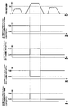
- 4 is a timing chart showing a traveling speed of a vehicle, a gain of a left / right active suspension, and a gain of a vertically moving active suspension. It is explanatory drawing which shows typically the rail vehicle to which the suspension control apparatus by 6th, 8th embodiment was applied.
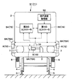
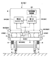
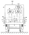
- a railway vehicle 1 (vehicle) has, for example, a vehicle body 2 on which passengers, passengers, etc. get on, and front and rear carts 3 (only one is shown) provided on the lower side of the vehicle body 2. ing. These trolleys 3 are spaced apart from each other on the front side and the rear side of the vehicle body 2, and each trolley 3 is provided with four wheels 4. The railway vehicle 1 travels along the rails 5 as each wheel 4 rotates on the left and right rails 5.
- a shaft spring 6 is provided between the carriage 3 and the wheel 4 to alleviate vibrations and shocks from the wheel 4 (wheel shaft).
- a plurality of air springs 7 serving as pillow springs are provided between the vehicle body 2 and the carriage 3, and a plurality of vertically moving active suspensions 8 serving as vertical power generating mechanisms are provided in parallel with the air springs 7.
- the air springs 7 and the vertically moving active suspensions 8 are arranged on the left and right sides of the carriage 3, and two are provided on the carriage 3. For this reason, a total of four air springs 7 and vertical movement active suspensions 8 are provided in the railway vehicle 1 as a whole.
- Each vertical movement active suspension 8 is constituted by an active damper that generates a force (vibration damping force) opposite to vibration by an actuator 8A.
- the active damper includes a piston that reciprocates within the cylinder.
- the active damper may be a hydraulic type or pneumatic type that uses hydraulic oil or compressed air as a power source, an electric type that uses an electric actuator, or an electromagnetic type that uses an electromagnetic force such as a linear motor.
- This vertical movement active suspension 8 generates a force that reduces the vibration against the vertical vibration of the vehicle body 2 relative to the carriage 3. Thereby, the vertical movement active suspension 8 reduces the vibration of the vehicle body 2 in the vertical direction.
- a left-right active suspension 9 is provided between the vehicle body 2 and the carriage 3 as a left-right power generation mechanism along the left-right direction of the vehicle 1.
- the left-right active suspension 9 is configured using an active damper that is actively operated, similar to the vertically-active active suspension 8. For this reason, the left-right active suspension 9 generates a force (vibration suppression force) opposite to the vibration by the actuator 9A.
- the left / right active suspension 9 generates a force that reduces vibration in response to vibration in the left-right direction of the vehicle body 2 with respect to the carriage 3. Thereby, the left-right active suspension 9 reduces left-right vibration of the vehicle body 2.
- the vehicle body vibration sensor 10 is provided on the vehicle body 2 on the upper side of the spring, for example, and detects vertical vibration, horizontal vibration, roll vibration, swere vibration, yaw vibration and the like of the vehicle body 2. That is, the vehicle body vibration sensor 10 constitutes a vehicle body state detection unit that detects the vibration state of the vehicle body 2.
- the vehicle body vibration sensor 10 includes, for example, a lateral acceleration sensor of the vehicle body 2 acting in the lateral direction with respect to the traveling direction of the vehicle 1, a longitudinal acceleration sensor of the vehicle body 2 acting in the longitudinal direction, a roll direction, a pitch direction, a yaw direction, etc.
- An angular velocity sensor for detecting vibration is used.
- the vehicle body vibration sensor 10 is a composite sensor that can measure vibrations in the vertical direction, vibration in the horizontal direction, roll vibration, pitch vibration, yaw vibration, swell vibration, bounce vibration, and the like together.
- the present invention is not limited to this, and these vibrations may be individually measured by separate sensors.
- the first controller 11 is configured by, for example, a microcomputer, and the force (damping control) that the vertical active suspension 8 should generate in order to control the vibration of the vehicle body 2 based on the detection signal from the vehicle vibration sensor 10. Force).
- the first controller 11 calculates a control command signal (control command) such as a target current value to be output to the actuator 8 A of the vertical movement active suspension 8 and controls the vibration damping force of the vertical movement active suspension 8. .
- the controller 11 controls the vibration damping force of the vertically moving active suspension 8 based on, for example, skyhook theory (skyhook control law) at every sampling time in order to reduce vertical vibration and roll vibration of the vehicle body 2.
- the vertical movement active suspension 8 is controlled so that the damping force is continuously or variably set in a plurality of stages in accordance with a control command signal supplied to the actuator 8A.
- the first controller 11 is connected to the second controller 12 via various networks such as CAN (Controller Area Network) and Ethernet (registered trademark). Thereby, the 1st controller 11 and the 2nd controller 12 are transmitting the state of each other by communication.
- CAN Controller Area Network
- Ethernet registered trademark
- the first controller 11 acquires, for example, the stroke amount X of the left-right active suspension 9 based on the signal from the second controller 12.
- the first controller 11 executes a cooperative control program, which will be described later, and adjusts the gain of the vertically moving active suspension 8 according to the stroke amount X of the horizontally moving active suspension 9 and the like.
- the second controller 12 is constituted by, for example, a microcomputer or the like, and in order to control the vibration of the vehicle body 2 on the basis of a detection signal from the vehicle body vibration sensor 10, a force (damping control) that the left-right active suspension 9 should generate Force).
- the second controller 12 calculates and processes a control command signal (control command) such as a target current value to be output to the actuator 9A of the left-right active suspension 9 and controls the vibration damping force of the left-right active suspension 9. .
- the controller 12 controls the vibration of the left-right active suspension 9 based on various control laws such as the Skyhook theory at every sampling time in order to reduce left-right vibration and roll vibration of the vehicle body 2. Control the power.
- the damping force is controlled variably continuously or in a plurality of stages according to a control command signal supplied to the actuator.
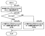
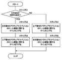
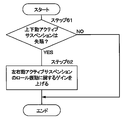
- the cooperative control program shown in FIG. 2 is repeatedly executed every predetermined control cycle.
- Step 1 shows an example of a stroke amount acquisition unit.
- the first controller 11 acquires the stroke amount X of the left-right active suspension 9 based on the signal from the second controller 12. Note that the first controller 11 may directly acquire the stroke amount X of the left-right active suspension 9 using a sensor or the like provided in the left-right active suspension 9.
- Step 2 shows an example of a stroke amount determination unit.
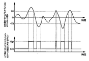
- Step 2 it is determined whether or not the stroke amount X of the left-right active suspension 9 exceeds a predetermined threshold value ⁇ Xd ( ⁇ Xd> X, X> Xd). Specifically, it is determined whether or not the left-right active suspension 9 has stroked beyond a predetermined length (Xd), for example, 80% of the stroke distance (
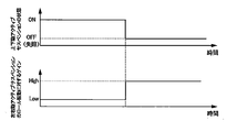
- Step 2 When it is determined as “YES” in Step 2, the left-right active suspension 9 is operating near the stroke limit on the expansion side or the contraction side, and there is a possibility that sufficient damping force against roll vibration cannot be generated. Therefore, the process proceeds to step 3 and the first controller 11 increases the gain related to the roll vibration of the vertically moving active suspension 8 (see FIG. 3). Thereby, the vibration damping force that is insufficient in the left and right active suspension 9 can be compensated for the roll vibration by the vibration suppressing forces of the two vertical active suspensions 8 provided on the left and right sides of the vehicle body 2.
- step 2 when it is determined as “NO” in step 2, it is considered that the left-right active suspension 9 is operating at a position away from the stroke limit, and a sufficient damping force can be generated against the roll vibration. Therefore, the process proceeds to step 4 and the first controller 11 reduces the gain related to the roll vibration of the vertically moving active suspension 8 (see FIG. 3). Thereby, roll vibration can be suppressed by the vibration damping force of the left and right active suspension 9 while the influence of the vibration damping force of the vertical movement active suspension 8 is reduced.
- the first controller 11 determines the generated force (vibration suppression force) of the vertically moving active suspension 8 according to the state of the horizontally moving active suspension 9.
- the first controller 11 cannot generate a sufficient damping force for the roll vibration from the stroke amount X of the left and right active suspension 9
- the first controller 11 increases the gain for the roll vibration of the vertically active suspension 8. .
- the left-right active suspension 9 cannot generate sufficient force to suppress roll vibration, roll vibration can be suppressed, so that riding comfort can be improved.
- FIG. 1 shows a second embodiment of the present invention.
- the feature of the second embodiment is that the cooperative control according to the first embodiment is applied to a vertically moving semi-active suspension.
- the same components as those in the first embodiment described above are denoted by the same reference numerals, and description thereof is omitted.
- the railway vehicle 21 according to the second embodiment is substantially the same as the railway vehicle 1 according to the first embodiment.
- the vehicle body 2, the carriage 3, the wheels 4, the vertical movement semi-active suspension 22, the left-right movement active suspension 9, the vehicle body A vibration sensor 10, first and second controllers 23, 12 and the like are provided.
- the vertically moving semi-active suspension 22 is configured using a semi-active damper capable of individually adjusting each damping force. That is, the vertically moving semi-active suspension 22 is configured by a semi-active damper that controls the flow of the working fluid by the actuator 22A.
- the semi-active damper may be, for example, a hydraulic type that uses hydraulic oil as a working fluid, or a pneumatic type that uses air as a working fluid.
- the vertical movement semi-active suspension 22 generates a damping force that reduces vibrations in the vertical direction of the vehicle body 2 with respect to the carriage 3 based on a control command from the first controller 23. Thereby, the vertically moving semi-active suspension 22 reduces the vibration of the vehicle body 2 in the vertical direction.
- the first controller 23 is configured in substantially the same manner as the first controller 11 according to the first embodiment.
- the vehicle 21 includes a vertically moving semi-active suspension 22 instead of the vertically moving active suspension 8. Therefore, the first controller 23 calculates the damping force that should be generated by the vertically moving semi-active suspension 22 in order to control the vibration of the vehicle body 2 based on the detection signal from the vehicle body vibration sensor 10.
- the first controller 23 calculates and processes a control command signal (control command) such as a target current value to be output to the actuator 22A of the vertical movement semi-active suspension 22 and controls the damping force of the vertical movement semi-active suspension 22.
- the vertical movement semi-active suspension 22 is controlled such that the damping force is variable between hardware and software continuously or in a plurality of stages according to a control command signal supplied to the actuator 22A.
- the first controller 23 is connected to the second controller 12 via various networks.
- the first controller 23 obtains, for example, the stroke amount X of the left-right active suspension 9 based on the signal from the second controller 12.
- the first controller 23 executes a cooperative control program substantially similar to the cooperative control program shown in FIG. 2 and adjusts the gain of the vertically moving semi-active suspension 22 according to the stroke amount X of the horizontally moving active suspension 9 and the like. .
- FIGS. 1, 4 and 5 show a third embodiment of the present invention.
- the feature of the third embodiment is that the gain for roll vibration of the vertically moving active suspension is switched in accordance with the piston speed of the horizontally moving semiactive suspension. Note that in the third embodiment, the same components as those in the first embodiment described above are denoted by the same reference numerals, and description thereof is omitted.
- the railway vehicle 31 according to the third embodiment is substantially the same as the railway vehicle 1 according to the first embodiment.
- the vehicle body 2, the carriage 3, the wheels 4, the vertical movement active suspension 8, the left-right movement semi-active suspension 32, the vehicle body A vibration sensor 10, first and second controllers 33, 34, and the like are provided.
- the left / right semi-active suspension 32 is configured using a semi-active damper capable of adjusting the damping force.
- the left and right moving semi-active suspension 32 controls the flow of the working fluid by the actuator 32A, for example, similarly to the vertically moving semi active suspension 22 according to the second embodiment.
- the left / right semi-active suspension 32 generates a damping force that reduces vibrations in response to vibrations in the left / right direction of the vehicle body 2 relative to the carriage 3 based on a control command from the second controller 12.
- the left-right motion semi-active suspension 32 reduces vibration in the left-right direction of the vehicle body 2.
- the first controller 33 is configured in substantially the same manner as the first controller 11 according to the first embodiment. Therefore, the first controller 33 calculates a damping force that should be generated by the vertical movement active suspension 8 in order to control the vibration of the vehicle body 2 based on the detection signal from the vehicle body vibration sensor 10. The first controller 33 calculates and processes a control command signal (control command) to be output to the actuator 8 ⁇ / b> A of the vertical movement active suspension 8 and controls the vibration damping force of the vertical movement active suspension 8.
- the first controller 33 is connected to the second controller 34 via various networks.
- the first controller 33 acquires, for example, the piston speed VP of the left / right semi-active suspension 32 based on the signal from the second controller 34.
- the first controller 33 executes a cooperative control program, which will be described later, and adjusts the vibration damping force of the vertically moving active suspension 8 according to the piston speed VP of the left and right moving semiactive suspension 32.
- the second controller 34 is configured in substantially the same manner as the second controller 12 according to the second embodiment.
- the left / right semi-active suspension 32 is configured by a semi-active damper.
- the second controller 34 calculates a damping force that should be generated by the left / right semi-active suspension 32 in order to control the vibration of the vehicle body 2 based on the detection signal from the vehicle body vibration sensor 10.
- the second controller 34 calculates and processes a control command signal (control command) such as a target current value to be output to the actuator 32A of the left / right semi-active suspension 32, and controls the damping force of the left / right semi-active suspension 32.
- the left / right semi-active suspension 32 is controlled so that the damping force is continuously variable between hardware and software, or variable in multiple stages, in accordance with a control command signal supplied to the actuator 32A.
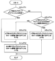
- FIG. 4 a cooperative control program for the vertical motion active suspension 8 and the lateral motion semi-active suspension 32 executed by the first controller 33 will be described with reference to FIG. 1, FIG. 4, and FIG. Note that the cooperative control program shown in FIG. 4 is repeatedly executed at predetermined control cycles.
- Step 11 shows an example of a piston speed acquisition unit.
- the first controller 33 acquires the piston speed VP of the left / right semi-active suspension 32 based on the signal from the second controller 34.
- the first controller 11 may directly acquire the piston speed VP of the left-right moving semi-active suspension 32 using a sensor or the like provided in the left-right moving semi-active suspension 32.
- step 12 shows an example of the piston speed determination unit.
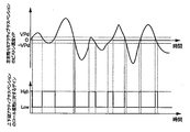
- step 12 it is determined whether or not the piston speed VP of the left / right semi-active suspension 32 is lower than a predetermined threshold value ⁇ VPd (
- the threshold value VPd is set to a value of the piston speed at which the left-right moving semi-active suspension 32 made of, for example, a semi-active damper cannot generate sufficient damping force to reduce roll vibration.
- the threshold value VPd is not limited to a constant value, and may be changed according to a required damping force.
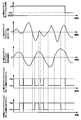
- Step 12 When it is determined as “YES” in Step 12, the piston speed VP of the left and right moving semi-active suspension 32 is lowered to a level where a desired damping force cannot be generated. Therefore, the process proceeds to step 13 and the first controller 33 increases the gain related to the roll vibration of the vertically moving active suspension 8 (see FIG. 5). As a result, the damping force that is insufficient in the laterally active semi-active suspension 32 can be compensated for the roll vibration by the damping force of the two vertically active active suspensions 8 provided on the left and right sides of the vehicle body 2.
- step 12 when it is determined as “NO” in step 12, the piston speed VP of the left-right semi-active suspension 32 is increased to a level at which a desired damping force can be generated. For this reason, the process proceeds to step 14, and the first controller 33 reduces the gain related to the roll vibration of the vertically moving active suspension 8 (see FIG. 5). Thereby, roll vibration can be suppressed by the damping force of the left and right moving semi-active suspension 32 in a state where the influence of the damping force of the vertically moving active suspension 8 is reduced.
- the third embodiment substantially the same operational effects as in the first embodiment can be obtained. Further, in the third embodiment, even when the expansion / contraction speed (piston speed VP) of the left / right semi-active suspension 32 composed of the semi-active damper is lowered and the generated damping force is insufficient, the vertical movement active suspension 8 It can be compensated by the damping force.
- FIG. 1 shows a fourth embodiment of the present invention.
- a feature of the fourth embodiment is that the cooperative control according to the third embodiment is applied to a vertically moving semi-active suspension. Note that in the fourth embodiment, the same components as those in the third embodiment described above are denoted by the same reference numerals, and description thereof is omitted.
- the railway vehicle 41 according to the fourth embodiment is substantially the same as the railway vehicle 1 according to the third embodiment.
- the vehicle body 2, the carriage 3, the wheels 4, the vertical movement semi-active suspension 42, the left-right movement semi-active suspension 32, A vehicle body vibration sensor 10, first and second controllers 43, 34, and the like are provided.
- the vertically moving semi-active suspension 42 is configured in substantially the same manner as the vertically moving semi-active suspension 22 according to the second embodiment. That is, the vertically moving semi-active suspension 42 is configured by a semi-active damper that controls the flow of the working fluid by the actuator 42A.
- the vertical movement semi-active suspension 42 generates a damping force that reduces the vibration with respect to the vertical vibration of the vehicle body 2 with respect to the carriage 3 based on a control command from the first controller 43. Thereby, the vertically moving semi-active suspension 42 reduces the vibration of the vehicle body 2 in the vertical direction.
- the first controller 43 is configured in substantially the same manner as the first controller 33 according to the third embodiment.
- the vertically moving semi-active suspension 42 is configured by a semi-active damper. Therefore, the first controller 43 calculates the damping force that should be generated by the vertically moving semi-active suspension 42 in order to control the vibration of the vehicle body 2 based on the detection signal from the vehicle body vibration sensor 10. Specifically, the first controller 43 calculates a control command signal to be output to the actuator 42A of the vertical movement semi-active suspension 42, and controls the damping force of the vertical movement semi-active suspension 42.
- the first controller 43 acquires, for example, the piston speed VP of the left / right semi-active suspension 32 based on the signal from the second controller 34.
- the first controller 43 executes a cooperative control program that is substantially the same as the cooperative control program shown in FIG. 4 and adjusts the gain of the vertically moving semi-active suspension 42 according to the piston speed VP of the horizontally moving semi-active suspension 32. To do.
- FIGS. 6 to 8 show a fifth embodiment of the present invention.
- the feature of the fifth embodiment resides in that the gains of the vertically moving active suspension and the horizontally moving active suspension are switched according to the traveling speed of the vehicle.
- the same components as those in the first embodiment described above are denoted by the same reference numerals, and the description thereof is omitted.
- the railway vehicle 51 according to the fifth embodiment is substantially the same as the railway vehicle 1 according to the first embodiment.
- a sensor 10, first and second controllers 53, 54 and the like are provided.
- the vehicle 51 includes a traveling speed acquisition unit 52 that acquires the traveling speed V.
- the traveling speed acquisition unit 52 may directly acquire the traveling speed V using a speed sensor or the like.
- the traveling speed acquisition unit 52 may indirectly acquire the traveling speed V based on a signal transmitted from another vehicle connected to the vehicle 51, an external command center, or the like.
- the first controller 53 is configured in substantially the same manner as the first controller 11 according to the first embodiment. Therefore, the first controller 53 calculates the damping force that should be generated by the vertical movement active suspension 8 in order to control the vibration of the vehicle body 2 based on the detection signal from the vehicle body vibration sensor 10. The first controller 53 performs arithmetic processing on a control command signal (control command) to be output to the actuator 8 ⁇ / b> A of the vertical movement active suspension 8 and controls the vibration damping force of the vertical movement active suspension 8.
- the first controller 53 executes a cooperative control program which will be described later, and adjusts the vibration damping force of the vertical movement active suspension 8 according to the traveling speed V of the vehicle 51.
- the first controller 53 is connected to the second controller 54 via various networks.
- the first controller 53 outputs a cooperative control signal for adjusting the gain of the left-right active suspension 9 toward the second controller 54 in accordance with the traveling speed V of the vehicle 51.
- the second controller 54 is configured in substantially the same manner as the second controller 12 according to the first embodiment. Therefore, the second controller 54 calculates the damping force that should be generated by the left-right active suspension 9 in order to control the vibration of the vehicle body 2 based on the detection signal from the vehicle body vibration sensor 10. The second controller 54 performs arithmetic processing on a control command signal (control command) to be output to the actuator 9 ⁇ / b> A of the left / right active suspension 9 and controls the vibration damping force of the left / right active suspension 9. Further, the second controller 54 adjusts the gain of the left-right active suspension 9 based on the cooperative control signal from the first controller 53.
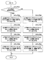
- Step 21 shows an example of the traveling speed determination unit.
- the traveling speed V of the vehicle 51 acquired by the traveling speed acquisition unit 52 is equal to or higher than a predetermined threshold value Vd (V ⁇ Vd).
- the threshold value Vd is a value that can be used to determine whether or not the vehicle is traveling at high speed when the speed of high-speed traveling (eg, 200 km / h or more) and the speed of low-speed traveling (eg, 160 km / h or less) are known. (For example, 180 km / h).
- the traveling speed V is equal to or higher than the threshold value Vd, and the vehicle 51 is traveling at a high speed.
- the first controller 53 outputs a cooperative control signal to the second controller 54.
- the second controller 54 increases the gain relating to the swere vibration and yaw vibration of the left-right active suspension 9.
- the second controller 54 reduces the gain relating to the roll vibration of the left-right active suspension 9.
- the first controller 53 increases the gain related to roll vibration of the vertically moving active suspension 8.
- the first controller 53 reduces the gain related to the bounce vibration and pitch vibration of the vertical movement active suspension 8 (see FIG. 8).
- the traveling speed V is lower than the threshold value Vd, and the vehicle 51 is traveling at a low speed.
- the first controller 53 increases the gain related to the bounce vibration and pitch vibration of the vertically moving active suspension 8.
- the first controller 53 reduces the gain related to the roll vibration of the vertical movement active suspension 8.
- the first controller 53 outputs a cooperative control signal to the second controller 54.
- the second controller 54 increases the gain related to the roll vibration of the left-right active suspension 9.
- the second controller 54 reduces the gain relating to the sway vibration and yaw vibration of the left-right active suspension 9 (see FIG. 8).
- the gains of the vertical motion active suspension 8 and the left and right motion active suspension 9 are switched according to the traveling speed V of the vehicle 51.
- the left-right active suspension 9 increases the gain of left-right vibration (Swe vibration and yaw vibration) and lowers the gain for roll vibration (see FIGS. 7 and 8). Instead, since the vertical movement active suspension 8 has a small amount of work, the gain against roll vibration is increased. As a result, the left and right active suspension 9 focuses on swe and yaw vibration, and the roll vibration can be reduced by the vertically active suspension 8.
- the amount of work of the vertically moving active suspension 8 is larger than that of the horizontally moving active suspension 9 when traveling at a low speed. Therefore, the vertical motion active suspension 8 increases the gain for vertical vibration (bounce vibration and pitch vibration) and decreases the gain for roll vibration. Instead, since the left-right active suspension 9 has a small amount of work, the gain for roll vibration is increased.
- FIG. 9 and FIG. 10 show a sixth embodiment of the present invention.
- a feature of the sixth embodiment resides in that the gains of the vertically moving active suspension and the horizontally moving active suspension are switched according to the traveling position of the vehicle.
- the same components as those in the fifth embodiment described above are denoted by the same reference numerals, and the description thereof is omitted.
- the railway vehicle 61 according to the sixth embodiment is substantially the same as the railway vehicle 1 according to the first embodiment.
- a sensor 10, first and second controllers 63, 64, and the like are provided.
- the vehicle 51 includes a position information acquisition unit 62 that acquires the current travel position P.
- the position information acquisition unit 62 may acquire a travel position based on, for example, kilometer information obtained from a monitor device, or may acquire a travel position based on position information obtained from GPS (Global Positioning System). .
- GPS Global Positioning System
- the first controller 63 is configured in substantially the same manner as the first controller 53 according to the fifth embodiment.
- the second controller 64 is configured in substantially the same manner as the second controller 54 according to the fifth embodiment.
- the first controller 63 executes a cooperative control program, which will be described later, and adjusts the vibration damping force of the vertically moving active suspension 8 according to the traveling position of the vehicle 61.
- the first controller 63 is connected to the second controller 64 via various networks.
- the first controller 63 outputs a cooperative control signal for adjusting the gain of the left-right active suspension 9 toward the second controller 64 according to the travel position of the vehicle 61.
- the second controller 64 adjusts the gain of the left / right active suspension 9 based on the cooperative control signal from the first controller 53.
- the cooperative control program shown in FIG. 10 is repeatedly executed every predetermined control cycle.
- Step 31 shows an example of the traveling position determination unit.
- the traveling position of the vehicle 61 acquired by the position information acquisition unit 62 is in a section where the left-right vibration is dominant.
- the section where the left-right vibration is dominant is, for example, a section prepared for high-speed travel.
- step 31 When it is determined as “YES” in step 31, the vehicle 61 is traveling in a section in which left-right vibration is dominant. At this time, the first controller 63 outputs a cooperative control signal to the second controller 64. Accordingly, in step 32, the second controller 64 increases the gain relating to the swere vibration and yaw vibration of the left-right active suspension 9. In the subsequent step 33, the second controller 64 reduces the gain related to the roll vibration of the left-right active suspension 9. In addition, in step 34, the first controller 63 increases the gain related to roll vibration of the vertically moving active suspension 8. In subsequent step 35, the first controller 63 reduces the gain related to the bounce vibration and pitch vibration of the vertically moving active suspension 8.
- step 36 the first controller 63 increases the gain relating to the bounce vibration and pitch vibration of the vertically moving active suspension 8.
- the first controller 63 reduces the gain related to the roll vibration of the vertical movement active suspension 8.
- the first controller 63 outputs a cooperative control signal to the second controller 64.
- step 38 the second controller 64 increases the gain relating to the roll vibration of the left-right active suspension 9.
- the second controller 64 reduces the gain relating to the swere vibration and yaw vibration of the left-right active suspension 9.
- the gains of the vertical motion active suspension 8 and the left and right motion active suspension 9 are adjusted according to the travel speed V, but the travel speed may be clearly defined for each section. As described above, in the section where the traveling speed is clearly defined, the gains of the vertical movement active suspension 8 and the left and right movement active suspension 9 may be adjusted according to the traveling position as in the sixth embodiment. .
- FIG. 6 and FIG. 11 show a seventh embodiment of the present invention.
- the feature of the seventh embodiment resides in that the gains of the vertically moving semiactive suspension and the horizontally moving semiactive suspension are switched according to the traveling speed of the vehicle. Note that, in the seventh embodiment, the same components as those in the fifth embodiment described above are denoted by the same reference numerals, and description thereof is omitted.
- the railway vehicle 71 according to the seventh embodiment is substantially the same as the railway vehicle 51 according to the fifth embodiment.
- the vehicle body 2, the carriage 3, the wheels 4, the vertical movement semi-active suspension 72, the lateral movement semi-active suspension 73, A vehicle body vibration sensor 10, first and second controllers 74, 75, and the like are provided.
- the vertically moving semi-active suspension 72 is configured in substantially the same manner as the vertically moving semi-active suspension 22 according to the second embodiment. That is, the vertically moving semi-active suspension 72 is configured by a semi-active damper that controls the flow of the working fluid by the actuator 72A.
- the vertical movement semi-active suspension 72 generates a damping force that reduces vibrations with respect to the vertical vibrations of the vehicle body 2 relative to the carriage 3 based on a control command from the first controller 74.
- the left / right semi-active suspension 73 is configured in substantially the same manner as the left / right semi-active suspension 32 according to the third embodiment. That is, the left-right moving semi-active suspension 73 is configured by a semi-active damper that controls the flow of the working fluid by the actuator 73A. The left-right movement semi-active suspension 73 generates a damping force that reduces vibrations in response to vibrations in the left-right direction of the vehicle body 2 with respect to the carriage 3 based on a control command from the second controller 75.
- the first controller 74 is configured in substantially the same manner as the first controller 53 according to the fifth embodiment. For this reason, the first controller 74 calculates the damping force that should be generated by the vertically moving semi-active suspension 72 in order to control the vibration of the vehicle body 2 based on the detection signal from the vehicle body vibration sensor 10. The first controller 74 calculates and processes a control command signal (control command) such as a target current value to be output to the actuator 72A of the vertical movement semi-active suspension 72, and controls the damping force of the vertical movement semi-active suspension 72. To do.
- a control command signal such as a target current value to be output to the actuator 72A of the vertical movement semi-active suspension 72
- the first controller 74 executes a cooperative control program described later, and adjusts the damping force of the vertically moving semi-active suspension 72 according to the traveling speed V of the vehicle 51.
- the first controller 74 is connected to the second controller 75 via various networks.
- the first controller 74 outputs a cooperative control signal for adjusting the gain of the left-right moving semi-active suspension 73 toward the second controller 75 according to the traveling speed V of the vehicle 71.
- the second controller 75 is configured in substantially the same manner as the second controller 54 according to the fifth embodiment. For this reason, the second controller 75 calculates a damping force that should be generated by the left / right semi-active suspension 73 in order to control the vibration of the vehicle body 2 based on the detection signal from the vehicle body vibration sensor 10. The second controller 75 computes a control command signal (control command) to be output to the actuator 73A of the left / right semi-active suspension 73 and controls the damping force of the left / right semi-active suspension 73. Further, the second controller 75 adjusts the gain of the left / right semi-active suspension 73 based on the cooperative control signal from the first controller 74.
- Step 41 shows an example of the traveling speed determination unit.
- the first controller 74 determines whether or not the traveling speed V of the vehicle 71 acquired by the traveling speed acquisition unit 52 is equal to or greater than a predetermined threshold value Vd (V ⁇ Vd).
- the traveling speed V is equal to or higher than the threshold value Vd, and the vehicle 71 is traveling at a high speed.
- the first controller 74 outputs a cooperative control signal to the second controller 75.
- the second controller 75 increases the gain related to the roll vibration of the left and right moving semi-active suspension 73.
- the first controller 74 decreases the gain related to roll vibration of the vertically moving semi-active suspension 72.
- step 41 when it is determined “NO” in step 41, the traveling speed V is lower than the threshold value Vd, and the vehicle 71 is traveling at a low speed. At this time, it is considered that the vertical motion semi-active suspension 72 can generate a larger damping force than the left-right motion semi-active suspension 73. For this reason, in step 44, the first controller 74 increases the gain related to the roll vibration of the vertically moving semi-active suspension 72. In addition, the first controller 74 outputs a cooperative control signal to the second controller 75. As a result, in step 45, the second controller 75 reduces the gain related to the roll vibration of the left and right moving semi-active suspension 73.
- the left and right moving semi-active suspension 73 increases the gain with respect to the left and right vibration and the roll vibration, and the vertical movement semi active suspension 72 decreases the gain with respect to the roll vibration in the seventh embodiment.
- the vertically moving semi-active suspension 72 increases the gain for vertical vibration and roll vibration, and the laterally moving semi-active suspension 73 decreases the gain for roll vibration.
- the gain for the roll vibration of the vertical movement semi-active suspension 72 and the left-right movement semi-active suspension 73 is adjusted according to the traveling speed V, and the semi-active suspensions 72 and 73 in the direction in which a force can be generated are rolled. Can play a role. As a result, optimal control can be performed and riding comfort can be improved. Therefore, in the seventh embodiment, substantially the same operational effects as in the fifth embodiment can be obtained.
- FIG. 9 and FIG. 12 show an eighth embodiment of the present invention.
- a feature of the eighth embodiment resides in that the gains of the vertically moving semiactive suspension and the horizontally moving semiactive suspension are switched according to the traveling position of the vehicle.
- the same components as those in the above-described sixth embodiment are denoted by the same reference numerals, and description thereof is omitted.
- the railway vehicle 81 according to the eighth embodiment is substantially the same as the railway vehicle 61 according to the sixth embodiment.
- the vehicle body 2, the carriage 3, the wheels 4, the vertical movement semi-active suspension 82, the lateral movement semi-active suspension 83, A vehicle body vibration sensor 10, first and second controllers 84, 85, and the like are provided.
- the vertically moving semi-active suspension 82 is configured in substantially the same manner as the vertically moving semi-active suspension 22 according to the second embodiment. That is, the vertically moving semi-active suspension 82 is configured by a semi-active damper that controls the flow of the working fluid by the actuator 82A. The vertical movement semi-active suspension 82 generates a damping force that reduces the vibration with respect to the vertical vibration of the vehicle body 2 relative to the carriage 3 based on a control command from the first controller 84.
- the left / right semi-active suspension 83 is configured in substantially the same manner as the left / right semi-active suspension 32 according to the third embodiment. That is, the left-right moving semi-active suspension 83 is configured by a semi-active damper that controls the flow of the working fluid by the actuator 83A. The left / right semi-active suspension 83 generates a damping force that reduces the vibration with respect to the left / right vibration of the vehicle body 2 relative to the carriage 3 based on a control command from the second controller 85.
- the first controller 84 is configured in substantially the same manner as the first controller 63 according to the sixth embodiment. Therefore, the first controller 84 calculates the damping force that should be generated by the vertically moving semi-active suspension 82 in order to control the vibration of the vehicle body 2 based on the detection signal from the vehicle body vibration sensor 10. The first controller 84 calculates and processes a control command signal (control command) to be output to the actuator 82A of the vertically moving semi-active suspension 82, and controls the damping force of the vertically moving semi-active suspension 82.
- control command control command
- the first controller 84 executes a cooperative control program to be described later, and adjusts the damping force of the vertically moving semi-active suspension 82 according to the traveling position of the vehicle 51.
- the first controller 84 is connected to the second controller 85 via various networks.
- the first controller 84 outputs a cooperative control signal for adjusting the gain of the left / right semi-active suspension 83 toward the second controller 85 according to the travel position of the vehicle 81.
- the second controller 85 is configured in substantially the same manner as the second controller 64 according to the sixth embodiment. For this reason, the second controller 85 calculates a damping force that should be generated by the left / right semi-active suspension 73 in order to control the vibration of the vehicle body 2 based on the detection signal from the vehicle body vibration sensor 10. The second controller 85 computes a control command signal (control command) to be output to the actuator 83A of the left / right semi-active suspension 83, and controls the damping force of the left / right semi-active suspension 83. Further, the second controller 85 adjusts the gain of the left / right semi-active suspension 83 based on the cooperative control signal from the first controller 84.
- the cooperative control program shown in FIG. 12 is repeatedly executed every predetermined control cycle.
- Step 51 shows an example of the traveling position determination unit.
- the first controller 84 determines whether or not the travel position of the vehicle 81 acquired by the position information acquisition unit 62 is in a section where left-right vibration is dominant.
- step 51 When it is determined “YES” in step 51, the vehicle 81 is traveling in a section in which left-right vibration is dominant. At this time, it is considered that the laterally moving semi-active suspension 83 can generate a larger damping force than the vertically moving semi-active suspension 72. For this reason, the first controller 84 outputs a cooperative control signal to the second controller 85. As a result, in step 52, the second controller 85 increases the gain relating to the roll vibration of the left-right moving semi-active suspension 83. In addition, in step 53, the first controller 84 reduces the gain related to roll vibration of the vertically moving semi-active suspension 82.
- step 54 the first controller 84 increases the gain related to the roll vibration of the vertically moving semi-active suspension 82.
- the first controller 84 outputs a cooperative control signal to the second controller 85.
- the second controller 85 reduces the gain related to the roll vibration of the left-right moving semi-active suspension 83.
- FIG. 1, FIG. 13 and FIG. 14 show a ninth embodiment of the present invention.
- the feature of the ninth embodiment is that the gain of the left-right active suspension is switched when the vertical active suspension is lost. Note that in the ninth embodiment, identical symbols are assigned to components identical to those in the first embodiment described above, and descriptions thereof are omitted.
- the railway vehicle 91 according to the ninth embodiment is substantially the same as the railway vehicle 1 according to the first embodiment.
- the sensor 10 includes first and second controllers 92 and 93.
- the first controller 92 is configured in substantially the same manner as the first controller 11 according to the first embodiment. Therefore, the first controller 92 calculates the damping force that should be generated by the vertical movement active suspension 8 in order to control the vibration of the vehicle body 2 based on the detection signal from the vehicle body vibration sensor 10. The first controller 92 calculates a control command signal (control command) to be output to the actuator 8 ⁇ / b> A of the vertical movement active suspension 8 and controls the vibration damping force of the vertical movement active suspension 8.
- the first controller 92 grasps whether or not the vertically moving active suspension 8 has failed (OFF state) based on the value of the current flowing through the actuator 8A, for example.
- the first controller 92 is connected to the second controller 93 via various networks.
- the first controller 92 executes the cooperative control program shown in FIG. 13, and the gain of the left and right active suspension 9 is directed toward the second controller 93 depending on whether or not the vertically active suspension 8 has failed.
- a cooperative control signal for adjusting the output is output.
- the second controller 93 is configured in substantially the same manner as the second controller 12 according to the first embodiment. Therefore, the second controller 93 calculates the damping force that should be generated by the left-right active suspension 9 in order to control the vibration of the vehicle body 2 based on the detection signal from the vehicle body vibration sensor 10. The second controller 93 calculates a control command signal (control command) to be output to the actuator 9 ⁇ / b> A of the left / right active suspension 9 and controls the damping force of the left / right active suspension 9. Further, the second controller 93 adjusts the gain of the left-right active suspension 9 based on the cooperative control signal from the first controller 92.
- the cooperative control program shown in FIG. 13 is repeatedly executed every predetermined control cycle.
- Step 61 shows an example of a failure state determination unit.
- the first controller 92 determines whether or not the vertically moving active suspension 8 has failed.
- step 61 When it is determined as “YES” in step 61, it is considered that the vertical movement active suspension 8 has a problem and the vertical movement active suspension 8 is in a state where the desired vibration damping force cannot be generated (OFF state).
- the first controller 92 outputs a cooperative control signal to the second controller 93.
- the 2nd controller 93 raises the gain regarding the roll vibration of the left-right active suspension 9 (refer FIG. 14).
- step 61 when it is determined as “NO” in step 61, it is considered that the vertical movement active suspension 8 is in a state (ON state) in which a desired damping force can be generated. For this reason, in order to control the vertical movement active suspension 8 and the left and right movement active suspension 9 as usual, the gain is maintained as it is, and the cooperative control process is ended. At this time, the vertical movement active suspension 8 and the left and right movement active suspension 9 respectively generate vibration damping forces that suppress the vibration of the vehicle body 2.
- the left and right active suspension 9 performs control so as to suppress not only the left and right vibrations and yaw vibrations of the vehicle body 2 but also the roll vibrations. Change the control law to Thereby, even if the vertical movement active suspension 8 becomes uncontrollable, roll vibration can be suppressed. For this reason, even when a problem occurs in the vertical movement active suspension 8, it is possible to suppress the deterioration of riding comfort.
- the control gain for roll vibration is increased or decreased when the vertically moving active suspension 8 fails.
- the present invention is not limited to this.
- the control gain for the roll vibration of the left and right movement active suspension 9 is 0.
- a method of changing to a gain capable of controlling vibration may be used.
- the vertical movement active suspension 8 and the left and right movement active suspension 9 are both constituted by active dampers.
- the present invention is not limited to this, and may be applied to a railway vehicle including a vertically moving semi-active suspension made of a semi-active damper and a left-right moving active suspension made of an active damper.
- the present invention may be applied to a railway vehicle equipped with a vertically moving active suspension composed of active dampers and a left and right moving semiactive suspension composed of semiactive dampers.
- the left / right semi-active suspension can only generate a force in the direction opposite to the piston expansion / contraction direction.
- the direction of the force that suppresses the roll vibration does not necessarily coincide with the direction of the force that is generated by the left-right moving semi-active suspension. Therefore, the effect is limited compared to the ninth embodiment.
- roll vibration can be reduced as compared with a configuration in which the vertically moving active suspension and the horizontally moving semiactive suspension are not linked.
- FIG. 1, FIG. 15 and FIG. 16 show a tenth embodiment of the present invention.
- the feature of the tenth embodiment is that, in addition to whether the vertically moving semi-active suspension has failed, the direction of the damping force generated by the vertically moving semi-active suspension is considered, The configuration is such that the gain of the dynamic active suspension is switched. Note that in the tenth embodiment, identical symbols are assigned to components identical to those in the first embodiment described above, and descriptions thereof are omitted.
- the railway vehicle 101 according to the tenth embodiment is substantially the same as the railway vehicle 1 according to the first embodiment.
- the vehicle body 2, the carriage 3, the wheels 4, the vertically moving semi-active suspension 102, the laterally moving active suspension 9, the vehicle body A vibration sensor 10 and first and second controllers 103 and 104 are provided.
- the vertical movement semi-active suspension 102 is configured in the same manner as the vertical movement semi-active suspension 22 according to the second embodiment. That is, the vertically moving semi-active suspension 102 controls the flow of the working fluid by the actuator 102A.
- the vertically moving semi-active suspension 102 generates a damping force that reduces vibrations with respect to the vertical vibrations of the vehicle body 2 relative to the carriage 3 based on a control command from the first controller 103.
- the first controller 103 is configured in substantially the same manner as the first controller 92 according to the ninth embodiment. Therefore, the first controller 103 calculates the damping force that should be generated by the vertically moving semi-active suspension 102 in order to control the vibration of the vehicle body 2 based on the detection signal from the vehicle body vibration sensor 10. The first controller 103 computes a control command signal (control command) to be output to the actuator 102A of the vertical movement semi-active suspension 102, and controls the damping force of the vertical movement semi-active suspension 102.
- control command control command
- the first controller 103 grasps whether or not the vertically moving semi-active suspension 102 has failed based on the value of the current flowing through the actuator 102A, for example.
- the first controller 103 is connected to the second controller 104 via various networks.
- the first controller 103 executes the cooperative control program shown in FIG. 15, depending on whether or not the vertically moving semiactive suspension 102 has failed, the direction of the damping force of the vertically moving semiactive suspension 102, and the like. Then, a cooperative control signal for adjusting the gain of the left-right active suspension 9 is output toward the second controller 104.
- the second controller 104 is configured in substantially the same manner as the second controller 12 according to the first embodiment. Therefore, the second controller 104 calculates the damping force that should be generated by the left-right active suspension 9 in order to control the vibration of the vehicle body 2 based on the detection signal from the vehicle body vibration sensor 10. The second controller 104 calculates a control command signal (control command) to be output to the actuator 9 ⁇ / b> A of the left / right active suspension 9 and controls the damping force of the left / right active suspension 9. Further, the second controller 104 adjusts the gain of the left-right active suspension 9 based on the cooperative control signal from the first controller 103.
- FIG. 15 a cooperative control program for the vertically moving semi-active suspension 102 and the laterally moving active suspension 9 executed by the first and second controllers 103 and 104 will be described with reference to FIGS. 1, 15, and 16.
- FIG. 15 Note that the cooperative control program shown in FIG. 15 is repeatedly executed at predetermined control cycles.
- Step 71 shows an example of a failure state determination unit.
- the first controller 103 determines whether or not the vertically moving semi-active suspension 102 has failed. If “YES” is determined in step 71, the first controller 103 outputs a cooperative control signal to the second controller 104. Thereby, in step 72, the 2nd controller 104 raises the gain regarding the roll vibration of the left-right active suspension 9 (refer FIG. 16).
- Step 73 shows an example of the damping force direction determination unit.
- the first controller 103 determines whether or not the direction of the force for suppressing the roll vibration matches the direction of the force generated by the vertically moving semi-active suspension 102.
- the vertically moving semi-active suspension 102 can generate only a force in the direction opposite to the piston expansion / contraction direction. Therefore, in step 73, it is determined whether or not the direction of the force for suppressing the roll vibration and the piston expansion / contraction direction of the vertically moving semi-active suspension 102 are opposite to each other.
- step 73 When it is determined “YES” in step 73, the direction of the force for suppressing the roll vibration and the direction of the force generated by the vertically moving semi-active suspension 102 are the same. At this time, the vertically moving semi-active suspension 102 formed of a semi-active damper can suppress roll vibration. Therefore, the process moves to step 74, and the first controller 103 increases the gain related to the roll vibration of the vertically moving semi-active suspension 102 (see FIG. 16).
- step 73 when “NO” is determined in step 73, the direction of the force for suppressing the roll vibration and the direction of the force generated by the vertical movement semi-active suspension 102 do not coincide with each other, and the vertical movement semi consisting of the semi-active dampers.
- the active suspension 102 cannot suppress roll vibration. Therefore, the process proceeds to step 75, and the first controller 103 reduces the gain related to the roll vibration of the vertically moving semi-active suspension 102.
- the first controller 103 outputs a cooperative control signal to the second controller 104. Thereby, the process proceeds to step 72, and the second controller 104 increases the gain relating to the roll vibration of the left-right active suspension 9 (see FIG. 16).
- the left and right moving active suspension 9 performs control to suppress roll vibration. For this reason, in the tenth embodiment, substantially the same operational effects as those in the ninth embodiment can be obtained.
- the vertical movement semi-active suspension 102 is configured by a semi-active damper, even when the vertical movement semi-active suspension 102 is controllable, there is a state where roll vibration cannot be suppressed. is there.
- the direction of the force generated to suppress the roll vibration may be different from the direction of the force generated by the vertical movement semi-active suspension 102.
- the vertically moving semi-active suspension 102 can only perform control such that the damping force becomes small with respect to roll vibration, and cannot suppress roll vibration.
- the vertical movement semi-active suspension 102 stops the roll control and instead moves to the left and right.
- the active suspension 9 performs roll control. Thereby, even when the vertically moving semi-active suspension 102 is configured by a semi-active damper, roll vibration can be suppressed in cooperation with the left-right moving active suspension 9.
- the expansion / contraction direction of the vertical movement semi-active suspension 102 that is, the positive / negative of the piston speed, is changed. It must be an understandable system. Such information may be estimated from vehicle body acceleration, or may be measured by attaching a stroke sensor to the vertically moving semi-active suspension 102.
- the left and right movement active suspension 9 vibrates. It was set as the structure which suppresses.
- the present invention is not limited to this, and when the left-right active suspension or the left-right active semi-suspension cannot generate sufficient force to suppress vibration, the vertical active suspension may be used to suppress vibration.
- the operation of the vertical movement active suspension 8 and the movement of the horizontal movement active suspension 9 are both known, but the present invention is not limited to this.
- the state of the left-right active suspension 9 is estimated, and the up-down active suspension 8 is estimated. It is good also as a structure which controls. Specifically, by estimating the state of the left and right active suspension 9, in a situation where the left and right active suspension 9 hardly generates force, it is possible to perform coordinated control such that the vertical active suspension 8 supplements roll control. It is. For this purpose, it is necessary to estimate the stroke state of the left-right active suspension 9.
- state estimation using the Kalman filter 112 can be considered.
- the Kalman filter 112 estimates the stroke state of the left-right active suspension 9 based on, for example, a signal from the vehicle body vibration sensor 10 and the state of the vertical-motion active suspension 8. If the stroke of the left / right active suspension 9 can be estimated, the first controller 11 can control the up / down active suspension 8 in cooperation with the left / right active suspension 9. This configuration can also be applied to the second to fourth embodiments.
- the first and second controllers 11 and 12 separately control the vertical movement active suspension 8 and the left and right movement active suspension 9, but the present invention is not limited to this.
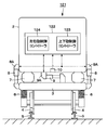
- both the vertical movement active suspension 8 and the left and right movement active suspension 9 are controlled by a single controller 122 in which the first and second controllers are integrated. It is good also as a structure.
- the controller 122 includes a vertical movement control controller 123 for controlling the generated force of the vertical movement active suspension 8 and a left / right movement control controller 124 for controlling the generated force of the left / right movement active suspension 9. .
- This configuration can also be applied to the second to ninth embodiments.
- the first and second controllers 11 and 12 are configured to control the vertical movement active suspension 8 and the left and right movement active suspension 9 according to the Skyhook control law.
- the present invention is not limited to this, and the vertical movement active suspension and the left and right movement active suspension may be controlled based on other control laws such as an LQG control law and an H ⁇ control law. This configuration can also be applied to the second to tenth embodiments.
- the roll vibration of the vehicle body 2 is cooperatively controlled by the vertical motion active suspension 8 and the lateral motion active suspension 9.
- the present invention is not limited to this, and other vibrations may be cooperatively controlled by the vertical movement active suspension 8 and the left-right movement active suspension 9. This configuration can also be applied to the second to tenth embodiments.
- the vertical motion control controller determines the generated force of the vertical power generation mechanism according to the state of the left and right power generation mechanism. For this reason, when the vibration of the vehicle body cannot be suppressed by the left and right power generation mechanism, the vibration of the vehicle body can be suppressed by the generated force of the vertical power generation mechanism, and the riding comfort of the vehicle can be improved.
- the vertical power generation mechanism and the left / right power generation mechanism are composed of a vertical motion control damper and a left / right motion control damper that control the flow of the working fluid by an actuator. For this reason, the vertical motion control controller can determine the generated force of the vertical motion control damper according to the state of the lateral motion control damper.
- the left / right motion control controller controls to increase the generating force of the left / right power generating mechanism when the generating force of the vertical vibration by the vertical power generating mechanism is insufficient. For this reason, when the generation force of the vertical vibration by the vertical power generation mechanism is insufficient and the vibration of the vehicle body cannot be suppressed, the generation force of the left and right power generation mechanism can be increased to suppress the vibration of the vehicle body.
- the vertical motion controller controls to increase the generated force of the vertical power generation mechanism when the horizontal vibration generation force by the left and right power generation mechanism is insufficient. For this reason, when the generation force of the left-right vibration by the left-right power generation mechanism is insufficient and the vibration of the vehicle body cannot be suppressed, the generation force of the vertical power generation mechanism can be increased to suppress the vibration of the vehicle body.
- the left / right motion controller increases the power generated by the left / right power generation mechanism when the vehicle travel speed is high, and the up / down motion controller controls the vertical power generation mechanism during low speed travel at a lower speed than during high speed travel. Increase the power of generation.
- vibration in the left-right direction is dominant due to the influence of aerodynamic vibration or the like.
- the left-right motion controller increases the generated force of the left-right power generation mechanism, the left-right vibration generated during high-speed traveling can be suppressed by the generated force of the left-right power generation mechanism.
- the vertical vibration becomes dominant.
- the vertical motion control controller increases the generated force of the vertical power generation mechanism, the vertical vibration generated during low-speed traveling can be suppressed by the generated force of the vertical power generation mechanism.
- vibration suppression can be supplemented, and both can be coordinated and controlled.
- a suspension control device provided in a vehicle having a vehicle body and a carriage is a vertical power generation mechanism provided between the vehicle body and the carriage, and is a vibration in the vertical direction.
- a vertical power generation mechanism for generating a force against the vehicle, and a left-right power generation mechanism to be provided between the vehicle body and the carriage, wherein the left-right power generation mechanism generates a force against vibration in the left-right direction A vertical motion control controller that controls the force generated by the vertical power generation mechanism; and a left / right motion control controller that controls the force generated by the left / right power generation mechanism, wherein the vertical motion control controller
- the force generated by the vertical power generation mechanism is determined according to the state of the generation mechanism.
- the vertical power generation mechanism and the left-right power generation mechanism are a vertical movement control damper and a horizontal movement control damper that control the flow of the working fluid by an actuator.
- the left-right motion control controller generates the left-right power generation mechanism when the force generated by the vertical power generation mechanism with respect to the vertical vibration is insufficient.
- the left and right power generation mechanism is controlled to increase the force.
- the vertical motion control controller generates the vertical power generation mechanism when the force generated by the left / right power generation mechanism with respect to the vibration in the horizontal direction is insufficient.
- the vertical power generation mechanism is controlled so as to increase the force.
- the left-right motion control controller increases the force generated by the left-right power generation mechanism when the traveling speed of the vehicle is higher than a predetermined speed.
- the controller increases the force generated by the vertical power generation mechanism when the traveling speed of the vehicle is lower than the predetermined speed.
- the force generated by the vertical power generation mechanism and the force generated by the left and right power generation mechanism are obtained by changing a gain. Adjusted.
Landscapes
- Engineering & Computer Science (AREA)
- Mechanical Engineering (AREA)
- Vehicle Body Suspensions (AREA)
Abstract
Description
Claims (7)
- 車体と台車とを有する車両に設けられるサスペンション制御装置であって、
前記車体と前記台車との間に設けられるための上下動力発生機構であって、上下方向の振動に対して力を発生させる上下動力発生機構と、
前記車体と前記台車との間に設けられるための左右動力発生機構であって、左右方向の振動に対して力を発生させる左右動力発生機構と、
前記上下動力発生機構が発生させる力を制御する上下動制御コントローラと、
前記左右動力発生機構が発生させる力を制御する左右動制御コントローラと、
を備え、
前記上下動制御コントローラは、前記左右動力発生機構の状態に応じて、前記上下動力発生機構が発生させる力を決定する
サスペンション制御装置。 - 請求項1に記載のサスペンション制御装置であって、
前記上下動力発生機構および前記左右動力発生機構は、アクチュエータにより作動流体の流れを制御する上下動制御ダンパおよび左右動制御ダンパである
サスペンション制御装置。 - 請求項1に記載のサスペンション制御装置であって、
前記左右動制御コントローラは、前記上下方向の振動に対して前記上下動力発生機構が発生させる力が不足するときは前記左右動力発生機構が発生させる力を高めるように、前記左右動力発生機構を制御する
サスペンション制御装置。 - 請求項1に記載のサスペンション制御装置であって、
前記上下動制御コントローラは、前記左右方向の振動に対して前記左右動力発生機構が発生させる力が不足するときは前記上下動力発生機構が発生させる力を高めるように、前記上下動力発生機構を制御する
サスペンション制御装置。 - 請求項1に記載のサスペンション制御装置であって、
前記左右動制御コントローラは、前記車両の走行速度が所定速度以上に高速のときは、前記左右動力発生機構が発生させる力を高め、
前記上下動制御コントローラは、前記車両の走行速度が前記所定速度よりも低速のときは、前記上下動力発生機構が発生させる力を高める
サスペンション制御装置。 - 請求項1に記載のサスペンション制御装置であって、
前記上下動力発生機構が発生させる力、および、前記左右動力発生機構が発生させる力は、ゲインを変化させることにより調整される
サスペンション制御装置。 - 車両であって、
前記車体と、
前記台車と、
請求項1に記載のサスペンション制御装置と を備えた車両。
Priority Applications (3)
| Application Number | Priority Date | Filing Date | Title |
|---|---|---|---|
| GB1813310.8A GB2562676B (en) | 2016-02-24 | 2017-02-10 | Suspension control device |
| CN201780012765.9A CN108698617B (zh) | 2016-02-24 | 2017-02-10 | 悬架控制装置 |
| JP2018501570A JP6571264B2 (ja) | 2016-02-24 | 2017-02-10 | サスペンション制御装置 |
Applications Claiming Priority (2)
| Application Number | Priority Date | Filing Date | Title |
|---|---|---|---|
| JP2016033330 | 2016-02-24 | ||
| JP2016-033330 | 2016-02-24 |
Publications (1)
| Publication Number | Publication Date |
|---|---|
| WO2017145794A1 true WO2017145794A1 (ja) | 2017-08-31 |
Family
ID=59686356
Family Applications (1)
| Application Number | Title | Priority Date | Filing Date |
|---|---|---|---|
| PCT/JP2017/004857 Ceased WO2017145794A1 (ja) | 2016-02-24 | 2017-02-10 | サスペンション制御装置 |
Country Status (4)
| Country | Link |
|---|---|
| JP (1) | JP6571264B2 (ja) |
| CN (1) | CN108698617B (ja) |
| GB (1) | GB2562676B (ja) |
| WO (1) | WO2017145794A1 (ja) |
Families Citing this family (4)
| Publication number | Priority date | Publication date | Assignee | Title |
|---|---|---|---|---|
| JP6876137B2 (ja) * | 2017-09-27 | 2021-05-26 | 日立Astemo株式会社 | 鉄道車両用振動制御装置 |
| JP6951372B2 (ja) * | 2019-01-23 | 2021-10-20 | Kyb株式会社 | 鉄道車両用制振装置 |
| CN111469622B (zh) * | 2019-01-24 | 2023-09-29 | 湖南工业大学 | 一种高速列车横向半主动悬架容错控制系统及方法 |
| EP4339056A1 (de) * | 2022-09-16 | 2024-03-20 | HEMSCHEIDT Engineering GmbH & Co. KG | Schienenfahrzeug mit einem fahrwerk und einer wankkompensationseinrichtung sowie wankkompensationseinrichtung insbesondere für ein schienenfahrzeug |
Citations (3)
| Publication number | Priority date | Publication date | Assignee | Title |
|---|---|---|---|---|
| JPH10147241A (ja) * | 1996-11-20 | 1998-06-02 | Hitachi Ltd | 鉄道車両の車体曲げ振動低減装置 |
| JP2000264205A (ja) * | 1999-03-19 | 2000-09-26 | Tokico Ltd | 車両用制振装置 |
| EP2842826A1 (en) * | 2013-08-28 | 2015-03-04 | Bombardier Transportation GmbH | Vehicle having side wind effect compensation |
Family Cites Families (5)
| Publication number | Priority date | Publication date | Assignee | Title |
|---|---|---|---|---|
| JPH0516543U (ja) * | 1991-08-21 | 1993-03-02 | 近畿車輌株式会社 | 鉄道車両の緩衝特性制御装置 |
| JPH0516544U (ja) * | 1991-08-21 | 1993-03-02 | 近畿車輌株式会社 | 鉄道車両の緩衝制御装置 |
| JP2000103334A (ja) * | 1998-09-29 | 2000-04-11 | Tokico Ltd | 車両横ゆれ制振装置 |
| JP4070677B2 (ja) * | 2003-07-25 | 2008-04-02 | 東急車輛製造株式会社 | 鉄道車両 |
| CN102963390B (zh) * | 2012-05-31 | 2015-03-04 | 南京浦镇海泰制动设备有限公司 | 铁路客车用制动控制装置 |
-
2017
- 2017-02-10 GB GB1813310.8A patent/GB2562676B/en active Active
- 2017-02-10 WO PCT/JP2017/004857 patent/WO2017145794A1/ja not_active Ceased
- 2017-02-10 JP JP2018501570A patent/JP6571264B2/ja active Active
- 2017-02-10 CN CN201780012765.9A patent/CN108698617B/zh active Active
Patent Citations (3)
| Publication number | Priority date | Publication date | Assignee | Title |
|---|---|---|---|---|
| JPH10147241A (ja) * | 1996-11-20 | 1998-06-02 | Hitachi Ltd | 鉄道車両の車体曲げ振動低減装置 |
| JP2000264205A (ja) * | 1999-03-19 | 2000-09-26 | Tokico Ltd | 車両用制振装置 |
| EP2842826A1 (en) * | 2013-08-28 | 2015-03-04 | Bombardier Transportation GmbH | Vehicle having side wind effect compensation |
Also Published As
| Publication number | Publication date |
|---|---|
| CN108698617A (zh) | 2018-10-23 |
| GB2562676A (en) | 2018-11-21 |
| GB2562676B (en) | 2021-03-10 |
| CN108698617B (zh) | 2020-08-18 |
| GB201813310D0 (en) | 2018-09-26 |
| JPWO2017145794A1 (ja) | 2018-12-13 |
| JP6571264B2 (ja) | 2019-09-04 |
Similar Documents
| Publication | Publication Date | Title |
|---|---|---|
| JP4972440B2 (ja) | 減衰力可変ダンパの制御装置 | |
| JP6571264B2 (ja) | サスペンション制御装置 | |
| JP5704306B2 (ja) | 鉄道車両用振動制御装置 | |
| US9162688B2 (en) | Vibrational component acceleration estimation device and vibrational component acceleration estimation method for railway vehicle | |
| JP2008247333A (ja) | 鉄道車両用振動制御装置 | |
| CN115135556A (zh) | 工作状态诊断装置 | |
| WO2018155329A1 (ja) | アクチュエータ装置 | |
| JP2008247357A (ja) | サスペンション制御装置 | |
| JP5522549B2 (ja) | 鉄道車両用振動制御装置 | |
| JP6474112B2 (ja) | 車両制振装置 | |
| JP2003320931A (ja) | 鉄道車両振動抑制装置 | |
| JP2012184000A5 (ja) | ||
| JP6864490B2 (ja) | 鉄道車両の振動制御装置 | |
| JP6671106B2 (ja) | 鉄道車両用ヨーダンパ装置 | |
| JP2013241075A (ja) | サスペンション制御装置 | |
| JP2012179970A (ja) | サスペンション制御装置 | |
| JP6399590B2 (ja) | 減衰力調整式緩衝器及びそれを用いた車両システム | |
| JP4435303B2 (ja) | 減衰力可変ダンパの制御装置 | |
| JP6318450B2 (ja) | 減衰力調整式緩衝器の制御装置 | |
| JP2014198519A (ja) | サスペンション制御装置 | |
| JP2013112313A (ja) | 減衰力調整式シリンダ装置 | |
| JP5180144B2 (ja) | 鉄道車両の制振装置 | |
| JP2009137342A (ja) | 減衰力可変ダンパの制御装置 | |
| JP5090977B2 (ja) | 減衰力可変ダンパの制御装置 | |
| JP2012076565A (ja) | 鉄道車両用振動制御装置 |
Legal Events
| Date | Code | Title | Description |
|---|---|---|---|
| ENP | Entry into the national phase |
Ref document number: 2018501570 Country of ref document: JP Kind code of ref document: A |
|
| ENP | Entry into the national phase |
Ref document number: 201813310 Country of ref document: GB Kind code of ref document: A Free format text: PCT FILING DATE = 20170210 |
|
| WWE | Wipo information: entry into national phase |
Ref document number: 1813310.8 Country of ref document: GB |
|
| NENP | Non-entry into the national phase |
Ref country code: DE |
|
| 121 | Ep: the epo has been informed by wipo that ep was designated in this application |
Ref document number: 17756235 Country of ref document: EP Kind code of ref document: A1 |
|
| 122 | Ep: pct application non-entry in european phase |
Ref document number: 17756235 Country of ref document: EP Kind code of ref document: A1 |