WO2017145507A1 - 二次電池用非水電解質、非水電解質二次電池、及び非水電解質二次電池の製造方法 - Google Patents
二次電池用非水電解質、非水電解質二次電池、及び非水電解質二次電池の製造方法 Download PDFInfo
- Publication number
- WO2017145507A1 WO2017145507A1 PCT/JP2016/087941 JP2016087941W WO2017145507A1 WO 2017145507 A1 WO2017145507 A1 WO 2017145507A1 JP 2016087941 W JP2016087941 W JP 2016087941W WO 2017145507 A1 WO2017145507 A1 WO 2017145507A1
- Authority
- WO
- WIPO (PCT)
- Prior art keywords
- secondary battery
- aqueous electrolyte
- positive electrode
- nonaqueous electrolyte
- negative electrode
- Prior art date
- Legal status (The legal status is an assumption and is not a legal conclusion. Google has not performed a legal analysis and makes no representation as to the accuracy of the status listed.)
- Ceased
Links
Images


Classifications
-
- H—ELECTRICITY
- H01—ELECTRIC ELEMENTS
- H01M—PROCESSES OR MEANS, e.g. BATTERIES, FOR THE DIRECT CONVERSION OF CHEMICAL ENERGY INTO ELECTRICAL ENERGY
- H01M4/00—Electrodes
- H01M4/02—Electrodes composed of, or comprising, active material
- H01M4/13—Electrodes for accumulators with non-aqueous electrolyte, e.g. for lithium-accumulators; Processes of manufacture thereof
-
- H—ELECTRICITY
- H01—ELECTRIC ELEMENTS
- H01M—PROCESSES OR MEANS, e.g. BATTERIES, FOR THE DIRECT CONVERSION OF CHEMICAL ENERGY INTO ELECTRICAL ENERGY
- H01M10/00—Secondary cells; Manufacture thereof
- H01M10/05—Accumulators with non-aqueous electrolyte
- H01M10/052—Li-accumulators
-
- H—ELECTRICITY
- H01—ELECTRIC ELEMENTS
- H01M—PROCESSES OR MEANS, e.g. BATTERIES, FOR THE DIRECT CONVERSION OF CHEMICAL ENERGY INTO ELECTRICAL ENERGY
- H01M10/00—Secondary cells; Manufacture thereof
- H01M10/05—Accumulators with non-aqueous electrolyte
- H01M10/056—Accumulators with non-aqueous electrolyte characterised by the materials used as electrolytes, e.g. mixed inorganic/organic electrolytes
- H01M10/0564—Accumulators with non-aqueous electrolyte characterised by the materials used as electrolytes, e.g. mixed inorganic/organic electrolytes the electrolyte being constituted of organic materials only
- H01M10/0566—Liquid materials
- H01M10/0567—Liquid materials characterised by the additives
-
- H—ELECTRICITY
- H01—ELECTRIC ELEMENTS
- H01M—PROCESSES OR MEANS, e.g. BATTERIES, FOR THE DIRECT CONVERSION OF CHEMICAL ENERGY INTO ELECTRICAL ENERGY
- H01M4/00—Electrodes
- H01M4/02—Electrodes composed of, or comprising, active material
- H01M4/62—Selection of inactive substances as ingredients for active masses, e.g. binders, fillers
-
- Y—GENERAL TAGGING OF NEW TECHNOLOGICAL DEVELOPMENTS; GENERAL TAGGING OF CROSS-SECTIONAL TECHNOLOGIES SPANNING OVER SEVERAL SECTIONS OF THE IPC; TECHNICAL SUBJECTS COVERED BY FORMER USPC CROSS-REFERENCE ART COLLECTIONS [XRACs] AND DIGESTS
- Y02—TECHNOLOGIES OR APPLICATIONS FOR MITIGATION OR ADAPTATION AGAINST CLIMATE CHANGE
- Y02E—REDUCTION OF GREENHOUSE GAS [GHG] EMISSIONS, RELATED TO ENERGY GENERATION, TRANSMISSION OR DISTRIBUTION
- Y02E60/00—Enabling technologies; Technologies with a potential or indirect contribution to GHG emissions mitigation
- Y02E60/10—Energy storage using batteries
Definitions
- the present invention relates to a non-aqueous electrolyte for a secondary battery, a non-aqueous electrolyte secondary battery, and a method for producing a non-aqueous electrolyte secondary battery.
- Non-aqueous electrolyte secondary batteries represented by lithium ion secondary batteries are widely used in electronic devices such as personal computers and communication terminals, automobiles and the like because of their high energy density.
- the nonaqueous electrolyte secondary battery generally has a pair of electrodes electrically isolated by a separator and a nonaqueous electrolyte interposed between the electrodes, and transfers ions between the electrodes. It is comprised so that it may charge / discharge.
- Patent Document 1 Patent Document 2 and Patent Document 3.
- Patent Document 2 Patent Document 2
- Patent Document 3 Patent Document 3
- the effect of improving the capacity retention rate in the charge / discharge cycle is not sufficient, and there is room for improvement.
- conventional nonaqueous electrolytes have a short charge / discharge cycle life at low temperatures, and development of nonaqueous electrolyte secondary batteries having a long charge / discharge cycle life in a wide temperature range is required.
- ⁇ -diketonato is coordinated to tin, such as an organic compound containing tin and silicon or germanium, or bis (acetylacetonato) tin (Bis (acetylacetonato) tin).
- tin such as an organic compound containing tin and silicon or germanium, or bis (acetylacetonato) tin (Bis (acetylacetonato) tin).
- tin such as an organic compound containing tin and silicon or germanium, or bis (acetylacetonato) tin (Bis (acetylacetonato) tin).
- the present invention has been made based on the circumstances as described above, and its object is to provide a non-secondary battery that can increase the capacity retention rate in the charge / discharge cycle in a wide temperature range without using a special compound. It is to provide a water electrolyte, a non-aqueous electrolyte secondary battery including the non-aqueous electrolyte, and a method for manufacturing the non-aqueous electrolyte secondary battery.
- the non-aqueous electrolyte for a secondary battery is a non-aqueous electrolyte for a secondary battery in which an electrolyte salt is dissolved in a non-aqueous solvent, which is bonded to a tin atom and has an unsaturated bond.
- the organotin compound having the above aliphatic hydrocarbon group is contained, and the content of the organotin compound is 0.2% by mass or more.
- a non-aqueous electrolyte secondary battery is a non-aqueous electrolyte secondary battery comprising a positive electrode, a negative electrode, and a non-aqueous electrolyte, wherein the non-aqueous electrolyte is used for the secondary battery.
- a non-aqueous electrolyte is used.
- a nonaqueous electrolyte secondary battery is a nonaqueous electrolyte secondary battery comprising a positive electrode having a positive electrode active material and a positive electrode mixture containing tin, a negative electrode, and a nonaqueous electrolyte.
- the ratio of the peak intensity in the range of 530 eV or more and 534 eV or less to the peak intensity in the range of 528 eV or more and less than 530 eV is 1.2 or more in the peak attributed to the O1s spectrum of the X-ray photoelectron absorption spectroscopic analysis for the positive electrode mixture. .
- a nonaqueous electrolyte secondary battery includes a positive electrode having a positive electrode active material, a positive electrode mixture containing a fluororesin and tin as a binder, a negative electrode, and a nonaqueous electrolyte.
- the ratio of the peak intensity in the range of 686 eV to 689 eV to the peak intensity in the range of 683 eV to less than 686 eV is 3.0 or less.
- a nonaqueous electrolyte secondary battery is a nonaqueous electrolyte secondary battery comprising a negative electrode having a negative electrode active material and a negative electrode mixture containing tin, a positive electrode, and a nonaqueous electrolyte.
- the ratio of the peak intensity in the range of 286 eV to 288 eV to the peak intensity in the range of 284 eV to 286 eV in the peak attributed to the C1s spectrum of the X-ray photoelectron absorption spectroscopic analysis for the negative electrode mixture is 0.6 or more.
- a method for producing a nonaqueous electrolyte secondary battery according to another aspect of the present invention is a method for producing a nonaqueous electrolyte secondary battery comprising a positive electrode, a negative electrode, and a nonaqueous electrolyte, wherein the nonaqueous electrolyte is a non-aqueous electrolyte.
- the non-aqueous electrolyte for a secondary battery is used.
- a non-aqueous electrolyte for a secondary battery that can increase the capacity retention rate in a charge / discharge cycle in a wide temperature range without using a special compound, a non-aqueous electrolyte secondary battery including the non-aqueous electrolyte, And the manufacturing method of a nonaqueous electrolyte secondary battery can be provided.
- FIG. 1 is an external perspective view showing a nonaqueous electrolyte secondary battery according to an embodiment of the present invention.
- FIG. 2 is a schematic diagram showing a power storage device configured by assembling a plurality of nonaqueous electrolyte secondary batteries according to an embodiment of the present invention.
- non-aqueous electrolyte for a secondary battery a non-aqueous electrolyte secondary battery
- a method for manufacturing a non-aqueous electrolyte secondary battery according to an embodiment of the present invention will be described in detail.
- non-aqueous electrolyte for a secondary battery is a non-aqueous electrolyte for a secondary battery in which an electrolyte salt is dissolved in a non-aqueous solvent.
- an organic tin compound having two or more aliphatic hydrocarbon groups bonded to a tin atom and having an unsaturated bond.
- the organotin compound has two or more aliphatic hydrocarbon groups bonded to a tin atom and having an unsaturated bond.
- the organotin compound is usually dissolved in the non-aqueous solvent.
- the aliphatic hydrocarbon group having an unsaturated bond is easily detached from a tin atom, and due to the removal of this group, the organotin compound is likely to adhere to the surface of the electrode and form a film.
- the organotin compound since the organotin compound has a plurality of the aliphatic hydrocarbon groups, it is excellent in a film forming function and the like.
- the film containing the tin atom can increase the capacity retention rate in the charge / discharge cycle, and can be charged / discharged even at low temperatures. Cycle life can be demonstrated.
- the organotin compound is not particularly limited as long as it has two or more aliphatic hydrocarbon groups bonded to a tin atom and having an unsaturated bond, but is preferably a compound represented by the following formula (1). .
- n is an integer of 2 to 4.
- the plurality of R 1 are each independently a C 2-6 aliphatic hydrocarbon group having an unsaturated bond. Part or all of the hydrogen atoms of the aliphatic hydrocarbon group may be substituted with a substituent.
- R 2 is a hydrocarbon group having 1 to 6 carbon atoms other than an aliphatic hydrocarbon group having an unsaturated bond. Part or all of the hydrogen atoms of the hydrocarbon group may be substituted with a substituent.
- n is 2
- each of the plurality of R 2 independently satisfies the above definition.
- Examples of the aliphatic hydrocarbon group having 2 to 6 carbon atoms having an unsaturated bond represented by R 1 include Vinyl group, allyl group, 1-propenyl group, 1-butenyl group, 2-butenyl group, 1-pentenyl group, 1-hexenyl group, 1,3-butadienyl group, 1,3,5-hexatrienyl group, etc.
- Examples of the substituent that the aliphatic hydrocarbon group represented by R 1 may have include a halogen atom, an alkoxy group, a hydroxy group, a carboxy group, a cyano group, and —NR 2 (wherein R is independently And a hydrogen atom or an alkyl group having 1 to 5 carbon atoms, wherein two Rs may be bonded to each other to form a ring structure).
- Examples of the halogen atom include a fluorine atom, a chlorine atom, a bromine atom, and an iodine atom.
- Examples of the alkoxy group include an alkoxy group having 1 to 5 carbon atoms such as a methoxy group and an ethoxy group.
- R 1 preferably an alkenyl group, more preferably a group represented by the following formula (2).
- An aliphatic hydrocarbon group having such an unsaturated double bond at a position close to a tin atom has high detachability. For this reason, the charge / discharge cycle life can be further extended by using an organotin compound having a group represented by the following formula (2).
- R 3 and R 4 are each independently a hydrogen atom or a hydrocarbon group having 1 to 3 carbon atoms. m is 0 or 1.
- Examples of the hydrocarbon group having 1 to 3 carbon atoms represented by R 3 and R 4 include a methyl group, an ethyl group, an n-propyl group, and an i-propyl group.
- a hydrogen atom is preferred. That is, the group represented by R 1 is preferably a vinyl group or an allyl group among the groups represented by the above formula (2).
- the hydrocarbon group having 1 to 6 carbon atoms represented by R 2 is a hydrocarbon group other than an aliphatic hydrocarbon group having an unsaturated bond.
- Examples of the hydrocarbon group having 1 to 6 carbon atoms represented by R 2 include a saturated aliphatic hydrocarbon group having 1 to 6 carbon atoms and a phenyl group.
- Examples of the saturated aliphatic hydrocarbon group having 1 to 6 carbon atoms include an alkyl group having 1 to 6 carbon atoms and a cycloalkyl group having 3 to 6 carbon atoms.
- alkyl group having 1 to 6 carbon atoms examples include a methyl group, an ethyl group, an n-propyl group, an i-propyl group, and an n-butyl group.
- Examples of the cycloalkyl group having 3 to 6 carbon atoms include a cyclopropyl group and a cyclobutyl group.
- Examples of the substituent that the hydrocarbon group represented by R 2 may have include those exemplified as the substituent that the aliphatic hydrocarbon group represented by R 1 may have. Can do.
- the group represented by R 2 is preferably an alkyl group having 1 to 6 carbon atoms.
- N represents the number of C 2-6 aliphatic hydrocarbon groups having an unsaturated bond, and is an integer of 2-4.
- N is more preferably 4.
- organotin compounds include divinyldimethyltin, divinyldiethyltin, divinyldipropyltin, divinyldibutyltin, divinyldipentyltin, trivinylmethyltin, trivinylethyltin, trivinylpropyltin, trivinylbutyltin, and trivinylpentyltin.
- Tetravinyltin diallyldimethyltin, diallyldiethyltin, diallyldipropyltin, diallyldibutyltin, diallyldipentyltin, triallylmethyltin, triallylethyltin, triallylpropyltin, triallylbutyltin, triallylpentyltin, tetra Allyl tin, allyl vinyl dimethyl tin, diallyl divinyl tin, dipropenyl dipropyl tin, tetrapropenyl tin, dibutenyl dibutyl tin, tetrabutenyl tin, etc. It can gel.
- organotin compounds having a plurality of vinyl groups and organotin compounds having a plurality of allyl groups are preferable, tetravinyltin, diallyldibutyltin and tetraallyltin are more preferable, and tetravinyltin and tetraallyltin are more preferable.
- the lower limit of the content of the organotin compound in the nonaqueous electrolyte is 0.2% by mass, preferably 0.3% by mass, and more preferably 0.5% by mass.
- the lower limit is more preferably 1% by mass.
- the upper limit of the content of the organotin compound in the nonaqueous electrolyte is not particularly limited, but is preferably 5% by mass, more preferably 3% by mass, and even more preferably 2% by mass.
- the upper limit is more preferably 1.5% by mass, and particularly preferably 1% by mass.
- Nonaqueous solvent As said non-aqueous solvent, the well-known non-aqueous solvent normally used as a non-aqueous solvent of the general non-aqueous electrolyte for secondary batteries can be used.
- the non-aqueous solvent include cyclic carbonate, chain carbonate, ester, ether, amide, sulfone, lactone, and nitrile. Among these, it is preferable to use at least cyclic carbonate or chain carbonate, and it is more preferable to use cyclic carbonate and chain carbonate in combination.
- the volume ratio of the cyclic carbonate to the chain carbonate is not particularly limited, but is, for example, 5:95 or more and 50:50 or less. Is preferred.
- cyclic carbonate examples include ethylene carbonate (EC), propylene carbonate (PC), butylene carbonate (BC), vinylene carbonate (VC), vinyl ethylene carbonate (VEC), chloroethylene carbonate, fluoroethylene carbonate (FEC), and difluoroethylene.
- EC ethylene carbonate
- PC propylene carbonate
- BC butylene carbonate
- VEC vinylene carbonate
- FEC fluoroethylene carbonate
- difluoroethylene examples include carbonate (DFEC), styrene carbonate, catechol carbonate, 1-phenyl vinylene carbonate, 1,2-diphenyl vinylene carbonate, and among these, EC is preferable.
- chain carbonate examples include diethyl carbonate (DEC), dimethyl carbonate (DMC), ethyl methyl carbonate (EMC), diphenyl carbonate, etc. Among them, EMC is preferable.
- Electrolyte salt As said electrolyte salt, the well-known electrolyte salt normally used as an electrolyte salt of the general nonaqueous electrolyte for secondary batteries can be used.
- the electrolyte salt include lithium salt, sodium salt, potassium salt, magnesium salt, onium salt, and the like, and lithium salt is preferable.
- lithium salt examples include inorganic lithium salts such as LiPF 6 , LiPO 2 F 2 , LiBF 4 , LiClO 4 , LiN (SO 2 F) 2 , LiSO 3 CF 3 , LiN (SO 2 CF 3 ) 2 , LiN (SO Fluorohydrocarbon groups such as 2 C 2 F 5 ) 2 , LiN (SO 2 CF 3 ) (SO 2 C 4 F 9 ), LiC (SO 2 CF 3 ) 3 , LiC (SO 2 C 2 F 5 ) 3
- inorganic lithium salts are preferable, and LiPF 6 is more preferable.
- the lower limit of the content of the electrolyte salt in the nonaqueous electrolyte is preferably 0.1M, more preferably 0.3M, still more preferably 0.5M, and particularly preferably 0.7M.
- the upper limit is not particularly limited, but is preferably 2.5M, more preferably 2M, and even more preferably 1.5M.
- the nonaqueous electrolyte may contain components other than the organotin compound, the nonaqueous solvent, and the electrolyte salt as long as the effects of the present invention are not impaired.
- examples of other components include known additives that are added to conventional non-aqueous electrolytes for secondary batteries.
- the upper limit of the content of these other components is preferably 5% by mass, more preferably 1% by mass, and even more preferably 0.1% by mass.
- the content of the organic tin compound other than the organic tin compound in the nonaqueous electrolyte is preferably less than 0.05% by mass.
- this other organic tin compound As an upper limit of the content of this other organic tin compound, 0.01% by mass is more preferable, 0.001% by mass or less is further preferable, and it is particularly preferable that the other organic tin compound is not substantially contained. preferable.
- the content of the other organic tin compound is 0.05% by mass or more, it affects the ionic conductivity of the nonaqueous electrolyte and the physical properties of the film derived from the specific organic tin compound formed on the electrode surface. And the charge / discharge cycle life may be reduced.
- another organotin compound that does not exhibit the effect of improving the capacity retention rate even when used in combination with the above organotin compound the cost may be increased.
- organotin compounds examples include organotin sulfonate, organotin alkoxide, organotin carboxylate, compounds represented by the following formula (3), other organotin complexes, and organotin salts.
- Examples of the compound represented by the above formula (3) include bis (acetylacetonato) tin, bis (hexafluoroacetylacetonato) tin, and bis (2,2,6,6-tetramethyl-3,5-heptanedionate).
- Tin bis (2,2-dimethyl-3,5-hexanedionato) tin, bis (benzoylacetonato) tin, bis (methylacetylacetonato) tin, bis (ethylacetylacetonato) tin, bis (propylacetyl) Acetonato) tin, bis (butylacetylacetonato) tin and the like.
- the compound represented by the above formula (3) is not contained, or the content of the compound represented by the following formula (3) is preferably less than 0.05% by mass.
- the content of the compound represented by the following formula (3) is preferably less than 0.05% by mass.
- 0.01 mass% is more preferable, and 0.001 mass% or less is further more preferable.
- the content of the compound is 0.05% by mass or more, the ion conductivity of the electrolytic solution and the physical properties of the film derived from the specific organotin compound formed on the electrode surface are affected, and the charge / discharge cycle Life may be reduced.
- the content of the compound represented by the above formula (3) is preferably as small as possible. When the content of the compound is 0.05% by mass or more, the cost may increase.
- the non-aqueous electrolyte can be obtained by adding and dissolving the electrolyte salt and a predetermined amount of the organotin compound in the non-aqueous solvent.
- a nonaqueous electrolyte secondary battery includes a positive electrode, a negative electrode, and a nonaqueous electrolyte.
- the positive electrode and the negative electrode usually form a power generation element that is alternately superimposed by stacking or winding via a separator.
- the power generation element is housed in a case, and the case is filled with the nonaqueous electrolyte.
- the non-aqueous electrolyte secondary battery the above-described non-aqueous electrolyte for a secondary battery is used as the non-aqueous electrolyte.
- the nonaqueous electrolyte is interposed between the positive electrode and the negative electrode.
- a known aluminum case that is usually used as a case of a nonaqueous electrolyte secondary battery can be used.
- nonaqueous electrolyte secondary battery by using a nonaqueous electrolyte containing a predetermined amount of an organic tin compound having two or more aliphatic hydrocarbon groups bonded to a tin atom and having an unsaturated bond,
- the capacity maintenance rate in the charge / discharge cycle can be increased in a wide temperature range.
- the positive electrode has a positive electrode current collector and a positive electrode active material layer disposed on the positive electrode current collector directly or through an intermediate layer.
- the positive electrode current collector has conductivity.
- metals such as aluminum, titanium, tantalum, and stainless steel, or alloys thereof are used.
- aluminum and aluminum alloys are preferable from the balance of potential resistance, high conductivity and cost.
- a foil is preferable from the surface of cost. That is, an aluminum foil is preferable as the positive electrode current collector.
- aluminum or aluminum alloy include A1085P and A3003P defined in JIS-H-4000 (2014).
- the intermediate layer is a coating layer on the surface of the positive electrode current collector, and reduces the contact resistance between the positive electrode current collector and the positive electrode active material layer by containing conductive particles such as carbon particles.
- middle layer is not specifically limited, For example, it can form with the composition containing a resin binder and electroconductive particle. “Conductive” means that the volume resistivity measured according to JIS-H-0505 (1975) is 10 7 ⁇ ⁇ cm or less. Means that the volume resistivity is more than 10 7 ⁇ ⁇ cm.
- the positive electrode active material layer is formed from a so-called positive electrode mixture containing a positive electrode active material.
- the positive electrode mixture for forming the positive electrode active material layer contains optional components such as a conductive agent, a binder (binder), a thickener, and a filler as necessary.
- the positive electrode active material for example, a composite oxide represented by Li x MO y (M represents at least one transition metal) (Li x CoO 2 having a layered ⁇ -NaFeO 2 type crystal structure, Li x NiO) 2 , Li x MnO 3 , Li x Ni ⁇ Co (1- ⁇ ) O 2 , Li x Ni ⁇ Mn ⁇ Co (1- ⁇ - ⁇ ) O 2, etc.
- Li x MO y M represents at least one transition metal
- Li x Mn 2 O 4 having a spinel crystal structure Li x Ni ⁇ Mn (2- ⁇ ) O 4 ), Li w Me x (XO y ) z (Me represents at least one transition metal, and X represents, for example, P, Si, B, V, etc.)
- the elements or polyanions in these compounds may be partially substituted with other elements or anion species.
- one kind of these compounds may be used alone, or two or more kinds may be mixed and used.
- the lower limit of the content of the positive electrode active material in the positive electrode mixture (positive electrode active material layer) is preferably 50% by mass, more preferably 70% by mass, and even more preferably 80% by mass.
- the upper limit of the content of the positive electrode active material is not particularly limited, but is preferably 99% by mass, for example, and more preferably 95% by mass.
- the conductive agent is not particularly limited as long as it is a conductive material that does not adversely affect battery performance.
- a conductive agent include carbon black such as natural or artificial graphite, furnace black, acetylene black, and ketjen black, metals, and conductive ceramics.
- Examples of the shape of the conductive agent include powder and fiber.
- binder examples include fluororesins (polytetrafluoroethylene (PTFE), polyvinylidene fluoride (PVDF), etc.), thermoplastic resins such as polyethylene, polypropylene, and polyimide; ethylene-propylene-diene rubber (EPDM), Examples thereof include elastomers such as sulfonated EPDM, styrene butadiene rubber (SBR) and fluororubber; polysaccharide polymers.
- fluororesins polytetrafluoroethylene (PTFE), polyvinylidene fluoride (PVDF), etc.
- thermoplastic resins such as polyethylene, polypropylene, and polyimide
- EPDM ethylene-propylene-diene rubber
- SBR styrene butadiene rubber
- fluororubber examples include elastomers such as sulfonated EPDM, styrene butadiene rubber (SBR) and fluororubber; poly
- the lower limit of the binder content in the positive electrode mixture (positive electrode active material layer) is preferably 1% by mass, and more preferably 2% by mass.
- the upper limit of the content is preferably 10% by mass, and more preferably 5% by mass.
- the thickener examples include polysaccharide polymers such as carboxymethylcellulose (CMC) and methylcellulose.
- CMC carboxymethylcellulose
- methylcellulose a functional group that reacts with lithium
- the filler is not particularly limited as long as it does not adversely affect battery performance.
- the main component of the filler include polyolefins such as polypropylene and polyethylene, silica, alumina, zeolite, glass, and carbon.
- the positive electrode mixture contains tin derived from the organotin compound. It is. This is because a film containing tin derived from the organotin compound is formed on the surface of the positive electrode active material layer as described above. In addition, formation of the said film
- the peak intensity (a) in the range from 530 eV to 534 eV is in the range from 528 eV to less than 530 eV (The ratio (a / b) to b) is preferably 1.2 or more.
- the peak (a) in the range of 530 eV to 534 eV is mainly derived from the film on the positive electrode surface (in the non-aqueous secondary battery, for example, a film containing tin oxide). It is a peak.
- the peak (b) in the range from 528 eV to less than 530 eV is a peak derived from the positive electrode active material. That is, the ratio (a / b) of the peak intensity (a) in the range from 530 eV to 534 eV to the peak intensity (b) in the range from 528 eV to less than 530 eV is 1.2 or more. It means that an amount of film is formed. By forming a sufficient film on the surface of the positive electrode in this way, the capacity maintenance rate in the charge / discharge cycle can be further increased in a wide temperature range. As said ratio (a / b), 1.25 or more is more preferable. On the other hand, the upper limit of the ratio (a / b) is not particularly limited, but is, for example, 3.0, 2.0 is preferable, and 1.5 is more preferable.
- the peak attributed to the F1s spectrum of the X-ray photoelectron absorption spectroscopy for the positive electrode mixture has a range of 686 eV or more and 689 eV or less.
- the ratio (c / d) of the peak intensity (c) to the peak intensity (d) in the range of 683 eV or more and less than 686 eV is preferably 3.0 or less.
- the peak (c) in the range from 686 eV to 689 eV is a peak derived from a fluororesin (such as PVDF) as a binder.
- the peak (d) in the range of 683 eV or more and less than 686 eV is a peak mainly derived from the film on the surface of the positive electrode (in the non-aqueous secondary battery, for example, a film containing tin fluoride). That is, the ratio (c / d) of the peak intensity (c) in the range of 686 eV to 689 eV to the peak intensity (d) in the range of 683 eV to less than 686 eV is 3.0 or less. It means that it is formed on the surface of the positive electrode. By forming a sufficient film on the surface of the positive electrode in this way, the capacity maintenance rate in the charge / discharge cycle can be further increased in a wide temperature range.
- the ratio (c / d) is more preferably 2.0 or less.
- the lower limit of the ratio (c / d) is not particularly limited, but is, for example, 0.1, preferably 0.5, and more preferably 0.8.
- the lower limit of the tin content in the positive electrode mixture is preferably 0.01% by mass, and more preferably 0.03% by mass.
- the capacity maintenance rate in the charge / discharge cycle can be further increased in a wide temperature range.
- it does not specifically limit as an upper limit of this content, For example, it is 0.2 mass% and may be 0.1 mass%.
- the negative electrode includes a negative electrode current collector and a negative electrode active material layer disposed on the negative electrode current collector directly or via an intermediate layer.
- the intermediate layer can have the same configuration as the positive electrode intermediate layer.
- the negative electrode current collector may have the same configuration as the positive electrode current collector, but as a material, a metal such as copper, nickel, stainless steel, nickel-plated steel, or an alloy thereof is used. Alloys are preferred. That is, copper foil is preferable as the negative electrode current collector. Examples of the copper foil include rolled copper foil and electrolytic copper foil.
- the negative electrode active material layer is formed from a so-called negative electrode mixture containing a negative electrode active material.
- the negative electrode composite material which forms a negative electrode active material layer contains arbitrary components, such as a electrically conductive agent, a binder (binder), a thickener, and a filler as needed.
- the same components as those for the positive electrode active material layer can be used as optional components such as a conductive agent, a binder, a thickener, and a filler.
- negative electrode active material a material that can occlude and release lithium ions is usually used.
- Specific negative electrode active materials include, for example, metals or semimetals such as Si and Sn; metal oxides or semimetal oxides such as Si oxide and Sn oxide; polyphosphate compounds; graphite, amorphous carbon (easily And carbon materials such as graphitized carbon or non-graphitizable carbon).
- the negative electrode mixture (negative electrode active material layer) includes typical nonmetallic elements such as B, N, P, F, Cl, Br, and I, Li, Na, Mg, Al, K, Ca, Zn, Ga, and Ge.
- Typical metal elements such as Sc, Ti, V, Cr, Mn, Fe, Co, Ni, Cu, Mo, Zr, Ta, Hf, Nb, and W may be contained.
- the negative electrode mixture (negative electrode active material layer) includes the organotin compound as in the positive electrode. Tin derived from is included. This is because a film containing tin derived from the organotin compound is also formed on the surface of the negative electrode active material. As in the case of the positive electrode side, the formation of the film proceeds also in the negative electrode by performing initialization after injection of the nonaqueous electrolyte.
- the peak intensity (e) in the range of 286 eV to 288 eV is in the range of 284 eV to 286 eV ( The ratio (e / f) to f) is preferably 0.6 or more.
- the peak (e) in the range of 286 eV to 288 eV is mainly derived from a film on the negative electrode surface (in the non-aqueous secondary battery, for example, a film containing an organic tin polymer). It is a peak.
- the peak (f) in the range from 284 eV to less than 286 eV is a peak derived from the negative electrode active material. That is, the ratio (e / f) of the peak intensity (e) in the range from 284 eV to 286 eV to the peak intensity (f) in the range from 284 eV to less than 286 eV is 0.6 or more. It means that an amount of film is formed. By forming a sufficient film on the negative electrode surface in this manner, the capacity retention rate in the charge / discharge cycle can be further increased in a wide temperature range.
- the ratio (e / f) is more preferably 0.7 or more.
- the upper limit of the ratio (a / b) is not particularly limited, but is, for example, 3.0, 2.0 is preferable, and 1.5 is more preferable.
- the lower limit of the tin content in the negative electrode mixture is preferably 0.05% by mass, and more preferably 0.1% by mass.
- the capacity maintenance rate in the charge / discharge cycle can be further increased in a wide temperature range.
- the upper limit of the content is not particularly limited, but is 0.5% by mass, for example, and may be 0.3% by mass.
- the X-ray photoelectron absorption spectroscopic analysis of the positive electrode mixture (positive electrode active material layer) or the negative electrode mixture (negative electrode active material layer) in the present invention is performed according to the following procedure and conditions.
- the non-aqueous electrolyte secondary battery is discharged at a constant current with a current of 0.1 C until the battery voltage reaches 2.75 V to be in a discharged state.
- the non-aqueous electrolyte secondary battery is disassembled in an argon atmosphere with a dew point of ⁇ 60 ° C. or less, the positive electrode or the negative electrode is taken out, and the non-aqueous electrolyte attached to the positive electrode or the negative electrode is thoroughly washed using DMC.
- the positive electrode or the negative electrode is cut into a predetermined size (for example, 2 ⁇ 2 cm) and subjected to X-ray photoelectron absorption spectroscopy.
- a predetermined size for example, 2 ⁇ 2 cm
- the apparatus and measurement conditions used for X-ray photoelectron absorption spectroscopy are as follows.
- a woven fabric, a nonwoven fabric, a porous resin film, or the like is used as the material of the separator.
- a porous resin film is preferable.
- the main component of the porous resin film is preferably a polyolefin such as polyethylene or polypropylene from the viewpoint of strength.
- a method for producing a non-aqueous electrolyte secondary battery according to an embodiment of the present invention is a method for producing a non-aqueous electrolyte secondary battery comprising a positive electrode, a negative electrode, and a non-aqueous electrolyte, and as the non-aqueous electrolyte, The non-aqueous electrolyte for secondary batteries is used.
- the manufacturing method includes, for example, a step of injecting a nonaqueous electrolyte into a case that accommodates the positive electrode and the negative electrode.
- the above injection can be performed by a known method.
- the non-aqueous electrolyte secondary battery can be obtained by sealing the injection port and performing initialization.
- the details of each element constituting the nonaqueous electrolyte secondary battery obtained by the manufacturing method are as described above.
- a non-aqueous electrolyte containing a predetermined amount of an organic tin compound having two or more aliphatic hydrocarbon groups bonded to a tin atom and having an unsaturated bond is used.
- a nonaqueous electrolyte secondary battery having a high capacity retention rate in the charge / discharge cycle in a wide temperature range can be produced.
- the present invention is not limited to the above-described embodiment, and can be implemented in a mode in which various changes and improvements are made in addition to the above-described mode.
- the ratio of the peak intensity in the range of 530 eV to 534 eV to the peak intensity in the range of 528 eV to less than 530 eV is 1.2.
- the peak intensity in the range from 686 eV to 689 eV is in the range from 683 eV to less than 686 eV.
- the filled nonaqueous electrolyte is not particularly limited.
- the nonaqueous electrolyte filled in the nonaqueous electrolyte secondary battery ( ⁇ ) or the nonaqueous electrolyte secondary battery ( ⁇ ) is bonded to tin atoms and has two or more aliphatic groups having an unsaturated bond.
- the organotin compound having a hydrocarbon group may not be contained, and the content of the organotin compound may be less than 0.2% by mass.
- the intermediate layer may not be provided in the positive electrode or the negative electrode.
- the above-described injection step may not be provided in the method for manufacturing a non-aqueous electrolyte secondary battery of the present invention.
- FIG. 1 shows a schematic diagram of a rectangular nonaqueous electrolyte secondary battery 1 according to an embodiment of the present invention.
- an electrode body 2 is accommodated in a battery container 3.
- the electrode body 2 is formed by winding a positive electrode including a positive electrode active material and a negative electrode including a negative electrode active material via a separator.
- the positive electrode is electrically connected to the positive electrode terminal 4 via the positive electrode lead 4 ′
- the negative electrode is electrically connected to the negative electrode terminal 5 via the negative electrode lead 5 ′.
- the configuration of the nonaqueous electrolyte secondary battery according to the present invention is not particularly limited, and examples thereof include a cylindrical battery, a square battery (rectangular battery), a flat battery, and the like.
- the present invention can also be realized as a power storage device including a plurality of the above non-aqueous electrolyte secondary batteries.
- a power storage device is shown in FIG. In FIG. 2, the power storage device 30 includes a plurality of power storage units 20. Each power storage unit 20 includes a plurality of nonaqueous electrolyte secondary batteries 1.
- the power storage device 30 can be mounted as a power source for vehicles such as an electric vehicle (EV), a hybrid vehicle (HEV), a plug-in hybrid vehicle (PHEV), and the like.
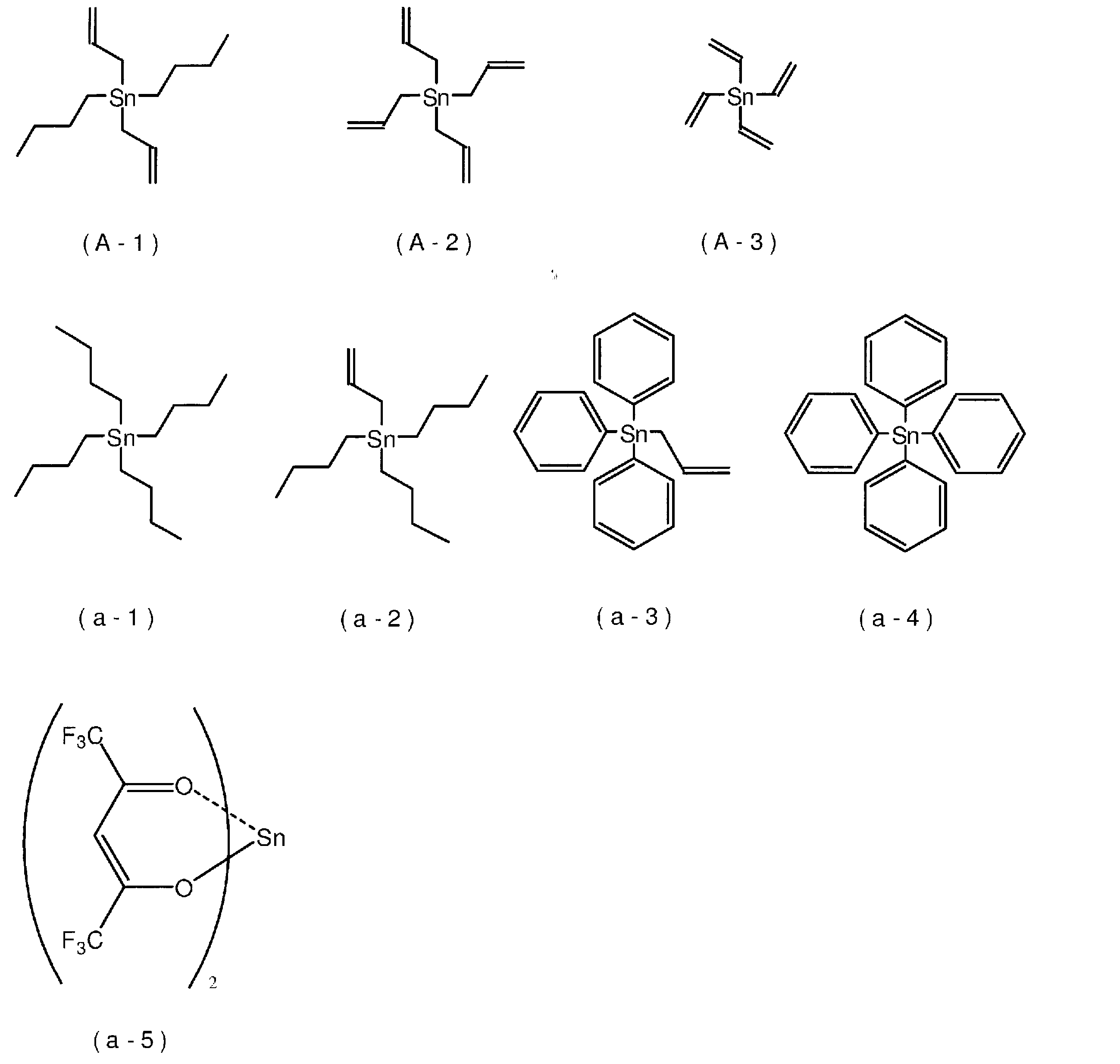
- A-1 Diallyldibutyltin
- A-2 Tetraallyltin
- A-3 Tetravinyltin a-1: Tetrabutyltin a-2: Allyltributyltin a-3: Allyltriphenyltin a-4: Tetraphenyltin a-5 : Bis (hexafluoroacetylacetonato) tin (Bis (acetylacetonato) tin)
- Example 1 LiPF 6 was dissolved at 1 M in a solvent in which EC and EMC were mixed at a volume ratio of 30:70, and diallyldibutyltin (A-1) was added to 1.0 mass%. A water electrolyte was obtained.
- LiNi 1/3 Co 1/3 Mn 1/3 O 2 having an ⁇ -NaFeO 2 type crystal structure as a positive electrode active material, acetylene black as a conductive agent, and PVDF as a binder are 94:
- a positive electrode active material layer containing a mass ratio of 3: 3 was laminated to produce a positive electrode.
- the negative electrode whose negative electrode active material is graphite was produced.
- a power generation element was produced by winding the positive electrode and the negative electrode through a polyolefin porous resin film separator. After inserting this power generation element into the aluminum case, the lid of the case was welded by laser welding. After injecting the obtained non-aqueous electrolyte through a liquid injection hole provided in the lid, the liquid injection hole was sealed to obtain a non-aqueous electrolyte secondary battery.
- Examples 2 to 3, Comparative Examples 1 to 5 The types of organotin compounds used were those shown in Table 1, or the same as in Example 1 except that no organotin compounds were used. Examples 2 to 3 and Comparative Examples 1 to 5 A water electrolyte and a non-aqueous electrolyte secondary battery were obtained.
- Example 4 to 11 Comparative Examples 6 to 7
- the nonaqueous electrolytes and nonaqueous electrolytes of Examples 4 to 11 and Comparative Examples 6 to 7 were the same as Example 1 except that the types and amounts of the organotin compounds used were those described in Table 3. A secondary battery was obtained. In Table 3, Comparative Example 1, Examples 2 and 3 are shown again.
- Example 12 to 13 The nonaqueous electrolytes and nonaqueous electrolyte secondary batteries of Examples 12 to 13 were obtained in the same manner as Example 1 except that the types and amounts of the organic tin compounds used were those shown in Table 4. . In Table 4, Comparative Example 1, Examples 2 and 3 are shown again.
- the non-aqueous electrolyte secondary batteries of Comparative Examples 1 to 3 and Examples 1 and 2 that were separately prepared were initialized at a charge voltage of 4.35 V and a discharge voltage of 2.75 V, and then disassembled in a discharged state. did. Thereafter, the positive electrode and the negative electrode were washed with DMC and vacuum-dried. Thereafter, X-ray photoelectron absorption spectroscopy analysis of the positive electrode (positive electrode mixture) and the negative electrode (negative electrode mixture) was performed.
- Table 5 shows the peak intensity (a) in the range from 530 eV to 534 eV and the peak intensity (b) in the range from 528 eV to less than 530 eV, and the ratio (a / b) thereof in the peak attributed to the O1s spectrum of the positive electrode.
- Table 6 shows the peak intensity (c) in the range of 686 eV or more and 689 eV or less, the peak intensity (d) in the range of 683 eV or more and less than 686 eV, and the ratio (c / d) thereof in the peak attributed to the F1s spectrum of the positive electrode. Show.
- Table 7 shows the peak intensity (e) in the range from 286 eV to 288 eV and the peak intensity (f) in the range from 284 eV to 286 eV, and the ratio (e / f) thereof, in the peak attributed to the C1s spectrum of the negative electrode. Show. Further, the content of tin in the positive electrode mixture and the negative electrode mixture was measured by high frequency inductively coupled plasma optical emission spectrometry (ICP). Table 8 shows the measurement results.
- ICP inductively coupled plasma optical emission spectrometry
- the organic tin compound contains two or more aliphatic hydrocarbon groups bonded to a tin atom and having an unsaturated bond, and the content of the organic tin compound is It turns out that the nonaqueous electrolyte secondary battery of each Example provided with the nonaqueous solvent which is 0.2 mass% or more has the charging / discharging cycle life excellent in both 0 degreeC and 45 degreeC. Further, as shown in Tables 5 to 8, it can be seen that the film formation amount and the tin content are large in the positive electrode and the negative electrode in the nonaqueous electrolyte secondary battery of each example. Thereby, it is guessed that the nonaqueous electrolyte secondary battery of each Example has a long charge / discharge cycle life in a wide temperature range.
- the present invention can be applied to electronic devices such as personal computers and communication terminals, non-aqueous electrolyte secondary batteries used as power sources for automobiles, and non-aqueous electrolytes for secondary batteries provided therein.
Landscapes
- Chemical & Material Sciences (AREA)
- Chemical Kinetics & Catalysis (AREA)
- Electrochemistry (AREA)
- General Chemical & Material Sciences (AREA)
- Engineering & Computer Science (AREA)
- Manufacturing & Machinery (AREA)
- Physics & Mathematics (AREA)
- Condensed Matter Physics & Semiconductors (AREA)
- General Physics & Mathematics (AREA)
- Inorganic Chemistry (AREA)
- Materials Engineering (AREA)
- Secondary Cells (AREA)
- Battery Electrode And Active Subsutance (AREA)
Abstract
特殊な化合物を用いなくとも広い温度範囲において充放電サイクルにおける容量維持率を高めることができる二次電池用非水電解質、この非水電解質を備える非水電解質二次電池、及び非水電解質二次電池の製造方法を提供する。本発明の一態様に係る二次電池用非水電解質は、非水溶媒に電解質塩が溶解する二次電池用非水電解質であって、スズ原子と結合し、かつ不飽和結合を有する2つ以上の脂肪族炭化水素基を有する有機スズ化合物を含有し、上記有機スズ化合物の含有量が、0.2質量%以上である。本発明の他の一態様にかかる非水電解質二次電池は、正極と、負極と、非水電解質とを備える非水電解質二次電池であって、上記非水電解質として、上記二次電池用非水電解質が用いられている。
Description
本発明は、二次電池用非水電解質、非水電解質二次電池、及び非水電解質二次電池の製造方法に関する。
リチウムイオン二次電池に代表される非水電解質二次電池は、エネルギー密度の高さから、パーソナルコンピュータ、通信端末等の電子機器、自動車などに多用されている。上記非水電解質二次電池は、一般的には、セパレータで電気的に隔離された一対の電極と、この電極間に介在する非水電解質とを有し、両電極間でイオンの受け渡しを行うことで充放電するよう構成される。
このような非水電解質二次電池においては、充放電サイクル特性等を向上させるために、非水電解質に有機スズ化合物を含有させる技術が開発されている(特許文献1、特許文献2及び特許文献3参照)。しかし、有機スズ化合物を含有させた従来の非水電解質においても、充放電サイクルにおける容量維持率の向上効果は十分と言えず、改善の余地がある。特に、従来の非水電解質は低温下における充放電サイクル寿命が短く、広い温度範囲において長い充放電サイクル寿命を有する非水電解質二次電池の開発が求められている。
なお、上記特許文献1においては、スズとケイ素又はゲルマニウムとを含む有機化合物や、ビス(アセチルアセトナート)スズ(Bis(acetylacetonato)tin)等、スズにβ-ジケトネート(β-diketonato)が配位された錯体を含有する非水電解質が提案されており、さらに、これらの化合物と他の有機スズ化合物とを併用することで効果が高まることが記載されている。上記特許文献1においては、上記他の有機スズ化合物として、0.1wt%のテトラブチルスズやテトラアリルスズが添加された実施例が示されているが、テトラブチルスズとテトラアリルスズとを用いた場合の効果の差異は表れていない(表2等参照)。また、上記技術は、必須の成分として特殊な錯体等を用いるものであるため、経済性などの点が懸念される。
本発明は、以上のような事情に基づいてなされたものであり、その目的は、特殊な化合物を用いなくとも広い温度範囲において充放電サイクルにおける容量維持率を高めることができる二次電池用非水電解質、この非水電解質を備える非水電解質二次電池、及び非水電解質二次電池の製造方法を提供することである。
本発明の一態様に係る二次電池用非水電解質は、非水溶媒に電解質塩が溶解する二次電池用非水電解質であって、スズ原子と結合し、かつ不飽和結合を有する2つ以上の脂肪族炭化水素基を有する有機スズ化合物を含有し、上記有機スズ化合物の含有量が、0.2質量%以上である。
本発明の他の一態様に係る非水電解質二次電池は、正極と、負極と、非水電解質とを備える非水電解質二次電池であって、上記非水電解質として、上記二次電池用非水電解質が用いられている。
本発明の他の一態様に係る非水電解質二次電池は、正極活物質及びスズを含む正極合材を有する正極と、負極と、非水電解質とを備える非水電解質二次電池であって、上記正極合材に対するX線光電子吸収分光分析のO1sスペクトルに帰属されるピークにおいて、530eV以上534eV以下の範囲のピーク強度の528eV以上530eV未満の範囲のピーク強度に対する比が1.2以上である。
本発明の他の一態様に係る非水電解質二次電池は、正極活物質、バインダーとしてのフッ素樹脂及びスズを含む正極合材を有する正極と、負極と、非水電解質とを備える非水電解質二次電池であって、上記正極合材に対するX線光電子吸収分光分析のF1sスペクトルに帰属されるピークにおいて、686eV以上689eV以下の範囲のピーク強度の683eV以上686eV未満の範囲のピーク強度に対する比が3.0以下である。
本発明の他の一態様に係る非水電解質二次電池は、負極活物質及びスズを含む負極合材を有する負極と、正極と、非水電解質とを備える非水電解質二次電池であって、
上記負極合材に対するX線光電子吸収分光分析のC1sスペクトルに帰属されるピークにおいて、286eV以上288eV以下の範囲のピーク強度の284eV以上286eV未満の範囲のピーク強度に対する比が0.6以上である。
上記負極合材に対するX線光電子吸収分光分析のC1sスペクトルに帰属されるピークにおいて、286eV以上288eV以下の範囲のピーク強度の284eV以上286eV未満の範囲のピーク強度に対する比が0.6以上である。
本発明の他の一態様に係る非水電解質二次電池の製造方法は、正極と、負極と、非水電解質とを備える非水電解質二次電池の製造方法であって、上記非水電解質として、上記二次電池用非水電解質を用いる。
本発明によれば、特殊な化合物を用いなくとも広い温度範囲において充放電サイクルにおける容量維持率を高めることができる二次電池用非水電解質、この非水電解質を備える非水電解質二次電池、及び非水電解質二次電池の製造方法を提供することができる。
以下、本発明の一実施形態に係る二次電池用非水電解質、非水電解質二次電池、及び非水電解質二次電池の製造方法について詳説する。
<二次電池用非水電解質>
本発明の一実施形態に係る二次電池用非水電解質(以下、単に「非水電解質」ということもある。)は、非水溶媒に電解質塩が溶解する二次電池用非水電解質であって、スズ原子と結合し、かつ不飽和結合を有する2つ以上の脂肪族炭化水素基を有する有機スズ化合物を含有する。
本発明の一実施形態に係る二次電池用非水電解質(以下、単に「非水電解質」ということもある。)は、非水溶媒に電解質塩が溶解する二次電池用非水電解質であって、スズ原子と結合し、かつ不飽和結合を有する2つ以上の脂肪族炭化水素基を有する有機スズ化合物を含有する。
<有機スズ化合物>
上記有機スズ化合物は、スズ原子と結合し、かつ不飽和結合を有する2つ以上の脂肪族炭化水素基を有する。上記有機スズ化合物は、通常、上記非水溶媒に溶解している。上記不飽和結合を有する脂肪族炭化水素基は、スズ原子から脱離しやすく、この基の脱離により、上記有機スズ化合物は、電極の表面に付着しやすくなり、皮膜を形成する。特に、上記有機スズ化合物は、複数の上記脂肪族炭化水素基を有するため、皮膜形成機能等に優れる。このため、上記有機スズ化合物を含む非水電解質が用いられた二次電池においては、上記スズ原子を含む皮膜により、充放電サイクルにおける容量維持率を高めることができ、低温下においても長い充放電サイクル寿命を発揮することができる。
上記有機スズ化合物は、スズ原子と結合し、かつ不飽和結合を有する2つ以上の脂肪族炭化水素基を有する。上記有機スズ化合物は、通常、上記非水溶媒に溶解している。上記不飽和結合を有する脂肪族炭化水素基は、スズ原子から脱離しやすく、この基の脱離により、上記有機スズ化合物は、電極の表面に付着しやすくなり、皮膜を形成する。特に、上記有機スズ化合物は、複数の上記脂肪族炭化水素基を有するため、皮膜形成機能等に優れる。このため、上記有機スズ化合物を含む非水電解質が用いられた二次電池においては、上記スズ原子を含む皮膜により、充放電サイクルにおける容量維持率を高めることができ、低温下においても長い充放電サイクル寿命を発揮することができる。
上記有機スズ化合物は、スズ原子と結合し、かつ不飽和結合を有する2つ以上の脂肪族炭化水素基を有する限り特に限定されないが、下記式(1)で表される化合物であることが好ましい。

式(1)中、nは、2~4の整数である。複数のR1は、それぞれ独立して、不飽和結合を有する炭素数2~6の脂肪族炭化水素基である。上記脂肪族炭化水素基が有する水素原子の一部又は全部は、置換基で置換されていてもよい。R2は、不飽和結合を有する脂肪族炭化水素基以外の炭素数1~6の炭化水素基である。上記炭化水素基が有する水素原子の一部又は全部は、置換基で置換されていてもよい。nが2の場合、複数のR2は、それぞれ独立して上記定義を満たす。
上記R1で表される不飽和結合を有する炭素数2~6の脂肪族炭化水素基としては、
ビニル基、アリル基、1-プロペニル基、1-ブテニル基、2-ブテニル基、1-ペンテニル基、1-ヘキセニル基、1,3-ブタジエニル基、1,3,5-ヘキサトリエニル基等のアルケニル基;
エチニル基、1-プロピニル基、2-プロピニル基等のアルキニル基;
シクロペンテニル基、シクロヘキセニル基等のシクロアルケニル基
等を挙げることができる。
ビニル基、アリル基、1-プロペニル基、1-ブテニル基、2-ブテニル基、1-ペンテニル基、1-ヘキセニル基、1,3-ブタジエニル基、1,3,5-ヘキサトリエニル基等のアルケニル基;
エチニル基、1-プロピニル基、2-プロピニル基等のアルキニル基;
シクロペンテニル基、シクロヘキセニル基等のシクロアルケニル基
等を挙げることができる。
上記R1で表される脂肪族炭化水素基が有していてもよい置換基としては、ハロゲン原子、アルコキシ基、ヒドロキシ基、カルボキシ基、シアノ基、-NR2(Rは、それぞれ独立して、水素原子又は炭素数1~5のアルキル基である。但し、2つのRが互いに結合して環構造を形成していてもよい)で表される基等を挙げることができる。上記ハロゲン原子としては、フッ素原子、塩素原子、臭素原子、ヨウ素原子等を挙げることができる。上記アルコキシ基としては、メトキシ基、エトキシ基等の炭素数1~5のアルコキシ基等を挙げることができる。
上記R1としては、アルケニル基が好ましく、下記式(2)で表される基がより好ましい。このような不飽和二重結合がスズ原子に近い位置にある脂肪族炭化水素基は、脱離性が高い。このため、下記式(2)で表される基を有する有機スズ化合物を用いることにより、充放電サイクル寿命をより長くすることができる。

式(2)中、R3及びR4は、それぞれ独立して、水素原子又は炭素数1~3の炭化水素基である。mは、0又は1である。
上記R3及びR4で表される炭素数1~3の炭化水素基としては、メチル基、エチル基、n-プロピル基、及びi-プロピル基を挙げることができる。上記R3及びR4としては、水素原子が好ましい。すなわち、R1で表される基としては、上記式(2)で表される基の中でも、ビニル基及びアリル基が好ましい。
上記R2で表される炭素数1~6の炭化水素基は、不飽和結合を有する脂肪族炭化水素基以外の炭化水素基である。上記R2で表される炭素数1~6の炭化水素基としては、炭素数1~6の飽和脂肪族炭化水素基や、フェニル基を挙げることができる。上記炭素数1~6の飽和脂肪族炭化水素基としては、炭素数1~6のアルキル基や、炭素数3~6のシクロアルキル基を挙げることができる。
上記炭素数1~6のアルキル基としては、メチル基、エチル基、n-プロピル基、i-プロピル基、n-ブチル基等を挙げることができる。
上記炭素数3~6のシクロアルキル基としては、シクロプロピル基、シクロブチル基等を挙げることができる。
上記R2で表される炭化水素基が有していてもよい置換基は、上記R1で表される脂肪族炭化水素基が有していてもよい置換基として例示したもの等をあげることができる。
上記R2で表される基としては、炭素数1~6のアルキル基が好ましい。
上記nは、不飽和結合を有する炭素数2~6の脂肪族炭化水素基の数を表し、2~4の整数である。但し、上記有機スズ化合物は、入手のし易さなどの経済性等を特に考慮すると、n=2である有機スズ化合物、及びn=4である有機スズ化合物が好ましい。また、皮膜形成性、充放電サイクルにおける容量維持率を高める効果等を考慮すると、上記有機スズ化合物は、n=3である有機スズ化合物、及び、n=4である有機スズ化合物が好ましい。上記nは、4がより好ましい。
上記有機スズ化合物としては、ジビニルジメチルスズ、ジビニルジエチルスズ、ジビニルジプロピルスズ、ジビニルジブチルスズ、ジビニルジペンチルスズ、トリビニルメチルスズ、トリビニルエチルスズ、トリビニルプロピルスズ、トリビニルブチルスズ、トリビニルペンチルスズ、テトラビニルスズ、ジアリルジメチルスズ、ジアリルジエチルスズ、ジアリルジプロピルスズ、ジアリルジブチルスズ、ジアリルジペンチルスズ、トリアリルメチルスズ、トリアリルエチルスズ、トリアリルプロピルスズ、トリアリルブチルスズ、トリアリルペンチルスズ、テトラアリルスズ、アリルビニルジメチルスズ、ジアリルジビニルスズ、ジプロペニルジプロピルスズ、テトラプロペニルスズ、ジブテニルジブチルスズ、テトラブテニルスズ等を挙げることができる。
これらの中でも、複数のビニル基を有する有機スズ化合物及び複数のアリル基を有する有機スズ化合物が好ましく、テトラビニルスズ、ジアリルジブチルスズ及びテトラアリルスズがより好ましく、テトラビニルスズ及びテトラアリルスズがさらに好ましい。
当該非水電解質における上記有機スズ化合物の含有量の下限としては、0.2質量%であり、0.3質量%が好ましく、0.5質量%がより好ましい。上記有機スズ化合物がテトラビニルスズ等の場合、上記下限としては1質量%がさらに好ましい。上記有機スズ化合物の含有量を上記下限以上とすることで、充放電サイクルにおける容量維持率を高めることができる。
当該非水電解質における上記有機スズ化合物の含有量の上限としては、特に制限されないが、5質量%が好ましく、3質量%がより好ましく、2質量%がさらに好ましい。上記有機スズ化合物がテトラアリルスズ等の場合、上記上限としては1.5質量%がよりさらに好ましく、1質量%が特に好ましい。上記有機スズ化合物の含有量を上記上限以下とすることで、充放電サイクルにおける容量維持率をより高めることができる。
<非水溶媒>
上記非水溶媒としては、一般的な二次電池用非水電解質の非水溶媒として通常用いられる公知の非水溶媒を用いることができる。上記非水溶媒としては、環状カーボネート、鎖状カーボネート、エステル、エーテル、アミド、スルホン、ラクトン、ニトリル等を挙げることができる。これらの中でも、環状カーボネート又は鎖状カーボネートを少なくとも用いることが好ましく、環状カーボネートと鎖状カーボネートとを併用することがより好ましい。環状カーボネートと鎖状カーボネートとを併用する場合、環状カーボネートと鎖状カーボネートとの体積比(環状カーボネート:鎖状カーボネート)としては、特に限定されないが、例えば5:95以上50:50以下とすることが好ましい。
上記非水溶媒としては、一般的な二次電池用非水電解質の非水溶媒として通常用いられる公知の非水溶媒を用いることができる。上記非水溶媒としては、環状カーボネート、鎖状カーボネート、エステル、エーテル、アミド、スルホン、ラクトン、ニトリル等を挙げることができる。これらの中でも、環状カーボネート又は鎖状カーボネートを少なくとも用いることが好ましく、環状カーボネートと鎖状カーボネートとを併用することがより好ましい。環状カーボネートと鎖状カーボネートとを併用する場合、環状カーボネートと鎖状カーボネートとの体積比(環状カーボネート:鎖状カーボネート)としては、特に限定されないが、例えば5:95以上50:50以下とすることが好ましい。
上記環状カーボネートとしては、エチレンカーボネート(EC)、プロピレンカーボネート(PC)、ブチレンカーボネート(BC)、ビニレンカーボネート(VC)、ビニルエチレンカーボネート(VEC)、クロロエチレンカーボネート、フルオロエチレンカーボネート(FEC)、ジフルオロエチレンカーボネート(DFEC)、スチレンカーボネート、カテコールカーボネート、1-フェニルビニレンカーボネート、1,2-ジフェニルビニレンカーボネート等を挙げることができ、これらの中でもECが好ましい。
上記鎖状カーボネートとしては、ジエチルカーボネート(DEC)、ジメチルカーボネート(DMC)、エチルメチルカーボネート(EMC)、ジフェニルカーボネート等を挙げることができ、これらの中でもEMCが好ましい。
<電解質塩>
上記電解質塩としては、一般的な二次電池用非水電解質の電解質塩として通常用いられる公知の電解質塩を用いることができる。上記電解質塩としては、リチウム塩、ナトリウム塩、カリウム塩、マグネシウム塩、オニウム塩等を挙げることができるが、リチウム塩が好ましい。
上記電解質塩としては、一般的な二次電池用非水電解質の電解質塩として通常用いられる公知の電解質塩を用いることができる。上記電解質塩としては、リチウム塩、ナトリウム塩、カリウム塩、マグネシウム塩、オニウム塩等を挙げることができるが、リチウム塩が好ましい。
上記リチウム塩としては、LiPF6、LiPO2F2、LiBF4、LiClO4、LiN(SO2F)2等の無機リチウム塩、LiSO3CF3、LiN(SO2CF3)2、LiN(SO2C2F5)2、LiN(SO2CF3)(SO2C4F9)、LiC(SO2CF3)3、LiC(SO2C2F5)3等のフッ化炭化水素基を有するリチウム塩などを挙げることができる。これらの中でも、無機リチウム塩が好ましく、LiPF6がより好ましい。
当該非水電解質における上記電解質塩の含有量の下限としては、0.1Mが好ましく、0.3Mがより好ましく、0.5Mがさらに好ましく、0.7Mが特に好ましい。一方、この上限としては、特に限定されないが、2.5Mが好ましく、2Mがより好ましく、1.5Mがさらに好ましい。
<他の成分>
当該非水電解質は、本発明の効果を阻害しない限り、上記有機スズ化合物、上記非水溶媒及び上記電解質塩以外の他の成分を含有していてもよい。他の成分としては、従来の二次電池用非水電解質に添加される公知の添加剤等を挙げることができる。但し、これらの他の成分の含有量の上限としては、5質量%、さらには1質量%、よりさらには0.1質量%が好ましいこともある。特に、当該非水電解質における上記有機スズ化合物以外の他の有機スズ化合物の含有量としては、0.05質量%未満であることが好ましい。この他の有機スズ化合物の含有量の上限としては、0.01質量%がより好ましく、0.001質量%以下がさらに好ましく、他の有機スズ化合物は、実質的に含有されていないことが特に好ましい。上記他の有機スズ化合物の含有量が、0.05質量%以上の場合、非水電解質のイオン伝導性や、電極表面に形成される上記特定の有機スズ化合物に由来する皮膜の物性に影響を与え、充放電サイクル寿命を低下させる場合がある。また、上記有機スズ化合物と併用しても容量維持率の改善効果を示さない他の有機スズ化合物をさらに含有させた場合、コスト高を招く場合がある。
当該非水電解質は、本発明の効果を阻害しない限り、上記有機スズ化合物、上記非水溶媒及び上記電解質塩以外の他の成分を含有していてもよい。他の成分としては、従来の二次電池用非水電解質に添加される公知の添加剤等を挙げることができる。但し、これらの他の成分の含有量の上限としては、5質量%、さらには1質量%、よりさらには0.1質量%が好ましいこともある。特に、当該非水電解質における上記有機スズ化合物以外の他の有機スズ化合物の含有量としては、0.05質量%未満であることが好ましい。この他の有機スズ化合物の含有量の上限としては、0.01質量%がより好ましく、0.001質量%以下がさらに好ましく、他の有機スズ化合物は、実質的に含有されていないことが特に好ましい。上記他の有機スズ化合物の含有量が、0.05質量%以上の場合、非水電解質のイオン伝導性や、電極表面に形成される上記特定の有機スズ化合物に由来する皮膜の物性に影響を与え、充放電サイクル寿命を低下させる場合がある。また、上記有機スズ化合物と併用しても容量維持率の改善効果を示さない他の有機スズ化合物をさらに含有させた場合、コスト高を招く場合がある。
上記他の有機スズ化合物としては、有機スズスルホネート、有機スズアルコシキド、有機スズカルボキシレート、下記式(3)で表される化合物、その他の有機スズ錯体、有機スズ塩等を挙げることができる。
SnX2 (3)
式(3)中、Xは、β-ジケトナト(β-diketonato)である。
式(3)中、Xは、β-ジケトナト(β-diketonato)である。
上記式(3)で表される化合物としては、ビス(アセチルアセトナト)スズ、ビス(ヘキサフルオロアセチルアセトナト)スズ、ビス(2,2,6,6-テトラメチル-3,5-ヘプタンジオナト)スズ、ビス(2,2-ジメチル-3,5-ヘキサンジオナト)スズ、ビス(ベンゾイルアセトナト)スズ、ビス(メチルアセチルアセトナト)スズ、ビス(エチルアセチルアセトナト)スズ、ビス(プロピルアセチルアセトナト)スズ、ビス(ブチルアセチルアセトナト)スズ等を挙げることができる。
上記他の有機スズ化合物の中でも、上記式(3)で表される化合物を含有しない、又は下記式(3)で表される化合物の含有量が0.05質量%未満であることが好ましい。この含有量の上限としては、0.01質量%がより好ましく、0.001質量%以下がさらに好ましい。上記化合物の含有量が、0.05質量%以上の場合、電解液のイオン伝導性や、電極表面に形成される上記特定の有機スズ化合物に由来する皮膜の物性に影響を与え、充放電サイクル寿命を低下させる場合がある。また、実施例で示すように、上記有機スズ化合物と上記式(3)で表される化合物とを併用しても、上記有機スズ化合物のみを用いた場合と比べて、容量維持率がさらに改善されるものではない。従って、経済的な観点などから、上記式(3)で表される化合物の含有量は少ないほど好ましい。上記化合物の含有量が0.05質量%以上の場合、コスト高をきたす場合がある。
当該非水電解質は、上記非水溶媒に上記電解質塩、及び所定量の上記有機スズ化合物を添加し、溶解させることにより得ることができる。
<非水電解質二次電池>
本発明の一実施形態に係る非水電解質二次電池は、正極と、負極と、非水電解質とを備える。上記正極及び負極は、通常、セパレータを介して積層又は巻回により交互に重畳された発電要素を形成する。この発電要素はケースに収納され、このケース内に上記非水電解質が充填される。当該非水電解質二次電池においては、非水電解質として、上述した二次電池用非水電解質が用いられている。非水電解質は、正極と負極との間に介在する。また、上記ケースとしては、非水電解質二次電池のケースとして通常用いられる公知のアルミニウムケース等を用いることができる。
本発明の一実施形態に係る非水電解質二次電池は、正極と、負極と、非水電解質とを備える。上記正極及び負極は、通常、セパレータを介して積層又は巻回により交互に重畳された発電要素を形成する。この発電要素はケースに収納され、このケース内に上記非水電解質が充填される。当該非水電解質二次電池においては、非水電解質として、上述した二次電池用非水電解質が用いられている。非水電解質は、正極と負極との間に介在する。また、上記ケースとしては、非水電解質二次電池のケースとして通常用いられる公知のアルミニウムケース等を用いることができる。
当該非水電解質二次電池によれば、スズ原子と結合し、かつ不飽和結合を有する2つ以上の脂肪族炭化水素基を有する有機スズ化合物を所定量含有する非水電解質を用いることで、広い温度範囲において充放電サイクルにおける容量維持率を高めることができる。
<正極>
上記正極は、正極集電体、及びこの正極集電体に直接又は中間層を介して配される正極活物質層を有する。
上記正極は、正極集電体、及びこの正極集電体に直接又は中間層を介して配される正極活物質層を有する。
上記正極集電体は、導電性を有する。集電体の材質としては、アルミニウム、チタン、タンタル、ステンレス鋼等の金属又はそれらの合金が用いられる。これらの中でも、耐電位性、導電性の高さ及びコストのバランスからアルミニウム及びアルミニウム合金が好ましい。また、正極集電体の形成形態としては、箔、蒸着膜等が挙げられ、コストの面から箔が好ましい。つまり、正極集電体としてはアルミニウム箔が好ましい。なお、アルミニウム又はアルミニウム合金としては、JIS-H-4000(2014年)に規定されるA1085P、A3003P等が例示できる。
中間層は、正極集電体の表面の被覆層であり、炭素粒子等の導電性粒子を含むことで正極集電体と正極活物質層との接触抵抗を低減する。中間層の構成は特に限定されず、例えば樹脂バインダー及び導電性粒子を含有する組成物により形成できる。なお、「導電性」を有するとは、JIS-H-0505(1975年)に準拠して測定される体積抵抗率が107Ω・cm以下であることを意味し、「非導電性」とは、上記体積抵抗率が107Ω・cm超であることを意味する。
正極活物質層は、正極活物質を含むいわゆる正極合材から形成される。また、正極活物質層を形成する正極合材は、必要に応じて導電剤、バインダー(結着剤)、増粘剤、フィラー等の任意成分を含む。
上記正極活物質としては、例えばLixMOy(Mは少なくとも一種の遷移金属を表す)で表される複合酸化物(層状のα―NaFeO2型結晶構造を有するLixCoO2,LixNiO2,LixMnO3,LixNiαCo(1-α)O2,LixNiαMnβCo(1-α-β)O2等、スピネル型結晶構造を有するLixMn2O4,LixNiαMn(2-α)O4等)、LiwMex(XOy)z(Meは少なくとも一種の遷移金属を表し、Xは例えばP、Si、B、V等を表す)で表されるポリアニオン化合物(LiFePO4,LiMnPO4,LiNiPO4,LiCoPO4,Li3V2(PO4)3,Li2MnSiO4,Li2CoPO4F等)が挙げられる。これらの化合物中の元素又はポリアニオンは、他の元素又はアニオン種で一部が置換されていてもよい。正極活物質層においては、これら化合物の1種を単独で用いてもよく、2種以上を混合して用いてもよい。
上記正極合材(正極活物質層)における正極活物質の含有量の下限としては、50質量%が好ましく、70質量%がより好ましく、80質量%がさらに好ましい。一方、正極活物質の含有量の上限としては、特に限定されないが、例えば99質量%が好ましく、95質量%がより好ましい。正極活物質の含有量を上記範囲とすることで、非水電解質二次電池の電気容量を高めることなどができる。
上記導電剤としては、電池性能に悪影響を与えない導電性材料であれば特に限定されない。このような導電剤としては、天然又は人造の黒鉛、ファーネスブラック、アセチレンブラック、ケッチェンブラック等のカーボンブラック、金属、導電性セラミックスなどが挙げられる。導電剤の形状としては、粉状、繊維状等が挙げられる。
上記バインダー(結着剤)としては、フッ素樹脂(ポリテトラフルオロエチレン(PTFE)、ポリフッ化ビニリデン(PVDF)等)、ポリエチレン、ポリプロピレン、ポリイミド等の熱可塑性樹脂;エチレン-プロピレン-ジエンゴム(EPDM)、スルホン化EPDM、スチレンブタジエンゴム(SBR)、フッ素ゴム等のエラストマー;多糖類高分子などが挙げられる。
上記正極合材(正極活物質層)におけるバインダーの含有量の下限としては、1質量%が好ましく、2質量%がより好ましい。一方、上記含有量の上限としては、10質量%が好ましく、5質量%がより好ましい。バインダーの含有量を上記範囲とすることで、活物質を安定して保持することができる。
上記増粘剤としては、カルボキシメチルセルロース(CMC)、メチルセルロース等の多糖類高分子が挙げられる。また、増粘剤がリチウムと反応する官能基を有する場合、予めメチル化等によりこの官能基を失活させておくことが好ましい。
上記フィラーとしては、電池性能に悪影響を与えないものであれば特に限定されない。フィラーの主成分としては、ポリプロピレン、ポリエチレン等のポリオレフィン、シリカ、アルミナ、ゼオライト、ガラス、炭素などが挙げられる。
当該非水電解質二次電池は、上記特定の有機スズ化合物を含む非水電解質が用いられているため、上記正極合材(正極活物質層)には、上記有機スズ化合物に由来するスズが含まれる。上述のように、正極活物質層表面に、上記有機スズ化合物に由来するスズを含む皮膜が形成されるためである。なお、非水電解質の注入後に初期化成を行うことなどにより、上記皮膜の形成が進行する。
上記正極合材(正極活物質層)に対するX線光電子吸収分光分析のO1sスペクトルに帰属されるピークにおいて、530eV以上534eV以下の範囲のピーク強度(a)の528eV以上530eV未満の範囲のピーク強度(b)に対する比(a/b)が1.2以上であることが好ましい。上記O1sスペクトルに帰属されるピークにおいて、上記530eV以上534eV以下の範囲のピーク(a)は、主に正極表面の皮膜(当該非水二次電池においては、例えば酸化スズを含む皮膜)に由来するピークである。一方、上記528eV以上530eV未満の範囲のピーク(b)は、正極活物質に由来するピークである。すなわち、530eV以上534eV以下の範囲のピーク強度(a)の528eV以上530eV未満の範囲のピーク強度(b)に対する比(a/b)が1.2以上であるということは、正極表面に十分な量の皮膜が形成されていることを意味する。このように正極表面に十分な皮膜が形成されていることにより、広い温度範囲において充放電サイクルにおける容量維持率をより高めることができる。上記比(a/b)としては、1.25以上がより好ましい。一方、この比(a/b)の上限としては、特に限定されないが、例えば3.0であり、2.0が好ましく、1.5がより好ましい。
また、上記正極合材(正極活物質層)が、バインダーとしてフッ素樹脂を含む場合、上記正極合材に対するX線光電子吸収分光分析のF1sスペクトルに帰属されるピークにおいて、686eV以上689eV以下の範囲のピーク強度(c)の683eV以上686eV未満の範囲のピーク強度(d)に対する比(c/d)が3.0以下であることが好ましい。上記F1sスペクトルに帰属されるピークにおいて、上記686eV以上689eV以下の範囲のピーク(c)は、バインダーとしてのフッ素樹脂(PVDF等)に由来するピークである。一方、上記683eV以上686eV未満の範囲のピーク(d)は、主に正極表面の皮膜(当該非水二次電池においては、例えばフッ化スズを含む皮膜)に由来するピークである。すなわち、686eV以上689eV以下の範囲のピーク強度(c)の683eV以上686eV未満の範囲のピーク強度(d)に対する比(c/d)が3.0以下であることは、十分な量の皮膜が正極表面に形成されていることを意味する。このように正極表面に十分な皮膜が形成されていることにより、広い温度範囲において充放電サイクルにおける容量維持率をより高めることができる。上記比(c/d)としては、2.0以下がより好ましい。一方、この比(c/d)の下限としては、特に限定されないが、例えば0.1であり、0.5が好ましく、0.8がより好ましい。
上記正極合材(正極活物質層)におけるスズの含有量の下限としては、0.01質量%が好ましく、0.03質量%がより好ましい。正極合材におけるスズの含有量が上記上限以上であることで、広い温度範囲において充放電サイクルにおける容量維持率をより高めることができる。一方、この含有量の上限としては特に限定されないが、例えば0.2質量%であり、0.1質量%であってもよい。
<負極>
上記負極は、負極集電体、及びこの負極集電体に直接又は中間層を介して配される負極活物質層を有する。上記中間層は正極の中間層と同様の構成とすることができる。
上記負極は、負極集電体、及びこの負極集電体に直接又は中間層を介して配される負極活物質層を有する。上記中間層は正極の中間層と同様の構成とすることができる。
上記負極集電体は、正極集電体と同様の構成とすることができるが、材質としては、銅、ニッケル、ステンレス鋼、ニッケルメッキ鋼等の金属又はそれらの合金が用いられ、銅又は銅合金が好ましい。つまり、負極集電体としては銅箔が好ましい。銅箔としては、圧延銅箔、電解銅箔等が例示される。
負極活物質層は、負極活物質を含むいわゆる負極合材から形成される。また、負極活物質層を形成する負極合材は、必要に応じて導電剤、バインダー(結着剤)、増粘剤、フィラー等の任意成分を含む。導電剤、結着剤、増粘剤、フィラー等の任意成分は、正極活物質層と同様のものを用いることができる。
負極活物質としては、通常、リチウムイオンを吸蔵及び放出することができる材質が用いられる。具体的な負極活物質としては、例えばSi、Sn等の金属又は半金属;Si酸化物、Sn酸化物等の金属酸化物又は半金属酸化物;ポリリン酸化合物;黒鉛、非晶質炭素(易黒鉛化炭素又は難黒鉛化性炭素)等の炭素材料などが挙げられる。
さらに、負極合材(負極活物質層)は、B、N、P、F、Cl、Br、I等の典型非金属元素、Li、Na、Mg、Al、K、Ca、Zn、Ga、Ge等の典型金属元素、Sc、Ti、V、Cr、Mn、Fe、Co、Ni、Cu、Mo、Zr、Ta、Hf、Nb、W等の遷移金属元素を含有してもよい。
当該非水電解質二次電池は、上記特定の有機スズ化合物を含む非水電解質が用いられているため、上記正極と同様に、上記負極合材(負極活物質層)には、上記有機スズ化合物に由来するスズが含まれる。負極活物質表面にも、上記有機スズ化合物に由来するスズを含む皮膜が形成されるためである。なお、正極側と同様、非水電解質の注入後に初期化成を行うことなどにより、負極においても上記皮膜の形成が進行する。
上記負極合材(負極活物質層)に対するX線光電子吸収分光分析のC1sスペクトルに帰属されるピークにおいて、286eV以上288eV以下の範囲のピーク強度(e)の284eV以上286eV未満の範囲のピーク強度(f)に対する比(e/f)が0.6以上であることが好ましい。上記C1sスペクトルに帰属されるピークにおいて、上記286eV以上288eV以下の範囲のピーク(e)は、主に負極表面の皮膜(当該非水二次電池においては、例えば有機スズポリマーを含む皮膜)に由来するピークである。一方、上記284eV以上286eV未満の範囲のピーク(f)は、負極活物質に由来するピークである。すなわち、284eV以上286eV以下の範囲のピーク強度(e)の284eV以上286eV未満の範囲のピーク強度(f)に対する比(e/f)が0.6以上であるということは、負極表面に十分な量の皮膜が形成されていることを意味する。このように負極表面に十分な皮膜が形成されていることにより、広い温度範囲において充放電サイクルにおける容量維持率をより高めることができる。上記比(e/f)としては、0.7以上がより好ましい。一方、この比(a/b)の上限としては、特に限定されないが、例えば3.0であり、2.0が好ましく、1.5がより好ましい。
上記負極合材(負極活物質層)におけるスズの含有量の下限としては、0.05質量%が好ましく、0.1質量%がより好ましい。負極合材におけるスズの含有量が上記上限以上であることで、広い温度範囲において充放電サイクルにおける容量維持率をより高めることができる。一方、この含有量の上限としては特に限定されないが、例えば0.5質量%であり、0.3質量%であってもよい。
なお、本発明における正極合材(正極活物質層)、又は負極合材(負極活物質層)のX線光電子吸収分光分析は、次の手順及び条件にて行う。
まず、非水電解質二次電池を、0.1Cの電流で、電池電圧2.75Vに至るまで定電流放電を行い、放電状態とする。その後、露点-60℃以下のアルゴン雰囲気中で非水電解質二次電池を解体して、正極又は負極を取り出し、DMCを用いて正極又は負極に付着した非水電解液質を十分に洗浄し、室温にて一昼夜の間真空乾燥する。その後、正極又は負極を所定サイズ(例えば2×2cm)に切り出し、X線光電子吸収分光分析に供する。
X線光電子吸収分光分析に使用する装置及び測定条件は以下のとおりである。
装置:KRATOS ANALYTICAL社の「AXIS NOVA」
X線源:単色化Al Kα
加速電圧:15kV
分析面積:700μm×300μm
測定範囲:C1s=272~300eV、O1s=522~543eV、P2p=120~147eV、F1s=676~695eV
測定間隔:0.1eV
積算回数:C1s=8回、O1s=8回、P2p=15回、F1s=5回
なお、スペクトルデータは、C1sスペクトルにおける最大強度が284.8eVとなるようにキャリブレーションを実施する。
まず、非水電解質二次電池を、0.1Cの電流で、電池電圧2.75Vに至るまで定電流放電を行い、放電状態とする。その後、露点-60℃以下のアルゴン雰囲気中で非水電解質二次電池を解体して、正極又は負極を取り出し、DMCを用いて正極又は負極に付着した非水電解液質を十分に洗浄し、室温にて一昼夜の間真空乾燥する。その後、正極又は負極を所定サイズ(例えば2×2cm)に切り出し、X線光電子吸収分光分析に供する。
X線光電子吸収分光分析に使用する装置及び測定条件は以下のとおりである。
装置:KRATOS ANALYTICAL社の「AXIS NOVA」
X線源:単色化Al Kα
加速電圧:15kV
分析面積:700μm×300μm
測定範囲:C1s=272~300eV、O1s=522~543eV、P2p=120~147eV、F1s=676~695eV
測定間隔:0.1eV
積算回数:C1s=8回、O1s=8回、P2p=15回、F1s=5回
なお、スペクトルデータは、C1sスペクトルにおける最大強度が284.8eVとなるようにキャリブレーションを実施する。
<セパレータ>
上記セパレータの材質としては、例えば織布、不織布、多孔質樹脂フィルム等が用いられる。これらの中でも多孔質樹脂フィルムが好ましい。多孔質樹脂フィルムの主成分としては、強度の観点から例えばポリエチレン、ポリプロピレン等のポリオレフィンが好ましい。また、これらの樹脂とアラミドやポリイミド等の樹脂とを複合した多孔質樹脂フィルムを用いてもよい。
上記セパレータの材質としては、例えば織布、不織布、多孔質樹脂フィルム等が用いられる。これらの中でも多孔質樹脂フィルムが好ましい。多孔質樹脂フィルムの主成分としては、強度の観点から例えばポリエチレン、ポリプロピレン等のポリオレフィンが好ましい。また、これらの樹脂とアラミドやポリイミド等の樹脂とを複合した多孔質樹脂フィルムを用いてもよい。
<非水電解質二次電池の製造方法>
本発明の一実施形態に係る非水電解質二次電池の製造方法は、正極と、負極と、非水電解質とを備える非水電解質二次電池の製造方法であって、上記非水電解質として、当該二次電池用非水電解質を用いることを特徴とする。当該製造方法は、例えば、正極と負極とを収容するケースに非水電解質を注入する工程を備える。
本発明の一実施形態に係る非水電解質二次電池の製造方法は、正極と、負極と、非水電解質とを備える非水電解質二次電池の製造方法であって、上記非水電解質として、当該二次電池用非水電解質を用いることを特徴とする。当該製造方法は、例えば、正極と負極とを収容するケースに非水電解質を注入する工程を備える。
上記注入は、公知の方法により行うことができる。注入後、注入口を封止し、初期化成を行うことで、非水電解質二次電池を得ることができる。当該製造方法によって得られる非水電解質二次電池を構成する各要素についての詳細は上述したとおりである。当該非水電解質二次電池の製造方法によれば、スズ原子と結合し、かつ不飽和結合を有する2つ以上の脂肪族炭化水素基を有する有機スズ化合物を所定量含有する非水電解質を用いることで、広い温度範囲において充放電サイクルにおける容量維持率が高い非水電解質二次電池を製造することができる。
<その他の実施形態>
本発明は上記実施形態に限定されるものではなく、上記態様の他、種々の変更、改良を施した態様で実施することができる。なお、上述した、正極合材に対するX線光電子吸収分光分析のO1sスペクトルに帰属されるピークにおいて、530eV以上534eV以下の範囲のピーク強度の528eV以上530eV未満の範囲のピーク強度に対する比が1.2以上である非水電解質二次電池(α)や、正極合材に対するX線光電子吸収分光分析のF1sスペクトルに帰属されるピークにおいて、686eV以上689eV以下の範囲のピーク強度の683eV以上686eV未満の範囲のピーク強度に対する比が3.0以下である非水電解質二次電池(β)においては、充填されている非水電解質は特に限定されない。すなわち、上記非水電解質二次電池(α)や非水電解質二次電池(β)に充填されている非水電解質は、スズ原子と結合し、かつ不飽和結合を有する2つ以上の脂肪族炭化水素基を有する有機スズ化合物を含有していなくてもよいし、上記有機スズ化合物の含有量が、0.2質量%未満であってもよい。
本発明は上記実施形態に限定されるものではなく、上記態様の他、種々の変更、改良を施した態様で実施することができる。なお、上述した、正極合材に対するX線光電子吸収分光分析のO1sスペクトルに帰属されるピークにおいて、530eV以上534eV以下の範囲のピーク強度の528eV以上530eV未満の範囲のピーク強度に対する比が1.2以上である非水電解質二次電池(α)や、正極合材に対するX線光電子吸収分光分析のF1sスペクトルに帰属されるピークにおいて、686eV以上689eV以下の範囲のピーク強度の683eV以上686eV未満の範囲のピーク強度に対する比が3.0以下である非水電解質二次電池(β)においては、充填されている非水電解質は特に限定されない。すなわち、上記非水電解質二次電池(α)や非水電解質二次電池(β)に充填されている非水電解質は、スズ原子と結合し、かつ不飽和結合を有する2つ以上の脂肪族炭化水素基を有する有機スズ化合物を含有していなくてもよいし、上記有機スズ化合物の含有量が、0.2質量%未満であってもよい。
また、例えば、上記正極又は負極において、中間層を設けなくてもよい。また、例えば、上記非水電解質としてポリマー固体電解質を用いる場合、本発明の非水電解質二次電池の製造方法において、上述した注入工程を備えなくてもよい。
図1に、本発明の一実施形態である矩形状の非水電解質二次電池1の概略図を示す。なお、同図は、容器内部を透視した図としている。図1に示す非水電解質二次電池1は、電極体2が電池容器3に収納されている。電極体2は、正極活物質を備える正極と、負極活物質を備える負極とが、セパレータを介して捲回されることにより形成されている。正極は、正極リード4’を介して正極端子4と電気的に接続され、負極は、負極リード5’を介して負極端子5と電気的に接続されている。
本発明に係る非水電解質二次電池の構成については特に限定されるものではなく、円筒型電池、角型電池(矩形状の電池)、扁平型電池等が一例として挙げられる。本発明は、上記の非水電解質二次電池を複数備える蓄電装置としても実現することができる。蓄電装置の一実施形態を図2に示す。図2において、蓄電装置30は、複数の蓄電ユニット20を備えている。それぞれの蓄電ユニット20は、複数の非水電解質二次電池1を備えている。上記蓄電装置30は、電気自動車(EV)、ハイブリッド自動車(HEV)、プラグインハイブリッド自動車(PHEV)等の自動車用電源として搭載することができる。
以下、実施例によって本発明をさらに具体的に説明するが、本発明は以下の実施例に限定されるものではない。
実施例及び比較例で用いた有機スズ化合物を以下に示す。
A-1:ジアリルジブチルスズ
A-2:テトラアリルスズ
A-3:テトラビニルスズ
a-1:テトラブチルスズ
a-2:アリルトリブチルスズ
a-3:アリルトリフェニルスズ
a-4:テトラフェニルスズ
a-5:ビス(ヘキサフルオロアセチルアセトナト)スズ(Bis(acetylacetonato)tin)
A-1:ジアリルジブチルスズ
A-2:テトラアリルスズ
A-3:テトラビニルスズ
a-1:テトラブチルスズ
a-2:アリルトリブチルスズ
a-3:アリルトリフェニルスズ
a-4:テトラフェニルスズ
a-5:ビス(ヘキサフルオロアセチルアセトナト)スズ(Bis(acetylacetonato)tin)
[実施例1]
ECとEMCとを30:70の体積比で混合した溶媒にLiPF6を1Mで溶解させ、さらにジアリルジブチルスズ(A-1)を1.0質量%となるように添加し、実施例1の非水電解質を得た。
ECとEMCとを30:70の体積比で混合した溶媒にLiPF6を1Mで溶解させ、さらにジアリルジブチルスズ(A-1)を1.0質量%となるように添加し、実施例1の非水電解質を得た。
アルミニウム箔の表面に、正極活物質としてのα―NaFeO2型結晶構造を有するLiNi1/3Co1/3Mn1/3O2、導電剤としてのアセチレンブラック、及びバインダーとしてのPVDFを94:3:3の質量比で含む正極活物質層を積層し、正極を作製した。また、負極活物質が黒鉛である負極を作製した。ポリオレフィン製多孔質樹脂フィルムセパレータを介して、上記正極及び負極を巻回することで発電要素を作製した。この発電要素をアルミケースに挿入した後に、ケースの蓋をレーザー溶接で溶接した。蓋に設けた注液孔を介して、得られた上記非水電解質を注入した後に注液孔を封止し、非水電解質二次電池を得た。
[実施例2~3、比較例1~5]
用いた有機スズ化合物の種類を表1に記載のものにした、あるいは有機スズ化合物を用いなかったこと以外は、実施例1と同様にして、実施例2~3及び比較例1~5の非水電解質、及び非水電解質二次電池を得た。
用いた有機スズ化合物の種類を表1に記載のものにした、あるいは有機スズ化合物を用いなかったこと以外は、実施例1と同様にして、実施例2~3及び比較例1~5の非水電解質、及び非水電解質二次電池を得た。
[実施例4~11、比較例6~7]
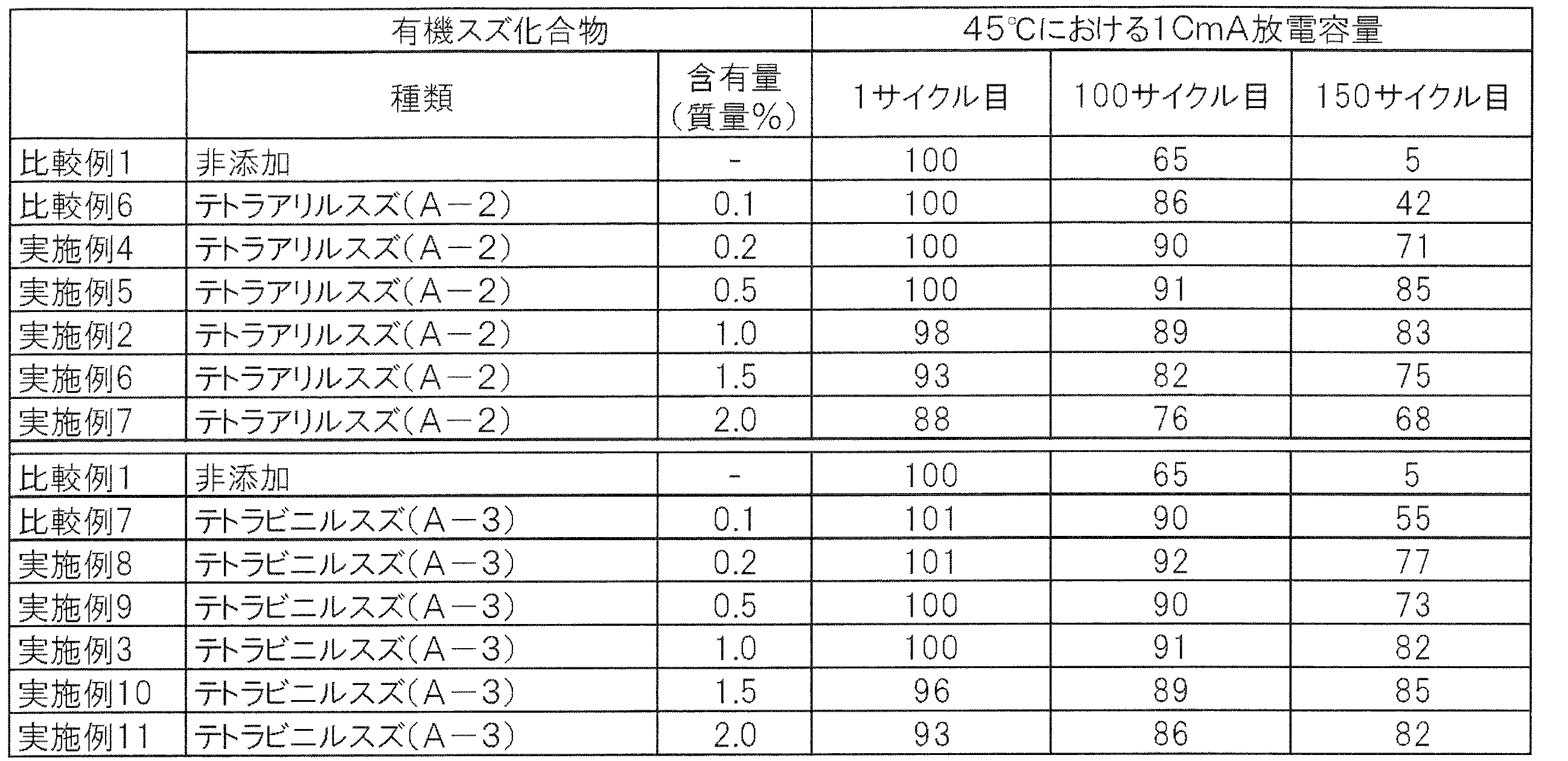
用いた有機スズ化合物の種類及び量を表3に記載のものにしたこと以外は、実施例1と同様にして、実施例4~11及び比較例6~7の非水電解質、及び非水電解質二次電池を得た。なお、表3中には、比較例1、実施例2及び3を再掲している。
用いた有機スズ化合物の種類及び量を表3に記載のものにしたこと以外は、実施例1と同様にして、実施例4~11及び比較例6~7の非水電解質、及び非水電解質二次電池を得た。なお、表3中には、比較例1、実施例2及び3を再掲している。
[実施例12~13]
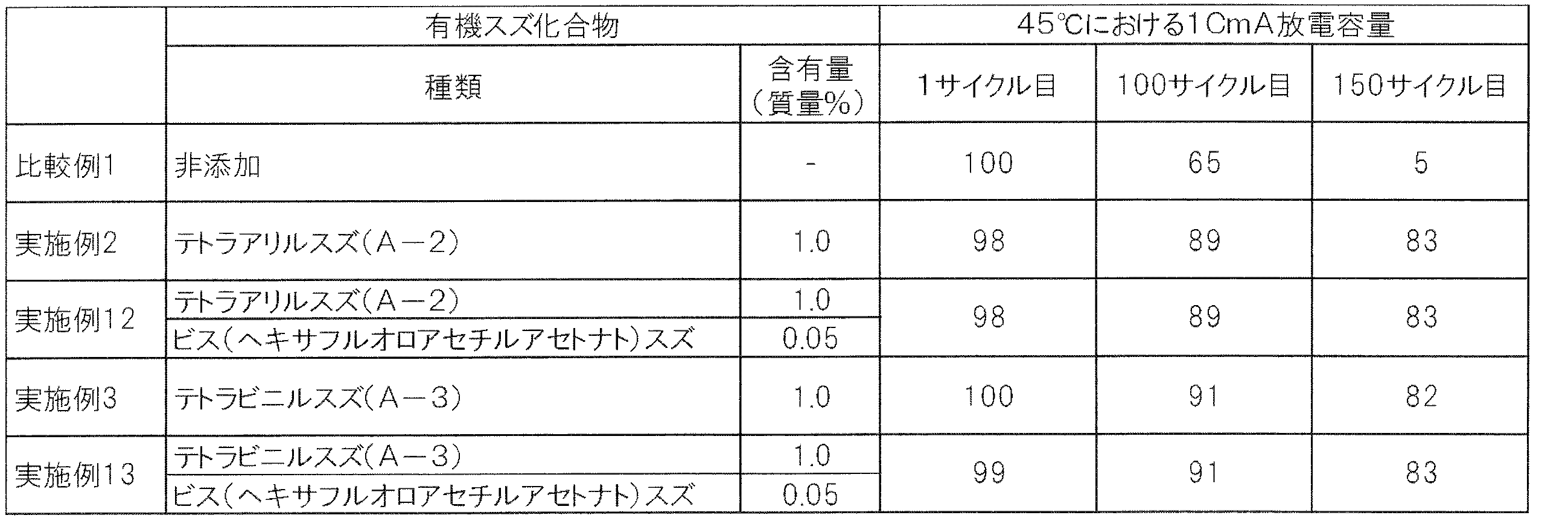
用いた有機スズ化合物の種類及び量を表4に記載のものにしたこと以外は、実施例1と同様にして、実施例12~13の非水電解質、及び非水電解質二次電池を得た。なお、表4中には、比較例1、実施例2及び3を再掲している。
用いた有機スズ化合物の種類及び量を表4に記載のものにしたこと以外は、実施例1と同様にして、実施例12~13の非水電解質、及び非水電解質二次電池を得た。なお、表4中には、比較例1、実施例2及び3を再掲している。
[評価]
比較例1~7及び実施例1~13の非水電解質二次電池について、25℃にて充電電圧4.35V、放電電圧2.75Vとして充放電を行い、初期容量を確認した。次に、45℃にて充放電サイクル試験を行った。具体的には、45℃の環境で、充電電流1C、充電電圧4.35V、充電時間3時間の定電流定電圧充電、及び放電電流1C、放電終止電圧2.75Vの定電流放電を行なう充放電を150サイクル行った。なお、充電と放電の間、及び放電と充電の間に、それぞれ10分の休止期間を設けた。1サイクル目、100サイクル目及び150サイクル目の放電容量を表1、表3及び表4に示す。なお、表中の放電容量は、比較例1の1サイクル目の値を基準とした相対値である。
比較例1~7及び実施例1~13の非水電解質二次電池について、25℃にて充電電圧4.35V、放電電圧2.75Vとして充放電を行い、初期容量を確認した。次に、45℃にて充放電サイクル試験を行った。具体的には、45℃の環境で、充電電流1C、充電電圧4.35V、充電時間3時間の定電流定電圧充電、及び放電電流1C、放電終止電圧2.75Vの定電流放電を行なう充放電を150サイクル行った。なお、充電と放電の間、及び放電と充電の間に、それぞれ10分の休止期間を設けた。1サイクル目、100サイクル目及び150サイクル目の放電容量を表1、表3及び表4に示す。なお、表中の放電容量は、比較例1の1サイクル目の値を基準とした相対値である。
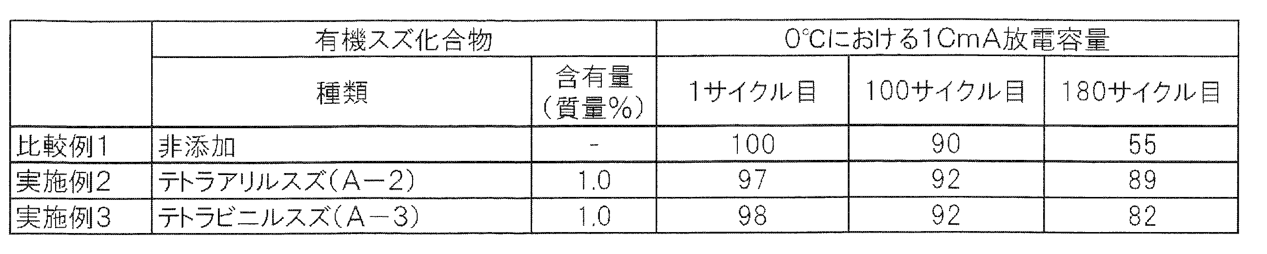
比較例1及び実施例2、3の非水電解質二次電池について、0℃の環境下で行ったこと以外は上記と同様にして充放電サイクル試験を行った。1サイクル目、100サイクル目及び180サイクル目の放電容量を表2に示す。なお、表中の放電容量は、比較例1の1サイクル目の値を基準とした相対値である。

また、別途同様に作製した比較例1~3及び実施例1、2の非水電解質二次電池について、充電電圧4.35V、放電電圧2.75Vとして初期化成を行った後、放電状態で解体した。その後、正極及び負極をDMCで洗浄し、真空乾燥した。その後、正極(正極合材)及び負極(負極合材)のX線光電子吸収分光分析を行った。正極のO1sスペクトルに帰属されるピークにおける、530eV以上534eV以下の範囲のピーク強度(a)、528eV以上530eV未満の範囲のピーク強度(b)、及びこれらの比(a/b)を表5に示す。正極のF1sスペクトルに帰属されるピークにおける、686eV以上689eV以下の範囲のピーク強度(c)、683eV以上686eV未満の範囲のピーク強度(d)、及びこれらの比(c/d)を表6に示す。負極のC1sスペクトルに帰属されるピークにおける、286eV以上288eV以下の範囲のピーク強度(e)、284eV以上286eV未満の範囲のピーク強度(f)、及びこれらの比(e/f)を表7に示す。また、正極合材及び負極合材中のスズの含有量を高周波誘導結合プラズマ発光分光分析法(ICP)によって測定した。測定結果を表8に示す。


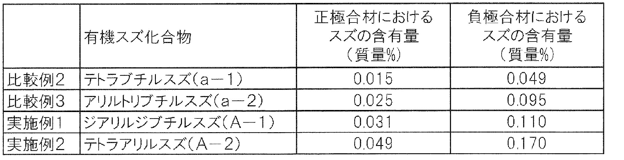
上記表1~4に示されるように、スズ原子と結合し、かつ不飽和結合を有する2つ以上の脂肪族炭化水素基を有する有機スズ化合物を含有し、上記有機スズ化合物の含有量が、0.2質量%以上である非水溶媒を備える各実施例の非水電解質二次電池は、0℃及び45℃のどちらにおいても優れた充放電サイクル寿命を有することがわかる。また、表5~8に示されるように、各実施例の非水電解質二次電池における正極及び負極においては、皮膜の形成量及びスズ含有量が大きいことがわかる。これにより、各実施例の非水電解質二次電池は、広い温度範囲において長い充放電サイクル寿命を有するものと推察される。
また、表4に示されるように、上記式(3)で表される化合物であるビス(ヘキサフルオロアセチルアセトナト)スズを併用しても、テトラアリルスズ等を単独で用いた場合と比較して更なる容量維持率向上効果は奏されなかった。
本発明は、パーソナルコンピュータ、通信端末等の電子機器、自動車などの電源として使用される非水電解質二次電池、及びこれに備わる二次電池用非水電解質などに適用できる。
1 非水電解質二次電池
2 電極体
3 電池容器
4 正極端子
4’ 正極リード
5 負極端子
5’ 負極リード
20 蓄電ユニット
30 蓄電装置
2 電極体
3 電池容器
4 正極端子
4’ 正極リード
5 負極端子
5’ 負極リード
20 蓄電ユニット
30 蓄電装置
Claims (10)
- 非水溶媒に電解質塩が溶解する二次電池用非水電解質であって、
スズ原子と結合し、かつ不飽和結合を有する2つ以上の脂肪族炭化水素基を有する有機スズ化合物を含有し、
上記有機スズ化合物の含有量が、0.2質量%以上であることを特徴とする二次電池用非水電解質。 - 上記有機スズ化合物が、下記式(1)で表される請求項1に記載の二次電池用非水電解質。

- 上記R1が、下記式(2)で表される請求項2に記載の二次電池用非水電解質。

- 上記有機スズ化合物以外の他の有機スズ化合物の含有量が、0.05質量%未満である請求項1、請求項2又は請求項3に記載の二次電池用非水電解質。
- 下記式(3)で表される化合物を含有しない、又は下記式(3)で表される化合物の含有量が0.05質量%未満である請求項1から請求項4のいずれか1項に記載の二次電池用非水電解質。
SnX2 (3)
(式(3)中、Xは、β-ジケトナトである。) - 正極と、負極と、非水電解質とを備える非水電解質二次電池であって、
上記非水電解質として、請求項1から請求項5のいずれか1項に記載の二次電池用非水電解質が用いられていることを特徴とする非水電解質二次電池。 - 正極活物質及びスズを含む正極合材を有する正極と、負極と、非水電解質とを備える非水電解質二次電池であって、
上記正極合材に対するX線光電子吸収分光分析のO1sスペクトルに帰属されるピークにおいて、530eV以上534eV以下の範囲のピーク強度の528eV以上530eV未満の範囲のピーク強度に対する比が1.2以上であることを特徴とする非水電解質二次電池。 - 正極活物質、バインダーとしてのフッ素樹脂及びスズを含む正極合材を有する正極と、負極と、非水電解質とを備える非水電解質二次電池であって、
上記正極合材に対するX線光電子吸収分光分析のF1sスペクトルに帰属されるピークにおいて、686eV以上689eV以下の範囲のピーク強度の683eV以上686eV未満の範囲のピーク強度に対する比が3.0以下であることを特徴とする非水電解質二次電池。 - 負極活物質及びスズを含む負極合材を有する負極と、正極と、非水電解質とを備える非水電解質二次電池であって、
上記負極合材に対するX線光電子吸収分光分析のC1sスペクトルに帰属されるピークにおいて、286eV以上288eV以下の範囲のピーク強度の284eV以上286eV未満の範囲のピーク強度に対する比が0.6以上であることを特徴とする非水電解質二次電池。 - 正極と、負極と、非水電解質とを備える非水電解質二次電池の製造方法であって、
上記非水電解質として、請求項1から請求項5のいずれか1項に記載の二次電池用非水電解質を用いることを特徴とする非水電解質二次電池の製造方法。
Priority Applications (1)
| Application Number | Priority Date | Filing Date | Title |
|---|---|---|---|
| JP2018501013A JP6673460B2 (ja) | 2016-02-26 | 2016-12-20 | 二次電池用非水電解質、非水電解質二次電池、及び非水電解質二次電池の製造方法 |
Applications Claiming Priority (2)
| Application Number | Priority Date | Filing Date | Title |
|---|---|---|---|
| JP2016036410 | 2016-02-26 | ||
| JP2016-036410 | 2016-02-26 |
Publications (1)
| Publication Number | Publication Date |
|---|---|
| WO2017145507A1 true WO2017145507A1 (ja) | 2017-08-31 |
Family
ID=59686023
Family Applications (1)
| Application Number | Title | Priority Date | Filing Date |
|---|---|---|---|
| PCT/JP2016/087941 Ceased WO2017145507A1 (ja) | 2016-02-26 | 2016-12-20 | 二次電池用非水電解質、非水電解質二次電池、及び非水電解質二次電池の製造方法 |
Country Status (2)
| Country | Link |
|---|---|
| JP (1) | JP6673460B2 (ja) |
| WO (1) | WO2017145507A1 (ja) |
Cited By (1)
| Publication number | Priority date | Publication date | Assignee | Title |
|---|---|---|---|---|
| CN109616698A (zh) * | 2018-10-19 | 2019-04-12 | 深圳启辰新能源科技有限公司 | 锂硫电池电解液及其制备方法 |
Citations (3)
| Publication number | Priority date | Publication date | Assignee | Title |
|---|---|---|---|---|
| WO2004100291A1 (ja) * | 2003-05-09 | 2004-11-18 | Sony Corporation | 負極材料およびその製造方法並びに電池 |
| WO2007023700A1 (ja) * | 2005-08-22 | 2007-03-01 | Ube Industries, Ltd. | 非水電解液及びそれを用いたリチウム二次電池 |
| US20150280219A1 (en) * | 2014-03-27 | 2015-10-01 | GM Global Technology Operations LLC | Active electrode materials and methods for making the same |
-
2016
- 2016-12-20 WO PCT/JP2016/087941 patent/WO2017145507A1/ja not_active Ceased
- 2016-12-20 JP JP2018501013A patent/JP6673460B2/ja active Active
Patent Citations (3)
| Publication number | Priority date | Publication date | Assignee | Title |
|---|---|---|---|---|
| WO2004100291A1 (ja) * | 2003-05-09 | 2004-11-18 | Sony Corporation | 負極材料およびその製造方法並びに電池 |
| WO2007023700A1 (ja) * | 2005-08-22 | 2007-03-01 | Ube Industries, Ltd. | 非水電解液及びそれを用いたリチウム二次電池 |
| US20150280219A1 (en) * | 2014-03-27 | 2015-10-01 | GM Global Technology Operations LLC | Active electrode materials and methods for making the same |
Cited By (1)
| Publication number | Priority date | Publication date | Assignee | Title |
|---|---|---|---|---|
| CN109616698A (zh) * | 2018-10-19 | 2019-04-12 | 深圳启辰新能源科技有限公司 | 锂硫电池电解液及其制备方法 |
Also Published As
| Publication number | Publication date |
|---|---|
| JPWO2017145507A1 (ja) | 2018-12-13 |
| JP6673460B2 (ja) | 2020-03-25 |
Similar Documents
| Publication | Publication Date | Title |
|---|---|---|
| CN114447437A (zh) | 用于锂金属电池组的电解质和隔离件 | |
| CN111316494B (zh) | 非水电解质蓄电元件和非水电解质蓄电元件的制造方法 | |
| JP7062975B2 (ja) | 非水電解質及び非水電解質蓄電素子 | |
| JP6652072B2 (ja) | 非水電解質、蓄電素子及び蓄電素子の製造方法 | |
| JP2018181772A (ja) | 非水電解質蓄電素子及びその製造方法 | |
| JP2018067501A (ja) | 非水電解質蓄電素子 | |
| JP7076067B2 (ja) | 非水電解質二次電池、及び非水電解質二次電池の製造方法 | |
| KR101897331B1 (ko) | 비수 전해액 이차 전지 | |
| JP2017208215A (ja) | 蓄電素子用非水電解質、非水電解質蓄電素子及びその製造方法 | |
| JP2021077608A (ja) | 非水電解質、非水電解質蓄電素子及び非水電解質蓄電素子の製造方法 | |
| JP7137757B2 (ja) | 非水電解質蓄電素子 | |
| JP6911655B2 (ja) | 蓄電素子用非水電解質、非水電解質蓄電素子、及び非水電解質蓄電素子の製造方法 | |
| JP6747312B2 (ja) | 非水電解質、蓄電素子及び蓄電素子の製造方法 | |
| JP7363792B2 (ja) | 非水電解質蓄電素子及び非水電解質蓄電素子の製造方法 | |
| JP7155719B2 (ja) | 非水電解質蓄電素子及び非水電解質蓄電素子の製造方法 | |
| JP6919202B2 (ja) | 非水電解質、蓄電素子及び蓄電素子の製造方法 | |
| JP6673460B2 (ja) | 二次電池用非水電解質、非水電解質二次電池、及び非水電解質二次電池の製造方法 | |
| JP2019087350A (ja) | 蓄電素子及び蓄電素子の製造方法 | |
| JP6922242B2 (ja) | 非水電解質蓄電素子及び非水電解質蓄電素子の製造方法 | |
| JP2020173998A (ja) | 非水電解質蓄電素子及び非水電解質蓄電素子の製造方法 | |
| JP6819326B2 (ja) | 非水電解質蓄電素子及びその製造方法 | |
| JP7159864B2 (ja) | 非水電解質蓄電素子及びその使用方法 | |
| JP2017204393A (ja) | 二次電池用非水電解質、非水電解質二次電池、及び非水電解質二次電池の製造方法 | |
| JP2018106895A (ja) | 正極活物質、正極、及び非水電解質蓄電素子 |
Legal Events
| Date | Code | Title | Description |
|---|---|---|---|
| ENP | Entry into the national phase |
Ref document number: 2018501013 Country of ref document: JP Kind code of ref document: A |
|
| NENP | Non-entry into the national phase |
Ref country code: DE |
|
| 121 | Ep: the epo has been informed by wipo that ep was designated in this application |
Ref document number: 16891662 Country of ref document: EP Kind code of ref document: A1 |
|
| 122 | Ep: pct application non-entry in european phase |
Ref document number: 16891662 Country of ref document: EP Kind code of ref document: A1 |