WO2017145504A1 - 現金処理機、端末装置、及び現金処理システム - Google Patents
現金処理機、端末装置、及び現金処理システム Download PDFInfo
- Publication number
- WO2017145504A1 WO2017145504A1 PCT/JP2016/087672 JP2016087672W WO2017145504A1 WO 2017145504 A1 WO2017145504 A1 WO 2017145504A1 JP 2016087672 W JP2016087672 W JP 2016087672W WO 2017145504 A1 WO2017145504 A1 WO 2017145504A1
- Authority
- WO
- WIPO (PCT)
- Prior art keywords
- password
- cash
- processing
- authentication
- unit
- Prior art date
- Legal status (The legal status is an assumption and is not a legal conclusion. Google has not performed a legal analysis and makes no representation as to the accuracy of the status listed.)
- Ceased
Links
Images








Classifications
-
- G—PHYSICS
- G07—CHECKING-DEVICES
- G07D—HANDLING OF COINS OR VALUABLE PAPERS, e.g. TESTING, SORTING BY DENOMINATIONS, COUNTING, DISPENSING, CHANGING OR DEPOSITING
- G07D9/00—Counting coins; Handling of coins not provided for in the other groups of this subclass
Definitions
- the present disclosure relates to a cash processing machine, a terminal device, and a cash processing system, and can be applied to security management of a cash processing machine installed in a financial institution such as a bank.
- a cash processing machine represented by a cash machine for a counter installed at a counter of a financial institution is used for depositing / withdrawing transactions of banknotes and coins, and counting and counting.
- the operator can perform transactions such as deposit / withdrawal by performing various operations from the operation unit of the cash processing machine or the reception terminal (information processing apparatus) connected to the cash processing machine.
- Patent Document 1 describes setting a password and an authority level for each operator on a POS terminal of a POS (point of sales) system used in a supermarket or the like.
- a cash processor a terminal device (a terminal device that accepts processing executed by the cash processor), and a cash processing system that can easily improve security are desired.
- 1st aspect of this indication is a cash processing machine which processes cash, Comprising: (1) Password holding
- a second aspect of the present disclosure is a terminal device that accepts a process instructing a cash processor that processes cash, (1) a process reception unit that receives an input of a process to be executed by the cash processor; (2) a password receiving unit that receives a password of the number of digits corresponding to the processing authority level of the process received by the processing receiving unit; and (3) authentication using the password received by the password receiving unit.
- a third aspect of the present disclosure is a cash processing system including a cash processing machine that processes cash and a terminal device that receives a process instructing the cash processing machine.
- a cash processing machine is applied, and the terminal device according to the second aspect is applied as the terminal device.
- FIG. 1 is a block diagram showing the overall configuration of the cash processing system 1000 of this embodiment.
- FIG. 2 is a schematic cross-sectional view of the cash processor 10.
- one cash processing machine 10 and one terminal device 20 are arranged in the cash processing system 1000 shown in FIG. 1, but the number of arrangement of each device is not limited.
- a plurality of terminal devices 20 may be connected to one cash processing system 1000.
- the cash processor 10 and the terminal device 20 are connected by an interface 30.
- the configuration of the interface 30 is not limited, for example, a LAN interface (a network configured by a LAN cable, a switch, a router, or the like), a USB interface (for example, a USB cable), or the like can be applied.
- the cash processing system 1000 is a system used for cash management at a financial institution or the like.
- the cash processing machine 10 is a device that executes cash withdrawal and deposit based on operations by an operator such as a reception counter of a financial institution. Although it is possible to directly operate the cash processing machine 10 itself, the reception counter member of the financial institution mainly operates the cash processing machine 10 via the terminal device 20.
- the cash processing machine 10 includes a control unit 11, a storage unit 12, a cash processing unit 13, and an operation display unit 14.
- the operation display unit 14 functions as an interface (user interface) for outputting information to the operator and receiving operations from the operator.
- a specific device configuration applied to the operation display unit 14 is not limited, for example, various devices such as a touch panel display can be used.
- the operation display unit 14 displays an operation screen (GUI screen) using a touch panel display or the like (for example, displays a menu screen or a processing result screen), and outputs information to the operator and accepts operation from the operator.
- GUI screen operation screen
- the operation display unit 14 may further include hardware buttons, switches, levers, and the like (not shown).
- the cash processing unit 13 is a device that performs a deposit process for cash input from an operator, a withdrawal process for stored cash, and the like.
- the control unit 11 has a function of controlling the cash processing machine 10 as a whole.
- the control unit 11 controls processing such as deposit, withdrawal, collection, and organizing counting. Further, the control unit 11 controls the cash processing machine 10 as a whole so as to execute processing (operation) instructed by the operator from the operation display unit 14 or processing instructed by the operator from the terminal device 20.
- the storage unit 12 is a storage unit that stores data used in processing of the control unit 11 and the like.
- the storage unit 12 stores password data 121 used for authentication processing.
- the control unit 11 and the storage unit 12 may be realized by, for example, a processor, a ROM (Read Only Memory), a RAM (Random Access Memory), and the like, and by installing the control program according to the embodiment on a computer having them. It may be realized.
- FIG. 2 is a schematic sectional view of the cash processor 10. In FIG. 2, the cash processing unit 13 and the operation display unit 14 are illustrated.
- the cash processing unit 13 includes a deposit port 1 for inserting banknotes, a withdrawal port 2 for discharging banknotes, a temporary storage unit 3, a banknote recognition unit 4, a transport unit 5, banknote cassettes 6A to 6D, and a banknote cassette 7.
- the banknote cassette 7 has a banknote storage 8 and a reject storage 9.
- the deposit port 1 is a slot into which an operator inserts banknotes.
- the deposit port 1 is provided with a shutter (not shown) that opens and closes the opening. Further, the deposit port 1 has a separation function of separating and feeding out banknotes inserted in a bundle one by one.
- the withdrawal port 2 is a discharge port through which banknotes received by the operator are discharged.
- the withdrawal port 2 is provided with a shutter (not shown) that opens and closes the opening. Further, the withdrawal port 2 has a stacking function for stacking banknotes to be discharged.
- the deposit port 1 has a separation function of feeding out inserted banknotes one by one.
- the withdrawal port 2 has a stacking function for stacking banknotes to be discharged as described above.
- the temporary storage unit 3 has both functions of separating and accumulating banknotes.
- the temporary holding unit 3 temporarily accumulates the banknotes separated from the deposit port 1 and identified as normal by the banknote recognition unit 4 during the deposit transaction.
- the banknotes accumulated in the temporary storage unit 3 are paid out when a transaction is established, for example, when the account of the deposited banknote is confirmed, and is conveyed to the banknote cassettes 6A to 6D through the banknote recognition unit 4.
- the bill recognition unit 4 performs discrimination of bills passing one by one.
- the traveling direction of the banknotes corresponds to both directions, and the banknote recognition unit 4 can discriminate between banknotes transported from the deposit port 1 direction and banknotes transported from the opposite direction.
- the transport unit 5 includes each transport path that transports banknotes, each transport roller, and a drive mechanism that drives each transport path.
- the drive mechanism drives the conveyance path by rotating, for example, a DC servo motor or a pulse motor.
- the conveyance part 5 is controlled by the control part 11, and conveys a banknote to the target conveyance destination.
- the banknote cassettes 6A to 6D are banknote storage units that can store banknotes for each denomination, and have both functions of stacking and separating banknotes.
- the banknote cassettes 6A to 6D may include a plurality of banknote cassettes for the same denomination.
- the banknote cassettes 6A to 6D have a structure that can be attached to and detached from the cash processing machine 10, and the banknote cassettes 6A to 6D can be loaded with banknotes by exchanging them individually.
- the banknote cassette 7 includes a banknote storage 8 on the upper side and a reject storage 9 on the lower side (bottom). Moreover, the banknote cassette 7 becomes a structure which can be attached or detached with respect to the cash processing machine 10, and collection
- the banknote storage 8 has a stacking function for stacking banknotes and a separating function for feeding one by one.
- the banknote storage 8 can collect banknotes separated from the banknote cassettes 6A to 6D at the time of cassette count collection and collect banknotes. Moreover, the banknote storage 8 can feed out the banknotes accommodated in the cassette count replenishment and replenish the banknote cassette 6 with the banknotes.
- the reject box 9 has only a stacking function for stacking banknotes.
- the reject store 9 is a banknote storage unit for stacking banknotes (reject banknotes) that have been identified as abnormal (rejection determination) by the banknote recognition unit 4.
- the terminal device 20 is a device configured by installing the terminal program according to the embodiment in a computer such as a PC.
- the functional configuration of the terminal device 20 can be illustrated as shown in FIG. 1, for example.
- the terminal device 20 includes a control unit 21, a storage unit 22, and an operation display unit 23.
- the control unit 21 has a control function of the terminal device 20 as a whole, a communication function with the cash processor 10, and the like.
- the storage unit 22 is a storage unit that stores data used in the processing of the control unit 21 and the like.
- the control unit 21 and the storage unit 22 may be realized using, for example, a computer having a processor (for example, a CPU) and a memory.
- the operation display unit 23 functions as an interface (user interface) for outputting information to the operator and receiving operations from the operator.
- a specific device configuration applied to the operation display unit 23 is not limited, for example, a configuration in which various devices such as a display, a keyboard, and a mouse (not shown) may be combined.
- the operation display unit 23 displays an operation screen (GUI screen) to the operator (for example, displays a menu screen or a processing result screen), and can output information to the operator and accept operations from the operator. It demonstrates as what is comprised.
- control unit 21 a program operating on the control unit 21
- control unit 21 has three programs installed, that is, an application 211, a control driver 212, and a communication driver 213.
- the communication driver 213 is a driver for communicating with the cash processing machine 10 via the interface 30.
- the control driver 212 is a driver for communicating with the cash processing machine 10 using the communication driver 213 and controlling the cash processing machine 10 (for example, control by sending various commands).
- the control driver 212 performs control (for example, command transmission) with respect to the cash processing machine 10 according to an instruction from the application 211.
- the application 211 is responsible for receiving operations from the user and outputting information to the user using the operation display unit 23.
- the application 211 performs a process of displaying an operation screen (GUI screen) on the operation display unit 23 and receiving an input from the user (for example, an input using a mouse or a keyboard).
- the application 211 causes the cash processing machine 10 to execute various processes (for example, a deposit process, a withdrawal process, various setting change processes, etc.) via the control driver 212 in accordance with an operation on the operation screen by the user.
- various processes for example, a deposit process, a withdrawal process, various setting change processes, etc.
- the password data 121 is cash as authentication information when the cash processing machine 10 accepts a process execution operation (including an indirect operation using the terminal device 20) from the operator. It is stored in the storage unit 12 of the processor 10.
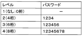
- FIG. 3 is an explanatory diagram showing a configuration example of the password data 121 in a table format.
- the password data 121 is data in which a password for each operation authority level (hereinafter referred to as “processing authority level”) is defined.
- FIG. 4 is an explanatory diagram showing the structure of authority and password for each processing authority level.
- four levels of operation authority 1 to 4 are set for the cash processing machine 10, and the wider (higher) operation authority as the number of processing authority levels increases. Is set.
- a minimum required operation authority level is set for each operation.
- the cash processing machine 10 performs authentication using a password when receiving an operation, and the range of operations that can be accepted (input) differs according to the processing authority level corresponding to the authenticated password. For example, when authentication is performed with a password of processing authority level 3, the cash processing machine 10 (control unit 11) can only accept processes with a processing authority level of 3 or lower, and accept operations with a processing authority level of 4 or higher. Can not.
- authentication is performed only with a password, and a user ID or the like for each operator or each processing authority level is not defined.
- an ID may be assigned for each operator or each processing authority level, and authentication may be performed by checking a combination of ID and password.
- the number of password digits for each processing authority level is not limited to the example in FIG. 3 and may be an arbitrary combination. Moreover, in the cash processing machine 10, you may make it changeable the number of password digits of each process authority level by operation of an operator.
- processing authority level 1 is used by a general bank employee in a bank (financial institution).
- Processing at processing authority level 1 includes, for example, general transactions such as deposits and withdrawals (transactions performed by bank employees in daily work).
- the processing authority level 2 is used by a manager class employee in a bank (financial institution).
- the processing authority level 2 processing includes, for example, setting change processing related to the operation of the cash processing machine 10 (for example, change of the cassette configuration, etc.).
- processing authority level 3 is used by maintenance personnel of the cash processor 10.
- processing of processing authority level 3 for example, setting change processing relating to security of the cash processing machine 10 (for example, a maintenance person performs operations such as changing the recognition rate of banknotes).
- the processing authority level 4 processing includes, for example, all password clearing (initialization) of processing authority levels 1 to 3.
- the storage unit 12 functions as a password holding unit that holds a password (password data 121). Moreover, in the cash processing machine 10, when the control part 11 performs a process, it functions as an authentication part which performs the authentication process using the password of the process authority level corresponding to the said process. Furthermore, in the cash processing machine 10, the control unit 11 functions as a process execution unit that executes a process that has been successfully authenticated.
- the application 211 of the control unit 21 functions as a process reception unit that receives an input of a process to be executed by the cash processing machine 10. Further, in the terminal device 20, the application 211 of the control unit 21 functions as a password receiving unit that receives a password having the number of digits corresponding to the processing authority level of the processing received via the operation display unit 23. Further, in the terminal device 20, the application 211 of the control unit 21 functions as a process execution instruction unit that instructs the cash processing machine 10 to execute a process received when authentication is successful.
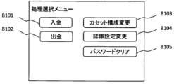
- the application 211 is not limited in the configuration of a screen that accepts a process selection to be executed from an operator, for example, a menu screen as shown in FIG. 6 (hereinafter referred to as a “process selection menu screen”) may be used. .
- a menu screen as shown in FIG. 6 hereinafter referred to as a “process selection menu screen”
- buttons B101 to B106 for receiving selection for each process are arranged.
- a button B101 for selecting a deposit transaction process at a processing authority level 1 a button B102 for selecting a withdrawal transaction process at a process authority level 1, and a cassette configuration at a process authority level 2
- a button B103 for selecting change processing a button B104 for selecting recognition setting change processing for processing authority level 3
- a button B105 for selecting password clear processing for processing authority level 4 are arranged.
- the process selection menu screen of FIG. 6 has a configuration in which buttons for accepting processes of processing authority levels 1 to 4 for simplifying the description are arranged on one menu screen.
- the menu screen that accepts the process selection from the operator may have a structure suitable for the number of processes that can be selected, such as a configuration in which a plurality of screens are hierarchized.
- the application 211 of the terminal device 20 confirms the processing authority level of the selected process (S102).
- the processing authority level information of each process may be registered in the application 211 in advance, and the application 211 may check the processing authority level of the process selected by the operator with reference to the information.
- processing selected by the operator is processing at processing authority level 1, no password input is required (the password is 0 digits), and therefore the application 211 does not request password input, but will be described later in step S110. Transition to processing.
- the application 211 causes the operation display unit 23 to display a password input screen for accepting a 4-digit password input corresponding to the process authority level 2 (S103). ).
- the application 211 causes the operation display unit 23 to display a password input screen for accepting a 6-digit password input corresponding to the process authority level 3 (S104). ).
- the application 211 causes the operation display unit 23 to display a password input screen for accepting an 8-digit password input corresponding to the process authority level 4 ( S105).
- the application 211 accepts the password input on the password input screen displayed in any of steps S103 to S104 (S106).
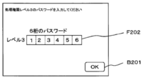
- 7A to 7C are explanatory diagrams showing an example of the configuration of the password input screen.
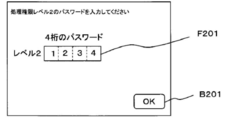
- FIG. 7A is a configuration example of a password input screen for accepting a 4-digit password input.
- a field F201 for accepting a 4-digit password entry and an OK button B201 for accepting completion of password entry are arranged.
- FIG. 7B is a configuration example of a password entry screen for accepting a 6-digit password entry.
- a field F202 for accepting a 6-digit password entry and an OK button B201 for accepting completion of password entry are arranged.
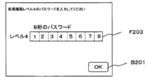
- FIG. 7C is a configuration example of a password input screen for accepting an 8-digit password input.
- a field F203 for accepting an 8-digit password entry and an OK button B201 for accepting completion of the password entry are arranged.
- the application 211 When the application 211 displays the password input screen, the application 211 performs a process of accepting a password input with the number of digits corresponding to the displayed password input screen.
- 7A to 7C are configured to display the entered numbers in the field for accepting the password input, but display the masked entered numbers (for example, enter the entered numbers as “* It may be replaced with a symbol such as “
- the application 211 checks whether or not the number of digits of the input password matches the number of digits requested to be input on the displayed password input screen (S107). If the input password does not match the number of digits requested to be input, the application 211 returns to any of the above-described steps S103 to S105 and starts again from the process of displaying the password input screen having the same number of digits.
- the application 211 transmits an authentication request to the control unit 11 of the cash processing machine 10 via the control driver 212 and the communication driver 213 (S108). At this time, the application 211 notifies the cash processing machine 10 (control unit 11) of the input password and the processing authority level for requesting authentication. And the control part 11 of the cash processing machine 10 will collate the notified password and the password registered into the password data 121, and will perform authentication OK or authentication NG with the terminal device 20 (application). 211).
- step S110 the application 211 receives an input of the detailed content of the process selected in step S101 described above and transmits a command (command) for requesting the cash processing machine 10 to execute the process.
- the cash processing machine 10 control unit 11 also checks whether or not the authentication of the processing authority level corresponding to the process is successful every time the process is executed, If the processing authority level of the processing does not match the processing authority level that has been successfully authenticated immediately before, the processing execution request from the terminal device 20 may be rejected.
- the cash processing machine 10 can execute processing according to the processing authority level of the operator.
- the application 211 When the password change process is selected, the application 211 further displays on the operation display unit 23 an operation screen (hereinafter referred to as a “processing authority level selection screen”) that accepts selection of a processing authority level for changing the password.
- the processing authority level is accepted from the operator (S202).
- processing authority level selection screen is not limited, for example, an operation screen as shown in FIG. 10 may be used.
- buttons B301 to B303 for accepting selection of the processing authority level are arranged.
- a button B301 for selecting processing authority level 2 a button B302 for selecting processing authority level 3, and a button B303 for selecting processing authority level 4 are arranged. Yes.
- the application 211 of the terminal device 20 confirms the selected processing authority level (S203).
- the application 211 displays a password input screen (operation screen of FIG. 7A) for accepting a 4-digit password input corresponding to the processing authority level 2 on the operation display unit 23. It is displayed (S204).
- the application 211 displays a password input screen (operation screen of FIG. 7B) for accepting a 6-digit password input corresponding to the processing authority level 3 as an operation display unit. 23 is displayed (S205).
- the application 211 operates a password input screen (operation screen in FIG. 7C) for accepting an 8-digit password input corresponding to the process authority level 4. It is displayed on the display unit 23 (S206).
- the application 211 receives a password input on the password input screen displayed in any of steps S204 to S206 (S207).
- the application 211 confirms whether or not the number of digits of the input password matches the number of digits requested to be input on the displayed password input screen (S208). If the input password does not match the number of digits requested to be input, the application 211 returns to any of the above-described steps S204 to S206 and starts the process of displaying the password input screen having the same number of digits again.
- the application 211 transmits a verification request (authentication request) to the control unit 11 of the cash processing machine 10 via the control driver 212 and the communication driver 213. (S209). And the control part 11 of the cash processing machine 10 will collate the notified password and the password registered in the password data 121, and will perform collation OK or collation NG with the terminal device 20 (application 211).
- the application 211 confirms the reply from the cash processing machine 10 (control part 11) (S210), and when the reply from the cash processing machine 10 (control part 11) is collation OK, it is step S211 mentioned later.
- the process proceeds to the verification NG, the process returns to any of the above-described steps S204 to S206 to start again from the process of displaying the password input screen having the same number of digits.
- the application 211 confirms the processing authority level in which the collation result is OK (S211).
- the application 211 causes the operation display unit 23 to display a password change screen for accepting an input of a password (4-digit password) after changing the processing authority level 2 ( S212).
- the application 211 operates the password change screen for accepting the input of the changed processing authority levels 2 and 3 (4-digit and 6-digit passwords). It is displayed on the display unit 23 (S213).
- the application 211 accepts the input of the password (4-digit, 6-digit, and 8-digit password) after changing the processing authority levels 2, 3, and 4.
- the password change screen is displayed on the operation display unit 23 (S214).
- the application 211 receives the changed password input on the password change screen displayed in any of steps S212 to S214 (S215).
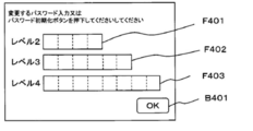
- 11A to 11C are explanatory diagrams showing an example of the configuration of the password change screen.
- FIG. 11A is a configuration example of a password change screen for accepting a password of processing authority level 2 (four digits).
- a field F401 for accepting a 4-digit password entry and an OK button B401 for accepting completion of password entry are arranged.
- FIG. 11B is a configuration example of a password change screen for accepting a password entry of processing authority level 2 (4 digits) and processing authority level 4 (6 digits).
- a field F401 for accepting a 4-digit password entry a field F402 for accepting a 6-digit password entry, and an OK button B401 for accepting completion of password entry are arranged.
- FIG. 11C is a configuration example of a password change screen for accepting password inputs of processing authority level 2 (4 digits), processing authority level 4 (6 digits), and processing authority level 4 (8 digits).
- a field F401 for accepting a 4-digit password entry a field F402 for accepting a 6-digit password entry, a field F403 for accepting an 8-digit password entry, and OK for accepting completion of the password entry.
- Button B401 is arranged.
- the application 211 When the application 211 displays the password change screen, the application 211 performs a process of accepting password input of the number of digits corresponding to the displayed password change screen.
- a plurality of levels of password input may be accepted at the same time.
- 11A to 11C are configured to display entered numbers in the field for accepting password input, but display the masked entered numbers (for example, enter * It may be displayed in place of symbols such as “
- the application 211 confirms whether or not the number of digits of the input password matches the number of digits requested for input for each field (S216). If the password entered on the password change screen does not match the number of digits requested to be input, the application 211 returns to any of the above steps S212 to S214 to display the password change screen with the same processing authority level again. Operate.
- the application 211 receives a password change request (input to the control unit 11 of the cash processing machine 10 via the control driver 212 and the communication driver 213). Command) is transmitted (S217).
- the cash processing machine 10 control unit 11
- the cash processing machine 10 changes the password of the notified processing authority level (changes the content of the password data 121).
- the password data 121 (password for each processing authority level) registered in the cash processing machine 10 can be changed.
- the cash processing system 1000 is configured to be able to change only the password below the processing authority level of the operator.
- the operator can execute only processing according to his authority. Thereby, in the cash processing system 1000, even if some passwords (for example, passwords of processing authority levels 2 and 3) are leaked, not all processing of the cash processing machine 10 can be executed illegally. Security can be improved.
- a higher processing authority level can set a password with a larger number of digits, and a higher processing authority level can ensure higher security. For example, if a 4-digit password can be set uniformly for all processing authority levels, the password entered by an operator who has only a low processing authority (an operator who only knows a password with a low processing authority level) It is possible to prevent accidental execution of processing that coincides with a password having a higher processing authority level by accident.
- FIGS. 5 to 10 described above an example in which processing is executed in accordance with an instruction (command) from the terminal device 20 has been described.
- the operation display unit 14 of the cash processing machine 10 itself, the same as in FIGS. 5 to 10 described above.
- An operation screen may be displayed to accept a process execution instruction from the operator.
- the control unit 11 of the cash processing machine performs password authentication processing using the processing authority level with reference to the password data 121 in the own device.
- the security is improved in the same manner as in the case where the terminal device 20 receives the instruction. There is an effect.
- FIG. 12 is a block diagram showing a configuration of a cash processing system 1000A according to the second embodiment.
- FIG. 12 the same or corresponding parts as those in FIG. Hereinafter, only the difference between the second embodiment and the first embodiment will be described.
- the second embodiment is different from the first embodiment in that the cash processing machine 10 and the terminal device 20 are replaced with the cash processing machine 10A and the terminal device 20A, respectively.
- password mode setting information 211A for setting whether or not to enable the password mode (password authentication using the processing authority level) in the cash processing machine 10A is set in the application 211. This is different from the first embodiment in that it is registered (held).
- the password mode setting information 211A is flag information in which either a value that enables the password mode in the cash processing machine 10A or a value that disables the password mode in the cash processing machine 10A is set.
- the first embodiment is that the password mode setting information 122 in the same format as the password mode setting information 211A is registered (held) in the storage unit 12. Is different.
- the control unit 11 of the cash processing machine 10A is activated for the first time (for example, activated in a factory-shipped state or a state initialized to a factory-shipped state)
- the control unit 11 accesses the terminal device 20A and sets a password mode.
- the value of the information 211A is acquired, and processing for reflecting the password mode setting information 122 in the storage unit 12 is performed.
- the storage unit 12 functions as a set value holding unit that holds the password mode setting information 122.
- the application 211 of the control unit 21 functions as a setting value holding unit that holds the password mode setting information 211A.
- FIG. 13 is a flowchart showing an operation when the cash processor 10A (control unit 11) is activated for the first time.
- the initial setting value (setting value before the first time starting) of password mode setting information 122 shall be a value which invalidates password mode.
- control unit 11 of the cash processing machine 10A When the control unit 11 of the cash processing machine 10A is activated for the first time, it accesses the terminal device 20A (application 211) to request and read the setting value of the password mode setting information 211A set on the terminal device 20A side ( S301).
- the control unit 11 checks the setting value of the acquired password mode setting information 211A (S302), and only when the acquired setting value is a value that enables the password mode, the password mode on the own device side.
- the setting information 122 is changed (changed to a value that enables the password mode) (S303).
- the control unit 11 may transmit a notification that the password mode has been effectively changed in the own device to the terminal device 20A side.
- the cash machine 10 operates in a state where the password mode is enabled.
- control unit 11 turns off the power of its own device (or shuts down without powering off) (S304), and terminates the operation at the first activation. If the password mode is set to be valid in step S303 described above, the cash processing machine 10 (the control unit 11) is activated with the password mode validated after the next activation.
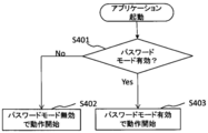
- the application 211 of the terminal device 20A When the application 211 of the terminal device 20A is activated, it confirms the content of the password mode setting information 211A (S401).
- the application 211 thereafter operates with the password mode disabled (S402). In this case, the application 211 executes the process in which the operation is accepted from the operator without executing authentication using a password (regardless of the processing authority level).
- the application 211 thereafter operates with the password mode enabled (S403). In this case, the application 211 executes the process that accepted the operation from the operator after performing authentication with a password using the process authority level (executes the same process as in the first embodiment).
- the application 211 when the cash processing machine 10A is activated, the application 211 sends the setting value of the password mode setting information 122 (a value indicating that the password mode is enabled or disabled) to the cash processing machine 10A. Notification (command transmission).
- the opportunity for the application 211 to notify the cash processing machine 10A of the setting value of the password mode setting information 122 is not limited.
- the application 211 monitors the state of the cash processing machine 10A via the interface 30, and notifies the setting value of the password mode setting information 122 when detecting that the cash processing machine 10A is activated (powered on). (Command transmission) may be performed, or the setting value of the password mode setting information 122 may be notified (command transmission) in response to a request from the cash processing machine 10A.
- the cash processing machine 10A (control unit 11) is activated after the second time (after the process of the flowchart of FIG. 13), first, the password mode setting information 122 set in the own device is referred to and the password mode is valid. It is confirmed whether it is invalid or invalid (S501).
- the control unit 21 thereafter operates in a state where the password mode is disabled (S506). In this case, when executing the process received from the operation display unit 14 or the terminal device 20A, the control unit 21 executes without executing authentication using a password (executed regardless of the processing authority level).
- the control unit 21 sets the password mode setting value (setting of the password mode setting information 211A) from the terminal device 20A (application 211). Value) command is received (S502), and the set value of the command is confirmed (S503).
- the trigger for the control unit 21 to receive the command for the password mode setting value from the terminal device 20A is not limited.
- the control unit 21 cannot execute the process in the terminal device 20A (application 211) with an error (password mode invalid). Error) (S504), and the operation returns to step S502. That is, when the password mode is set to be valid on the cash processing machine 10A side (password mode setting information 122), the control unit 21 rejects the execution of the process unless the password mode is also valid on the terminal device 20A side ( All commands will be rejected). At this time, even if the cash processing machine 10A accepts an operation directly from the operation display unit 14, the execution of the process is rejected.
- the control unit 21 when the command received from the terminal device 20A (the application 211) has the content that validates the password mode, the control unit 21 thereafter starts the operation with the password mode validated (S505). In this case, the control unit 21 executes the process that accepted the operation from the operator after performing authentication with a password using the process authority level (executes the same process as in the first embodiment).
- the password mode setting information 122 of the cash processing machine 10A is set to a value that enables the password mode, an operation (processing execution) by an unauthorized person is prevented. be able to.
- the application of the terminal device is configured to be able to operate all processing authority levels.
- the application program
- security can be further increased. It becomes possible to improve.
Landscapes
- Physics & Mathematics (AREA)
- General Physics & Mathematics (AREA)
- Financial Or Insurance-Related Operations Such As Payment And Settlement (AREA)
Abstract
処理を実行する際の処理権限のレベルごとに異なる桁数のパスワードを保持するパスワード保持部と、指示された処理を実行する際に、前記処理に対応する処理権限レベルのパスワードを用いた認証処理を行うよう構成された認証部と、前記認証部で認証が成功した処理を実行するよう構成された処理実行部と、を有する、現金処理機を提供する。
Description
本願は、2016年2月24日出願の日本国出願、特願2016-033251号の優先権を主張すると共に、その全体が参照により本明細書に取り込まれる。
本開示は、現金処理機、端末装置、及び現金処理システムに関し、例えば、銀行などの金融機関に設置される現金処理機のセキュリティ管理に適用し得る。
本開示は、現金処理機、端末装置、及び現金処理システムに関し、例えば、銀行などの金融機関に設置される現金処理機のセキュリティ管理に適用し得る。
昨今、金融機関の営業店カウンタに設置される窓口用現金処理機に代表される現金処理機は、紙幣や硬貨の入金/出金取引、および整理計数等に利用される。オペレータは、この現金処理機の操作部または、現金処理機に接続された受付端末(情報処理装置)から各種操作を行なうことにより、入金/出金などの取引を行うことができる。
従来、現金処理機では、種々の現金処理の取引や設定変更等を受付ける際に、パスワードの入力を要求することが可能となっている。そして、従来、金融機関等に設置される現金処理機では、パスワード管理を行う場合、一律のパスワードを定義するか、オペレータ毎に同一桁数で異なるパスワードを定義していた。
従来の取引処理を行う装置上でパスワード管理可能な技術としては特開平8-16926号公報に記載の技術がある。特許文献1には、スーパーマーケット等で用いられるPOS(point of sales)システムのPOS端末上で、オペレータごとにパスワードと権限レベルを設定することについて記載されている。
しかしながら、従来の現金処理機では、仮に特開平8-16926号公報に記載されたPOSシステムのように、一律のパスワードを定義していた場合、パスワードが漏洩すると全機能の処理が実行可能となってしまう恐れがあった。
また、オペレータ毎に異なるパスワードを設定していた場合は、オペレータの人数が増加するとデータ量が増加し管理が複雑になり、処理時間がかかってしまう。また、個人毎ではなく、権限毎にセキュリティを定義したい場合は、個人毎のパスワード管理には、管理効率上の無駄がある。
以上のような問題に鑑みて、容易にセキュリティ性を向上させることができる現金処理機、端末装置(現金処理機に実行させる処理を受付ける端末装置)、及び現金処理システムが望まれている。
本開示の第1の態様は、現金を処理する現金処理機であって、(1)当該現金処理機で処理を実行する際の処理権限のレベルごとに異なる桁数のパスワードを保持するパスワード保持部と、(2)指示された処理を実行する際に、当該処理に対応する処理権限レベルのパスワードを用いた認証処理を行う認証部と、(3)前記認証部で認証が成功した処理を実行する処理実行部とを有する。
本開示の第2の態様は、現金を処理する現金処理機に指示する処理を受付ける端末装置であって、(1)前記現金処理機に対して実行させる処理の入力を受ける処理受付部と、(2)前記処理受付部で受付けた処理の処理権限レベルに対応する桁数のパスワード入力を受けるパスワード受付部と、(3)前記パスワード受付部が入力を受けたパスワードを用いた認証を前記現金処理機に要求する認証要求部と、(4)前記認証要求部で要求した認証が成功した場合に、前記処理受付部が入力を受けた処理実行を前記現金処理機に指示する処理実行指示部と、を有する。
本開示の第3の態様は、現金を処理する現金処理機と、前記現金処理機に指示する処理を受付ける端末装置とを有する現金処理システムであって、前記現金処理機として第1の態様の現金処理機を適用し、前記端末装置として第2の態様の端末装置を適用したものである。
本開示によれば、容易にセキュリティ性を向上させる現金処理システムを提供することができる。
(A)第1の実施形態
以下、本開示による現金処理機、端末装置、及び現金処理システムの第1の実施形態を、図面を参照しながら詳述する。
以下、本開示による現金処理機、端末装置、及び現金処理システムの第1の実施形態を、図面を参照しながら詳述する。
(A-1)第1の実施形態の構成
図1は、この実施形態の現金処理システム1000の全体構成について示したブロック図である。図2は、現金処理機10の概略断面図である。
図1は、この実施形態の現金処理システム1000の全体構成について示したブロック図である。図2は、現金処理機10の概略断面図である。
図1に示す現金処理システム1000には、1つの現金処理機10と1つの端末装置20が配置されているが、各装置の配置数は限定されない。例えば、1つの現金処理システム1000に対して複数の端末装置20を接続するようにしてもよい。現金処理機10と端末装置20との間はインタフェース30により接続されている。インタフェース30の構成は限定されないが、例えば、LANインタフェース(LANケーブルやスイッチやルータ等により構成されたネットワーク)やUSBインタフェース(例えば、USBケーブル)等を適用することができる。
現金処理システム1000は、金融機関の営業店などで、現金の管理に用いられるシステムである。現金処理機10は、金融機関の受付窓口員などのオペレータによる操作に基づいて金銭の出金や入金等を実行する装置である。現金処理機10自体を直接操作することも可能であるが、金融機関の受付窓口員は、主として端末装置20を介して現金処理機10を操作する。
次に、現金処理機10の詳細構成について図1、図2を用いて説明する。
図1に示すように、現金処理機10は、制御部11、記憶部12、現金処理部13、及び操作表示部14を有している。
操作表示部14は、オペレータへの情報出力、及びオペレータからの操作受付を行うためのインタフェース(ユーザインタフェース)の機能を担っている。操作表示部14に適用する具体的なデバイス構成は限定されないが、例えば、タッチパネルディスプレイ等の種々のデバイスを用いることができる。この実施形態では、操作表示部14は、タッチパネルディスプレイ等により操作画面(GUI画面)を表示(例えば、メニュー画面や処理結果画面を表示)して、オペレータへの情報出力及びオペレータからの操作受付が可能な構成となっているものとして説明する。なお、操作表示部14は、さらに図示しないハードウェアボタン、スイッチ、レバー等を備えるようにしてもよい。
現金処理部13は、オペレータから投入された現金の入金処理や収納された現金の出金処理等を行う装置である。
制御部11は、現金処理機10の全体を制御する機能を担っている。制御部11は、例えば、入金、出金、回収、および整理計数などの処理を制御する。また、制御部11は、操作表示部14からオペレータに指示された処理(動作)、または端末装置20からオペレータに指示された処理を実行するよう現金処理機10全体を制御する。
記憶部12は、制御部11等の処理で用いられるデータを記憶する記憶部である。この実施形態において、記憶部12には、認証処理に用いられるパスワードデータ121が記憶されている。
制御部11及び記憶部12は、例えば、プロセッサ、ROM(Read Only Memory)、およびRAM(Random Access Memory)等により実現されてよく、これらを有するコンピュータに実施形態に係る制御プログラムをインストールすることにより実現するようにしてもよい。
図2は、現金処理機10の概略断面図である。図2では、現金処理部13及び操作表示部14が図示されている。
現金処理部13は、紙幣を投入する入金口1、紙幣を排出する出金口2、一時保留部3、紙幣認識部4、搬送部5、紙幣カセット6A~6D、及び紙幣カセット7を有する。また、紙幣カセット7は、紙幣収納庫8およびリジェクト庫9を有する。
入金口1は、オペレータが紙幣を投入する投入口である。入金口1には、開口部を開閉するシャッター(不図示)が設けられる。また、入金口1は、束で投入された紙幣を一枚ずつ分離して繰り出す分離機能を有する。
出金口2は、オペレータが受け取る紙幣が排出される排出口である。出金口2には、開口部を開閉するシャッター(不図示)が設けられる。また、出金口2は、排出する紙幣を集積する集積機能を有する。
入金口1は、上述した通り、投入された紙幣を1枚ずつ繰り出す分離機能を有する。また、出金口2は、上述した通り、排出する紙幣を集積する集積機能を有する。
一時保留部3は、紙幣の分離と集積の両方の機能を有する。例えば、一時保留部3は、入金取引時に入金口1から分離されて紙幣認識部4により正常と鑑別された紙幣を一時的に集積する。一時保留部3に集積された紙幣は、入金した紙幣の口座計上などが確定したなど、取引が成立した場合に繰り出され、紙幣認識部4を経て紙幣カセット6A~6Dなどに搬送される。
紙幣認識部4は、1枚ずつ通過していく紙幣の鑑別を行う。紙幣の進行方向は双方向に対応しており、紙幣認識部4は、入金口1方向から搬送される紙幣、およびその逆方向から搬送される紙幣の鑑別を行うことができる。
搬送部5は、紙幣を搬送する各搬送路、各搬送ローラ、および各搬送路を駆動する駆動機構を含む。駆動機構は、例えばDCサーボモータまたはパルスモータなどが回転することにより、搬送路を駆動する。搬送部5は、制御部11により制御され、紙幣を目的の搬送先に搬送する。
紙幣カセット6A~6Dは、紙幣を金種毎に収納可能な紙幣収納部であって、紙幣の集積および分離の両方の機能を有する。また、紙幣カセット6A~6Dは、同一金種のための複数の紙幣カセットを含んでもよい。また、紙幣カセット6A~6Dは、現金処理機10に対して着脱可能な構造になっており、個別に交換することで紙幣カセット6A~6Dに紙幣を装填することも可能である。
紙幣カセット7は、上側に紙幣収納庫8、下側(底部)にリジェクト庫9を備える。また、紙幣カセット7は、現金処理機10に対して着脱可能な構造になっており、個別に交換することで、紙幣の回収および補充が可能である。
紙幣収納庫8は、紙幣を集積する集積機能および1枚ずつ繰り出す分離機能を有する。また、紙幣収納庫8は、カセット計数回収時に各紙幣カセット6A~6Dから分離された紙幣を集積し、紙幣を回収することができる。また、紙幣収納庫8は、カセット計数補充に、収納している紙幣を繰り出し、紙幣カセット6に紙幣を補充することができる。
リジェクト庫9は、紙幣を集積する集積機能のみ有する。リジェクト庫9は、紙幣認識部4によって異常と鑑別(リジェクト判定)された紙幣(リジェクト紙幣)を集積するための紙幣収納部である。
次に、端末装置20の詳細構成について説明する。
端末装置20は、例えば、PC等のコンピュータに、実施形態に係る端末プログラムをインストールすることにより構成される装置である。端末装置20の機能的構成は、例えば、図1のように図示することができる。
この実施形態において、端末装置20は、制御部21、記憶部22、及び操作表示部23を有している。
制御部21は、端末装置20全体の制御機能、及び現金処理機10との通信機能等を担っている。記憶部22は、制御部21の処理等で用いられるデータを記憶する記憶部である。制御部21及び記憶部22は、例えば、プロセッサ(例えばCPU等)及びメモリを有するコンピュータを用いて実現するようにしてもよい。
制御部21には、現金処理機10に関するプログラム(実施形態に係る情報処理プログラム)として、アプリケーション211、制御ドライバ212、及び通信ドライバ213がインストールされているものとする。
操作表示部23は、オペレータへの情報出力、及びオペレータからの操作受付を行うためのインタフェース(ユーザインタフェース)の機能を担っている。操作表示部23に適用する具体的なデバイス構成は限定されないが、例えば、図示しないディスプレイ、キーボード、マウス等の種々のデバイスを組み合わせた構成とするようにしてもよい。この実施形態では、操作表示部23は、オペレータに操作画面(GUI画面)を表示(例えば、メニュー画面や処理結果画面を表示)して、オペレータへの情報出力及びオペレータからの操作受付が可能な構成となっているものとして説明する。
次に、制御部21(制御部21上で動作するプログラム)の詳細構成について説明する。
図1に示すように、制御部21では、アプリケーション211、制御ドライバ212、通信ドライバ213という3つのプログラムがインストールされているものとする。
通信ドライバ213は、インタフェース30を介して現金処理機10と通信するためのドライバである。
制御ドライバ212は、通信ドライバ213を用いて現金処理機10と通信し、現金処理機10を制御(例えば、種々のコマンド送信による制御)するためのドライバである。制御ドライバ212は、アプリケーション211からの指示により、現金処理機10に対する制御(例えば、コマンド送信)を行う。
アプリケーション211は、操作表示部23を用いてユーザからの操作受付及びユーザへの情報出力の機能を担っている。ここでは、アプリケーション211は、操作表示部23に操作画面(GUI画面)を表示させてユーザからの入力(例えば、マウスやキーボードを用いた入力)を受付ける処理を行うものとする。そして、アプリケーション211は、ユーザによる操作画面の操作に応じて、制御ドライバ212を介して現金処理機10に種々の処理(例えば、入金処理、出金処理、各種設定変更処理等)を実行させる。
次に、現金処理システム1000における権限ごとのパスワード管理の構成について説明する。
図1に示すように、現金処理システム1000では、オペレータから現金処理機10が処理実行の操作(端末装置20を用いた間接的な操作も含む)を受付ける際の認証情報としてパスワードデータ121が現金処理機10の記憶部12に記憶されている。
図3は、パスワードデータ121の構成例をテーブル形式で示した説明図である。
パスワードデータ121は、操作権限のレベル(以下、「処理権限レベル」と呼ぶ)ごとのパスワードが定義されたデータである。
図4は、各処理権限レベルの権限及びパスワードの構成について示した説明図である。
この実施形態では、図3、図4に示すように、現金処理機10の操作権限は1~4の4つのレベルが設定されており、処理権限レベルの数が上がるほど広い(高い)操作権限が設定されている。現金処理機10では、オペレータからの操作を受付ける際に、その操作ごとに最低限必要な操作権限のレベルが設定されている。言い換えると、現金処理機10では、操作を受付ける際にパスワードを用いた認証を行い、認証したパスワードに対応する処理権限レベルに応じて受付(入力)可能な操作の範囲が異なる。例えば、処理権限レベル3のパスワードで認証を行った場合、現金処理機10(制御部11)では、処理権限レベルが3以下の処理のみ受付け可能であり、処理権限レベル4以上の操作については受付けできない。
この実施形態の現金処理機10では、図3、図4に示すように、パスワードのみで認証を行う構成となっており、オペレータごとや処理権限レベルごとのユーザID等は定義されていない。なお、現金処理機10において、例えば、オペレータごとや処理権限レベルごとにIDを付与して、IDとパスワードの組み合わせを照合して認証を行うようにしてもよい。
各処理権限レベルのパスワード桁数は図3の例に限定されず任意の組み合わせとしてもよい。また、現金処理機10において、各処理権限レベルのパスワード桁数をオペレータの操作により変更可能とするようにしてもよい。
一般的にパスワード桁数は多い程セキュリティは向上するので、処理権限レベルが高い程、パスワード桁数を多くすることが望ましい。図3、図4の例においても、処理権限レベルが高くなるほど、パスワード桁数も多くなっている。
この実施形態では、図4に示すように、処理権限レベル1は銀行(金融機関)における一般行員が利用することを想定している。処理権限レベル1の処理としては、例えば、入金・出金等の一般的な取引(行員が日常業務で行う取引)処理が該当する。
また、この実施形態では、図4に示すように、処理権限レベル2は銀行(金融機関)におけるマネージャクラスの行員が利用することを想定している。処理権限レベル2の処理としては、例えば、現金処理機10の運用に関する設定の変更処理(例えば、カセットの構成の変更等)が該当する。
さらに、この実施形態では、図4に示すように、処理権限レベル3は現金処理機10の保守員が利用することを想定している。処理権限レベル3の処理としては、例えば、現金処理機10のセキュリティに関する設定変更処理(例えば、保守員は紙幣の認識率変更等の操作)が該当する。
さらにまた、この実施形態では、図4に示すように、処理権限レベル4は販売元(メーカ)の担当者が利用することを想定している。処理権限レベル4の処理としては、例えば、処理権限レベル1~3の全てのパスワードクリア(初期化)が該当する。
以上のように第1の実施形態の現金処理機10では、記憶部12がパスワード(パスワードデータ121)を保持するパスワード保持部として機能する。また、現金処理機10では、制御部11が、処理実行する際に当該処理に対応する処理権限レベルのパスワードを用いた認証処理を行う認証部として機能する。さらに、現金処理機10では、制御部11が、認証に成功した処理を実行する処理実行部として機能する。
さらに、第1の実施形態の端末装置20では、制御部21のアプリケーション211が現金処理機10に対して実行させる処理の入力を受ける処理受付部として機能する。また、端末装置20では、制御部21のアプリケーション211が、操作表示部23を介して受付けた処理の処理権限レベルに対応する桁数のパスワード入力を受けるパスワード受付部として機能する。さらに、端末装置20では、制御部21のアプリケーション211が、認証が成功した場合に入力を受けた処理実行を現金処理機10に指示する処理実行指示部として機能する。
(A-2)第1の実施形態の動作
次に、以上のような構成を有する第1の実施形態の現金処理システム1000の動作を説明する。
次に、以上のような構成を有する第1の実施形態の現金処理システム1000の動作を説明する。
まず、端末装置20でオペレータからいずれかの処理について操作受付した場合の動作について説明する。
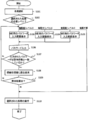
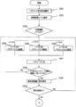
まず、オペレータにより、端末装置20上でアプリケーション211に対する操作(操作表示部23を介した操作)が開始され、いずれかの処理が選択されたものとする(S101)。
アプリケーション211が、オペレータから実行しようとする処理選択を受付ける画面の構成については限定されないものであるが、例えば、図6のようなメニュー画面(以下、「処理選択メニュー画面」と呼ぶ)としてもよい。図6に示す処理選択メニュー画面では、処理ごとに選択を受付けるためのボタンB101~B106が配置されている。
図6に示す処理選択メニュー画面では、処理権限レベル1の入金取引処理を選択するためのボタンB101、処理権限レベル1の出金取引処理を選択するためのボタンB102、処理権限レベル2のカセット構成変更処理を選択するためのボタンB103、処理権限レベル3の認識設定変更処理を選択するためのボタンB104、及び処理権限レベル4のパスワードクリア処理を選択するためのボタンB105が配置されている。
なお、図6の処理選択メニュー画面では、説明を簡易とするための処理権限レベル1~4のそれぞれの処理を受付けるためのボタンを1つのメニュー画面に配置した構成となっているが、アプリケーション211がオペレータから処理選択を受付けるメニュー画面は複数画面を階層化した構成とする等、選択可能な処理の数に応じて適切な構造とするようにしてもよい。
オペレータによりいずれかの処理が選択されると、端末装置20のアプリケーション211は、選択された処理の処理権限レベルを確認する(S102)。例えば、アプリケーション211に、予め各処理の処理権限レベルの情報が登録しておき、アプリケーション211はその情報を参照してオペレータにより選択された処理の処理権限レベルを確認するようにしてもよい。
オペレータに選択された処理が、処理権限レベル1の処理だった場合には、パスワード入力は不要(パスワードが0桁)であるため、アプリケーション211は、パスワード入力を要求せずに後述するステップS110の処理に移行する。
また、選択された処理が処理権限レベル2の処理だった場合、アプリケーション211は、処理権限レベル2に対応する4桁のパスワード入力を受付けるためのパスワード入力画面を操作表示部23に表示させる(S103)。
さらに、選択された処理が処理権限レベル3の処理だった場合、アプリケーション211は、処理権限レベル3に対応する6桁のパスワード入力を受付けるためのパスワード入力画面を操作表示部23に表示させる(S104)。
さらにまた、選択された処理が処理権限レベル4の処理だった場合、アプリケーション211は、処理権限レベル4に対応する8桁のパスワード入力を受付けるためのパスワード入力画面を操作表示部23に表示させる(S105)。
次に、アプリケーション211は、ステップS103~S104のいずれかで表示したパスワード入力画面でパスワード入力を受付ける(S106)。
図7A~7Cは、パスワード入力画面の構成例について示した説明図である。
図7Aは、4桁のパスワード入力を受付けるためのパスワード入力画面の構成例である。図7Aでは、4桁のパスワード入力を受付けるためのフィールドF201と、パスワード入力の完了を受付けるOKボタンB201が配置されている。
図7Bは、6桁のパスワード入力を受付けるためのパスワード入力画面の構成例である。図7Bでは、6桁のパスワード入力を受付けるためのフィールドF202と、パスワード入力の完了を受付けるOKボタンB201が配置されている。
図7Cは、8桁のパスワード入力を受付けるためのパスワード入力画面の構成例である。図7Cでは、8桁のパスワード入力を受付けるためのフィールドF203と、パスワード入力の完了を受付けるOKボタンB201が配置されている。
アプリケーション211は、パスワード入力画面を表示すると、表示したパスワード入力画面に対応する桁数のパスワード入力を受付ける処理を行う。また、図7A~7Cの各パスワード入力画面ではパスワード入力を受付けるフィールドに入力済の数字を表示する構成となっているが、入力済の数字をマスクした表示(例えば、入力済の数字を「*」等の記号に置き換えて表示)とするようにしてもよい。
パスワード入力画面でのパスワードの入力が完了すると、アプリケーション211は、入力されたパスワードの桁数が、表示したパスワード入力画面で入力要求した桁数と一致しているか否かを確認する(S107)。アプリケーション211は、入力されたパスワードが入力要求した桁数と一致しない場合は、上述のステップS103~S105のいずれかに戻って再度同じ桁数のパスワード入力画面を表示する処理から動作する。
また、アプリケーション211は、入力されたパスワードが入力要求した桁数と一致した場合、制御ドライバ212及び通信ドライバ213を介して、現金処理機10の制御部11に認証要求を送信する(S108)。このとき、アプリケーション211は、現金処理機10(制御部11)に対して、入力されたパスワードと、認証を要求する処理権限レベルを通知する。そして、現金処理機10の制御部11は、認証要求を受付けると、通知されたパスワードと、パスワードデータ121に登録されているパスワードを照合して、認証OK又は認証NGを、端末装置20(アプリケーション211)に返答する。
そして、アプリケーション211は、現金処理機10(制御部11)からの返答が認証OKだった場合は、後述するステップS110の処理に移行し、認証NGだった場合は、は、上述のステップS103~S105のいずれかに戻って再度同じ桁数のパスワード入力画面を表示する処理から動作する。
ステップS110に移行すると、アプリケーション211は、上述のステップS101で選択された処理の詳細内容の入力等を受付け、現金処理機10に対して当該処理の実行を要求する命令(コマンド)を送信する。このとき、現金処理機10(制御部11)側でも、処理実行の度に、当該処理に対応する処理権限レベルの認証が成功したか否かを確認し、認証失敗している場合や、当該処理の処理権限レベルと直前に認証成功した処理権限レベルとが一致しない場合等には、端末装置20からの処理実行要求を拒否するようにしてもよい。
以上のような処理により、現金処理機10では、オペレータの処理権限レベルに応じた処理を実行することができる。
次に、端末装置20でオペレータからいずれかの処理権限レベルについてパスワード変更を受付けた場合の動作について図8、図9のフローチャートを用いて説明する。
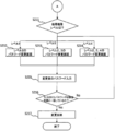
まず、オペレータにより、端末装置20上でアプリケーション211に対する操作(操作表示部23を介した操作)が開始され、パスワード変更の処理が選択されたものとする(S201)。なお、アプリケーション211がパスワード変更の処理の選択を受付けるまでのメニュー画面の構成については種々のメニュー画面の構成を適用することができる。
パスワード変更の処理が選択されると、アプリケーション211は、さらに、パスワード変更をする処理権限レベルの選択を受付ける操作画面(以下、「処理権限レベル選択画面」と呼ぶ)を、操作表示部23に表示させ、オペレータから処理権限レベルを受付ける(S202)。
処理権限レベル選択画面の具体的な構成について限定されないものであるが、例えば、図10のような操作画面としてもよい。図10に示す処理権限レベル選択画面では、処理権限レベルの選択を受付けるためのボタンB301~B303が配置されている。
図10に示す処理権限レベル選択画面では、処理権限レベル2を選択するためのボタンB301、処理権限レベル3を選択するためのボタンB302、処理権限レベル4を選択するためのボタンB303が配置されている。
処理権限レベル選択画面で処理権限レベルが選択(いずれかのボタンが押下)されると、端末装置20のアプリケーション211は、選択された処理権限レベルを確認する(S203)。
選択された処理の処理権限レベルが2だった場合、アプリケーション211は、処理権限レベル2に対応する4桁のパスワード入力を受付けるためのパスワード入力画面(図7Aの操作画面)を操作表示部23に表示させる(S204)。
また、選択された処理の処理権限レベルが3だった場合、アプリケーション211は、処理権限レベル3に対応する6桁のパスワード入力を受付けるためのパスワード入力画面(図7Bの操作画面)を操作表示部23に表示させる(S205)。
さらにまた、選択された処理が処理権限レベル4の処理だった場合、アプリケーション211は、処理権限レベル4に対応する8桁のパスワード入力を受付けるためのパスワード入力画面(図7Cの操作画面)を操作表示部23に表示させる(S206)。
次に、アプリケーション211は、ステップS204~S206のいずれかで表示したパスワード入力画面でパスワード入力を受付ける(S207)。
パスワード入力画面でのパスワードの入力が完了すると、アプリケーション211は、入力されたパスワードの桁数が、表示したパスワード入力画面で入力要求した桁数と一致しているか否かを確認する(S208)。アプリケーション211は、入力されたパスワードが入力要求した桁数と一致しない場合は、上述のステップS204~S206のいずれかに戻って再度同じ桁数のパスワード入力画面を表示する処理から動作する。
一方、入力されたパスワードが入力要求した桁数と一致した場合、アプリケーション211は、制御ドライバ212及び通信ドライバ213を介して、現金処理機10の制御部11に照合要求(認証要求)を送信する(S209)。そして、現金処理機10の制御部11は、照合要求を受付けると、通知されたパスワードと、パスワードデータ121に登録されているパスワードを照合して、照合OK又は照合NGを、端末装置20(アプリケーション211)に返答する。
そして、アプリケーション211は、現金処理機10(制御部11)からの返答を確認し(S210)、現金処理機10(制御部11)からの返答が照合OKだった場合は、後述するステップS211の処理に移行し、照合NGだった場合は、上述のステップS204~S206のいずれかに戻って再度同じ桁数のパスワード入力画面を表示する処理から動作する。
現金処理機10(制御部11)からの照合結果がOKだった場合、アプリケーション211は、照合結果がOKだった処理権限レベルを確認する(S211)。
照合結果OKだった処理権限レベルが2だった場合、アプリケーション211は、処理権限レベル2の変更後のパスワード(4桁のパスワード)入力を受付けるためのパスワード変更画面を操作表示部23に表示させる(S212)。
また、照合結果OKだった処理権限レベルが3だった場合、アプリケーション211は、処理権限レベル2、3の変更後のパスワード(4桁及び6桁のパスワード)入力を受付けるためのパスワード変更画面を操作表示部23に表示させる(S213)。
さらに、照合結果OKだった処理権限レベルが4だった場合、アプリケーション211は、処理権限レベル2、3、4の変更後のパスワード(4桁、6桁、及び8桁のパスワード)入力を受付けるためのパスワード変更画面を操作表示部23に表示させる(S214)。
次に、アプリケーション211は、ステップS212~S214のいずれかで表示したパスワード変更画面で変更後のパスワード入力を受付ける(S215)。
図11A~11Cは、パスワード変更画面の構成例について示した説明図である。
図11Aは、処理権限レベル2(4桁)のパスワード入力を受付けるためのパスワード変更画面の構成例である。図11Aでは、4桁のパスワード入力を受付けるためのフィールドF401と、パスワード入力の完了を受付けるOKボタンB401が配置されている。
図11Bは、処理権限レベル2(4桁)、処理権限レベル4(6桁)のパスワード入力を受付けるためのパスワード変更画面の構成例である。図11Bでは、4桁のパスワード入力を受付けるためのフィールドF401と、6桁のパスワード入力を受付けるためのフィールドF402と、パスワード入力の完了を受付けるOKボタンB401が配置されている。
図11Cは、処理権限レベル2(4桁)、処理権限レベルル4(6桁)、及び処理権限レベル4(8桁)のパスワード入力を受付けるためのパスワード変更画面の構成例である。図11Cでは、4桁のパスワード入力を受付けるためのフィールドF401と、6桁のパスワード入力を受付けるためのフィールドF402と、8桁のパスワード入力を受付けるためのフィールドF403と、パスワード入力の完了を受付けるOKボタンB401が配置されている。
アプリケーション211は、パスワード変更画面を表示すると、表示したパスワード変更画面に対応する桁数のパスワード入力を受付ける処理を行う。なお、処理権限レベル3、4のパスワード変更画面では、同時に複数レベルのパスワード入力を受付けるようにしてもよい。また、図11A~11Cの各パスワード変更画面ではパスワード入力を受付けるフィールドに入力済の数字を表示する構成となっているが、入力済の数字をマスクした表示(例えば、入力済の数字を「*」等の記号に置き換えて表示)するようにしてもよい。
パスワード変更画面でのパスワードの入力が完了すると、アプリケーション211は、各フィールドについて、入力されたパスワードの桁数が入力要求した桁数と一致しているか否かを確認する(S216)。アプリケーション211は、パスワード変更画面で入力されたパスワードが入力要求した桁数と一致しない場合は、上述のステップS212~S214のいずれかに戻って再度同じ処理権限レベルのパスワード変更画面を表示する処理から動作する。
また、アプリケーション211は、入力された全てのパスワードが入力要求した桁数と一致した場合、制御ドライバ212及び通信ドライバ213を介して、現金処理機10の制御部11に入力されたパスワード変更要求(コマンド)を送信する(S217)。現金処理機10(制御部11)は、パスワード変更要求が通知されると、通知された処理権限レベルのパスワードを変更(パスワードデータ121の内容を変更)する。
以上のように、現金処理システム1000では、現金処理機10に登録するパスワードデータ121(処理権限レベルごとのパスワード)を変更することができる。図11A~11Cに示すように、現金処理システム1000では、オペレータの処理権限レベル以下のパスワードについてのみ変更可能な構成となっている。
(A-3)第1の実施形態の効果
第1の実施形態によれば、以下のような効果を奏することができる。
第1の実施形態によれば、以下のような効果を奏することができる。
現金処理システム1000では、処理権限レベルごとに異なる桁数のパスワードを適用することで、オペレータは自身の権限に応じた処理のみしか実行できなくなる。これにより、現金処理システム1000では、仮に一部のパスワード(例えば、処理権限レベル2、3のパスワード)について漏えいしたとしても、現金処理機10の全ての処理を不正に実行できるわけではないため、よりセキュリティを向上させることができる。
また、第1の実施形態の現金処理システム1000では、高い処理権限レベルほど桁数の多いパスワードを設定して、高い処理権限レベルほど高いセキュリティを確保することができる。例えば、全ての処理権限レベルに対して、一律に4桁のパスワードを設定可能とした場合、低い処理権限しか持たないオペレータ(低い処理権限レベルのパスワードしか知らないオペレータ)により、入力されたパスワードが、偶然にそれより高い処理権限レベルのパスワードと一致して、不正に処理実行できてしまうこと等を防止することができる。
上述の図5~図10では、端末装置20からの指示(コマンド)に従って処理実行する例について説明したが、現金処理機10自体の操作表示部14で、上述の図5~図10と同様の操作画面を表示してオペレータからの処理実行の指示を受付けるようにしてもよい。その場合、現金処理機の制御部11は、自装置内のパスワードデータ121を参照して、処理権限レベルを用いたパスワード認証処理を行うことになる。このように第1の実施形態では、現金処理機10自体の操作表示部14を用いて、オペレータから処理実行の指示を受付ける場合でも、上述の端末装置20で受付ける場合と同様にセキュリティを向上させる効果を奏する。
(B)第2の実施形態
以下、本開示による現金処理機、端末装置、及び現金処理システムの第2の実施形態を、図面を参照しながら詳述する。
以下、本開示による現金処理機、端末装置、及び現金処理システムの第2の実施形態を、図面を参照しながら詳述する。
(B-1)第2の実施形態の構成
図12は、第2の実施形態に係る現金処理システム1000Aの構成について示したブロック図である。図12では、上述の図1と同一部分又は対応部分には、同一符号又は対応符号を付している。以下では、第2の実施形態について、第1の実施形態との差異のみを説明する。
図12は、第2の実施形態に係る現金処理システム1000Aの構成について示したブロック図である。図12では、上述の図1と同一部分又は対応部分には、同一符号又は対応符号を付している。以下では、第2の実施形態について、第1の実施形態との差異のみを説明する。
第2の実施形態では、現金処理機10、端末装置20が、それぞれ現金処理機10A、端末装置20Aに置き換わっている点で第1の実施形態と異なっている。
第2の実施形態の端末装置20Aでは、アプリケーション211に、現金処理機10Aでパスワードモード(処理権限レベルを用いたパスワード認証)を有効とするか否かを設定するためのパスワードモード設定情報211Aが登録(保持)されている点で第1の実施形態と異なっている。パスワードモード設定情報211Aは、現金処理機10Aでパスワードモードを有効とする値、又は現金処理機10Aでパスワードモードを無効とする値のいずれかの値が設定されるフラグ情報である。
また、第2の実施形態の現金処理機10Aでは、記憶部12に、パスワードモード設定情報211Aと同様の形式のパスワードモード設定情報122が登録(保持)されている点で、第1の実施形態と異なっている。現金処理機10Aの制御部11は、初回に起動(例えば、工場出荷時の状態や、工場出荷時の状態に初期化された状態で起動)したとき、端末装置20Aにアクセスしてパスワードモード設定情報211Aの値を取得し、記憶部12のパスワードモード設定情報122に反映させる処理を行う。
第2の実施形態の現金処理機10Aでは、記憶部12がパスワードモード設定情報122を保持する設定値保持部として機能する。また、第2の実施形態の端末装置20Aでは、制御部21のアプリケーション211が、パスワードモード設定情報211Aを保持する設定値保持部として機能する。
(B-2)第2の実施形態の動作
次に、以上のような構成を有する第2の実施形態の現金処理システム1000Aの動作を説明する。
次に、以上のような構成を有する第2の実施形態の現金処理システム1000Aの動作を説明する。
以下では、第2の実施形態の現金処理システム1000Aの動作について、第1の実施形態との差異を説明する。
図13は、現金処理機10A(制御部11)が初回に起動するときの動作について示したフローチャートである。
なお、現金処理機10A(制御部11)において、パスワードモード設定情報122の初期の設定値(初回起動時前の設定値)は、パスワードモードを無効とする値であるものとする。
現金処理機10Aの制御部11は、初回に起動すると、端末装置20A(アプリケーション211)にアクセスして、端末装置20A側に設定されているパスワードモード設定情報211Aの設定値を要求して読み込む(S301)。
次に、制御部11は、取得したパスワードモード設定情報211Aの設定値を確認し(S302)、取得した設定値が、パスワードモードを有効とする値だった場合にのみ、自装置側のパスワードモード設定情報122を変更(パスワードモードを有効とする値に変更)する(S303)。また、このとき、制御部11は、自装置においてパスワードモードを有効に変更した旨の通知を端末装置20A側に送信するようにしてもよい。次回起動時以後、現金処理機10は、パスワードモードを有効とした状態で動作することになる。
次に、制御部11は、自装置の電源をオフ(又は電源オフを伴わないシャットダウン)して(S304)初回起動時の動作を終了する。上述のステップS303で、パスワードモードを有効とする設定に変更されていた場合、現金処理機10(制御部11)は、次回の起動以後にパスワードモードを有効とした状態で起動することになる。
次に、端末装置20Aのアプリケーション211が起動するときの動作について図14のフローチャートを用いて説明する。
端末装置20Aのアプリケーション211は、起動する際、パスワードモード設定情報211Aの内容を確認する(S401)。
そして、パスワードモード設定情報211Aにパスワードモードを無効とする旨の値が設定されていた場合、アプリケーション211は、以後パスワードモードを無効とした状態で動作する(S402)。この場合、アプリケーション211は、オペレータから操作を受付けた処理について、特にパスワードによる認証を行わずに実行(処理権限レベルに関わらず実行)することになる。
そして、パスワードモード設定情報211Aでパスワードモードを有効とする旨の値が設定されていた場合、アプリケーション211は、以後パスワードモードを有効とした状態で動作する(S403)。この場合、アプリケーション211は、オペレータから操作を受付けた処理について、処理権限レベルを用いたパスワードによる認証を経た上で実行(第1の実施形態と同様の処理を実行)することになる。
また、アプリケーション211は、現金処理機10Aが起動する際に、現金処理機10Aに対してパスワードモード設定情報122の設定値(パスワードモードを有効とする旨の値又は無効とする旨の値)を通知(コマンド送信)する。アプリケーション211が現金処理機10Aに対してパスワードモード設定情報122の設定値を通知する契機については限定されないものである。例えば、アプリケーション211は、インタフェース30を介して現金処理機10Aの状態を監視して、現金処理機10Aが起動(電源ON)したことを検知したときに、パスワードモード設定情報122の設定値を通知(コマンド送信)するようにしてもよいし、現金処理機10Aからの要求に応じて、パスワードモード設定情報122の設定値を通知(コマンド送信)するようにしてもよい。
次に、現金処理機10A(制御部11)が2回目以後(初回の次以後)に起動する際の動作について図15のフローチャートを用いて説明する。
現金処理機10A(制御部11)は、2回目以後(図13のフローチャートの処理以後)に起動すると、まず、自装置に設定されているパスワードモード設定情報122を参照し、パスワードモードが有効となっているか無効となっているかを確認する(S501)。
そして、パスワードモード設定情報122でパスワードモードを無効とする旨の値が設定されていた場合、制御部21は、以後パスワードモードを無効とした状態で動作する(S506)。この場合、制御部21は、操作表示部14又は端末装置20Aから受付けた処理の実行に際して、特にパスワードによる認証を行わずに実行(処理権限レベルに関わらず実行)することになる。
一方、パスワードモード設定情報122でパスワードモードを有効とする旨の値が設定されていた場合、制御部21は、端末装置20A(アプリケーション211)からパスワードモードの設定値(パスワードモード設定情報211Aの設定値)のコマンドを受信し(S502)、当該コマンドの設定値を確認する(S503)。なお、上述の通り、制御部21が、端末装置20Aからパスワードモードの設定値のコマンド受信を行う契機については限定されないものである。
端末装置20A(アプリケーション211)から受信したコマンドが、パスワードモードを無効とする内容だった場合、制御部21は、端末装置20A(アプリケーション211)にエラー(パスワードモード無効の状態では処理の実行ができない旨のエラー)を通知し(S504)、上述のステップS502に戻って動作する。すなわち、制御部21は、現金処理機10A側(パスワードモード設定情報122)で、パスワードモードが有効に設定されている場合、端末装置20A側でもパスワードモードが有効でなければ処理の実行を拒否(コマンドを全て拒否)する状態となる。また、このとき、現金処理機10Aでは、操作表示部14から直接操作を受付けた場合でも、処理の実行を拒否する。
一方、端末装置20A(アプリケーション211)から受信したコマンドが、パスワードモードを有効とする内容だった場合、制御部21は、以後、パスワードモードを有効とした状態で動作を開始する(S505)。この場合、制御部21は、オペレータから操作を受付けた処理について、処理権限レベルを用いたパスワードによる認証を経た上で実行(第1の実施形態と同様の処理を実行)することになる。
(B-3)第2の実施形態の効果
第2の実施形態によれば、第1の実施形態の効果に加えて、以下のような効果を奏するができる。
第2の実施形態によれば、第1の実施形態の効果に加えて、以下のような効果を奏するができる。
第2の実施形態の現金処理システム1000Aでは、現金処理機10Aのパスワードモード設定情報122を、パスワードモードを有効とする値に設定しておけば、不正行為者による操作(処理実行)を防止することができる。
例えば、現金処理機10Aが接地された銀行で、銀行業務終了後に、不正行為者が当該現金処理機10Aを操作して出金等の処理を実行しようとした場合を想定する。この場合、端末装置20Aが電源オフの状態であれば、現金処理機10Aは端末装置20Aからパスワードモード設定情報211Aの設定値を取得することができないため、不正行為者は現金処理機10Aの操作表示部23を操作したとしても、何の処理も実行させることができない状態となる。
(C)他の実施形態
本開示は、上記の各実施形態に限定されるものではなく、以下に例示するような変形実施形態も挙げることができる。
本開示は、上記の各実施形態に限定されるものではなく、以下に例示するような変形実施形態も挙げることができる。
(C-1)上記の各実施形態において、端末装置のアプリケーションは、全ての処理権限レベルの操作が可能な構成となっているが、処理権限レベルごとに起動するアプリケーション(プログラム)を分けることでセキュリティ性を向上させることが可能となる。例えば、例えば、権限低(処理権限レベル2)専用のソフトウェア、権限中(処理権限レベル3)専用のソフトウェアのように、権限毎に実行できる取引を分けたプログラム構成としることにより、さらにセキュリティを向上させることが可能となる。
Claims (10)
- 現金を処理する現金処理機であって、
前記現金処理機で処理を実行する際の処理権限のレベルごとに異なる桁数のパスワードを保持するパスワード保持部と、
指示された処理を実行する際に、前記処理に対応する処理権限レベルのパスワードを用いた認証処理を行うよう構成された認証部と、
前記認証部で認証が成功した処理を実行するよう構成された処理実行部と
を有する、現金処理機。 - 前記パスワード保持部は、処理権限レベルが上がるほど桁数の多いパスワードを保持する、請求項1に記載の現金処理機。
- 前記パスワード保持部は、最も低い処理権限レベルについてはパスワードを保持しない、請求項2に記載の現金処理機。
- 前記処理実行部は、最も低い処理権限レベルの処理については、前記認証部による認証を必要とせずに処理を実行するよう構成された、請求項3に記載の現金処理機。
- 前記認証部は外部の端末装置から指示された処理を実行する際に、前記処理に対応する処理権限レベルのパスワードを用いた認証処理を行うよう構成された、請求項1~4のいずれかに記載の現金処理機。
- 処理実行の際にパスワード認証を有効とするか否かを示すパスワードモード設定情報を保持する設定値保持部をさらに有し、
前記設定値保持部は、前記現金処理機が最初に起動する際に、前記端末装置で保持しているパスワードモード設定情報を取得して保持する
請求項5に記載の現金処理機。 - 前記処理実行部は、前記現金処理機が2回目以後に起動する際に、前記設定値保持部でパスワードモード設定情報を確認し、前記設定値保持部が保持するパスワードモード設定情報がパスワード認証を有効とする旨の値だった場合、前記認証部で認証が成功した処理を実行し、前記設定値保持部が保持するパスワードモード設定情報がパスワード認証を無効とする旨の値だった場合、前記認証部による認証を必要とせずに指示された処理を実行するよう構成された、請求項6に記載の現金処理機。
- 前記処理実行部は、前記現金処理機が2回目以後に起動する際に、前記設定値保持部でパスワードモード設定情報を確認し、前記設定値保持部が保持するパスワードモード設定情報がパスワード認証を有効とする旨の値だった場合、前記端末装置で保持しているパスワードモード設定情報の取得を試み、前記端末装置からパスワード認証を有効とする旨の値のパスワードモード設定情報が取得できなかった場合、処理実行の指示を受けても前記処理を実行しないよう構成された、請求項7に記載の現金処理機。
- 現金を処理する現金処理機に指示する処理を受付ける端末装置であって、
前記現金処理機に対して実行させる処理の入力を受ける処理受付部と、
前記処理受付部で受付けた処理の処理権限レベルに対応する桁数のパスワード入力を受けるパスワード受付部と、
前記パスワード受付部が入力を受けたパスワードを用いた認証を前記現金処理機に要求するよう構成された、認証要求部と、
前記認証要求部で要求した認証が成功した場合に、前記処理受付部が入力を受けた処理実行を前記現金処理機に指示するよう構成された、処理実行指示部と
を有する、端末装置。 - 請求項1に記載の現金処理機と、
請求項9に記載の端末装置と、
を有する現金処理システム。
Applications Claiming Priority (2)
| Application Number | Priority Date | Filing Date | Title |
|---|---|---|---|
| JP2016-033251 | 2016-02-24 | ||
| JP2016033251A JP6617603B2 (ja) | 2016-02-24 | 2016-02-24 | 現金処理機、端末装置、及び現金処理システム |
Publications (1)
| Publication Number | Publication Date |
|---|---|
| WO2017145504A1 true WO2017145504A1 (ja) | 2017-08-31 |
Family
ID=59685060
Family Applications (1)
| Application Number | Title | Priority Date | Filing Date |
|---|---|---|---|
| PCT/JP2016/087672 Ceased WO2017145504A1 (ja) | 2016-02-24 | 2016-12-16 | 現金処理機、端末装置、及び現金処理システム |
Country Status (2)
| Country | Link |
|---|---|
| JP (1) | JP6617603B2 (ja) |
| WO (1) | WO2017145504A1 (ja) |
Citations (5)
| Publication number | Priority date | Publication date | Assignee | Title |
|---|---|---|---|---|
| JPS63661B2 (ja) * | 1982-04-30 | 1988-01-08 | Nissan Motor | |
| JPH07146903A (ja) * | 1993-11-24 | 1995-06-06 | Fujitsu Ltd | ローカルセキュリティを有する取引システム |
| JP2000315276A (ja) * | 1999-04-30 | 2000-11-14 | Hitachi Ltd | 現金自動取引装置 |
| JP2003008801A (ja) * | 2002-03-26 | 2003-01-10 | Kyocera Mita Corp | 画像形成装置 |
| JP2009042890A (ja) * | 2007-08-07 | 2009-02-26 | Konica Minolta Business Technologies Inc | 情報処理装置、データ保護方法およびデータ保護プログラム |
Family Cites Families (1)
| Publication number | Priority date | Publication date | Assignee | Title |
|---|---|---|---|---|
| JPS63661A (ja) * | 1986-06-19 | 1988-01-05 | Omron Tateisi Electronics Co | カ−ド処理システム |
-
2016
- 2016-02-24 JP JP2016033251A patent/JP6617603B2/ja not_active Expired - Fee Related
- 2016-12-16 WO PCT/JP2016/087672 patent/WO2017145504A1/ja not_active Ceased
Patent Citations (5)
| Publication number | Priority date | Publication date | Assignee | Title |
|---|---|---|---|---|
| JPS63661B2 (ja) * | 1982-04-30 | 1988-01-08 | Nissan Motor | |
| JPH07146903A (ja) * | 1993-11-24 | 1995-06-06 | Fujitsu Ltd | ローカルセキュリティを有する取引システム |
| JP2000315276A (ja) * | 1999-04-30 | 2000-11-14 | Hitachi Ltd | 現金自動取引装置 |
| JP2003008801A (ja) * | 2002-03-26 | 2003-01-10 | Kyocera Mita Corp | 画像形成装置 |
| JP2009042890A (ja) * | 2007-08-07 | 2009-02-26 | Konica Minolta Business Technologies Inc | 情報処理装置、データ保護方法およびデータ保護プログラム |
Also Published As
| Publication number | Publication date |
|---|---|
| JP2017151705A (ja) | 2017-08-31 |
| JP6617603B2 (ja) | 2019-12-11 |
Similar Documents
| Publication | Publication Date | Title |
|---|---|---|
| US8376219B1 (en) | Banking system controlled responsive to data bearing records | |
| JP6803692B2 (ja) | 現金処理システム、現金処理方法及び携帯端末 | |
| CN105229709B (zh) | 安全性系统 | |
| CN102081819A (zh) | 纸币处理装置 | |
| US7922080B1 (en) | Automated banking machine that operates responsive to data bearing records | |
| JP2012108796A (ja) | 自動取引システム、自動取引方法、および自動取引装置 | |
| CN101681533A (zh) | 货币处理机、货币处理机系统以及控制方法 | |
| WO2006067858A1 (ja) | 貨幣入出金機 | |
| JP2010092316A (ja) | 時間外取引方法及び時間外取引システム | |
| JP6617603B2 (ja) | 現金処理機、端末装置、及び現金処理システム | |
| JP5527988B2 (ja) | 貨幣処理システムおよび貨幣処理方法 | |
| EP3627422A1 (en) | Automated teller machine with three modes | |
| JP5202152B2 (ja) | 現金処理システム | |
| JP7541794B2 (ja) | 貨幣処理装置、貨幣処理装置の異常解消方法およびコンピュータプログラム | |
| KR102250014B1 (ko) | 카드결제 기능이 구비된 무인 화폐교환장치 | |
| JP7306166B2 (ja) | 金銭処理装置及び金銭処理方法 | |
| JP2020009380A (ja) | 通帳取引処理システム、自動取引装置、通帳取引方法および通帳取引プログラム | |
| CN101488259A (zh) | 交易处理装置 | |
| JP2018160154A (ja) | 現金自動取引装置、情報処理方法、及び情報処理プログラム | |
| JPH0636211B2 (ja) | 自動取引装置 | |
| KR102002945B1 (ko) | Cen/xfs 비표준 기반 어플리케이션 인증 장치 및 그 제어방법, 그리고 금융기기 | |
| JP6480313B2 (ja) | 取引装置、取引方法および取引プログラム | |
| JP6459499B2 (ja) | 現金処理装置および現金処理方法 | |
| JP2013145489A (ja) | 現金類処理装置、現金類処理方法、及びプログラム | |
| EP4358046A1 (en) | Valuable medium processing apparatus and valuable medium processing method |
Legal Events
| Date | Code | Title | Description |
|---|---|---|---|
| NENP | Non-entry into the national phase |
Ref country code: DE |
|
| 121 | Ep: the epo has been informed by wipo that ep was designated in this application |
Ref document number: 16891659 Country of ref document: EP Kind code of ref document: A1 |
|
| 122 | Ep: pct application non-entry in european phase |
Ref document number: 16891659 Country of ref document: EP Kind code of ref document: A1 |