WO2017141649A1 - ウェビング巻取装置 - Google Patents
ウェビング巻取装置 Download PDFInfo
- Publication number
- WO2017141649A1 WO2017141649A1 PCT/JP2017/002556 JP2017002556W WO2017141649A1 WO 2017141649 A1 WO2017141649 A1 WO 2017141649A1 JP 2017002556 W JP2017002556 W JP 2017002556W WO 2017141649 A1 WO2017141649 A1 WO 2017141649A1
- Authority
- WO
- WIPO (PCT)
- Prior art keywords
- pinion
- spool
- torsion shaft
- outer peripheral
- lock base
- Prior art date
Links
Images


Classifications
-
- B—PERFORMING OPERATIONS; TRANSPORTING
- B60—VEHICLES IN GENERAL
- B60R—VEHICLES, VEHICLE FITTINGS, OR VEHICLE PARTS, NOT OTHERWISE PROVIDED FOR
- B60R22/00—Safety belts or body harnesses in vehicles
- B60R22/34—Belt retractors, e.g. reels
- B60R22/46—Reels with means to tension the belt in an emergency by forced winding up
- B60R22/4628—Reels with means to tension the belt in an emergency by forced winding up characterised by fluid actuators, e.g. pyrotechnic gas generators
-
- B—PERFORMING OPERATIONS; TRANSPORTING
- B60—VEHICLES IN GENERAL
- B60R—VEHICLES, VEHICLE FITTINGS, OR VEHICLE PARTS, NOT OTHERWISE PROVIDED FOR
- B60R22/00—Safety belts or body harnesses in vehicles
- B60R22/28—Safety belts or body harnesses in vehicles incorporating energy-absorbing devices
-
- B—PERFORMING OPERATIONS; TRANSPORTING
- B60—VEHICLES IN GENERAL
- B60R—VEHICLES, VEHICLE FITTINGS, OR VEHICLE PARTS, NOT OTHERWISE PROVIDED FOR
- B60R22/00—Safety belts or body harnesses in vehicles
- B60R22/34—Belt retractors, e.g. reels
- B60R22/36—Belt retractors, e.g. reels self-locking in an emergency
- B60R22/405—Belt retractors, e.g. reels self-locking in an emergency responsive to belt movement and vehicle movement
-
- B—PERFORMING OPERATIONS; TRANSPORTING
- B60—VEHICLES IN GENERAL
- B60R—VEHICLES, VEHICLE FITTINGS, OR VEHICLE PARTS, NOT OTHERWISE PROVIDED FOR
- B60R22/00—Safety belts or body harnesses in vehicles
- B60R22/34—Belt retractors, e.g. reels
- B60R22/46—Reels with means to tension the belt in an emergency by forced winding up
- B60R22/4676—Reels with means to tension the belt in an emergency by forced winding up comprising energy-absorbing means operating between belt reel and retractor frame
-
- B—PERFORMING OPERATIONS; TRANSPORTING
- B60—VEHICLES IN GENERAL
- B60R—VEHICLES, VEHICLE FITTINGS, OR VEHICLE PARTS, NOT OTHERWISE PROVIDED FOR
- B60R22/00—Safety belts or body harnesses in vehicles
- B60R22/28—Safety belts or body harnesses in vehicles incorporating energy-absorbing devices
- B60R2022/286—Safety belts or body harnesses in vehicles incorporating energy-absorbing devices using deformation of material
- B60R2022/287—Safety belts or body harnesses in vehicles incorporating energy-absorbing devices using deformation of material of torsion rods or tubes
-
- B—PERFORMING OPERATIONS; TRANSPORTING
- B60—VEHICLES IN GENERAL
- B60R—VEHICLES, VEHICLE FITTINGS, OR VEHICLE PARTS, NOT OTHERWISE PROVIDED FOR
- B60R22/00—Safety belts or body harnesses in vehicles
- B60R22/34—Belt retractors, e.g. reels
- B60R22/46—Reels with means to tension the belt in an emergency by forced winding up
- B60R22/4628—Reels with means to tension the belt in an emergency by forced winding up characterised by fluid actuators, e.g. pyrotechnic gas generators
- B60R2022/4642—Reels with means to tension the belt in an emergency by forced winding up characterised by fluid actuators, e.g. pyrotechnic gas generators the gas directly propelling a flexible driving means, e.g. a plurality of successive masses, in a tubular chamber
- B60R2022/4647—Reels with means to tension the belt in an emergency by forced winding up characterised by fluid actuators, e.g. pyrotechnic gas generators the gas directly propelling a flexible driving means, e.g. a plurality of successive masses, in a tubular chamber the driving means being a belt, a chain or the like
-
- B—PERFORMING OPERATIONS; TRANSPORTING
- B60—VEHICLES IN GENERAL
- B60R—VEHICLES, VEHICLE FITTINGS, OR VEHICLE PARTS, NOT OTHERWISE PROVIDED FOR
- B60R22/00—Safety belts or body harnesses in vehicles
- B60R22/34—Belt retractors, e.g. reels
- B60R22/46—Reels with means to tension the belt in an emergency by forced winding up
- B60R2022/468—Reels with means to tension the belt in an emergency by forced winding up characterised by clutching means between actuator and belt reel
Definitions
- the present invention relates to a webbing take-up device.
- webbing take-up device in which a pinion for rotating the spool in the take-up direction in the event of a vehicle emergency is arranged on the outer peripheral side of the shaft portion of the lock base fixed to the torsion shaft (as an example, JP 2012-509808 A) See the publication).
- a webbing take-up device in order to suppress the length in the axial direction of the device, the portion where the torsion shaft is fitted in the shaft portion of the lock base and the pinion overlap at the axial position of the device.
- the object of the present invention is to obtain a webbing take-up device that can suppress the diameter of the pinion part in consideration of the above facts.
- a webbing take-up device includes a spool in which a webbing of a seat belt device is taken up by being rotated in the take-up direction, and is accommodated in the spool and disposed along the axial direction of the spool.
- the first pinion constituting portion includes a first member constituting one side in a width direction of a pinion portion that rotates in the winding direction by a moving member that moves with a fluid pressure in a vehicle emergency, the first member, It is arranged between the torsion shaft and fixed to the first member, and is fixed to the torsion shaft.
- the outer peripheral portion is arranged in parallel with the first pinion component.
- a second member in which a second pinion component that forms the other side in the width direction of the pinion part is formed, and one of the first member and the second member is pulled out opposite to the winding direction in the event of a vehicle emergency And a lock portion that restricts rotation in the direction.
- the webbing take-up device of the first aspect of the present disclosure in a vehicle emergency, one of the first member and the second member is restricted from rotating in the pull-out direction opposite to the take-up direction by the lock portion.
- the first pinion component formed on the outer peripheral portion of the first member constitutes one side in the width direction of the pinion portion that rotates in the winding direction by the moving member that moves with the fluid pressure in the event of a vehicle emergency.
- the second member disposed between the first member and the torsion shaft is fixed to the first member and is also fixed to the torsion shaft. Are formed side by side, and a second pinion constituent part that forms the other side in the width direction of the pinion part is formed.
- the diameter of a pinion part can be restrained compared with the case where a separate pinion is arrange
- the webbing take-up device is, in the configuration of the first aspect, a cylindrical shape in which the torsion shaft is fitted in the second member and is provided coaxially with the pinion portion.
- the bottom of the pinion portion is set at a position radially inward of the outer peripheral surface of the insertion portion.
- the root of the pinion portion is set at a position radially inward of the outer peripheral surface of the insertion portion, and thus the diameter of the pinion portion can be further suppressed. .
- the second member in the configuration of the first or second aspect, has a hole formed through the axial center thereof, and the second member is formed inside the hole. Is formed with an annular seat portion facing the torsion shaft side, and the first member is provided with a protruding portion that is accommodated in the hole portion and caulked and fixed to the seat portion.
- the protruding portion of the first member is accommodated in the hole portion of the second member and is caulked and fixed to the seat portion formed in the hole portion.
- the first member is firmly fixed to the second member in a state of being prevented from being pulled out in the thrust direction.
- the second member has a hole formed through the axial center thereof,
- the one member includes a protruding portion accommodated in a state of being retained in the hole portion, and the outer peripheral side of the protruding portion of the first member is recessed on the side opposite to the spool side.
- a fitting recess formed in an annular shape around the protruding portion and formed with a plurality of female splines on the inner peripheral surface on the radially outer side is provided, and the second member has a side opposite to the spool side.
- a fitting convex portion is provided which is formed in an annular shape around the protruding portion and is formed with a plurality of male splines engaging with the plurality of female splines on the outer peripheral surface.
- the male spline of the fitting convex portion of the second member is connected to the female spline of the fitting concave portion of the first member on the outer peripheral side of the protruding portion of the first member. They mesh with each other and are prevented from rotating on the outer peripheral side of the protrusion. For this reason, torque load can be satisfactorily transmitted between the first member and the second member.
- the webbing take-up device has the torsion shaft fitted in the second member and is provided coaxially with the fitting convex portion.
- a cylindrical insertion portion is formed, and the outer peripheral surface of the fitting convex portion of the second member is located at a position radially outward from the outer peripheral surface of the portion inserted into the insertion portion in the torsion shaft. Is set.
- the outer peripheral surface of the fitting convex portion of the second member is radially outward from the outer peripheral surface of the portion of the torsion shaft that is inserted into the insertion portion. Since the position is set, the torque load from the torsion shaft side can be transmitted better.
- the webbing take-up device according to the present invention has an excellent effect that the diameter of the pinion part can be suppressed.
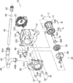
- FIG. 5B is a cross-sectional view showing a part of the webbing take-up device of FIG. 1, and is a cross-sectional view taken along line 2-2 of FIG. 5A.
- FIG. 4 is an exploded perspective view showing a part of the webbing take-up device of FIG. 1 in an enlarged state as seen from a direction different from FIG. 3.
- FIG. 5 is a sectional view taken along line 5B-5B in FIG. It is sectional drawing which shows a part of webbing winding device concerning the 1st modification. It is sectional drawing which shows a part of webbing winding device concerning the 2nd modification.
- a webbing take-up device according to an embodiment of the present invention will be described with reference to FIGS.
- the one axial end side of the spool 14 in the webbing take-up device 10 is indicated by an arrow A
- the other axial end side of the spool 14 is indicated by an arrow B.
- FIG. 1 is an exploded perspective view showing a part of the webbing take-up device 10 according to this embodiment.
- the webbing take-up device 10 includes a frame 12.
- the frame 12 is fixed to a vehicle lower side portion of a center pillar (not shown) constituting a vehicle body skeleton portion in the vehicle.
- the frame 12 includes leg plates 12A and 12B, and the leg plate 12A and the leg plate 12B are opposed to each other.
- the frame 12 is provided with a substantially cylindrical spool 14.
- the center axis direction of the spool 14 is along the opposing direction of the leg plate 12A and the leg plate 12B, and the spool 14 is rotatable around the center axis.
- the longitudinal base end portion of the long belt-like webbing 16 of the seat belt device is locked to the spool 14, and the webbing 16 is elongated in the longitudinal direction by rotating the spool 14 in the winding direction (arrow C direction). It is wound on the spool 14 from the direction base end side.
- the front end side of the webbing 16 in the longitudinal direction extends from the spool 14 toward the vehicle upper side, and the front end side of the webbing 16 in the longitudinal direction passes through a slit hole formed in a through anchor (not shown) on the vehicle upper side of the frame 12. It is turned to the lower side of the vehicle.
- the through anchor is supported by the center pillar.
- the front end of the webbing 16 in the longitudinal direction is locked to an anchor plate (not shown).
- the anchor plate is formed of a metal plate material such as a steel material, and is fixed to a vehicle floor (not shown) or a skeleton member of a sheet (not shown) corresponding to the webbing take-up device 10.
- the vehicle seat belt device to which the webbing retractor 10 is applied includes a buckle device (not shown).
- the buckle device is provided on the inner side in the vehicle width direction of the seat to which the webbing retractor 10 is applied.
- a tongue (not shown) provided on the webbing 16 is engaged with the buckle device, so that the webbing 16 is mounted on the occupant's body. .
- a spring housing 22 is provided on the outer surface side (outer side of the frame) of the leg plate 12A of the frame 12.
- a spool urging portion (not shown) such as a mainspring spring is provided inside the spring housing 22, and the spool 14 is moved in the winding direction (arrow C direction) of the webbing 16 by the urging force of the spool urging portion. It is energized.
- a lock mechanism 24 is provided on the outer surface side (outside the frame) of the leg plate 12B of the frame 12.
- the lock mechanism 24 includes a lock base 26 as a first member.
- the lock base 26 is provided on one end side in the axial direction of the spool 14 (see the arrow A direction), is coaxial with the spool 14 and is relatively rotatable, and the rotational force of the spool 14 is transmitted to the center axis of the spool 14. It can be rotated around.
- the lock base 26 is made of die cast in this embodiment.
- the lock mechanism 24 includes a sensor mechanism (not shown).
- the sensor mechanism is well known in, for example, Japanese Patent Application Laid-Open No. 2014-162290, and detailed description thereof is omitted.
- the sensor mechanism is activated in a vehicle emergency such as a vehicle collision.
- a lock pawl 28 as a lock portion provided on the lock base 26 is moved outward in the rotational radius direction of the lock base 26.
- cover plate 30 is fixed to the leg plate 12B of the frame 12 by rivets 32.
- the cover plate 30 is recessed on the opposite side of the frame 12 and includes a plate portion 30A.
- the plate portion 30A of the cover plate 30 is disposed so as to face the leg plate 12B on the outer surface side (outer side of the frame) of the leg plate 12B of the frame 12.
- a ratchet hole 30B as a lock portion is formed through the plate portion 30A of the cover plate 30, and the lock base 26 of the lock mechanism 24 passes through the ratchet hole 30B of the cover plate 30.
- the sensor mechanism of the lock mechanism 24 is operated and the lock pawl 28 of the lock base 26 is moved outward in the rotational radial direction of the lock base 26, the lock pawl 28 engages with the ratchet teeth of the ratchet hole 30B of the cover plate 30. It comes to fit.
- the lock base 26 is restricted from rotating in the pulling-out direction (arrow D direction) opposite to the winding direction in a vehicle emergency.
- the webbing take-up device 10 includes a torsion shaft 18 that constitutes a force limiter.
- the torsion shaft 18 is formed in a rod shape, is accommodated in the axial center portion of the spool 14, and is disposed along the axial direction of the spool 14.
- the axial first end 18A of the torsion shaft 18 is spooled in a state in which relative rotation with respect to the spool 14 is prevented on the side of the other end 14B in the axial direction of the spool 14 (the other end side of the one end 14A in the axial direction). 14 is held.
- a second end 18B in the axial direction of the torsion shaft 18 is connected to the lock base 26 via a connecting member 34 as a second member.
- the connecting member 34 disposed between the lock base 26 and the torsion shaft 18 is fixed to the lock base 26 and to the torsion shaft 18. Thereby, the relative rotation of the torsion shaft 18 with respect to the lock base 26 is prevented, and the lock base 26 is connected to the spool 14 in a state where the relative rotation with respect to the spool 14 is prevented by the connecting member 34 and the torsion shaft 18.
- the connecting member 34 is made of die-cast in this embodiment. Details of the lock base 26 and the connecting member 34 will be described later.
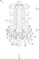
- the webbing take-up device 10 includes a pretensioner 38.
- the pretensioner 38 includes a pipe 40 (cylindrical member).
- the pipe 40 is formed in a substantially cylindrical shape as a whole and has a plurality of curved portions.
- the axial base end portion of the pipe 40 is a micro gas generator mounting portion 40A.
- the micro gas generator mounting portion 40A is supported by a support portion 12C provided on the upper end side of the leg plate 12A of the frame 12.
- a micro gas generator 42 (a gas generation unit which is one mode of a fluid supply unit) is mounted on the micro gas generator mounting unit 40A.
- the micro gas generator 42 is electrically connected to a collision detection sensor (all not shown) provided in the vehicle via an ECU as a control unit.
- a collision detection sensor all not shown
- the micro gas generator 42 is operated by the ECU, and gas that is one mode of the fluid generated in the micro gas generator 42 is supplied to the inside of the pipe 40. .
- the tip end portion in the axial direction of the pipe 40 is a cover plate mounting portion 40B whose opening is directed downward.
- the cover plate attachment portion 40B is attached to a pipe attachment portion 30C provided on the upper portion of the cover plate 30, and is disposed on the inner side in the vehicle width direction (the front side in the drawing) with respect to the center axis of the spool 14.
- the pretensioner 38 includes a rack 46 as a moving member.
- the rack 46 is made of a synthetic resin and is formed in a rod shape with a softer material than the lock base 26 and the connecting member 34.
- the rack 46 is disposed inside the pipe 40.
- a seal ball 44 is disposed between the rack 46 and the micro gas generator 42 inside the pipe 40.
- the rack 46 moves inside the pipe 40 and the inside of the cover plate 30 (that is, on one end side in the axial direction of the spool 14) by the pressure of the fluid supplied from the micro gas generator 42 in an emergency of the vehicle.
- a stopper mounting portion 30D is provided on the outer side in the vehicle width direction (back side in the figure) with respect to the pipe mounting portion 30C.
- a stopper mounting portion 12 ⁇ / b> D is provided at a portion facing the stopper mounting portion 30 ⁇ / b> D of the cover plate 30.
- a flange portion 48B of the rack stopper 48 is disposed between the stopper mounting portion 30D of the cover plate 30 and the stopper mounting portion 12D of the frame 12, and the flange portion 48B is fastened together by the rivet 32.
- the main body 48A of the rack stopper 48 has a bottomed cylindrical shape with an opening directed toward the cover plate 30 and restricts the movement of the rack 46 that has moved inside the cover plate 30.
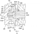
- FIG. 2 is a cross-sectional view of a part of the webbing retractor 10 taken along line 2-2 in FIG. 5A (viewed from the outer surface side of the lock base 26).
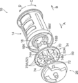
- 3 and 4 are exploded perspective views showing a part of the webbing retractor 10 in an enlarged state.
- a first pinion component 60 constituting one side in the width direction of the pinion portion 50 is formed on the outer periphery of the lock base 26, and a first pinion component 60 is formed on the outer periphery of the connecting member 34.
- a second pinion component 70 is provided which is arranged in parallel with the one pinion component 60 and forms the other side in the width direction of the pinion unit 50.
- the pinion part 50 constituted by the first pinion constituting part 60 and the second pinion constituting part 70 constitutes a part of the pretensioner 38 (see FIG. 1) and includes a plurality of engaging teeth 52.
- a portion configured by the second pinion constituting portion 70 of the engaging teeth 52 is indicated by reference numeral 70 ⁇ / b> A
- a portion constituted by the first pinion constituting portion 60 among the engaging teeth 52 is indicated by reference numeral 60A.
- the engaging teeth 52 are radially formed around the rotation center of the pinion portion 50 at a certain angle.
- the dimension along the rotation circumferential direction of the pinion part 50 in these engagement teeth 52 is set short toward the radial direction outer side of the pinion part 50.
- the engaging teeth 52 of the pinion portion 50 are set to receive a load by the rack 46 that moves from the inside of the pipe 40 shown in FIG.
- the part 50 (refer FIG. 4) rotates in the winding direction (arrow C direction).
- the connecting member 34 is formed with a hole 72 penetrating through the axial center thereof, and an annular seat 72A facing the torsion shaft 18 is formed inside the hole 72. (See FIG. 2) is formed.
- the lock base 26 includes a boss-like protrusion 62 that protrudes toward the torsion shaft 18 and is housed in a state where the lock base 26 is retained in the hole 72 of the connecting member 34.
- the protruding portion 62 of the lock base 26 includes a caulking portion 62 ⁇ / b> A that is caulked and fixed to a seat portion 72 ⁇ / b> A of the connecting member 34.
- a fitting concave portion 64 is provided which is recessed on the opposite side to the spool 14 side and is formed in an annular shape around the protruding portion 62.
- a plurality of female splines 64 ⁇ / b> A are formed on the inner peripheral surface on the radially outer side of the fitting recess 64.
- the connecting member 34 is provided with a fitting convex portion 74 that protrudes in the opposite direction to the spool 14 and is formed in an annular shape around the protruding portion 62. As shown in FIGS.
- a plurality of male splines 74 ⁇ / b> A that mesh with a plurality of female splines 64 ⁇ / b> A of the fitting recesses 64 of the lock base 26 are formed on the outer peripheral surface of the fitting protrusions 74 of the connecting member 34. ing. Thereby, the fitting convex part 74 of the connection member 34 and the fitting concave part 64 of the lock base 26 are fitted.
- the connecting member 34 is formed with a cylindrical insertion portion 76 into which the second end portion 18 ⁇ / b> B of the torsion shaft 18 is inserted.
- the fitted portion 76 is provided coaxially with the pinion portion 50 and is provided coaxially with the fitting convex portion 74.
- a plurality of female splines 76 ⁇ / b> A are formed on the inner peripheral surface of the fitted portion 76.
- the 2nd end part 18B of the torsion shaft 18 and the to-be-inserted part 76 of the connection member 34 are fitting.
- the outer peripheral surface 74 ⁇ / b> M of the fitting convex portion 74 in the connecting member 34 is set at a position radially outward from the outer peripheral surface 18 ⁇ / b> M of the second end portion 18 ⁇ / b> B of the torsion shaft 18. (See the two-dot chain line X).
- the lock base 26 and the connecting member 34 constituting the pinion unit 50 are connected to the spool 14 via the torsion shaft 18 of the force limiter mechanism, and are prevented from rotating relative to the spool 14, so that the pinion unit 50 is wound up.
- the spool 14 shown in FIG. 1 and the like is rotated in the winding direction (arrow C direction).
- the webbing 16 is wound around the spool 14 and the restraining force of the occupant by the webbing 16 is increased.
- the portion on one side in the width direction of the pinion portion 50 is constituted by a first pinion constituting portion 60 formed on the outer peripheral portion of the lock base 26. Further, the portion on the other side in the width direction of the pinion portion 50 is constituted by a second pinion constituting portion 70 formed on the outer peripheral portion of the connecting member 34. For this reason, the diameter of a pinion part can be restrained compared with the case where a separate pinion is arrange
- the protrusion 62 of the lock base 26 is caulked and fixed to a seat 72A formed in the hole 72 by being accommodated in the hole 72 of the connecting member 34. For this reason, the lock base 26 is firmly fixed to the connecting member 34 in a state where the lock base 26 is prevented from being pulled out in the thrust direction. Therefore, the load acting on the pinion portion 50 (see FIG. 2) during the operation of the pretensioner 38 shown in FIG. 1 can be further increased, which can contribute to the performance improvement of the pretensioner 38.
- the fitting convex portion of the connecting member 34 is fitted to the female spline 64 ⁇ / b> A (see FIG. 4) of the fitting concave portion 64 of the lock base 26.
- 74 male splines 74 ⁇ / b> A mesh with each other and are prevented from rotating on the outer peripheral side of the protrusion 62. For this reason, even if a larger force limiter load or a load due to the operation of the pretensioner 38 (see FIG. 1) is applied, the torque load can be transmitted between the connecting member 34 and the lock base 26 favorably. In such a point, performance can be improved.
- the outer peripheral surface 74M of the fitting convex portion 74 in the connecting member 34 is more radially outward than the outer peripheral surface 18M of the second end portion 18B that is fitted in the fitted portion 76 in the torsion shaft 18. It is set (see the two-dot chain line X). For this reason, the torque load from the torsion shaft 18 side can be transmitted better.
- the diameter of the pinion portion 50 can be suppressed.
- a predetermined amount of the webbing 16 can be wound (retracted) when the pretensioner 38 is operated. Therefore, the physique can be reduced and the cost can be reduced.
- the lock base 26 and the connecting member 34 have a large diameter by providing a fitting structure of the fitting concave portion 64 and the fitting convex portion 74. It is possible to suppress the formation of a cylindrical portion (thick wall portion). At the same time, the thickness of each part of the lock base 26 and the connecting member 34 can be made close to the same thickness, and the surface area of the lock base 26 and the connecting member 34 can be increased, so that die casting is performed. The part cooling time at the time can also be kept short. Therefore, productivity can be improved and cost can be suppressed.
- FIG. 6A is a sectional view showing a part of the webbing take-up device according to the first modification.
- FIG. 6B is a sectional view showing a part of the webbing take-up device according to the second modification.
- the lock base 26 includes a protruding portion 80 accommodated in a state of being prevented from being removed from the hole 72 of the connecting member 34.
- a bolt fastening hole 80A is formed in the lock base 26 at a portion including the axial center portion of the protruding portion 80, and a female screw portion is formed on the inner peripheral surface of the bolt fastening hole 80A.
- a shaft portion 82A of a bolt 82 is screwed into the bolt fastening hole 80A from the torsion shaft 18 side.
- the head portion 82 ⁇ / b> B of the bolt 82 is seated on the projecting top surface 80 ⁇ / b> B of the projecting portion 80 and the seat portion 72 ⁇ / b> A of the hole 72.
- the lock base 26 and the connecting member 34 are fastened to each other.
- the second modification shown in FIG. 6B has a configuration substantially similar to that in the above embodiment except that the diameter of the pinion portion 50 is set smaller than that in the above embodiment.
- the same reference numerals as in the above embodiment are given.
- the tooth bottom 52A in the pinion portion 50 is set at a position radially inward of the outer peripheral surface 76M of the fitted portion 76 (see the two-dot chain line Y).
- the diameter of the pinion portion 50 is set smaller, so that the webbing 16 during operation of the pretensioner 38 can be achieved even if the lengths of the pipe 40 and the rack 46 shown in FIG. A predetermined amount can be secured.
- the first member provided with the first pinion component is the lock base 26.
- the second member provided with the second pinion component is the lock base.
- a configuration may be employed in which rotation in the pull-out direction opposite to the winding direction of the lock base is restricted by the lock portion in a vehicle emergency.
- the lock portion in this case is engaged with the external teeth formed on the spool side portion of the outer peripheral portion of the lock base as the second member, and the external teeth when the sensor mechanism is activated in the event of a vehicle emergency.
- a matching lock pawl A configuration in which the lock pawl meshes with the external teeth of the lock base in a vehicle emergency is known in, for example, Japanese Patent Application Laid-Open No. 2011-255814, and detailed description thereof is omitted.
- the coupling structure between the first member and the second member may be different from the structures of the above-described embodiment and the modified example.
Landscapes
- Engineering & Computer Science (AREA)
- Mechanical Engineering (AREA)
- Automotive Seat Belt Assembly (AREA)
Priority Applications (3)
| Application Number | Priority Date | Filing Date | Title |
|---|---|---|---|
| CN201780010732.0A CN108883740B (zh) | 2016-02-17 | 2017-01-25 | 安全带卷取装置 |
| EP17752912.0A EP3418131B1 (en) | 2016-02-17 | 2017-01-25 | Webbing take-up device |
| US16/076,763 US10723311B2 (en) | 2016-02-17 | 2017-01-25 | Webbing take-up device |
Applications Claiming Priority (2)
| Application Number | Priority Date | Filing Date | Title |
|---|---|---|---|
| JP2016028313A JP6579976B2 (ja) | 2016-02-17 | 2016-02-17 | ウェビング巻取装置 |
| JP2016-028313 | 2016-02-17 |
Publications (1)
| Publication Number | Publication Date |
|---|---|
| WO2017141649A1 true WO2017141649A1 (ja) | 2017-08-24 |
Family
ID=59625016
Family Applications (1)
| Application Number | Title | Priority Date | Filing Date |
|---|---|---|---|
| PCT/JP2017/002556 WO2017141649A1 (ja) | 2016-02-17 | 2017-01-25 | ウェビング巻取装置 |
Country Status (5)
| Country | Link |
|---|---|
| US (1) | US10723311B2 (zh) |
| EP (1) | EP3418131B1 (zh) |
| JP (1) | JP6579976B2 (zh) |
| CN (1) | CN108883740B (zh) |
| WO (1) | WO2017141649A1 (zh) |
Families Citing this family (4)
| Publication number | Priority date | Publication date | Assignee | Title |
|---|---|---|---|---|
| JP6620069B2 (ja) * | 2016-06-09 | 2019-12-11 | 株式会社東海理化電機製作所 | ウェビング巻取装置 |
| JP6649848B2 (ja) * | 2016-06-09 | 2020-02-19 | 株式会社東海理化電機製作所 | ウェビング巻取装置 |
| JP7024494B2 (ja) * | 2018-02-23 | 2022-02-24 | 株式会社東海理化電機製作所 | ウェビング巻取装置 |
| JP2021178567A (ja) * | 2020-05-13 | 2021-11-18 | 株式会社東海理化電機製作所 | ウェビング巻取装置 |
Citations (3)
| Publication number | Priority date | Publication date | Assignee | Title |
|---|---|---|---|---|
| US20100013205A1 (en) * | 2008-07-15 | 2010-01-21 | Keller Gerald J | Seat Belt Retractor and Torsion Bar Providing Secondary Load Limiting |
| JP2010018179A (ja) * | 2008-07-11 | 2010-01-28 | Tokai Rika Co Ltd | ウェビング巻取装置 |
| JP2010023754A (ja) * | 2008-07-23 | 2010-02-04 | Tokai Rika Co Ltd | ウェビング巻取装置 |
Family Cites Families (11)
| Publication number | Priority date | Publication date | Assignee | Title |
|---|---|---|---|---|
| US5853135A (en) * | 1997-02-21 | 1998-12-29 | Alliedsignal Inc. | Chain link rack pretensioner |
| BR0012064B1 (pt) * | 1999-06-28 | 2011-01-25 | tensor rotativo com acionamento de corpos de massa. | |
| DE20315870U1 (de) * | 2003-10-15 | 2004-02-26 | Trw Occupant Restraint Systems Gmbh & Co. Kg | Gurtaufroller mit reversiblem Gurtstraffer und Rutschkupplung |
| WO2009123318A1 (en) * | 2008-03-31 | 2009-10-08 | Ashimori Industry Co., Ltd. | Seatbelt retractor |
| US7988084B2 (en) * | 2008-08-21 | 2011-08-02 | Autoliv Asp, Inc. | Device for pretensioning a seatbelt |
| DE102008059387B4 (de) * | 2008-11-27 | 2018-06-28 | Autoliv Development Ab | Gurtaufroller mit einer Kraftbegrenzungseinrichtung und einer Straffeinrichtung |
| US8220735B2 (en) * | 2009-12-22 | 2012-07-17 | Autoliv Asp, Inc. | Adaptive load limiting retractor |
| US20120049500A1 (en) * | 2010-08-31 | 2012-03-01 | Bin Wang | Dual Stage Pretensioning and High Pay-In Capacity Pretensioning Retractor |
| DE102012217261B4 (de) * | 2012-09-25 | 2018-10-11 | Autoliv Development Ab | Gurtstraffer für einen Gurtaufroller |
| CN104554135B (zh) * | 2013-10-09 | 2017-06-06 | 比亚迪股份有限公司 | 安全带卷收器及具有其的安全带装置和汽车 |
| CN104742857A (zh) * | 2013-12-30 | 2015-07-01 | 常州博万达汽车安全设备有限公司 | 具有预紧装置的安全带卷收器 |
-
2016
- 2016-02-17 JP JP2016028313A patent/JP6579976B2/ja active Active
-
2017
- 2017-01-25 US US16/076,763 patent/US10723311B2/en active Active
- 2017-01-25 EP EP17752912.0A patent/EP3418131B1/en active Active
- 2017-01-25 CN CN201780010732.0A patent/CN108883740B/zh active Active
- 2017-01-25 WO PCT/JP2017/002556 patent/WO2017141649A1/ja active Application Filing
Patent Citations (3)
| Publication number | Priority date | Publication date | Assignee | Title |
|---|---|---|---|---|
| JP2010018179A (ja) * | 2008-07-11 | 2010-01-28 | Tokai Rika Co Ltd | ウェビング巻取装置 |
| US20100013205A1 (en) * | 2008-07-15 | 2010-01-21 | Keller Gerald J | Seat Belt Retractor and Torsion Bar Providing Secondary Load Limiting |
| JP2010023754A (ja) * | 2008-07-23 | 2010-02-04 | Tokai Rika Co Ltd | ウェビング巻取装置 |
Non-Patent Citations (1)
| Title |
|---|
| See also references of EP3418131A4 * |
Also Published As
| Publication number | Publication date |
|---|---|
| CN108883740B (zh) | 2021-04-23 |
| JP6579976B2 (ja) | 2019-09-25 |
| EP3418131A1 (en) | 2018-12-26 |
| EP3418131B1 (en) | 2020-09-23 |
| JP2017144891A (ja) | 2017-08-24 |
| US20190047510A1 (en) | 2019-02-14 |
| EP3418131A4 (en) | 2019-06-26 |
| CN108883740A (zh) | 2018-11-23 |
| US10723311B2 (en) | 2020-07-28 |
Similar Documents
| Publication | Publication Date | Title |
|---|---|---|
| WO2017141649A1 (ja) | ウェビング巻取装置 | |
| CN110997423B (zh) | 安全带收卷装置 | |
| US9327681B2 (en) | Belt retractor with two force-limiting devices acting in parallel | |
| WO2017213238A1 (ja) | ウェビング巻取装置 | |
| JP6827043B2 (ja) | ウェビング巻取装置 | |
| JP2019127261A (ja) | シートベルトプリテンションリトラクタアセンブリ | |
| JP4163608B2 (ja) | ウエビング巻取装置 | |
| JP6620069B2 (ja) | ウェビング巻取装置 | |
| EP2765038B1 (en) | Webbing take-up device | |
| US10906503B2 (en) | Webbing take-up device | |
| WO2018116719A1 (ja) | ウェビング巻取装置 | |
| US9132801B2 (en) | Seat belt retractor and method for assembling spindle of seat belt retractor | |
| JP2006137290A (ja) | ウエビング巻取装置 | |
| JP2009184520A (ja) | ウエビング巻取装置 | |
| JP6843182B2 (ja) | ウェビング巻取装置 | |
| JP2006159986A (ja) | シートベルト用リトラクター | |
| JP6542298B2 (ja) | ウェビング巻取装置 | |
| JP6649848B2 (ja) | ウェビング巻取装置 | |
| JP2018177031A (ja) | ウェビング巻取装置及びその製造方法 | |
| JP6393788B2 (ja) | 伝達機構 | |
| JP5602671B2 (ja) | プリテンショナ機構 | |
| JP5714417B2 (ja) | ウェビング巻取装置 | |
| WO2019159686A1 (ja) | ウェビング巻取装置 | |
| JP2010149598A (ja) | ウエビング巻取装置 | |
| JP2005231387A (ja) | ウエビング巻取装置 |
Legal Events
| Date | Code | Title | Description |
|---|---|---|---|
| 121 | Ep: the epo has been informed by wipo that ep was designated in this application |
Ref document number: 17752912 Country of ref document: EP Kind code of ref document: A1 |
|
| NENP | Non-entry into the national phase |
Ref country code: DE |
|
| WWE | Wipo information: entry into national phase |
Ref document number: 2017752912 Country of ref document: EP |
|
| ENP | Entry into the national phase |
Ref document number: 2017752912 Country of ref document: EP Effective date: 20180917 |