WO2017138389A1 - ハイブリッド車両 - Google Patents
ハイブリッド車両 Download PDFInfo
- Publication number
- WO2017138389A1 WO2017138389A1 PCT/JP2017/003206 JP2017003206W WO2017138389A1 WO 2017138389 A1 WO2017138389 A1 WO 2017138389A1 JP 2017003206 W JP2017003206 W JP 2017003206W WO 2017138389 A1 WO2017138389 A1 WO 2017138389A1
- Authority
- WO
- WIPO (PCT)
- Prior art keywords
- engine
- belt
- side pulley
- motor
- motor generator
- Prior art date
- Legal status (The legal status is an assumption and is not a legal conclusion. Google has not performed a legal analysis and makes no representation as to the accuracy of the status listed.)
- Ceased
Links
Images

Classifications
-
- B—PERFORMING OPERATIONS; TRANSPORTING
- B60—VEHICLES IN GENERAL
- B60K—ARRANGEMENT OR MOUNTING OF PROPULSION UNITS OR OF TRANSMISSIONS IN VEHICLES; ARRANGEMENT OR MOUNTING OF PLURAL DIVERSE PRIME-MOVERS IN VEHICLES; AUXILIARY DRIVES FOR VEHICLES; INSTRUMENTATION OR DASHBOARDS FOR VEHICLES; ARRANGEMENTS IN CONNECTION WITH COOLING, AIR INTAKE, GAS EXHAUST OR FUEL SUPPLY OF PROPULSION UNITS IN VEHICLES
- B60K6/00—Arrangement or mounting of plural diverse prime-movers for mutual or common propulsion, e.g. hybrid propulsion systems comprising electric motors and internal combustion engines
- B60K6/20—Arrangement or mounting of plural diverse prime-movers for mutual or common propulsion, e.g. hybrid propulsion systems comprising electric motors and internal combustion engines the prime-movers consisting of electric motors and internal combustion engines, e.g. HEVs
- B60K6/22—Arrangement or mounting of plural diverse prime-movers for mutual or common propulsion, e.g. hybrid propulsion systems comprising electric motors and internal combustion engines the prime-movers consisting of electric motors and internal combustion engines, e.g. HEVs characterised by apparatus, components or means specially adapted for HEVs
- B60K6/36—Arrangement or mounting of plural diverse prime-movers for mutual or common propulsion, e.g. hybrid propulsion systems comprising electric motors and internal combustion engines the prime-movers consisting of electric motors and internal combustion engines, e.g. HEVs characterised by apparatus, components or means specially adapted for HEVs characterised by the transmission gearings
-
- B—PERFORMING OPERATIONS; TRANSPORTING
- B60—VEHICLES IN GENERAL
- B60K—ARRANGEMENT OR MOUNTING OF PROPULSION UNITS OR OF TRANSMISSIONS IN VEHICLES; ARRANGEMENT OR MOUNTING OF PLURAL DIVERSE PRIME-MOVERS IN VEHICLES; AUXILIARY DRIVES FOR VEHICLES; INSTRUMENTATION OR DASHBOARDS FOR VEHICLES; ARRANGEMENTS IN CONNECTION WITH COOLING, AIR INTAKE, GAS EXHAUST OR FUEL SUPPLY OF PROPULSION UNITS IN VEHICLES
- B60K6/00—Arrangement or mounting of plural diverse prime-movers for mutual or common propulsion, e.g. hybrid propulsion systems comprising electric motors and internal combustion engines
- B60K6/20—Arrangement or mounting of plural diverse prime-movers for mutual or common propulsion, e.g. hybrid propulsion systems comprising electric motors and internal combustion engines the prime-movers consisting of electric motors and internal combustion engines, e.g. HEVs
- B60K6/22—Arrangement or mounting of plural diverse prime-movers for mutual or common propulsion, e.g. hybrid propulsion systems comprising electric motors and internal combustion engines the prime-movers consisting of electric motors and internal combustion engines, e.g. HEVs characterised by apparatus, components or means specially adapted for HEVs
- B60K6/38—Arrangement or mounting of plural diverse prime-movers for mutual or common propulsion, e.g. hybrid propulsion systems comprising electric motors and internal combustion engines the prime-movers consisting of electric motors and internal combustion engines, e.g. HEVs characterised by apparatus, components or means specially adapted for HEVs characterised by the driveline clutches
- B60K6/383—One-way clutches or freewheel devices
-
- B—PERFORMING OPERATIONS; TRANSPORTING
- B60—VEHICLES IN GENERAL
- B60K—ARRANGEMENT OR MOUNTING OF PROPULSION UNITS OR OF TRANSMISSIONS IN VEHICLES; ARRANGEMENT OR MOUNTING OF PLURAL DIVERSE PRIME-MOVERS IN VEHICLES; AUXILIARY DRIVES FOR VEHICLES; INSTRUMENTATION OR DASHBOARDS FOR VEHICLES; ARRANGEMENTS IN CONNECTION WITH COOLING, AIR INTAKE, GAS EXHAUST OR FUEL SUPPLY OF PROPULSION UNITS IN VEHICLES
- B60K6/00—Arrangement or mounting of plural diverse prime-movers for mutual or common propulsion, e.g. hybrid propulsion systems comprising electric motors and internal combustion engines
- B60K6/20—Arrangement or mounting of plural diverse prime-movers for mutual or common propulsion, e.g. hybrid propulsion systems comprising electric motors and internal combustion engines the prime-movers consisting of electric motors and internal combustion engines, e.g. HEVs
- B60K6/42—Arrangement or mounting of plural diverse prime-movers for mutual or common propulsion, e.g. hybrid propulsion systems comprising electric motors and internal combustion engines the prime-movers consisting of electric motors and internal combustion engines, e.g. HEVs characterised by the architecture of the hybrid electric vehicle
- B60K6/48—Parallel type
- B60K6/485—Motor-assist type
-
- B—PERFORMING OPERATIONS; TRANSPORTING
- B60—VEHICLES IN GENERAL
- B60K—ARRANGEMENT OR MOUNTING OF PROPULSION UNITS OR OF TRANSMISSIONS IN VEHICLES; ARRANGEMENT OR MOUNTING OF PLURAL DIVERSE PRIME-MOVERS IN VEHICLES; AUXILIARY DRIVES FOR VEHICLES; INSTRUMENTATION OR DASHBOARDS FOR VEHICLES; ARRANGEMENTS IN CONNECTION WITH COOLING, AIR INTAKE, GAS EXHAUST OR FUEL SUPPLY OF PROPULSION UNITS IN VEHICLES
- B60K6/00—Arrangement or mounting of plural diverse prime-movers for mutual or common propulsion, e.g. hybrid propulsion systems comprising electric motors and internal combustion engines
- B60K6/20—Arrangement or mounting of plural diverse prime-movers for mutual or common propulsion, e.g. hybrid propulsion systems comprising electric motors and internal combustion engines the prime-movers consisting of electric motors and internal combustion engines, e.g. HEVs
- B60K6/50—Architecture of the driveline characterised by arrangement or kind of transmission units
- B60K6/54—Transmission for changing ratio
-
- F—MECHANICAL ENGINEERING; LIGHTING; HEATING; WEAPONS; BLASTING
- F16—ENGINEERING ELEMENTS AND UNITS; GENERAL MEASURES FOR PRODUCING AND MAINTAINING EFFECTIVE FUNCTIONING OF MACHINES OR INSTALLATIONS; THERMAL INSULATION IN GENERAL
- F16D—COUPLINGS FOR TRANSMITTING ROTATION; CLUTCHES; BRAKES
- F16D41/00—Freewheels or freewheel clutches
- F16D41/06—Freewheels or freewheel clutches with intermediate wedging coupling members between an inner and an outer surface
-
- F—MECHANICAL ENGINEERING; LIGHTING; HEATING; WEAPONS; BLASTING
- F16—ENGINEERING ELEMENTS AND UNITS; GENERAL MEASURES FOR PRODUCING AND MAINTAINING EFFECTIVE FUNCTIONING OF MACHINES OR INSTALLATIONS; THERMAL INSULATION IN GENERAL
- F16H—GEARING
- F16H7/00—Gearings for conveying rotary motion by endless flexible members
- F16H7/02—Gearings for conveying rotary motion by endless flexible members with belts; with V-belts
-
- Y—GENERAL TAGGING OF NEW TECHNOLOGICAL DEVELOPMENTS; GENERAL TAGGING OF CROSS-SECTIONAL TECHNOLOGIES SPANNING OVER SEVERAL SECTIONS OF THE IPC; TECHNICAL SUBJECTS COVERED BY FORMER USPC CROSS-REFERENCE ART COLLECTIONS [XRACs] AND DIGESTS
- Y02—TECHNOLOGIES OR APPLICATIONS FOR MITIGATION OR ADAPTATION AGAINST CLIMATE CHANGE
- Y02T—CLIMATE CHANGE MITIGATION TECHNOLOGIES RELATED TO TRANSPORTATION
- Y02T10/00—Road transport of goods or passengers
- Y02T10/60—Other road transportation technologies with climate change mitigation effect
- Y02T10/62—Hybrid vehicles
Definitions
- the present disclosure relates to a hybrid vehicle including a hybrid system having an engine and a motor generator, which are power sources for driving the vehicle, and a control device.
- HEV hybrid vehicle
- driving force assist ie, powering
- regenerative power generation is performed by the motor generator during inertial traveling or braking (for example, patents). Reference 1).
- HEV of a type in which a motor generator is connected to an engine via a single belt member for power transmission
- the motor generator is driven using the electric power of the battery, so that the engine can be cranked and the engine can be started.
- the width of the belt-like member is set to be thick in order to withstand extremely large power transmitted when the engine is started. Has been.
- the friction caused by the belt-like member is increased, it cannot be said that the fuel efficiency of HEV is sufficiently good.
- the present disclosure has been made in view of the above, and an object of the present disclosure is to reduce the friction caused by a belt-shaped member for power transmission between the engine and the motor generator, thereby improving fuel efficiency. Is to provide.
- a hybrid vehicle includes an engine and a motor generator, which are power sources for running the vehicle, and a hybrid system including a controller, and the engine and the motor generator.
- a power transmission mechanism that transmits power between the first and second belt-like members that transmit power between the engine and the motor generator, and the second belt-like member. Power transmission via the second belt-shaped member from the motor generator to the engine is arranged between at least one of the engine and the motor generator engaged with the belt-shaped member and the second belt-shaped member. Performing the first from the engine to the motor generator Characterized in that it comprises a one-way clutch is not performed power transmission through the belt-shaped member.
- the power when power is transmitted from the motor generator to the engine at the time of starting or powering, that is, when large power is transmitted, the power is transmitted by a total of two belt-shaped members. can do.
- power transmission through the second belt-like member is not performed by the one-way clutch. Power can be transmitted by the first belt-like member.
- a hybrid vehicle of a type in which a motor generator is connected to an engine via a single belt member for power transmission not only at start-up and power running but also at regenerative power generation and power Even when there is no transmission of power, two belt-like members are used not only when power is transmitted with one thick belt-like member, but also during regenerative power generation or when there is no power transmission at the time of starting and powering Friction caused by the first belt-like member and the second belt-like member can be reduced as compared with a hybrid vehicle that transmits power. Thereby, fuel consumption can be improved.
- the second belt-shaped member is engaged with an engine-side pulley connected to the engine and a motor-side pulley connected to the motor generator, and the one-way clutch is engaged with the second belt-shaped member. It can be set as the structure incorporated in at least one of the said engine side pulley and the said motor side pulley which were engaged.
- the one-way clutch is built in at least one of the engine side pulley and the motor side pulley engaged with the second belt-like member, the physique of the power transmission mechanism can be made compact. Thereby, even if there is little space, a power transmission mechanism can be arrange
- the width of the second belt-shaped member may be narrower than the width of the first belt-shaped member.
- the friction caused by the second belt-shaped member can be reduced as compared with the case where the width of the second belt-shaped member is the same as the width of the first belt-shaped member. Thereby, fuel consumption can be improved.
- the one-way clutch may be built in both the engine-side pulley and the motor-side pulley engaged with the second belt-like member.
- the power transmission mechanism further includes a first engine side pulley connected to the output shaft of the engine, a second engine side pulley connected to the output shaft of the engine, and the second engine here.
- a side pulley is disposed closer to the distal end side of the output shaft than the first engine side pulley, and a first motor side pulley connected to the rotating shaft of the motor generator and a first pulley connected to the rotating shaft of the motor generator.
- a second motor side pulley wherein the second motor side pulley is disposed closer to a tip side of the rotating shaft than the first motor side pulley, and the first belt-like member is the first engine side pulley.
- said one-way clutch may be a configuration that is built in at least one of the second engine side pulley and said second motor-side pulley.
- the one-way clutch may be built in both the second engine side pulley and the second motor side pulley.
- the first belt-like member simultaneously drives engine accessories other than the engine and motor generator (for example, an engine cooling fan and a compressor for an air conditioner), whereas the second belt-like member is an engine and motor. Power is transmitted only to the generator. Therefore, when the engine, motor generator, and engine accessory are driven by a single thick belt-like member as in the prior art, the pulley width (pulley width) of the engine accessory is increased. It was necessary to make it wide to fit the width for use. On the other hand, since there are two belt-like members, the width of the pulley of the engine accessory can be reduced to the width of the first belt-like member. Thereby, the pulley of an engine auxiliary machine can be arrange
- FIG. 1 is a configuration diagram of a hybrid vehicle according to an embodiment of the present disclosure.
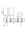
- FIG. 2 is a diagram for explaining the details of the power transmission mechanism.
- FIG. 1 is a configuration diagram of a hybrid vehicle according to an embodiment of the present disclosure.
- the hybrid vehicle (hereinafter referred to as “HEV”) is a vehicle including not only a normal passenger car but also a bus, a truck, and the like, and includes an engine 10 and a motor generator 31 that are controlled in combination according to the driving state of the vehicle.
- a hybrid system 30 is provided.
- the engine 10 and the motor generator 31 have a function as a power source for vehicle travel.
- the engine 10, the motor generator 31, the control device 80, and the power transmission mechanism 120 also have a function as a HEV start acceleration control system.
- the crankshaft 13 is rotationally driven by thermal energy generated by the combustion of fuel in a plurality (four in this example) of cylinders 12 formed in the engine body 11.
- the engine 10 is a diesel engine or a gasoline engine.
- the rotational power of the crankshaft 13 is transmitted to the transmission 20 via a clutch 14 (for example, a wet multi-plate clutch) connected to one end of the crankshaft 13.
- the transmission 20 uses an AMT or an AT that automatically shifts to a target shift speed determined based on the HEV operating state and preset map data using the shift actuator 21.
- the transmission 20 is not limited to an automatic transmission type such as AMT, and may be a manual type in which a driver manually changes gears.
- Rotational power changed by the transmission 20 is transmitted to the differential 23 through the propeller shaft 22 and distributed to the pair of driving wheels 24 as driving force.
- the hybrid system 30 includes a motor generator 31, and an inverter 35, a high voltage battery 32, a DC / DC converter 33, and a low voltage battery 34 that are electrically connected to the motor generator 31 in this order.
- the high voltage battery 32 includes a lithium ion battery and a nickel metal hydride battery.
- the low voltage battery 34 is a lead battery.
- the DC / DC converter 33 has a function of controlling the charge / discharge direction and the output voltage between the high voltage battery 32 and the low voltage battery 34.
- the low voltage battery 34 supplies power to various vehicle electrical components 36.
- Various parameters in the hybrid system 30 such as a current value, a voltage value and a state of charge (SOC) of the battery are detected by the BMS 39 (battery management system).
- the BMS 39 transmits the detection result to the control device 80.
- the motor generator 31 transmits power to and from the engine 10 via a power transmission mechanism 120 attached to the other end of the crankshaft 13 that is the output shaft of the engine body 11. That is, the power transmission mechanism 120 is a mechanism that connects the engine 10 and the motor generator 31 and transmits power between the engine 10 and the motor generator 31.
- the output shaft of the engine body 11 connected to the motor generator 31 is not limited to the crankshaft 13, and may be a transmission shaft between the engine body 11 and the transmission 20, for example. Details of the power transmission mechanism 120 will be described later.
- This motor generator 31 also has a function of cranking.
- the hybrid system 30 described above is controlled by the control device 80. Specifically, the hybrid system 30 is controlled by the control device 80 so that at the time of HEV start, acceleration, etc., at least a part of the driving force by the motor generator 31 supplied with power from the high-voltage battery 32. Assist (ie, powering). On the other hand, the hybrid system 30 performs regenerative power generation by the motor generator 31 during inertia traveling or braking, and converts surplus kinetic energy into electric power to charge the high voltage battery 32. Further, the hybrid system 30 is controlled by the control device 80 so that when the start command for the engine body 11 is received, the motor generator 31 supplied with power from the high voltage battery 32 is driven to crank the engine body 11. By doing so, the engine body 11 is started.
- control device 80 controls the disengagement and connection of the clutch 14, and also controls the gear stage of the transmission 20 by controlling the speed change actuator 21.
- the control device 80 includes a CPU having a function as a control unit for executing various control processes, and a ROM, a RAM, and the like having a function as a storage unit for storing various data and programs used for the operation of the CPU.
- a microcomputer is provided.
- FIG. 2 is a diagram for explaining the details of the power transmission mechanism 120. Specifically, the peripheral portion of the power transmission mechanism 120 is extracted from the HEV and is schematically shown in cross section.
- the power transmission mechanism 120 includes a first engine-side pulley 121, a second engine-side pulley 122, a first motor-side pulley 123, a second motor-side pulley 124, a first belt-like member 125, a second belt-like member 126, and a one-way A clutch 127 is provided.
- the first engine side pulley 121 and the second engine side pulley 122 are connected to the output shaft of the engine 10 (the crankshaft 13 in this embodiment).
- the second engine-side pulley 122 is disposed closer to the distal end side of the crankshaft 13 than the first engine-side pulley 121 (the end side opposite to the engine body 11 side).
- the first motor side pulley 123 and the second motor side pulley 124 are connected to the rotating shaft 37 of the motor generator 31.
- the second motor side pulley 124 is disposed on the tip side of the rotating shaft 37 (the end side opposite to the main body side of the motor generator 31) with respect to the first motor side pulley 123.
- the first belt-like member 125 and the second belt-like member 126 are belts that transmit power between the crankshaft 13 of the engine 10 and the rotating shaft 37 of the motor generator 31. Specifically, the first belt-like member 125 is wound around the outer periphery of the first engine-side pulley 121 and the outer periphery of the second motor-side pulley 124 so that the first engine-side pulley 121 and the second motor-side pulley are wound around. The pulley 124 is engaged.
- the second belt-like member 126 is wound around the outer periphery of the second engine-side pulley 122 and the outer periphery of the second motor-side pulley 124 so that the second engine-side pulley 122, the second motor-side pulley 124, Is engaged.
- the first belt-like member 125 is also engaged with an engine accessory (for example, an engine cooling fan, a compressor for an air conditioner, etc.), and as a result, the power of the engine 10 is transferred to the engine accessory. Also communicate.
- an engine accessory for example, an engine cooling fan, a compressor for an air conditioner, etc.
- V belts are used as specific examples of the first belt-like member 125 and the second belt-like member 126.
- the specific configuration of the first belt-like member 125 and the second belt-like member 126 is not limited to the V belt, and for example, a flat belt or the like can be used.
- each of the first belt-like member 125 and the second belt-like member 126 is such that the motor generator 31 is connected to the output shaft of the engine 10 through a single belt member for power transmission.
- the width is set narrower than the width of the single belt member for power transmission.
- the width of the second belt-like member 126 is set to be narrower than the width of the first belt-like member 125.
- the one-way clutch 127 is disposed between the second belt-shaped member 126 and at least one of the crankshaft 13 of the engine 10 and the rotating shaft 37 of the motor generator 31 with which the second belt-shaped member 126 is engaged.
- two one-way clutches 127 according to the present embodiment are arranged in total, and one one-way clutch 127 is arranged between the crankshaft 13 and the second belt-like member 126, and the other one-way clutch 127 is arranged.
- the clutch 127 is disposed between the rotation shaft 37 of the motor generator 31 with which the second belt-shaped member 126 is engaged and the second belt-shaped member 126.
- one one-way clutch 127 is built in the second engine-side pulley 122 so as to be disposed between the crankshaft 13 and the second belt-like member 126, and the other one-way clutch 127 is By being incorporated in the second motor-side pulley 124, the second motor-side pulley 124 is disposed between the inner peripheral portion of the second motor-side pulley 124 and the rotating shaft 37.
- the one-way clutch 127 performs power transmission from the motor generator 31 to the engine 10 via the second belt-like member 126 (that is, power transmission during starting and powering), and the second belt from the engine 10 to the motor generator 31.
- Power transmission via the shaped member 126 is a clutch that is not performed by idling.
- the specific structure of the one-way clutch 127 is not particularly limited as long as it has such a function, and a known sprag type or cam type one-way clutch (or free wheel) can be used.
- positioning aspect of the one-way clutch 127 is not limited to the arrangement
- the one-way clutch 127 may be incorporated only in one of the second engine side pulley 122 and the second motor side pulley 124.
- the power transmission mechanism 120 when power is transmitted from the motor generator 31 to the engine 10, such as when the engine 10 is started or powered, the first belt-shaped member 125 and the second belt-shaped member 126. Power is transmitted by.
- the one-way clutch 127 causes the second belt-shaped member 126 to be moved. Therefore, power is transmitted only by the first belt-like member 125.
- power transmission is performed between the engine accessory and the engine 10 only by the first belt-like member 125.
- the present embodiment when a large amount of power is transmitted as in the case of starting or powering, a total of 2 of the first belt-like member 125 and the second belt-like member 126. Power can be transmitted by the belt-shaped member.
- the one-way clutch 127 causes the second belt-shaped member 126 to pass through. Since the transmitted power is not performed, the first belt-shaped member 125 can transmit the power.
- the HEV of a type that transmits power with two belt-shaped members not only at the time of starting and powering but also at the time of regenerative power generation is transmitted to the HEV with one thick belt-shaped member.
- the friction caused by the first belt-like member 125 and the second belt-like member 126 can be reduced. Thereby, fuel consumption can be improved.
- the one-way clutch 127 is built in at least one of the second engine-side pulley 122 and the second motor-side pulley 124 engaged with the second belt-shaped member 126, and thus the power transmission mechanism 120.
- the physique can be made compact. Thereby, the power transmission mechanism 120 can be disposed even in a small space.
- the second belt-shaped member 126 does not transmit power during regenerative power generation, so even if the width of the second belt-shaped member 126 is narrower than the width of the first belt-shaped member 125, There is no problem with the durability of the two-belt member 126. Therefore, as described above with reference to FIG. 2, the width of the second belt-shaped member 126 can be made smaller than the width of the first belt-shaped member 125.
- the configuration of the power transmission mechanism 120 is not limited to the above configuration.
- the width of the second belt-shaped member 126 may be the same as the width of the first belt-shaped member 125.
- the width of the second belt-shaped member 126 becomes equal to the width of the first belt-shaped member 125.
- the friction caused by the second belt-like member 126 can be reduced. Thereby, a fuel consumption can be improved more.
- the first belt-like member 125 simultaneously drives engine accessories other than the engine 10 and the motor generator 31 (for example, an engine cooling fan and a compressor for an air conditioner), whereas the second belt-like member 126. Is the power transmission only of the engine 10 and the motor generator 31. Therefore, when the engine 10, the motor generator 31, and the engine auxiliary machine are driven by a single thick belt-like member as in the prior art, the pulley width (pulley width) of the engine auxiliary machine is set to a thick belt. It was necessary to make it wide to fit the width for the shaped member. On the other hand, according to the present embodiment, since there are two belt-like members, the width of the pulley of the engine accessory can be reduced to the width of the first belt-like member 125. Thereby, the pulley of an engine auxiliary machine can be arrange
- the present invention has the effect of reducing the friction caused by the belt-like member for power transmission between the engine and the motor generator and improving the fuel efficiency, and is useful for hybrid vehicles and the like.
Landscapes
- Engineering & Computer Science (AREA)
- Mechanical Engineering (AREA)
- Chemical & Material Sciences (AREA)
- Combustion & Propulsion (AREA)
- Transportation (AREA)
- General Engineering & Computer Science (AREA)
- Hybrid Electric Vehicles (AREA)
- Devices For Conveying Motion By Means Of Endless Flexible Members (AREA)
- Electric Propulsion And Braking For Vehicles (AREA)
Abstract
ハイブリッド車両の動力伝達機構120は、エンジン10とモータージェネレーター31との間の動力を伝達する第1ベルト状部材125及び第2ベルト状部材126と、第2ベルト状部材が係合するエンジン及びモータージェネレーターの少なくとも一方と第2ベルト状部材との間に配置され、モータージェネレーターからエンジンへの第2ベルト状部材を介した動力伝達は行い、エンジンからモータージェネレーターへの第2ベルト状部材を介した動力伝達は行わないワンウェイクラッチ127と、を備えることを特徴とする。
Description
本開示は、車両走行用の動力源であるエンジン及びモータージェネレーターと、制御装置と、を有するハイブリッドシステムを備えたハイブリッド車両に関する。
近年、燃費向上及び環境対策などの観点から、車両の運転状態に応じて複合的に制御されるエンジン及びモータージェネレーターを有するハイブリッドシステムを備えたハイブリッド車両(以下「HEV」という)が注目されている。このHEVにおいては、車両の加速時や発進時には、モータージェネレーターによる駆動力のアシスト(すなわち、力行)が行われる一方で、慣性走行時や制動時においてはモータージェネレーターによる回生発電が行われる(例えば特許文献1参照)。
また、近年、モータージェネレーターがエンジンに1本の動力伝達用のベルト状部材を介して接続されたタイプのHEVも開発されている。なお、このタイプのHEVの場合、エンジンを始動させる際にモータージェネレーターがバッテリーの電力を用いて駆動することで、エンジンをクランキングさせて、エンジンを始動させることができる。
ところで、上記のように、モータージェネレーターが1本のベルト状部材を介してエンジンに接続されたHEVの場合、例えば回生発電時の場合のように、エンジンからモータージェネレーターに動力が伝達される場合には、相対的に小さい動力がベルト状部材を介して伝達される。一方、例えば始動時や力行時の場合のように、モータージェネレーターからエンジンに動力が伝達される場合には、ベルト状部材を介して相対的に大きな動力が伝達される。特に、エンジンの始動時には、モータージェネレーターからエンジンにベルト状部材を介して非常に大きな動力が伝達される。
したがって、1本のベルト状部材を用いてモータージェネレーターとエンジンとの動力伝達を行うHEVにおいては、このエンジンの始動時に伝達される非常に大きな動力に耐えるために、ベルト状部材の幅は太く設定されている。このようなHEVの場合、ベルト状部材よるフリクションが大きくなるので、HEVの燃費は十分に良好であるとはいえない。
本開示は上記のことを鑑みてなされたものであり、その目的は、エンジンとモータージェネレーターとの間の動力伝達用のベルト状部材によるフリクションを低減させて、燃費を向上させることができるハイブリッド車両を提供することにある。
上記の目的を達成するための本開示のハイブリッド車両は、車両走行用の動力源であるエンジン及びモータージェネレーターと、制御装置と、を有するハイブリッドシステムを備えたハイブリッド車両において、前記エンジンと前記モータージェネレーターとの間の動力を伝達する動力伝達機構を備え、前記動力伝達機構は、前記エンジンと前記モータージェネレーターとの間の動力を伝達する第1ベルト状部材及び第2ベルト状部材と、前記第2ベルト状部材が係合する前記エンジン及び前記モータージェネレーターの少なくとも一方と前記第2ベルト状部材との間に配置され、前記モータージェネレーターから前記エンジンへの前記第2ベルト状部材を介した動力伝達は行い、前記エンジンから前記モータージェネレーターへの前記第2ベルト状部材を介した動力伝達は行わないワンウェイクラッチと、を備えることを特徴とする。
本開示によれば、始動時や力行時のようにモータージェネレーターからエンジンに動力が伝達される場合、すなわち、大きな動力が伝達される場合には、合計2本のベルト状部材によって、動力を伝達することができる。一方、回生発電時のようにエンジンからモータージェネレーターに動力が伝達される場合、すなわち、小さな動力が伝達される場合には、ワンウェイクラッチによって第2ベルト状部材を介した動力伝達は行われないので、第1ベルト状部材によって、動力を伝達することができる。
また、モータージェネレーターが力行や回生発電等を行わず、エンジンとモータージェネレーターとの間で動力の伝達がない場合でも、ワンウェイクラッチによって第2ベルト状部材を介した動力伝達は行われないので、第1ベルト状部材によって、動力を伝達することができる。
したがって、本開示によれば、モータージェネレーターがエンジンに1本の動力伝達用のベルト状部材を介して接続されたタイプのハイブリッド車両のように、始動時や力行時のみならず回生発電時や動力の伝達がない場合にも、太い1本のベルト状部材で動力を伝達する場合や、始動時及び力行時のみならず回生発電時や動力の伝達がない場合にも2本のベルト状部材で動力を伝達するタイプのハイブリッド車両に比較して、第1ベルト状部材及び第2ベルト状部材によるフリクションを低減させることができる。これにより、燃費を向上させることができる。
上記構成において、前記第2ベルト状部材は、前記エンジンに接続されたエンジン側プーリーと前記モータージェネレーターに接続されたモーター側プーリーとに係合し、前記ワンウェイクラッチは、前記第2ベルト状部材に係合した前記エンジン側プーリー及び前記モーター側プーリーの少なくとも一方に内蔵されている構成とすることができる。
この構成によれば、ワンウェイクラッチが第2ベルト状部材に係合したエンジン側プーリー及びモーター側プーリーの少なくとも一方に内蔵されているので、動力伝達機構の体格をコンパクトにすることができる。これにより、少ないスペースであっても、動力伝達機構を配置することができる。
上記構成において、前記第2ベルト状部材の幅は前記第1ベルト状部材の幅よりも狭い構成とすることができる。
この構成によれば、第2ベルト状部材の幅が第1ベルト状部材の幅と同じである場合に比較して、第2ベルト状部材によるフリクションを低減させることができる。これにより、燃費を向上させることができる。
上記構成において、前記ワンウェイクラッチは、前記第2ベルト状部材に係合した前記エンジン側プーリー及び前記モーター側プーリーの両方に内蔵されている構成とすることができる。
上記構成において、前記動力伝達機構はさらに、前記エンジンの出力軸に接続される第1エンジン側プーリーと、前記エンジンの前記出力軸に接続される第2エンジン側プーリーと、ここで前記第2エンジン側プーリーは前記第1エンジン側プーリーよりも前記出力軸の先端側に配置され、前記モータージェネレーターの回転軸に接続される第1モーター側プーリーと、前記モータージェネレーターの前記回転軸に接続される第2モーター側プーリーと、を備え、ここで前記第2モーター側プーリーは前記第1モーター側プーリーよりも前記回転軸の先端側に配置され、前記第1ベルト状部材は、前記第1エンジン側プーリーと前記第1モーター側プーリーとに係合し、前記第2ベルト状部材は、前記第2エンジン側プーリーと前記第2モーター側プーリーとに係合し、前記ワンウェイクラッチは、前記第2エンジン側プーリー及び前記第2モーター側プーリーの少なくとも一方に内蔵されている構成とすることができる。
上記構成において、前記ワンウェイクラッチは、前記第2エンジン側プーリー及び前記第2モーター側プーリーの両方に内蔵されている構成とすることができる。
なお、第1ベルト状部材はエンジンやモータージェネレーター以外のエンジン補機(例えばエンジン冷却ファンや、エアーコンディショナー用のコンプレッサ)を同時に駆動しているのに対して、第2ベルト状部材はエンジンとモータージェネレーターのみの動力伝達となる。このことから、従来のように、太い1本のベルト状部材でエンジン、モータージェネレーター及びエンジン補機を駆動している場合には、エンジン補機のプーリーの幅(プーリー幅)を太いベルト状部材用の幅に合うように広くする必要があった。これに対して、本開示によれば、ベルト状部材が2本になっているので、エンジン補機のプーリーの幅を第1ベルト状部材の幅にまで縮小することができる。これにより、エンジン補機のプーリーを小スペースで配置することができる。
本開示によれば、エンジンとモータージェネレーターとの間の動力伝達用のベルト状部材によるフリクションを低減させて、燃費を向上させることができる。
以下に、本開示の実施の形態について、図面を参照して説明する。図1は、本開示の実施形態からなるハイブリッド車両の構成図である。このハイブリッド車両(以下「HEV」という)は、普通乗用車のみならず、バスやトラックなどを含む車両であり、車両の運転状態に応じて複合的に制御されるエンジン10、及びモータージェネレーター31を有するハイブリッドシステム30を備えている。
なお、エンジン10及びモータージェネレーター31は、車両走行用の動力源としての機能を有している。なお、エンジン10、モータージェネレーター31、制御装置80、及び動力伝達機構120は、HEVの発進加速時制御システムとしての機能も有している。
エンジン10においては、エンジン本体11に形成された複数(この例では4個)の気筒12内における燃料の燃焼により発生した熱エネルギーにより、クランクシャフト13が回転駆動される。このエンジン10には、ディーゼルエンジンやガソリンエンジンが用いられる。クランクシャフト13の回転動力は、クランクシャフト13の一端部に接続するクラッチ14(例えば、湿式多板クラッチなど)を介してトランスミッション20に伝達される。
トランスミッション20には、HEVの運転状態と予め設定されたマップデータとに基づいて決定された目標変速段へ、変速用アクチュエーター21を用いて自動的に変速するAMT又はATが用いられている。なお、トランスミッション20は、AMTのような自動変速式に限るものではなく、ドライバーが手動で変速するマニュアル式であってもよい。
トランスミッション20で変速された回転動力は、プロペラシャフト22を通じてデファレンシャル23に伝達され、一対の駆動輪24にそれぞれ駆動力として分配される。
ハイブリッドシステム30は、モータージェネレーター31と、このモータージェネレーター31に順に電気的に接続するインバーター35、高電圧バッテリー32、DC/DCコンバーター33及び低電圧バッテリー34とを有している。
高電圧バッテリー32としては、リチウムイオンバッテリーやニッケル水素バッテリーが好ましく例示される。また、低電圧バッテリー34には鉛バッテリーが用いられる。
DC/DCコンバーター33は、高電圧バッテリー32と低電圧バッテリー34との間における充放電の方向及び出力電圧を制御する機能を有している。また、低電圧バッテリー34は、各種の車両電装品36に電力を供給する。
このハイブリッドシステム30における種々のパラメータ、例えば、電流値、電圧値やバッテリーの充電状態(state of charge;SOC)などは、BMS39(バッテリーマネージメントシステム)により検出される。BMS39は検出結果を制御装置80に伝える。
モータージェネレーター31は、エンジン本体11の出力軸であるクランクシャフト13の他端部に取り付けられた動力伝達機構120を介して、エンジン10との間で動力を伝達する。すなわち、動力伝達機構120はエンジン10とモータージェネレーター31とを接続するとともに、エンジン10とモータージェネレーター31との間の動力を伝達する機構である。なお、モータージェネレーター31に接続するエンジン本体11の出力軸は、クランクシャフト13に限定されるものではなく、例えばエンジン本体11とトランスミッション20との間の伝達軸であってもよい。なお、動力伝達機構120の詳細は後述する。
このモータージェネレーター31は、クランキングを行う機能も有している。
上述したハイブリッドシステム30は制御装置80によって制御される。具体的にはハイブリッドシステム30は、制御装置80に制御されることで、HEVの発進時、加速時等には、高電圧バッテリー32から電力を供給されたモータージェネレーター31により駆動力の少なくとも一部をアシストする(すなわち力行する)。一方、ハイブリッドシステム30は、慣性走行時や制動時においては、モータージェネレーター31による回生発電を行い、余剰の運動エネルギーを電力に変換して高電圧バッテリー32を充電する。またハイブリッドシステム30は、制御装置80に制御されることで、エンジン本体11の始動指令を受信した場合に高電圧バッテリー32から電力を供給されたモータージェネレーター31が駆動してエンジン本体11をクランキングさせることで、エンジン本体11を始動させる。
また制御装置80は、ハイブリッドシステム30の他に、クラッチ14の切断及び接続を制御するとともに、変速用アクチュエーター21を制御することでトランスミッション20のギア段も制御する。この制御装置80は、各種の制御処理を実行する制御部としての機能を有するCPUと、CPUの動作に用いられる各種データやプログラム等を記憶する記憶部としての機能を有するROM、RAM等とを有するマイクロコンピュータを備えている。
続いて動力伝達機構120の詳細について説明する。図2は動力伝達機構120の詳細を説明するための図であり、具体的には、HEVのうち動力伝達機構120の周辺部を抜き出して模式的に断面図示したものである。動力伝達機構120は、第1エンジン側プーリー121、第2エンジン側プーリー122、第1モーター側プーリー123、第2モーター側プーリー124、第1ベルト状部材125、第2ベルト状部材126、及びワンウェイクラッチ127を備えている。
第1エンジン側プーリー121及び第2エンジン側プーリー122は、エンジン10の出力軸(本実施形態ではクランクシャフト13)に接続されている。なお、第2エンジン側プーリー122は、第1エンジン側プーリー121よりもクランクシャフト13の先端側(エンジン本体11の側とは反対側の端部側)に配置されている。
第1モーター側プーリー123及び第2モーター側プーリー124は、モータージェネレーター31の回転軸37に接続されている。なお、第2モーター側プーリー124は、第1モーター側プーリー123よりも回転軸37の先端側(モータージェネレーター31の本体側とは反対側の端部側)に配置されている。
第1ベルト状部材125及び第2ベルト状部材126は、エンジン10のクランクシャフト13とモータージェネレーター31の回転軸37との間の動力を伝達するベルトである。具体的には第1ベルト状部材125は、第1エンジン側プーリー121の外周部と第2モーター側プーリー124の外周部とに巻き付けられるようにして、第1エンジン側プーリー121と第2モーター側プーリー124とに係合している。また第2ベルト状部材126は、第2エンジン側プーリー122の外周部と第2モーター側プーリー124の外周部とに巻き付けられるようにして、第2エンジン側プーリー122と第2モーター側プーリー124とに係合している。
また本実施形態において、第1ベルト状部材125は、エンジン補機(例えばエンジン冷却ファンや、エアーコンディショナー用のコンプレッサ等)にも係合しており、その結果、エンジン10の動力をエンジン補機にも伝達している。
なお、本実施形態においては、第1ベルト状部材125及び第2ベルト状部材126の具体例として、Vベルトを用いている。但し、第1ベルト状部材125及び第2ベルト状部材126の具体的構成はVベルトに限定されるものではなく、例えば平ベルト等を用いることもできる。
また、第1ベルト状部材125及び第2ベルト状部材126のそれぞれの幅は、モータージェネレーター31がエンジン10の出力軸に1本の動力伝達用のベルト状部材を介して接続されたタイプのHEVに用いられる、この1本の動力伝達用のベルト状部材の幅よりも狭く設定されている。
また本実施形態においては、第2ベルト状部材126の幅は第1ベルト状部材125の幅よりも狭く設定されている。
ワンウェイクラッチ127は、第2ベルト状部材126が係合するエンジン10のクランクシャフト13及びモータージェネレーター31の回転軸37の少なくとも一方と、第2ベルト状部材126との間に配置されている。具体的には本実施形態に係るワンウェイクラッチ127は合計で2個配置されており、一方のワンウェイクラッチ127はクランクシャフト13と第2ベルト状部材126との間に配置されており、他方のワンウェイクラッチ127は第2ベルト状部材126が係合するモータージェネレーター31の回転軸37と第2ベルト状部材126との間に配置されている。より具体的には、一方のワンウェイクラッチ127は第2エンジン側プーリー122に内蔵されることで、クランクシャフト13と第2ベルト状部材126との間に配置されており、他方のワンウェイクラッチ127は第2モーター側プーリー124に内蔵されることで、第2モーター側プーリー124の内周部と回転軸37との間に配置されている。
このワンウェイクラッチ127は、モータージェネレーター31からエンジン10への第2ベルト状部材126を介した動力伝達(すなわち始動時及び力行時の動力伝達)は行い、エンジン10からモータージェネレーター31への第2ベルト状部材126を介した動力伝達(すなわち回生発電時の動力伝達)は空回りすることにより行わないクラッチである。このような機能を有するものであれば、ワンウェイクラッチ127の具体的な構造は特に限定されるものではなく、公知のスプラグ式やカム式のワンウェイクラッチ(またはフリーホイール)を用いることができる。
なお、ワンウェイクラッチ127の配置態様は、図2に示すような第2エンジン側プーリー122及び第2モーター側プーリー124の両方に内蔵される配置態様に限定されるものではない。例えばワンウェイクラッチ127は、第2エンジン側プーリー122及び第2モーター側プーリー124のいずれか一方にのみ内蔵されていてもよい。
上述した動力伝達機構120によれば、エンジン10の始動時や力行時のように、モータージェネレーター31からエンジン10に動力が伝達される場合は、第1ベルト状部材125及び第2ベルト状部材126によって動力が伝達される。一方、回生発電時のようにエンジン10からモータージェネレーター31に動力が伝達される場合やエンジン10とモータージェネレーター31との間の動力伝達がない場合は、ワンウェイクラッチ127によって第2ベルト状部材126を介した動力伝達は禁止されるので、第1ベルト状部材125のみによって動力が伝達される。なお、エンジン10とモータージェネレーター31との間の動力伝達がない場合には、第1ベルト状部材125のみによって、エンジン補機とエンジン10との間で動力伝達が行われる。
以上説明したように、本実施形態によれば、始動時や力行時の場合のように、大きな動力が伝達される場合には、第1ベルト状部材125及び第2ベルト状部材126の合計2本のベルト状部材によって、動力を伝達することができる。一方、回生発電時の場合のように、小さな動力が伝達される場合や、エンジン10とモータージェネレーター31との間の動力伝達がない場合には、ワンウェイクラッチ127によって第2ベルト状部材126を介した動力伝達は行われないので、第1ベルト状部材125によって、動力を伝達することができる。したがって、本実施形態によれば、モータージェネレーター31がエンジン10に1本の動力伝達用のベルト状部材を介して接続されたタイプのHEVのように、始動時や力行時のみならず回生発電時の場合にも、太い1本のベルト状部材で動力を伝達する場合や、始動時及び力行時のみならず回生発電時の場合にも2本のベルト状部材で動力を伝達するタイプのHEVに比較して、第1ベルト状部材125及び第2ベルト状部材126によるフリクションを低減させることができる。これにより、燃費を向上させることができる。
また本実施形態によれば、ワンウェイクラッチ127は、第2ベルト状部材126に係合した第2エンジン側プーリー122及び第2モーター側プーリー124の少なくとも一方に内蔵されているので、動力伝達機構120の体格をコンパクトにすることができる。これにより、少ないスペースであっても、動力伝達機構120を配置することができる。
また、本実施形態によれば、回生発電時において第2ベルト状部材126は動力を伝達しないので、第2ベルト状部材126の幅を第1ベルト状部材125の幅より狭くしても、第2ベルト状部材126の耐久性に問題は生じない。したがって、図2で前述したように、第2ベルト状部材126の幅を第1ベルト状部材125の幅よりも狭くすることができる。
但し、動力伝達機構120の構成は上記構成に限定されるものではなく、例えば第2ベルト状部材126の幅は第1ベルト状部材125の幅と同じであってもよい。しかしながら、本実施形態のように第2ベルト状部材126の幅を第1ベルト状部材125の幅よりも狭くすることにより、第2ベルト状部材126の幅が第1ベルト状部材125の幅と同じ場合に比較して、第2ベルト状部材126によるフリクションを低減させることができる。これにより、燃費をより向上させることができる。
なお、第1ベルト状部材125はエンジン10やモータージェネレーター31以外のエンジン補機(例えばエンジン冷却ファンや、エアーコンディショナー用のコンプレッサ)を同時に駆動しているのに対して、第2ベルト状部材126はエンジン10とモータージェネレーター31のみの動力伝達となる。このことから、従来のように、太い1本のベルト状部材でエンジン10、モータージェネレーター31及びエンジン補機を駆動している場合には、エンジン補機のプーリーの幅(プーリー幅)を太いベルト状部材用の幅に合うように広くする必要があった。これに対して、本実施形態によれば、ベルト状部材が2本になっているので、エンジン補機のプーリーの幅を第1ベルト状部材125の幅にまで縮小することができる。これにより、エンジン補機のプーリーを小スペースで配置することができる。
以上本開示の好ましい実施形態について説明したが、本開示はかかる特定の実施形態に限定されるものではなく、特許請求の範囲に記載された本開示の要旨の範囲内において、種々の変形・変更が可能である。
本出願は、2016年2月8日付で出願された日本国特許出願(特願2016-021556)に基づくものであり、その内容はここに参照として取り込まれる。
本発明は、エンジンとモータージェネレーターとの間の動力伝達用のベルト状部材によるフリクションを低減させて、燃費を向上させることができるという効果を有し、ハイブリッド車両等に有用である。
10 エンジン
13 クランクシャフト(出力軸)
31 モータージェネレーター
37 回転軸
120 動力伝達機構
121 第1エンジン側プーリー
122 第2エンジン側プーリー
123 第1モーター側プーリー
124 第2モーター側プーリー
125 第1ベルト状部材
126 第2ベルト状部材
13 クランクシャフト(出力軸)
31 モータージェネレーター
37 回転軸
120 動力伝達機構
121 第1エンジン側プーリー
122 第2エンジン側プーリー
123 第1モーター側プーリー
124 第2モーター側プーリー
125 第1ベルト状部材
126 第2ベルト状部材
Claims (6)
- 車両走行用の動力源であるエンジン及びモータージェネレーターと、制御装置と、を有するハイブリッドシステムを備えたハイブリッド車両において、
前記エンジンと前記モータージェネレーターとの間の動力を伝達する動力伝達機構を備え、
前記動力伝達機構は、
前記エンジンと前記モータージェネレーターとの間の動力を伝達する第1ベルト状部材及び第2ベルト状部材と、
前記第2ベルト状部材が係合する前記エンジン及び前記モータージェネレーターの少なくとも一方と前記第2ベルト状部材との間に配置され、前記モータージェネレーターから前記エンジンへの前記第2ベルト状部材を介した動力伝達は行い、前記エンジンから前記モータージェネレーターへの前記第2ベルト状部材を介した動力伝達は行わないワンウェイクラッチと、を備えることを特徴とするハイブリッド車両。 - 前記第2ベルト状部材は、前記エンジンに接続されたエンジン側プーリーと前記モータージェネレーターに接続されたモーター側プーリーとに係合し、
前記ワンウェイクラッチは、前記第2ベルト状部材に係合した前記エンジン側プーリー及び前記モーター側プーリーの少なくとも一方に内蔵されている請求項1記載のハイブリッド車両。 - 前記ワンウェイクラッチは、前記第2ベルト状部材に係合した前記エンジン側プーリー及び前記モーター側プーリーの両方に内蔵されている請求項2記載のハイブリッド車両。
- 前記動力伝達機構はさらに、
前記エンジンの出力軸に接続される第1エンジン側プーリーと、
前記エンジンの前記出力軸に接続される第2エンジン側プーリーと、ここで前記第2エンジン側プーリーは前記第1エンジン側プーリーよりも前記出力軸の先端側に配置され、
前記モータージェネレーターの回転軸に接続される第1モーター側プーリーと、
前記モータージェネレーターの前記回転軸に接続される第2モーター側プーリーと、を備え、ここで前記第2モーター側プーリーは前記第1モーター側プーリーよりも前記回転軸の先端側に配置され、
前記第1ベルト状部材は、前記第1エンジン側プーリーと前記第1モーター側プーリーとに係合し、
前記第2ベルト状部材は、前記第2エンジン側プーリーと前記第2モーター側プーリーとに係合し、
前記ワンウェイクラッチは、前記第2エンジン側プーリー及び前記第2モーター側プーリーの少なくとも一方に内蔵されている、請求項1記載のハイブリッド車両。 - 前記ワンウェイクラッチは、前記第2エンジン側プーリー及び前記第2モーター側プーリーの両方に内蔵されている、請求項4記載のハイブリッド車両。
- 前記第2ベルト状部材の幅は前記第1ベルト状部材の幅よりも狭い請求項1乃至5のいずれか一項に記載のハイブリッド車両。
Priority Applications (3)
| Application Number | Priority Date | Filing Date | Title |
|---|---|---|---|
| MYPI2018702767A MY200623A (en) | 2016-02-08 | 2017-01-30 | Hybrid vehicle |
| CN201780010275.5A CN108602424B (zh) | 2016-02-08 | 2017-01-30 | 混合动力车辆 |
| PH12018501683A PH12018501683A1 (en) | 2016-02-08 | 2018-08-07 | Hybrid vehicle |
Applications Claiming Priority (2)
| Application Number | Priority Date | Filing Date | Title |
|---|---|---|---|
| JP2016-021556 | 2016-02-08 | ||
| JP2016021556A JP6746933B2 (ja) | 2016-02-08 | 2016-02-08 | ハイブリッド車両 |
Publications (1)
| Publication Number | Publication Date |
|---|---|
| WO2017138389A1 true WO2017138389A1 (ja) | 2017-08-17 |
Family
ID=59563207
Family Applications (1)
| Application Number | Title | Priority Date | Filing Date |
|---|---|---|---|
| PCT/JP2017/003206 Ceased WO2017138389A1 (ja) | 2016-02-08 | 2017-01-30 | ハイブリッド車両 |
Country Status (5)
| Country | Link |
|---|---|
| JP (1) | JP6746933B2 (ja) |
| CN (1) | CN108602424B (ja) |
| MY (1) | MY200623A (ja) |
| PH (1) | PH12018501683A1 (ja) |
| WO (1) | WO2017138389A1 (ja) |
Families Citing this family (2)
| Publication number | Priority date | Publication date | Assignee | Title |
|---|---|---|---|---|
| JP6520765B2 (ja) | 2016-03-09 | 2019-05-29 | 株式会社オートネットワーク技術研究所 | 回路構成体 |
| TWI603886B (zh) * | 2016-11-22 | 2017-11-01 | 徐夫子 | Damping gear |
Citations (3)
| Publication number | Priority date | Publication date | Assignee | Title |
|---|---|---|---|---|
| JPS478829U (ja) * | 1971-03-02 | 1972-10-03 | ||
| JPS61228153A (ja) * | 1985-03-29 | 1986-10-11 | Bando Chem Ind Ltd | ベルト伝動方法及びその装置 |
| JP2015190445A (ja) * | 2014-03-28 | 2015-11-02 | ダイハツ工業株式会社 | 車両用内燃機関 |
Family Cites Families (6)
| Publication number | Priority date | Publication date | Assignee | Title |
|---|---|---|---|---|
| CN200981483Y (zh) * | 2006-10-11 | 2007-11-28 | 芦晓民 | 具有驱动助力功能的电动空调电机驱动系统 |
| CN100476253C (zh) * | 2007-01-19 | 2009-04-08 | 重庆大学 | 多模式混合动力汽车传动系统 |
| CN102673400A (zh) * | 2011-03-10 | 2012-09-19 | 湖南华强电气有限公司 | 一种汽车空调用电动压缩机的发电机系统 |
| CN103477119B (zh) * | 2011-04-11 | 2016-03-02 | 利滕斯汽车合伙公司 | 用于将动力传递至负载的多速传动装置 |
| JP6053533B2 (ja) * | 2013-01-24 | 2016-12-27 | ダイハツ工業株式会社 | 車両 |
| CN103358881B (zh) * | 2013-07-25 | 2016-03-30 | 长城汽车股份有限公司 | 混合动力汽车及其空调驱动装置 |
-
2016
- 2016-02-08 JP JP2016021556A patent/JP6746933B2/ja active Active
-
2017
- 2017-01-30 MY MYPI2018702767A patent/MY200623A/en unknown
- 2017-01-30 CN CN201780010275.5A patent/CN108602424B/zh active Active
- 2017-01-30 WO PCT/JP2017/003206 patent/WO2017138389A1/ja not_active Ceased
-
2018
- 2018-08-07 PH PH12018501683A patent/PH12018501683A1/en unknown
Patent Citations (3)
| Publication number | Priority date | Publication date | Assignee | Title |
|---|---|---|---|---|
| JPS478829U (ja) * | 1971-03-02 | 1972-10-03 | ||
| JPS61228153A (ja) * | 1985-03-29 | 1986-10-11 | Bando Chem Ind Ltd | ベルト伝動方法及びその装置 |
| JP2015190445A (ja) * | 2014-03-28 | 2015-11-02 | ダイハツ工業株式会社 | 車両用内燃機関 |
Also Published As
| Publication number | Publication date |
|---|---|
| JP6746933B2 (ja) | 2020-08-26 |
| JP2017140863A (ja) | 2017-08-17 |
| PH12018501683A1 (en) | 2019-05-20 |
| CN108602424B (zh) | 2021-05-04 |
| MY200623A (en) | 2024-01-05 |
| CN108602424A (zh) | 2018-09-28 |
Similar Documents
| Publication | Publication Date | Title |
|---|---|---|
| CN111284320B (zh) | 具有电动配件驱动和相关动力共享架构的混合动力电动动力系系统 | |
| US8579059B2 (en) | Hybrid motor vehicle and method of controlling hybrid motor vehicle | |
| US9440641B2 (en) | Control device for hybrid vehicle | |
| US8991283B2 (en) | Drive system for a motor vehicle and motor vehicle having such a drive system | |
| US9085291B2 (en) | Control system for vehicle | |
| US10850600B2 (en) | Drive force control system for hybrid vehicles | |
| CN109720333B (zh) | 混合动力车辆的控制装置 | |
| JP2011218836A (ja) | 車両用ハイブリッド駆動装置 | |
| CN102407767A (zh) | 混合动力车辆的驱动装置 | |
| US11912264B2 (en) | Control device for vehicle | |
| JP2011084137A (ja) | ハイブリッド自動車 | |
| US9643597B2 (en) | Control apparatus for hybrid vehicle | |
| JP6746933B2 (ja) | ハイブリッド車両 | |
| JP7219145B2 (ja) | ハイブリッド車 | |
| JP2017116019A (ja) | エンジンの再始動制御システム、ハイブリッド車両及びエンジンの再始動制御方法 | |
| WO2017094841A1 (ja) | ハイブリッド車両及びその制御方法 | |
| JP2017178005A (ja) | ハイブリッド車両及びその制御方法 | |
| JP2017115761A (ja) | エンジンの始動時制御システム、ハイブリッド車両及びエンジンの始動時制御方法 | |
| WO2017090648A1 (ja) | ハイブリッド車両及びその制御方法 | |
| JP2008207577A (ja) | 駆動装置およびこれを搭載する車両並びに駆動装置の制御方法 | |
| JP2006298283A (ja) | 車両制御装置 | |
| JP7823566B2 (ja) | 車両の制御装置 | |
| JP6740075B2 (ja) | 車両の架装設備制御システム及び車両の架装設備制御方法 | |
| JP7709051B2 (ja) | 電動車両の制御システム | |
| JP7184459B2 (ja) | ハイブリッド車両の制御装置 |
Legal Events
| Date | Code | Title | Description |
|---|---|---|---|
| 121 | Ep: the epo has been informed by wipo that ep was designated in this application |
Ref document number: 17750114 Country of ref document: EP Kind code of ref document: A1 |
|
| NENP | Non-entry into the national phase |
Ref country code: DE |
|
| 122 | Ep: pct application non-entry in european phase |
Ref document number: 17750114 Country of ref document: EP Kind code of ref document: A1 |