WO2017138242A1 - 車両用映像表示装置 - Google Patents
車両用映像表示装置 Download PDFInfo
- Publication number
- WO2017138242A1 WO2017138242A1 PCT/JP2016/086914 JP2016086914W WO2017138242A1 WO 2017138242 A1 WO2017138242 A1 WO 2017138242A1 JP 2016086914 W JP2016086914 W JP 2016086914W WO 2017138242 A1 WO2017138242 A1 WO 2017138242A1
- Authority
- WO
- WIPO (PCT)
- Prior art keywords
- mirror
- vehicle
- image
- display device
- driver
- Prior art date
Links
- 230000008859 change Effects 0.000 claims abstract description 41
- 230000007246 mechanism Effects 0.000 claims description 35
- 230000005484 gravity Effects 0.000 claims description 20
- 238000001514 detection method Methods 0.000 claims description 7
- 238000000034 method Methods 0.000 description 60
- 230000008569 process Effects 0.000 description 28
- 238000010586 diagram Methods 0.000 description 25
- 238000004458 analytical method Methods 0.000 description 23
- 238000012937 correction Methods 0.000 description 16
- 238000012545 processing Methods 0.000 description 16
- 238000004891 communication Methods 0.000 description 9
- 238000004364 calculation method Methods 0.000 description 6
- 230000003287 optical effect Effects 0.000 description 5
- 230000001133 acceleration Effects 0.000 description 4
- 230000006870 function Effects 0.000 description 4
- 230000000007 visual effect Effects 0.000 description 3
- 210000003128 head Anatomy 0.000 description 2
- 230000002411 adverse Effects 0.000 description 1
- 208000003464 asthenopia Diseases 0.000 description 1
- 230000006399 behavior Effects 0.000 description 1
- 230000000903 blocking effect Effects 0.000 description 1
- 238000006073 displacement reaction Methods 0.000 description 1
- 238000005516 engineering process Methods 0.000 description 1
- 239000005357 flat glass Substances 0.000 description 1
- 230000008014 freezing Effects 0.000 description 1
- 238000007710 freezing Methods 0.000 description 1
- 238000005286 illumination Methods 0.000 description 1
- 230000009191 jumping Effects 0.000 description 1
- 239000004973 liquid crystal related substance Substances 0.000 description 1
- 206010025482 malaise Diseases 0.000 description 1
- 238000012986 modification Methods 0.000 description 1
- 230000004048 modification Effects 0.000 description 1
- 238000012544 monitoring process Methods 0.000 description 1
- 210000001525 retina Anatomy 0.000 description 1
- 230000005236 sound signal Effects 0.000 description 1
- 238000012876 topography Methods 0.000 description 1
Images


Classifications
-
- G—PHYSICS
- G02—OPTICS
- G02B—OPTICAL ELEMENTS, SYSTEMS OR APPARATUS
- G02B27/00—Optical systems or apparatus not provided for by any of the groups G02B1/00 - G02B26/00, G02B30/00
- G02B27/01—Head-up displays
- G02B27/0179—Display position adjusting means not related to the information to be displayed
-
- B—PERFORMING OPERATIONS; TRANSPORTING
- B60—VEHICLES IN GENERAL
- B60K—ARRANGEMENT OR MOUNTING OF PROPULSION UNITS OR OF TRANSMISSIONS IN VEHICLES; ARRANGEMENT OR MOUNTING OF PLURAL DIVERSE PRIME-MOVERS IN VEHICLES; AUXILIARY DRIVES FOR VEHICLES; INSTRUMENTATION OR DASHBOARDS FOR VEHICLES; ARRANGEMENTS IN CONNECTION WITH COOLING, AIR INTAKE, GAS EXHAUST OR FUEL SUPPLY OF PROPULSION UNITS IN VEHICLES
- B60K35/00—Instruments specially adapted for vehicles; Arrangement of instruments in or on vehicles
- B60K35/20—Output arrangements, i.e. from vehicle to user, associated with vehicle functions or specially adapted therefor
- B60K35/21—Output arrangements, i.e. from vehicle to user, associated with vehicle functions or specially adapted therefor using visual output, e.g. blinking lights or matrix displays
- B60K35/23—Head-up displays [HUD]
-
- B—PERFORMING OPERATIONS; TRANSPORTING
- B60—VEHICLES IN GENERAL
- B60K—ARRANGEMENT OR MOUNTING OF PROPULSION UNITS OR OF TRANSMISSIONS IN VEHICLES; ARRANGEMENT OR MOUNTING OF PLURAL DIVERSE PRIME-MOVERS IN VEHICLES; AUXILIARY DRIVES FOR VEHICLES; INSTRUMENTATION OR DASHBOARDS FOR VEHICLES; ARRANGEMENTS IN CONNECTION WITH COOLING, AIR INTAKE, GAS EXHAUST OR FUEL SUPPLY OF PROPULSION UNITS IN VEHICLES
- B60K35/00—Instruments specially adapted for vehicles; Arrangement of instruments in or on vehicles
- B60K35/65—Instruments specially adapted for specific vehicle types or users, e.g. for left- or right-hand drive
- B60K35/654—Instruments specially adapted for specific vehicle types or users, e.g. for left- or right-hand drive the user being the driver
-
- B—PERFORMING OPERATIONS; TRANSPORTING
- B60—VEHICLES IN GENERAL
- B60K—ARRANGEMENT OR MOUNTING OF PROPULSION UNITS OR OF TRANSMISSIONS IN VEHICLES; ARRANGEMENT OR MOUNTING OF PLURAL DIVERSE PRIME-MOVERS IN VEHICLES; AUXILIARY DRIVES FOR VEHICLES; INSTRUMENTATION OR DASHBOARDS FOR VEHICLES; ARRANGEMENTS IN CONNECTION WITH COOLING, AIR INTAKE, GAS EXHAUST OR FUEL SUPPLY OF PROPULSION UNITS IN VEHICLES
- B60K35/00—Instruments specially adapted for vehicles; Arrangement of instruments in or on vehicles
- B60K35/65—Instruments specially adapted for specific vehicle types or users, e.g. for left- or right-hand drive
- B60K35/658—Instruments specially adapted for specific vehicle types or users, e.g. for left- or right-hand drive the instruments being ergonomically adjustable to the user
-
- B—PERFORMING OPERATIONS; TRANSPORTING
- B60—VEHICLES IN GENERAL
- B60K—ARRANGEMENT OR MOUNTING OF PROPULSION UNITS OR OF TRANSMISSIONS IN VEHICLES; ARRANGEMENT OR MOUNTING OF PLURAL DIVERSE PRIME-MOVERS IN VEHICLES; AUXILIARY DRIVES FOR VEHICLES; INSTRUMENTATION OR DASHBOARDS FOR VEHICLES; ARRANGEMENTS IN CONNECTION WITH COOLING, AIR INTAKE, GAS EXHAUST OR FUEL SUPPLY OF PROPULSION UNITS IN VEHICLES
- B60K35/00—Instruments specially adapted for vehicles; Arrangement of instruments in or on vehicles
- B60K35/80—Arrangements for controlling instruments
- B60K35/81—Arrangements for controlling instruments for controlling displays
-
- G—PHYSICS
- G02—OPTICS
- G02B—OPTICAL ELEMENTS, SYSTEMS OR APPARATUS
- G02B27/00—Optical systems or apparatus not provided for by any of the groups G02B1/00 - G02B26/00, G02B30/00
- G02B27/01—Head-up displays
- G02B27/0101—Head-up displays characterised by optical features
-
- G—PHYSICS
- G02—OPTICS
- G02B—OPTICAL ELEMENTS, SYSTEMS OR APPARATUS
- G02B27/00—Optical systems or apparatus not provided for by any of the groups G02B1/00 - G02B26/00, G02B30/00
- G02B27/01—Head-up displays
- G02B27/0149—Head-up displays characterised by mechanical features
-
- G—PHYSICS
- G09—EDUCATION; CRYPTOGRAPHY; DISPLAY; ADVERTISING; SEALS
- G09G—ARRANGEMENTS OR CIRCUITS FOR CONTROL OF INDICATING DEVICES USING STATIC MEANS TO PRESENT VARIABLE INFORMATION
- G09G3/00—Control arrangements or circuits, of interest only in connection with visual indicators other than cathode-ray tubes
- G09G3/001—Control arrangements or circuits, of interest only in connection with visual indicators other than cathode-ray tubes using specific devices not provided for in groups G09G3/02 - G09G3/36, e.g. using an intermediate record carrier such as a film slide; Projection systems; Display of non-alphanumerical information, solely or in combination with alphanumerical information, e.g. digital display on projected diapositive as background
-
- G—PHYSICS
- G09—EDUCATION; CRYPTOGRAPHY; DISPLAY; ADVERTISING; SEALS
- G09G—ARRANGEMENTS OR CIRCUITS FOR CONTROL OF INDICATING DEVICES USING STATIC MEANS TO PRESENT VARIABLE INFORMATION
- G09G3/00—Control arrangements or circuits, of interest only in connection with visual indicators other than cathode-ray tubes
- G09G3/02—Control arrangements or circuits, of interest only in connection with visual indicators other than cathode-ray tubes by tracing or scanning a light beam on a screen
-
- G—PHYSICS
- G09—EDUCATION; CRYPTOGRAPHY; DISPLAY; ADVERTISING; SEALS
- G09G—ARRANGEMENTS OR CIRCUITS FOR CONTROL OF INDICATING DEVICES USING STATIC MEANS TO PRESENT VARIABLE INFORMATION
- G09G5/00—Control arrangements or circuits for visual indicators common to cathode-ray tube indicators and other visual indicators
- G09G5/36—Control arrangements or circuits for visual indicators common to cathode-ray tube indicators and other visual indicators characterised by the display of a graphic pattern, e.g. using an all-points-addressable [APA] memory
- G09G5/38—Control arrangements or circuits for visual indicators common to cathode-ray tube indicators and other visual indicators characterised by the display of a graphic pattern, e.g. using an all-points-addressable [APA] memory with means for controlling the display position
-
- B—PERFORMING OPERATIONS; TRANSPORTING
- B60—VEHICLES IN GENERAL
- B60K—ARRANGEMENT OR MOUNTING OF PROPULSION UNITS OR OF TRANSMISSIONS IN VEHICLES; ARRANGEMENT OR MOUNTING OF PLURAL DIVERSE PRIME-MOVERS IN VEHICLES; AUXILIARY DRIVES FOR VEHICLES; INSTRUMENTATION OR DASHBOARDS FOR VEHICLES; ARRANGEMENTS IN CONNECTION WITH COOLING, AIR INTAKE, GAS EXHAUST OR FUEL SUPPLY OF PROPULSION UNITS IN VEHICLES
- B60K2360/00—Indexing scheme associated with groups B60K35/00 or B60K37/00 relating to details of instruments or dashboards
- B60K2360/20—Optical features of instruments
- B60K2360/23—Optical features of instruments using reflectors
-
- B—PERFORMING OPERATIONS; TRANSPORTING
- B60—VEHICLES IN GENERAL
- B60K—ARRANGEMENT OR MOUNTING OF PROPULSION UNITS OR OF TRANSMISSIONS IN VEHICLES; ARRANGEMENT OR MOUNTING OF PLURAL DIVERSE PRIME-MOVERS IN VEHICLES; AUXILIARY DRIVES FOR VEHICLES; INSTRUMENTATION OR DASHBOARDS FOR VEHICLES; ARRANGEMENTS IN CONNECTION WITH COOLING, AIR INTAKE, GAS EXHAUST OR FUEL SUPPLY OF PROPULSION UNITS IN VEHICLES
- B60K2360/00—Indexing scheme associated with groups B60K35/00 or B60K37/00 relating to details of instruments or dashboards
- B60K2360/20—Optical features of instruments
- B60K2360/33—Illumination features
- B60K2360/334—Projection means
-
- B—PERFORMING OPERATIONS; TRANSPORTING
- B60—VEHICLES IN GENERAL
- B60K—ARRANGEMENT OR MOUNTING OF PROPULSION UNITS OR OF TRANSMISSIONS IN VEHICLES; ARRANGEMENT OR MOUNTING OF PLURAL DIVERSE PRIME-MOVERS IN VEHICLES; AUXILIARY DRIVES FOR VEHICLES; INSTRUMENTATION OR DASHBOARDS FOR VEHICLES; ARRANGEMENTS IN CONNECTION WITH COOLING, AIR INTAKE, GAS EXHAUST OR FUEL SUPPLY OF PROPULSION UNITS IN VEHICLES
- B60K35/00—Instruments specially adapted for vehicles; Arrangement of instruments in or on vehicles
- B60K35/20—Output arrangements, i.e. from vehicle to user, associated with vehicle functions or specially adapted therefor
- B60K35/21—Output arrangements, i.e. from vehicle to user, associated with vehicle functions or specially adapted therefor using visual output, e.g. blinking lights or matrix displays
- B60K35/23—Head-up displays [HUD]
- B60K35/235—Head-up displays [HUD] with means for detecting the driver's gaze direction or eye points
-
- B—PERFORMING OPERATIONS; TRANSPORTING
- B60—VEHICLES IN GENERAL
- B60K—ARRANGEMENT OR MOUNTING OF PROPULSION UNITS OR OF TRANSMISSIONS IN VEHICLES; ARRANGEMENT OR MOUNTING OF PLURAL DIVERSE PRIME-MOVERS IN VEHICLES; AUXILIARY DRIVES FOR VEHICLES; INSTRUMENTATION OR DASHBOARDS FOR VEHICLES; ARRANGEMENTS IN CONNECTION WITH COOLING, AIR INTAKE, GAS EXHAUST OR FUEL SUPPLY OF PROPULSION UNITS IN VEHICLES
- B60K35/00—Instruments specially adapted for vehicles; Arrangement of instruments in or on vehicles
- B60K35/20—Output arrangements, i.e. from vehicle to user, associated with vehicle functions or specially adapted therefor
- B60K35/26—Output arrangements, i.e. from vehicle to user, associated with vehicle functions or specially adapted therefor using acoustic output
- B60K35/265—Voice
-
- B—PERFORMING OPERATIONS; TRANSPORTING
- B60—VEHICLES IN GENERAL
- B60K—ARRANGEMENT OR MOUNTING OF PROPULSION UNITS OR OF TRANSMISSIONS IN VEHICLES; ARRANGEMENT OR MOUNTING OF PLURAL DIVERSE PRIME-MOVERS IN VEHICLES; AUXILIARY DRIVES FOR VEHICLES; INSTRUMENTATION OR DASHBOARDS FOR VEHICLES; ARRANGEMENTS IN CONNECTION WITH COOLING, AIR INTAKE, GAS EXHAUST OR FUEL SUPPLY OF PROPULSION UNITS IN VEHICLES
- B60K35/00—Instruments specially adapted for vehicles; Arrangement of instruments in or on vehicles
- B60K35/50—Instruments characterised by their means of attachment to or integration in the vehicle
-
- B—PERFORMING OPERATIONS; TRANSPORTING
- B60—VEHICLES IN GENERAL
- B60K—ARRANGEMENT OR MOUNTING OF PROPULSION UNITS OR OF TRANSMISSIONS IN VEHICLES; ARRANGEMENT OR MOUNTING OF PLURAL DIVERSE PRIME-MOVERS IN VEHICLES; AUXILIARY DRIVES FOR VEHICLES; INSTRUMENTATION OR DASHBOARDS FOR VEHICLES; ARRANGEMENTS IN CONNECTION WITH COOLING, AIR INTAKE, GAS EXHAUST OR FUEL SUPPLY OF PROPULSION UNITS IN VEHICLES
- B60K35/00—Instruments specially adapted for vehicles; Arrangement of instruments in or on vehicles
- B60K35/60—Instruments characterised by their location or relative disposition in or on vehicles
-
- G—PHYSICS
- G02—OPTICS
- G02B—OPTICAL ELEMENTS, SYSTEMS OR APPARATUS
- G02B27/00—Optical systems or apparatus not provided for by any of the groups G02B1/00 - G02B26/00, G02B30/00
- G02B27/01—Head-up displays
- G02B27/0101—Head-up displays characterised by optical features
- G02B2027/0118—Head-up displays characterised by optical features comprising devices for improving the contrast of the display / brillance control visibility
-
- G—PHYSICS
- G02—OPTICS
- G02B—OPTICAL ELEMENTS, SYSTEMS OR APPARATUS
- G02B27/00—Optical systems or apparatus not provided for by any of the groups G02B1/00 - G02B26/00, G02B30/00
- G02B27/01—Head-up displays
- G02B27/0101—Head-up displays characterised by optical features
- G02B2027/014—Head-up displays characterised by optical features comprising information/image processing systems
-
- G—PHYSICS
- G02—OPTICS
- G02B—OPTICAL ELEMENTS, SYSTEMS OR APPARATUS
- G02B27/00—Optical systems or apparatus not provided for by any of the groups G02B1/00 - G02B26/00, G02B30/00
- G02B27/01—Head-up displays
- G02B27/0149—Head-up displays characterised by mechanical features
- G02B2027/0154—Head-up displays characterised by mechanical features with movable elements
- G02B2027/0159—Head-up displays characterised by mechanical features with movable elements with mechanical means other than scaning means for positioning the whole image
-
- G—PHYSICS
- G02—OPTICS
- G02B—OPTICAL ELEMENTS, SYSTEMS OR APPARATUS
- G02B27/00—Optical systems or apparatus not provided for by any of the groups G02B1/00 - G02B26/00, G02B30/00
- G02B27/01—Head-up displays
- G02B27/0179—Display position adjusting means not related to the information to be displayed
- G02B2027/0181—Adaptation to the pilot/driver
-
- G—PHYSICS
- G02—OPTICS
- G02B—OPTICAL ELEMENTS, SYSTEMS OR APPARATUS
- G02B27/00—Optical systems or apparatus not provided for by any of the groups G02B1/00 - G02B26/00, G02B30/00
- G02B27/01—Head-up displays
- G02B27/0179—Display position adjusting means not related to the information to be displayed
- G02B2027/0183—Adaptation to parameters characterising the motion of the vehicle
-
- G—PHYSICS
- G02—OPTICS
- G02B—OPTICAL ELEMENTS, SYSTEMS OR APPARATUS
- G02B27/00—Optical systems or apparatus not provided for by any of the groups G02B1/00 - G02B26/00, G02B30/00
- G02B27/01—Head-up displays
- G02B27/0179—Display position adjusting means not related to the information to be displayed
- G02B2027/0187—Display position adjusting means not related to the information to be displayed slaved to motion of at least a part of the body of the user, e.g. head, eye
-
- G—PHYSICS
- G09—EDUCATION; CRYPTOGRAPHY; DISPLAY; ADVERTISING; SEALS
- G09G—ARRANGEMENTS OR CIRCUITS FOR CONTROL OF INDICATING DEVICES USING STATIC MEANS TO PRESENT VARIABLE INFORMATION
- G09G2320/00—Control of display operating conditions
- G09G2320/06—Adjustment of display parameters
-
- G—PHYSICS
- G09—EDUCATION; CRYPTOGRAPHY; DISPLAY; ADVERTISING; SEALS
- G09G—ARRANGEMENTS OR CIRCUITS FOR CONTROL OF INDICATING DEVICES USING STATIC MEANS TO PRESENT VARIABLE INFORMATION
- G09G2320/00—Control of display operating conditions
- G09G2320/06—Adjustment of display parameters
- G09G2320/0626—Adjustment of display parameters for control of overall brightness
-
- G—PHYSICS
- G09—EDUCATION; CRYPTOGRAPHY; DISPLAY; ADVERTISING; SEALS
- G09G—ARRANGEMENTS OR CIRCUITS FOR CONTROL OF INDICATING DEVICES USING STATIC MEANS TO PRESENT VARIABLE INFORMATION
- G09G2354/00—Aspects of interface with display user
-
- G—PHYSICS
- G09—EDUCATION; CRYPTOGRAPHY; DISPLAY; ADVERTISING; SEALS
- G09G—ARRANGEMENTS OR CIRCUITS FOR CONTROL OF INDICATING DEVICES USING STATIC MEANS TO PRESENT VARIABLE INFORMATION
- G09G2360/00—Aspects of the architecture of display systems
- G09G2360/14—Detecting light within display terminals, e.g. using a single or a plurality of photosensors
- G09G2360/144—Detecting light within display terminals, e.g. using a single or a plurality of photosensors the light being ambient light
-
- G—PHYSICS
- G09—EDUCATION; CRYPTOGRAPHY; DISPLAY; ADVERTISING; SEALS
- G09G—ARRANGEMENTS OR CIRCUITS FOR CONTROL OF INDICATING DEVICES USING STATIC MEANS TO PRESENT VARIABLE INFORMATION
- G09G2380/00—Specific applications
- G09G2380/10—Automotive applications
Definitions
- the present invention relates to a vehicle video display device that is suitable for being mounted on a vehicle or the like and displaying various video information.
- HUD head-up display
- the basic configuration of the HUD is to project an optically generated image on the windshield, the reflected image light is incident on the driver's eyes, and the driver visually recognizes the virtual image in front of the windshield. At that time, the appearance of the image (virtual image) differs depending on the position (eye point) of the driver's eyes. That is, if the direction of the image light projected from the HUD does not match the position of the driver's eyes, the driver cannot visually recognize the image normally.
- the HUD has a mirror (concave mirror) that reflects the generated image light toward the windshield and a mirror drive mechanism that changes the angle of the mirror. It is provided (for example, refer to Patent Document 1).
- the conventional HUD including Patent Document 1 has a mirror drive mechanism that changes the angle of the mirror, but only a function of rotating the mirror. For this reason, the driver can adjust the angle of the mirror according to the height of the eyes so that the image (virtual image) can be viewed, but the appearance of the image changes. For example, the reflection position of the windshield surface and the position where the virtual image is formed may move, blocking a part of the front visual field necessary for driving. Alternatively, the angle at which the video is looked down (the depression angle) may change, giving the driver a feeling of strangeness.
- the display position moving function is also required to be realized with a simple structure.
- An object of the present invention is to provide a vehicular image display device that can more easily visually recognize an image with a simple structure even if the position of a driver's eyes changes.
- the present invention provides a vehicle video display that is mounted on a vehicle, projects video light onto a windshield, and forms a virtual image in front of the windshield to display a video to the driver.
- a video display unit that has a light source and a display element and emits the video light, a mirror that reflects the video light emitted from the video display unit toward the windshield, and an angle and a position of the mirror
- a mirror driving unit that changes the angle and position of the mirror
- a control unit that controls the mirror driving unit, and the control unit changes the position of the driver's eyes.
- the angle of the mirror and the amount of change of the position are determined in conjunction so that the display state of the video for the driver does not change.
- the mirror driving unit includes a link mechanism including three rotary motors including a rotary motor for rotating the mirror and two movable arms connecting the rotary motors.
- the present invention it is possible to provide a vehicular image display device that can visually recognize an image with a simple structure even if the position of the driver's eyes changes.
- summary of the head-up display mounted in the vehicle The block diagram which shows the internal structure of the head-up display 100.
- FIG. The figure which shows the example of the hardware constitutions which concern on acquisition of vehicle information.
- the schematic diagram which shows the image display state by a head-up display.
- movement of a head up display. 6 is a flowchart showing details of the processing in FIG. 5.
- the figure explaining adjustment operation by the adjustment mechanism of Drawing 11 (b).
- the figure which shows the analysis model of a mirror adjustment mechanism The figure which shows the analysis result in the case of mirror adjustment system 1 (conventional).
- the figure which shows the analysis result in the case of the mirror adjustment system 2 (this Example).
- the figure which shows the analysis result in the case of the mirror adjustment system 2 (this Example).
- the figure which shows the analysis result in the case of the mirror adjustment system 3 (this Example).
- the figure which shows the analysis result in the case of the mirror adjustment system 3 this Example).
- the figure which shows the analysis result in the case of the mirror adjustment system 4 (this Example).
- FIG. 9 is a block diagram illustrating an internal configuration of a head-up display according to a third embodiment.
- the block diagram which shows the example of the hardware constitutions which concern on acquisition of vehicle information.
- FIG. 10 is a diagram illustrating an example of a video display state viewed from a driver seat according to the fifth embodiment. Sectional drawing in a vehicle which shows image
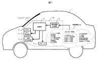
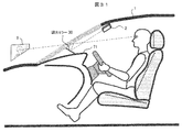
- FIG. 1 is a schematic diagram for explaining the outline of a head up display (hereinafter referred to as HUD) mounted on a vehicle.
- the HUD 100 mounted on the vehicle 1 projects the image light generated by the image display device 2 onto the windshield (hereinafter referred to as a windshield 7) of the vehicle 1 through the mirror 3.
- the image light reflected by the windshield 7 enters the eyes of the driver, and the driver visually recognizes the image from the HUD.
- the video to be displayed includes information related to driving and supports driving operation.
- the HUD 100 includes a vehicle information acquisition unit 5 that acquires various vehicle information 50, a control unit 10 that generates video information to be displayed based on the vehicle information acquisition unit 5, a mirror drive unit 4 that drives the mirror 3, and a driver.
- a speaker 6 for outputting audio information is included.
- the vehicle information 50 includes an operation signal by the driver such as a HUD display On / Off signal and a HUD mirror adjustment signal related to the adjustment of the mirror 3 of the HUD. .
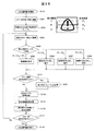
- FIG. 2 is a block diagram showing the internal configuration of the HUD 100.
- Various vehicle information 50 is input to the vehicle information acquisition unit 5 and sent to the control unit 10.
- An electronic control unit (ECU, Electronic Control Unit) 11 in the control unit 10 generates a video signal displayed by the HUD based on the input vehicle information. Moreover, based on vehicle information, the control signal with respect to the mirror 3 and the audio
- the video display device 2 includes a light source 21 such as an LED or a laser, an illumination optical system 22, and a display element 23 such as a liquid crystal element, and emits video light generated by the display element 23 toward the mirror 3.
- an audio output unit 12 that outputs an audio signal to the speaker 6, a non-volatile memory 13 that stores a program executed by the ECU 11, a memory 14 that stores video information and control information, and a light source of the video display device 2 21, a light source adjustment unit 15 that controls 21, a distortion correction unit 16 that corrects distortion of a video signal to be displayed, a display element driving unit 17 that drives the display element 23 based on the corrected video signal, and a mirror driving unit 4.
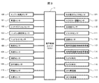
- FIG. 3 is a diagram illustrating an example of a hardware configuration related to the acquisition of the vehicle information 50 in the HUD.
- a part of the hardware configuration of the vehicle information acquisition unit 5 and the control unit 10 will be mainly shown.
- Acquisition of the vehicle information 50 is performed by information acquisition devices, such as various sensors connected to ECU11 under control of ECU11, for example.
- a vehicle speed sensor 101 for example, a vehicle speed sensor 101, a shift position sensor 102, a steering wheel steering angle sensor 103, a headlight sensor 104, an illuminance sensor 105, a chromaticity sensor 106, a distance measuring sensor 107, an infrared sensor 108, an engine start sensor 109, acceleration sensor 110, gyro sensor 111, temperature sensor 112, road-to-vehicle communication wireless receiver 113, vehicle-to-vehicle communication wireless receiver 114, camera (inside the vehicle) 115, camera (outside the vehicle) 116, GPS receiver 117, and VICS (Vehicle Information and Communication System): a device such as a receiver 118, load sensor 119, position sensor 120, HUD display On / Off sensor 121, HUD mirror adjustment sensor 122, etc. Have It is not always necessary to include all these devices, and other types of devices may be included.
- the vehicle information 50 that can be acquired by the equipped device can be used as appropriate.
- the vehicle speed sensor 101 acquires speed information of the vehicle 1.
- the shift position sensor 102 acquires current gear information of the vehicle 1.
- the steering wheel angle sensor 103 acquires steering wheel angle information.
- the headlight sensor 104 acquires lamp lighting information related to On / Off of the headlight.
- the illuminance sensor 105 and the chromaticity sensor 106 acquire external light information.
- the distance measuring sensor 107 acquires distance information between the vehicle 1 and an external object.
- the infrared sensor 108 acquires infrared information related to the presence / absence and distance of an object at a short distance of the vehicle 1.
- the engine start sensor 109 detects engine On / Off information.
- the acceleration sensor 110 and the gyro sensor 111 acquire acceleration gyro information including acceleration and angular velocity as information on the posture and behavior of the vehicle 1.
- the temperature sensor 112 acquires temperature information inside and outside the vehicle.
- the road-to-vehicle communication wireless receiver 113 and the vehicle-to-vehicle communication wireless receiver 114 are respectively road-to-vehicle communication information received by road-to-vehicle communication between the vehicle 1 and roads, signs, signals, etc.
- the vehicle-to-vehicle communication information received by the vehicle-to-vehicle communication with another vehicle is acquired.
- the camera (inside the vehicle) 115 and the camera (outside the vehicle) 116 respectively capture the moving image of the situation inside and outside the vehicle and acquire camera video information (inside / outside the vehicle).
- the camera (inside the vehicle) 115 captures, for example, the driver's posture, eye position, movement, and the like. By analyzing the obtained moving image, for example, it is possible to grasp the driver's fatigue status, the position of the line of sight, and the like.
- the camera (outside the vehicle) 116 captures surrounding conditions such as the front and rear of the vehicle 1. By analyzing the obtained video, for example, it is possible to grasp the presence or absence of moving objects such as other vehicles and people around the building, topography, road surface conditions (rain, snow, freezing, unevenness, etc.) It is.
- the GPS receiver 117 and the VICS receiver 118 obtain GPS information obtained by receiving the GPS signal and VICS information obtained by receiving the VICS signal, respectively. It may be implemented as a part of a car navigation system that acquires and uses these pieces of information.
- the load sensor 119 and the position sensor 120 detect the position / posture of the driver.
- the HUD display On / Off sensor 121 detects whether the HUD power supply is On or Off.
- the HUD mirror adjustment sensor 122 detects an adjustment signal of the HUD mirror and acquires information on whether or not to perform mirror adjustment processing.
- HUD-related sensors may be provided inside the HUD.
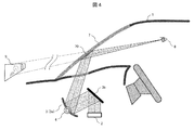
- FIG. 4 is a schematic diagram showing a video display state by HUD.
- Display image light is emitted from the image display device 2 installed at the lower part of the dashboard of the vehicle 1.
- the image light is reflected by the first mirror 3 b and the second mirror 3 a (for example, a concave mirror, a free-form surface mirror, a mirror having an optical axis asymmetric shape, etc.) and projected toward the windshield 7.
- the first mirror 3 b is fixed, and the second mirror 3 a can be rotated by the mirror driving unit 4.
- the second mirror 3a is simply referred to as “mirror 3”.
- the image light converged and projected from the mirror 3 is reflected by the windshield 7, enters the driver's eyes 8, and forms an image on the retina so that the image can be visually recognized.
- the driver sees the virtual image 9 present in front of the windshield 7.
- the reflection position of the image light on the windshield 7 is indicated by reference numeral 70. That is, the driver sees the virtual image 9 in the forward direction of the reflection position 70.
- FIG. 5 is a flowchart showing the basic operation of the HUD.
- (A) shows an initial operation, and (b) shows a normal operation including various adjustments.
- the following processing is controlled by the electronic control unit (ECU) 11 of the control unit 10, and the processing content will be described along the flow.
- ECU electronice control unit
- the vehicle information acquisition unit 5 acquires the vehicle information 50 (S102). First, an appropriate brightness level is calculated from external light information from the illuminance sensor 105 (S103), and the brightness level of the light source 21 is set by controlling the light source adjustment unit 15 (S104). Further, information selected by the driver (for example, current vehicle speed information) is extracted from the acquired vehicle information 50, and an image to be displayed is determined (S105). The distortion correction unit 16 corrects the image distortion generated in the projection optical system (for example, the curved shape of the windshield 7) on the display image (S106).
- the display element drive unit 17 supplies a drive signal to the display element 23 (S107). It is determined whether or not an On signal has been received by the HUD display On / Off sensor 121 (S108) and waits until an On signal is received (S109). When the On signal is received, the light source 21 of the video display device 2 is turned on, and video projection display, that is, normal operation of HUD is started (S110).
- the vehicle information 50 is continuously acquired via the vehicle information acquisition unit 5 (S111). It is determined whether or not a mirror adjustment signal is received from the HUD mirror adjustment sensor 122 (S112), and if received, mirror adjustment processing is performed (S113). In the mirror adjustment processing, the mirror drive unit 4 adjusts the angle of the mirror 3 and the like, which will be described in detail later. Thereafter, a brightness level adjustment process (S114) of the display image and a change process (S115) of the display image are performed, and the display is updated by controlling the display element (S116). The details will be described later.
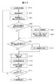
- FIGS. 6A and 6B are flowcharts showing details of the process of FIG. 5, (a) is a mirror adjustment process (S113), (b) is a brightness level adjustment process (S114), and (c) is a display video change process (S115). ).
- the mirror adjustment unit 18 determines the adjustment amount, and the mirror drive unit 4 moves the mirror 3 in order. It is rotated in the direction (or the reverse direction) (S201). It is determined whether or not the mirror adjustment signal is lost (S202), and the rotation is continued during the period of receiving the signal (S203). When the driver stops the operation and the signal disappears, the rotation operation of the mirror 3 is stopped (S204), and the adjustment process is terminated (S205).
- the rotation direction (forward / reverse) of the mirror 3 in S201 can be selected by the driver. Alternatively, the rotation direction (forward / reverse) may be automatically switched when the rotation end is reached. Thus, the driver can adjust the mirror 3 to an optimum angle while viewing the display image of the HUD.
- an appropriate brightness level is calculated from the current external light information by the illuminance sensor 105 (S211). It is determined whether or not the brightness level needs to be changed (S212). If the change is necessary, the light source adjustment unit 15 is controlled to change and set the brightness level of the light source 21 (S213). This completes the adjustment of the brightness level (S214), and the video is displayed at the changed brightness level thereafter.
- the content of the display video is changed based on the latest vehicle information 50 (S221).
- the display speed is changed based on the current speed information from the vehicle speed sensor, or the guidance arrow display is changed based on the navigation information from the GPS receiver or the VICS receiver.
- the item to be displayed can be selected by the driver, and when the item is changed, the content is switched to the content corresponding to the new item. In this way, the display image based on the latest information is determined and supplied to the display element 23 (S222), and the change process is terminated (S223).
- Example 1 describes an example of a mirror adjustment mechanism of a head-up display (HUD) according to the present invention, but will be described in comparison with a conventional adjustment mechanism for easy understanding.
- HUD head-up display
- FIG. 7 is a diagram for explaining a conventional mirror adjustment method 1.
- the video light emitted from the video display device 2 is reflected by the mirror 3, is reflected by the reflection position 70 of the windshield and enters the driver's eyes 8, and the driver visually recognizes it as a virtual image 9.
- the position of the eye 8 (hereinafter referred to as eye point) changes as A, B, C depending on the height of the driver, the image light emitted from the image display device 2 cannot enter each eye point, or Even if it can be incident, a part of the image may be lost.
- the mirror 3 is rotated by the mirror driving unit 4. According to this, the driver can visually recognize the virtual image 9 by adjusting the rotation position of the mirror 3 as A, B, C corresponding to the eye point of the driver.
- the mirror rotation mechanism since only the mirror rotation mechanism is used in this adjustment method 1, the following phenomenon occurs when the driver visually recognizes the display image. (1) Since the reflection position 70 of the windshield moves like A, B, and C, the position where the driver's line of sight intersects the windshield moves. (2) The angle of the line of sight where the driver looks down on the virtual image 9 (hereinafter referred to as the depression angle) changes. (3) The position of the virtual image 9 visually recognized by the driver moves like A, B, and C.
- the above problem is solved as a configuration in which the mirror driving unit 4 includes not only the mirror rotation mechanism but also the mirror movement mechanism. That is, the mirror moving mechanism can easily move the position of the rotation axis of the mirror in the vertical direction and the front-back direction.
- specific adjustment methods 2, 3, and 4 will be described.
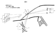
- FIG. 8 is a diagram for explaining the mirror adjustment method 2 according to the present embodiment.
- the problem (1) is addressed, and the reflection position 70 of the windshield is fixed.
- Mirror drive unit 4 can move not only the rotation of mirror 3 but also the rotation axis of the mirror in the vertical direction and the front-rear direction.
- the driver's eye point 8 changes as A, B, C
- the reflection of the windshield is set by combining the rotation and movement of the mirror 3 as shown in FIG.
- the position 70 can be fixed to one position without moving. A specific example of the setting condition will be described later.
- FIG. 9 is a diagram for explaining the mirror adjustment method 3 according to the present embodiment.
- the problem of the above (2) is dealt with and the driver's depression angle is fixed.
- the mirror drive unit 4 moves the mirror 3 to the positions A, B, and C while keeping the rotation angle of the mirror 3 constant as shown in FIG.
- the driver's depression angle ⁇ 1 can be fixed at a constant angle.
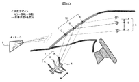
- FIG. 10 is a diagram for explaining the mirror adjustment method 4 according to this embodiment.
- the problem of the above (3) is dealt with, and the position of the virtual image 9 visually recognized by the driver is fixed.
- the driver's visual recognition can be achieved by combining the rotation and movement of the mirror 3 as shown in FIG.
- the position of the virtual image 9 can be fixed. A specific example of the setting condition in this case will also be described later.
- the conventional problems (1), (2), and (3) can be solved by combining the moving mechanism of the mirror 3. Further, the driver can select and implement an appropriate method from the adjustment methods 2 to 4 according to the driving situation and the visibility situation (in that case, the adjustment method 1 may be included as an option).
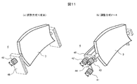
- FIG. 11 is a diagram illustrating an example of an adjustment mechanism of the mirror driving unit 4.
- (A) is the case of the conventional adjustment method 1
- (b) is the case of the adjustment methods 2 to 4 of the present embodiment.
- the mirror driving unit 4 is configured to rotate the mirror 3 by a single rotation motor 40 attached to the fixed arm 49.
- the mirror driving unit 4 rotates and rotates the mirror 3 using the three rotary motors 41, 42, 43 and the two movable arms 44, 45. It is configured to move.
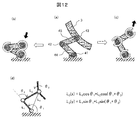
- FIG. 12 is a diagram for explaining the adjustment operation by the adjustment mechanism of FIG.
- the mirror 3 is attached to the rotary motor 43, and the rotary motor 43 is fixed to the housing via a link mechanism including two movable arms 44 and 45 and the rotary motors 41 and 42.
- the height position of the mirror 3 can be lowered as shown in (b) or raised as shown in (c).
- (D) shows the movement position L 3 (x, y) of the mirror 3 by a calculation formula, and the lengths L 1 and L 2 of the movable arms 44 and 45 and the rotation angle ⁇ 1 of the rotary motors 41 and 42, By ⁇ 2 , it can be moved to a desired position.
- the rotation angle of the mirror 3 is given by the rotation angle ⁇ 3 of the rotary motor 43.
- the mirror adjustment mechanism shown here can be realized with a simple structure, the HUD device can be easily mounted on a vehicle without increasing its size.
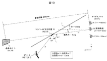
- FIG. 13 is a diagram showing an analysis model of the mirror adjustment mechanism.
- the coordinates (X2, Y2) and the rotation angle ( ⁇ 2) of the mirror 3 are obtained.
- the coordinates (X3, Y3) of the reflection position 70 of the windshield at that time, the center coordinates (X4, Y4) of the virtual image 9 and the depression angle ( ⁇ 1) overlooking the virtual image 9 are calculated.
- the preconditions for the analysis were as follows: the distance to the virtual image 9 was 2000 mm, the inclination angle ⁇ 0 of the windshield 7 was 30 deg, the depression angle ⁇ 1 at the eyepoint reference position (position B) was 8 deg, and the windshield was a flat glass.
- the conditions for the normal viewing of the image at each eye point are that the incident angle ⁇ 1 and the reflection angle ⁇ 2 of the image light at the windshield reflection position 70 are equal and the optical path length r1 + r2 is constant.
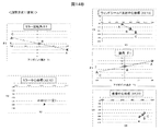
- FIG. 14A and 14B show analysis results in the case of mirror adjustment method 1 (conventional) in FIG.
- the analysis results for each of the eye points A, B, and C are shown as a table in FIG. 14A and as a graph in FIG. 14B.
- the center coordinates (X2, Y2) of the mirror are fixed, and only the rotation angle ( ⁇ 2) of the mirror is changed. Therefore, all of the windshield reflection center coordinates (X3, Y3), the depression angle ( ⁇ 1), and the virtual image center coordinates (X4, Y4) are changed.
- FIG. 15A and 15B show the analysis results in the case of mirror adjustment method 2 (one of the examples) in FIG.
- the analysis results for each of the eye points A, B, and C are shown as a table in FIG. 15A and as a graph in FIG. 15B.
- the center coordinates (X2, Y2) of the mirror and the rotation angle ( ⁇ 2) of the mirror are changed so that the windshield reflection center coordinates (X3, Y3) are constant.
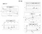
- FIG. 16A and FIG. 16B show the analysis results in the case of the mirror adjustment method 3 (one of the embodiments) of FIG.
- the analysis results for the respective eye points A, B, and C are shown as a table in FIG. 16A and as a graph in FIG. 16B.
- the center coordinates (X2, Y2) of the mirror are changed so that the depression angle ( ⁇ 1) is constant.
- the rotation angle ( ⁇ 2) of the mirror is constant.
- FIG. 17A and FIG. 17B show the analysis results in the case of mirror adjustment method 4 (one of the embodiments) of FIG.
- the analysis results for the respective eye points A, B, and C are represented as a table in FIG. 17A and as a graph in FIG. 17B.
- the mirror center coordinates (X2, Y2) and the mirror rotation angle ( ⁇ 2) are changed so that the virtual image center coordinates (X4, Y4) are constant.
- the mirror adjustment unit 18 stores the adjustment amount of the center coordinates (X2, Y2) and the rotation angle ( ⁇ 2) corresponding to each position of the eye point in each adjustment method in association with each other, and this relationship is stored. Make adjustments while keeping.
- the optimal adjustment amount (coordinates and rotation angle) of the mirror is determined by the driver while viewing the display image. That is, the mirror adjustment unit 18 acquires an operation signal from the driver from the HUD mirror adjustment sensor 122, and determines the end point of the adjustment operation.
- the mirror can be adjusted so that the windshield reflection position and the virtual image position do not move even if the driver's eye position changes, the driver can view the image more preferably without a sense of incongruity. it can. Since the mirror adjustment mechanism used for this can be realized with a simple structure, it can be easily mounted on a vehicle without increasing the size of the apparatus.
- Example 1 the optimum position for mirror adjustment was determined by the driver looking at the video, that is, the manual adjustment method.
- the position of the driver's eyes is calculated, and the mirror position is automatically adjusted to the optimum state accordingly.
- the center of gravity position of the driver is obtained from the driver position and load, and the eye position is calculated from the center of gravity position.
- the mirror adjustment mechanism employs each adjustment method described in the first embodiment, and the mirror driving unit 4 is configured to adjust the coordinate and the rotation angle of the mirror in conjunction with each other.
- FIG. 18 is a diagram showing examples of various sensors in the vehicle used for automatic mirror adjustment.
- load sensors load cell, displacement sensor, etc.
- the position sensor 120 for detecting the position of the driver is provided on a headrest (height position) 120a, a back surface (tilt) 120b, and a seat surface (front-rear position) 120c.
- the center-of-gravity calculation unit 19 in the control unit 10 calculates the driver's driving posture and physique information (height and weight), and derives the driver's center-of-gravity position 65 and the position of the eye point 8.
- the relationship between the center of gravity position 65 and the eye point 8 is estimated based on the physique information.
- the mirror adjusting unit 18 calculates the mirror adjustment amount and optimally adjusts the position and angle of the mirror 3 via the mirror driving unit 4 as described in the first embodiment. Since the mirror adjustment unit 18 stores in advance the optimum adjustment amount (coordinates and rotation angle) of the mirror corresponding to each position of the eye point 8, the mirror can be automatically adjusted to the optimum state. Further, during driving, the driver's center of gravity is monitored, and if the center of gravity shifts, it is determined that the eye point position has also changed, and the mirror is automatically corrected so as to follow this state.
- the shift direction of the center of gravity that is, the shift direction of the eye point can be not only the height direction but also the front-rear direction and the left-right direction as viewed from the driver.
- the mirror can be optimally adjusted with respect to the change in the front-rear direction.
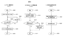
- FIG. 19 is a flowchart showing the automatic mirror adjustment operation. (A) shows initial adjustment, and (b) shows adjustment during operation.
- the detection result is acquired from the load sensor 119 via the vehicle information acquisition unit 5 (S301), and the detection result is acquired from the position sensor 120 (S302).
- the center-of-gravity calculation unit 19 of the control unit 10 calculates the height and weight of the driver from these detection results (S303), and calculates the center-of-gravity position 65 and the eye point 8 position (S304).
- the calculated value is stored as an initial value.
- the mirror adjustment unit 18 calculates a mirror adjustment amount according to the calculated eye point position, and optimally adjusts the position and angle of the mirror 3 via the mirror drive unit 4 (S305). Thereafter, the process proceeds to the HUD normal operation (S306).
- the center of gravity calculation unit 19 monitors the center of gravity position of the driver and monitors the change of the center of gravity position from the initial value (S311).
- the mirror adjustment unit 18 calculates a mirror adjustment amount corresponding to the movement amount ( S314), the position and angle of the mirror 3 are adjusted via the mirror drive unit 4 (S315). If the center of gravity moves in the left-right direction (Yes in S316), the distortion correction unit 16 performs image distortion correction (S317). Thereafter, the flow returns to the center-of-gravity position monitoring (S311) and the above flow is repeated.
- the driver's line-of-sight position is detected by image recognition, but the detection accuracy depends on the surrounding environment, weather, and the like. In particular, under dark conditions during night driving, the detection accuracy is extremely lowered due to a decrease in the amount of light and contrast in the vehicle, and the tracking performance is deteriorated. In general, the line of sight is frequently moved during driving. However, if mirror adjustment is performed by following this movement, the driver may be adversely affected such as eye fatigue or sickness.
- the position of the driver's center of gravity is calculated using a load sensor, a position sensor, etc., and follow-up control is performed according to the movement of the center of gravity. Therefore, the detection value is stable and the display image is stable, so that the driver does not feel uncomfortable.
- the configuration in which the video display area is mainly moved in the vertical direction according to the position (eye point) of the driver has been described.
- a configuration for moving the video display area in the left-right direction will be described.
- Example 3 describes a configuration in which the entire HUD is moved left and right in the dashboard in order to move the video display area in the left and right direction.
- the display area needs to be moved in the left-right direction, for example, in the following cases.
- (1) When the driver's eye position (eye point) moves in the left-right direction.
- (2) When the driver's posture (center of gravity position) moves in the left-right direction.
- (3) When the vehicle traveling direction changes according to the driving operation (the steering wheel operation or the direction indicator).
- the driver's line of sight changes according to road guidance (right / left turn sign or intersection distance).
- (5) When the driver's line of sight changes due to an obstacle (interrupt car or jumping pedestrian).
- the change in the situation is acquired as vehicle information by an information acquisition device (such as various sensors) mounted on the vehicle, and the control unit of the HUD is configured to automatically display an image at an optimal position.
- an information acquisition device such as various sensors
- FIG. 20 is a block diagram showing the internal configuration of the head-up display 100a.
- a function for moving the entire HUD 100a to the left and right is added.
- FIG. 20 in relation to Examples 4 and 5 to be described later, a case where the image display device 2 is installed on the roof of the vehicle for projection, and a dimming mirror 30 capable of switching between reflection / non-reflection as the mirror 3. It includes the case where is used.
- the functions added to the configuration of FIG. 2 are as follows.
- the HUD position adjusting unit 24 determines the moving position of the HUD 100 a and sends a control signal to the HUD driving unit 25.
- the HUD drive unit 25 has a rail guide and a drive motor, as will be described later, and moves the HUD 100a to the left and right.
- the projection angle adjustment unit 26 determines the projection direction (projection angle) when the video display device 2 is installed on the roof of the vehicle, and the projection angle drive unit 27 changes the direction of the projection unit of the video display device 2.
- the dimming mirror control unit 28 When the dimming mirror 30 is used, the dimming mirror control unit 28 generates a reflection / non-reflection switching signal for the dimming mirror 30, and the dimming mirror voltage supply unit 29 applies a predetermined voltage to the dimming mirror 30. Is applied to switch between the mirror surface state (ON state) and the transparent state (OFF state).
- FIG. 21 is a block diagram illustrating an example of a hardware configuration related to the acquisition of the vehicle information 50.
- a direction indicator sensor 123 is added to the configuration of FIG.
- the following sensor is used. (1) Driver's eye position ...
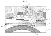
- FIG. 22 is a diagram showing an example of a video display state viewed from the driver's seat.
- An image in this example, a vehicle speed value “60 km / h” is displayed through the windshield 7 so as to overlap the scenery in front.
- This display position (that is, the reflection position 70 on the windshield 7) is moved in the left-right direction in conjunction with the operation of the handle 73, for example.
- the HUD 100 a housed in the lower part of the dashboard 71 is configured to be movable left and right along the driving groove 72.
- FIG. 23 is a cross-sectional view in the vehicle showing the video display operation.
- a groove 72 is formed in the dashboard 71 to accommodate the HUD 100a.
- the HUD 100 a can be moved in the drawing depth direction along the groove 72 by the HUD driving unit 25.
- the image light projected from the HUD 100 a is reflected by the windshield 7 (reflection position 70) and enters the driver's eyes 8, so that the driver sees the virtual image 9 in front of the reflection position 70.
- FIG. 24 is a top view in the vehicle showing the video display operation.
- the HUD driving unit 25 By moving the position of the HUD 100a in the left-right direction by the HUD driving unit 25 (using a driving belt here), the reflection position 70 of the image viewed from the eyes 8 of the driver, that is, the position of the front virtual image 9 is moved. As shown in FIG. 22, the image display position can be moved in the left-right direction.
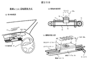
- FIG. 25A and FIG. 25B are diagrams showing a specific drive mechanism of the HUD drive unit 25 in two ways.
- FIG. 25A shows the case of the curved rail drive system, in which (a) is a perspective view inside the vehicle, (b) is a top view of the drive unit, and (c) is an enlarged view of the drive unit.
- the HUD 100a is fixedly mounted on the moving table 79, and the moving table 79 moves in the left-right direction along the curved rail 74 by the driving force of the motor 75 attached to the table.
- the driving force of the motor 75 is transmitted to a directly connected driving roller (driving gear), and the moving table 79 is caused to travel by meshing with the gear of the curved rail 74.
- the projection direction (left-right angle) of the HUD 100a is simultaneously changed according to the curvature, and an image is displayed at an optimum projection angle as seen from the driver seat according to the left-right movement position.
- the type of the motor 75 is not particularly limited, but a stepping motor or a servo motor is suitable.
- FIG. 25B shows the case of the linear rail + rotation drive system, where (a) is a perspective view inside the vehicle, (b) is a side view of the drive unit, and (c) is an enlarged view of the drive unit.
- the HUD 100a is mounted on a moving table 79 via a rotary stage 78.
- the moving table 79 is moved in the left-right direction along a linear guide shaft 77 by a motor 75 and a drive belt 76.
- the moving table 79 is fixed at a predetermined position on the driving belt 76, and the driving belt 76 is between a driving roller (or pulley) for transmitting the driving force of the motor 75 and a driven roller (or pulley) installed on the opposite side.
- Reciprocate at The rotary stage 78 is for changing the projection direction of the HUD 100a, and can thereby display an image with an optimal projection angle in accordance with the horizontal movement position of the HUD 100a.
- the motor 75 is not particularly limited, but a stepping motor or a servo motor is suitable.
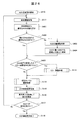
- FIG. 26 is a flowchart showing the display area moving operation by adjusting the HUD position. A process for adjusting the HUD position is added based on the normal operation of the HUD in FIG.
- a case where the display area is moved in conjunction with the handle operation will be described as an example.
- the HUD position adjusting unit 24 calculates an appropriate HUD position according to the steering angle information. For this reason, an appropriate display position (ie, HUD position) with respect to the direction and size of the steering angle is determined in advance. As an example, the amount of movement of the display position in the left-right direction is set to be substantially proportional to the magnitude of the steering angle.
- the HUD position adjustment unit 24 determines whether or not the current HUD position is an appropriate HUD position. If it is an appropriate position, the process proceeds to S405, and if it is different from the appropriate position, the process proceeds to S403 to perform HUD position adjustment processing.
- the HUD drive unit 25 moves the HUD to an appropriate position, and also adjusts the projection direction according to the HUD position.
- the distortion correction setting corresponding to the moved HUD position is updated. In this case, distortion occurs in the video viewed from the driver as the display position moves to the left and right, so the setting of the video correction processing by the distortion correction unit 16 is changed.
- the video display area moves to the left and right according to the position of the driver's eyes and the driving situation.
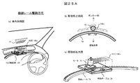
- Example 4 also moves the image display area in the left-right direction, but the image display device with a variable projection direction is installed on the roof inside the vehicle, and the mirror installed on the dashboard is moved left and right.
- FIG. 27 is a diagram showing an example of a video display state viewed from the driver's seat.
- the video display device 2 is installed on the roof and has a configuration in which the projection direction can be changed to the left and right.
- the mirror 3 that receives the image projection light from the image display device 2 is moved by the mirror drive belt 46.
- the moving position of the mirror 3 is linked with the projection direction of the video display device 2. Thereby, the reflection position 70 of an image
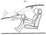
- FIG. 28 is a cross-sectional view in the vehicle showing the video display operation.
- the video display device 2 is installed on the roof, and the projection angle driving unit 27 changes the projection direction.
- the mirror 3 on the dashboard 71 is configured to be moved in the depth direction of the drawing by a mirror driving belt 46 that is one mechanism of the mirror driving unit 4. Thereby, the display position of the virtual image 9 can be moved in the left-right direction.
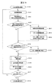
- FIG. 29 is a flowchart showing the display area moving operation by adjusting the projection angle and the mirror position. Steps for adjusting the projection angle and mirror position are added to the normal HUD operation of FIG.
- the case where the display area is moved in conjunction with the handle operation will be described as an example.
- the projection angle adjusting unit 26 calculates an appropriate video projection angle of the video display device 2 according to the steering angle information. Therefore, an appropriate image projection angle with respect to the direction and size of the steering angle is determined in advance.
- the projection angle adjustment unit 26 determines whether or not the current video projection angle is an appropriate video projection angle. If it is an appropriate projection angle, the process proceeds to S416. If it is different from the appropriate projection angle, the process proceeds to S413, and the projection angle and mirror position adjustment processing is performed.
- the video display device 2 installed on the roof is rotated by the projection angle driving unit 27 so that the video projection direction is adjusted to an appropriate projection angle.
- the mirror 3 is moved to a position corresponding to the projection direction by the mirror driving unit 4 (mirror driving belt 46) in accordance with the change of the projection angle.
- the distortion correction setting corresponding to the moved mirror position is updated. In this case, distortion occurs in the video viewed from the driver as the display position moves to the left and right, so the setting of the video correction processing by the distortion correction unit 16 is changed.
- mirror adjustment processing (angle adjustment) is performed in S113. This is because, as the mirror position moves, the relationship between the image projection angle with respect to the windshield 7 and the curvature of the reflecting surface changes, so the elevation angle of the display image viewed from the driver may change. In order to make this elevation angle constant, the angle in the vertical direction of the mirror is adjusted.
- the mirror drive mechanism may be provided with a gradient in the front-rear direction and the gradient may be used to absorb the change in the elevation angle of the display image accompanying the mirror movement. Since S114 and subsequent steps are the same as those in FIG.
- the projection angle adjusting unit 26 first determines the video projection angle of the video display device 2 according to the steering angle, and the mirror driving unit 4 moves the mirror 3 in accordance with the video projection angle.
- the movement position of the mirror 3 may be determined first by the mirror adjustment unit 4 according to the steering angle, and the projection angle driving unit 27 may change the image projection angle accordingly.
- the change of the steering angle of the steering wheel has been described as an example of moving the image display area in the left-right direction, but it goes without saying that the present invention can be similarly applied to any change in the states (1) to (5). .
- the configuration becomes simple and the moving speed of the display position is improved.
- Example 5 also moves the video display area in the left-right direction, but a video display device with a wide viewing angle is installed on the roof inside the vehicle, and a plurality of dimming mirrors are arranged on the dashboard in the left-right direction, It was set as the structure which switches the reflection / non-reflection state of each light control mirror.
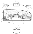
- FIG. 30 is a diagram illustrating an example of a video display state viewed from the driver's seat.
- the video display device 2 having a wide viewing angle is installed on the roof, and a plurality of light control mirrors 30 are arranged on the dashboard 71 in the left-right direction. Since the video display device 2 has display characteristics with a wide viewing angle, it is possible to irradiate the video mirrors 30 with video light simultaneously.
- an image is displayed at the position of the dimming mirror 30 in the reflective state (ON state), but no image is displayed at the position of the dimming mirror 30 in the non-reflecting state (OFF state).
- the dimming mirror 30 By selecting the dimming mirror 30 to be in the reflection state (ON state), the image reflection position 70 can be moved in the left-right direction.
- FIG. 31 is a cross-sectional view in the vehicle showing the video display operation.
- the wide viewing angle video display device 2 is installed on the roof, and a plurality of light control mirrors 30 are arranged on the dashboard 71 in the depth direction of the drawing.
- the dimming mirror control unit 28 moves the display position of the virtual image 9 in the left-right direction by selecting the dimming mirror 30 to be reflected (ON state) and applying a predetermined voltage by the dimming mirror voltage supply unit 29. Can be made.
- FIG. 32 is a flowchart showing a display area moving operation by switching the reflection / non-reflection state of the light control mirror. A step for switching the dimming mirror is added to the normal operation of the HUD in FIG.
- the case where the display area is moved in conjunction with the handle operation will be described as an example.
- the dimming mirror control unit 28 calculates an appropriate video display area corresponding to the steering angle information. Therefore, an appropriate video display area for the direction and size of the steering angle is determined in advance.
- the dimming mirror control unit 28 determines whether or not the current video display area (the position of the dimming mirror in the ON state) is an appropriate display area. If it is an appropriate display area, the process proceeds to S425, and if it is different from the appropriate display area, the process proceeds to S423 to perform switching processing of the light control mirror 30.
- the dimming mirror voltage supply unit 29 applies a predetermined voltage to the dimming mirror 30 corresponding to the appropriate display area to switch to the reflection state (ON state), and other dimming
- the mirror 30 is switched to a non-reflective state (OFF state).
- the distortion correction setting corresponding to the dimming mirror switched to the ON state is updated. In this case, distortion occurs in the video viewed from the driver as the display position moves to the left and right, so the setting of the video correction processing by the distortion correction unit 16 is changed.
- mirror adjustment processing (angle adjustment) is performed in S113. This is because the relationship between the image projection angle with respect to the windshield 7 and the curvature of the reflecting surface changes as the dimming mirror position in the ON state moves, so that the elevation angle of the display image viewed from the driver changes. There is. In order to make this elevation angle constant, the angle in the vertical direction of the dimming mirror is adjusted. When arranging the plurality of dimming mirrors 30, a change in the elevation angle of the display image associated with mirror switching may be absorbed by providing a gradient in the front-rear direction according to the position of each mirror. Since S114 and subsequent steps are the same as those in FIG.
- the change of the steering angle of the steering wheel has been described as an example of moving the image display area in the left-right direction, but it goes without saying that the present invention can be similarly applied to any change in the states (1) to (5). .
- the HUD configuration becomes simpler and the display position can be switched at high speed.
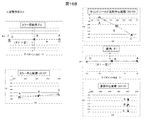
- Example 6 describes a configuration for expanding a display area.
- the size of the area in which video can be displayed by one HUD is limited by the size of the mirror.
- the display area is enlarged by displaying an image while moving the mirror at high speed.
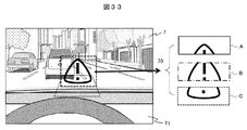
- FIG. 33 is a diagram illustrating an example of a video display state viewed from the driver's seat.
- Video light is emitted from the HUD installed at the lower part of the dashboard 71 and displayed at the reflection position 70 of the windshield 7.
- a plurality of partial images A, B, and C are alternately displayed while being shifted in the vertical direction at the reflection position 70, so that the display area is expanded as compared with the case where a single image (for example, only the image B) is displayed. be able to.
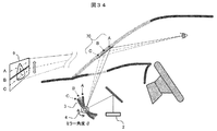
- FIG. 34 is a cross-sectional view in the vehicle showing the video display operation.
- the image light emitted from the image display device 2 is reflected at the reflection position 70 of the mirror 3 and the windshield, and the driver visually recognizes the image as a virtual image 9.
- the mirror driving unit 4 displays the mirror 3 while rotating the mirror 3 by a predetermined angle ⁇ , whereby the reflection position 70 and the display position of the virtual image 9 can be shifted up and down like A, B, and C.
- the corresponding partial images A, B, and C shown in FIG. 33 are displayed in synchronization with the rotation position of the mirror (that is, the display positions A, B, and C).
- the rotational position of the mirror may be controlled in synchronization with the timing of generating the partial images A, B, and C.
- the partial images A, B, and C can be generated by changing the vertical cutout position (drawing start position) with respect to the entire image.
- Mirror movement by the mirror drive unit 4 may be reciprocation between A and C or rotational movement in one direction, but in the case of a moving image, it is moved at high speed so as to follow the changing speed. Further, when the movement of the mirror is a continuous movement, the effective display time (duty ratio) is shortened because the image is displayed only at the timing when the rotation position of the mirror coincides with the display position of each partial image. Therefore, in order to lengthen the effective display time, the movement of the mirror is preferably intermittent movement (step feed) instead of continuous movement.
- FIG. 35 is a flowchart showing an enlarged image display operation by mirror movement. A process of mirror movement and display image switching is added to the HUD normal operation of FIG.
- the mirror driving unit 4 starts reciprocating (or rotating) movement of the mirror 3.
- the mirror motion is a continuous motion.
- the display element driving unit 17 determines a division specification (for example, division into partial images A, B, and C) of the display image, and the mirror adjustment unit 18 uses a mirror angle for displaying the partial images A, B, and C.
- ⁇ A , ⁇ B , and ⁇ C are set and stored in the memory 14.
- the current mirror angle ⁇ is acquired from the mirror driving unit 4, and in S504, the mirror adjusting unit 18 compares the current mirror angle ⁇ with the display angles ⁇ A , ⁇ B , and ⁇ C. If the current mirror angle ⁇ is different from any of the display angles ⁇ A , ⁇ B , and ⁇ C as a result of the comparison, the process proceeds to S505, and the display element driving unit 17 outputs a black image to the video display device 2.
- the light source 21 may be turned off by the light source adjustment unit 15.
- the process proceeds to S506, where the display element driving unit 17 cuts out the partial image A, outputs it to the video display device 2, and displays it.
- the process proceeds to S507, the display is cut out partial image B. If the current mirror angle ⁇ matches the display angle ⁇ C , the process proceeds to S508, where the partial image C is cut out and displayed.
- the partial images A, B, and C can be alternately displayed, and as a result, the entire image can be displayed. According to the present embodiment, it is possible to display a large screen image by enlarging the display area of the image while using one HUD.
- the present invention is not limited to the above-described embodiments, and includes various modifications.
- a part of the configuration of one embodiment can be replaced with the configuration of another embodiment, and the configuration of another embodiment can be added to the configuration of one embodiment.
Landscapes
- Engineering & Computer Science (AREA)
- Physics & Mathematics (AREA)
- General Physics & Mathematics (AREA)
- Computer Hardware Design (AREA)
- Theoretical Computer Science (AREA)
- Optics & Photonics (AREA)
- Chemical & Material Sciences (AREA)
- Combustion & Propulsion (AREA)
- Transportation (AREA)
- Mechanical Engineering (AREA)
- Instrument Panels (AREA)
Abstract
運転者の目の位置が変化しても、簡単な構造でより好適に映像を視認できる車両用映像表示装置を提供する。車両用映像表示装置100は、光源と表示素子を有し映像光を出射する映像表示部2と、映像表示部2から出射された映像光をウィンドシールド7に向けて反射させるミラー3と、ミラー3の角度と位置を変化させるミラー駆動部4と、ミラーの角度と位置の変化量を決定してミラー駆動部4を制御する制御部10と、を備える。制御部10は、運転者の目8の位置が変化しても映像を視認できるとともに、運転者に対する映像の表示状態が変化しないようにミラーの角度と位置の変化量を連動させて決定する。
Description
本発明は、車両等に搭載し各種映像情報を表示するのに好適な車両用映像表示装置に関するものである。
近年、映像を現実空間に重ねて表示する技術の1つとして、車両のフロントガラス(ウィンドシールドともいう)に各種情報を表示する車両用映像表示装置(いわゆるヘッドアップディスプレイ(以下、HUD))が実用化されている。例えば表示する映像情報として運転者向けの情報を提供することで、車両の運転操作を支援することができる。
HUDの基本構成は、光学的に生成した映像をフロントガラスに投射し、反射した映像光が運転者の目に入射し、運転者はその虚像をフロントガラスの前方に視認するものである。その際、運転者の目の位置(アイポイント)によって、映像(虚像)の見え方が異なってくる。すなわち、HUDから投射する映像光の方向と、運転者の目の位置とが一致しないと、運転者は映像を正常に視認できないことになる。
そこで、運転者の目の位置に合わせて投射方向を調整するために、HUDには、生成した映像光をフロントガラスに向けて反射させるミラー(凹面鏡)と、ミラーの角度を変えるミラー駆動機構が備えられている(例えば特許文献1参照)。
特許文献1を始め従来のHUDでは、ミラーの角度を変えるミラー駆動機構を備えているが、ミラーを回転させる機能のみとなっていた。そのため運転者は、目の高さに応じてミラーの角度を調整して映像(虚像)を視認できるように設定することはできるが、映像の見え方が変化してしまう。例えば、フロントガラス面の反射位置や虚像の結像する位置が移動してしまい、運転に必要な前方の視野の一部を遮る恐れがある。あるいは映像を見下ろす角度(俯角)が変化して、運転者に違和感を与えることがある。
また、映像の表示位置を、運転者の目の位置だけでなく運転操作や道路状況に応じて移動させたい場合がある。そのための表示位置移動機能についても簡単な構造にて実現することが求められる。
本発明の目的は、運転者の目の位置が変化しても、簡単な構造でより好適に映像を視認できる車両用映像表示装置を提供することである。
本発明は上記課題を解決するため、車両に搭載し、ウィンドシールドに映像光を投射して該ウィンドシールドの前方に虚像を結像させることで運転者に対して映像を表示する車両用映像表示装置において、光源と表示素子を有し前記映像光を出射する映像表示部と、前記映像表示部から出射された前記映像光を前記ウィンドシールドに向けて反射させるミラーと、前記ミラーの角度と位置を変化させるミラー駆動部と、前記ミラーの角度と位置の変化量を決定して前記ミラー駆動部を制御する制御部と、を備え、前記制御部は、前記運転者の目の位置が変化しても前記虚像を視認できるとともに、前記運転者に対する映像の表示状態が変化しないように前記ミラーの角度と位置の変化量を連動させて決定する。
好ましくは前記ミラー駆動部は、前記ミラーを回転させる回転モータを含む3個の回転モータと、各回転モータを連結する2個の可動アームからなるリンク機構で構成する。
本発明によれば、運転者の目の位置が変化しても、簡単な構造でより好適に映像を視認できる車両用映像表示装置を提供することができる。
始めに、車両用映像表示装置の基本構成について説明する。
図1は、車両に搭載したヘッドアップディスプレイ(Head Up Display以下、HUD)の概要を説明する模式図である。車両1に搭載されたHUD100は、映像表示装置2で生成した映像光をミラー3を介して車両1のフロントガラス(以下、ウィンドシールド7と呼ぶ)に投射する。ウィンドシールド7で反射した映像光は運転者の目に入射し、運転者はHUDからの映像を視認する。表示する映像には運転に関連する情報が含まれ、運転操作を支援するものとなる。HUD100の内部は、各種の車両情報50を取得する車両情報取得部5と、これをもとに表示する映像情報を生成する制御部10と、ミラー3を駆動するミラー駆動部4、運転者に音声情報を出力するスピーカ6などを有する。車両情報50には車両の運転状態を示す速度情報やギア情報などの他に、HUDのミラー3の調整に関連するHUD表示On/Off信号やHUDミラー調整信号などの運転者による操作信号を含む。
図1は、車両に搭載したヘッドアップディスプレイ(Head Up Display以下、HUD)の概要を説明する模式図である。車両1に搭載されたHUD100は、映像表示装置2で生成した映像光をミラー3を介して車両1のフロントガラス(以下、ウィンドシールド7と呼ぶ)に投射する。ウィンドシールド7で反射した映像光は運転者の目に入射し、運転者はHUDからの映像を視認する。表示する映像には運転に関連する情報が含まれ、運転操作を支援するものとなる。HUD100の内部は、各種の車両情報50を取得する車両情報取得部5と、これをもとに表示する映像情報を生成する制御部10と、ミラー3を駆動するミラー駆動部4、運転者に音声情報を出力するスピーカ6などを有する。車両情報50には車両の運転状態を示す速度情報やギア情報などの他に、HUDのミラー3の調整に関連するHUD表示On/Off信号やHUDミラー調整信号などの運転者による操作信号を含む。
図2は、HUD100の内部構成を示すブロック図である。車両情報取得部5には各種の車両情報50が入力され制御部10へ送られる。制御部10内の電子制御ユニット(ECU、Electronic Control Unit)11は、入力した車両情報に基づきHUDが表示する映像信号を生成する。また、車両情報に基づき、ミラー3に対する制御信号やスピーカ6の音声信号を生成する。映像表示装置2は、LEDやレーザなどの光源21、照明光学系22、液晶素子などの表示素子23からなり、表示素子23で生成された映像光をミラー3に向けて出射する。
制御部10内には、スピーカ6に音声信号を出力する音声出力部12、ECU11が実行するプログラムを格納する不揮発性メモリ13、映像情報や制御情報を記憶するメモリ14、映像表示装置2の光源21を制御する光源調整部15、表示する映像信号の歪みを補正する歪み補正部16、補正された映像信号に基づき表示素子23を駆動する表示素子駆動部17、ミラー駆動部4に対して駆動信号を出力するミラー調整部18、運転者の重心位置を算出する重心算出部19などを有する。
図3は、HUDにおける車両情報50の取得に係るハードウェア構成の例を示す図である。ここでは主に車両情報取得部5および制御部10の一部のハードウェア構成について示す。車両情報50の取得は、例えば、ECU11の制御の下、ECU11に接続された各種のセンサ等の情報取得デバイスにより行われる。
これらの情報取得デバイスとして、例えば、車速センサ101、シフトポジションセンサ102、ハンドル操舵角センサ103、ヘッドライトセンサ104、照度センサ105、色度センサ106、測距センサ107、赤外線センサ108、エンジン始動センサ109、加速度センサ110、ジャイロセンサ111、温度センサ112、路車間通信用無線受信機113、車車間通信用無線受信機114、カメラ(車内)115、カメラ(車外)116、GPS受信機117、およびVICS(Vehicle Information and Communication System:道路交通情報通信システム、登録商標(以下同様))受信機118、荷重センサ119、位置センサ120、HUD表示On/Offセンサ121、HUDミラー調整センサ122などの各デバイスを有する。必ずしもこれら全てのデバイスを備えている必要はなく、また、他の種類のデバイスを備えていてもよい。備えているデバイスによって取得できる車両情報50を適宜用いることができる。
車速センサ101は、車両1の速度情報を取得する。シフトポジションセンサ102は、車両1の現在のギア情報を取得する。ハンドル操舵角センサ103は、ハンドル操舵角情報を取得する。ヘッドライトセンサ104は、ヘッドライトのOn/Offに係るランプ点灯情報を取得する。照度センサ105および色度センサ106は、外光情報を取得する。測距センサ107は、車両1と外部の物体との間の距離情報を取得する。赤外線センサ108は、車両1の近距離における物体の有無や距離等に係る赤外線情報を取得する。エンジン始動センサ109は、エンジンOn/Off情報を検知する。
加速度センサ110およびジャイロセンサ111は、車両1の姿勢や挙動の情報として、加速度や角速度からなる加速度ジャイロ情報を取得する。温度センサ112は車内外の温度情報を取得する。路車間通信用無線受信機113および車車間通信用無線受信機114は、それぞれ、車両1と道路や標識、信号等との間の路車間通信により受信した路車間通信情報、および車両1と周辺の他の車両との間の車車間通信により受信した車車間通信情報を取得する。
カメラ(車内)115およびカメラ(車外)116は、それぞれ、車内および車外の状況の動画像を撮影してカメラ映像情報(車内/車外)を取得する。カメラ(車内)115では、例えば、運転者の姿勢や、目の位置、動き等を撮影する。得られた動画像を解析することにより、例えば、運転者の疲労状況や視線の位置などを把握することが可能である。また、カメラ(車外)116では、車両1の前方や後方等の周囲の状況を撮影する。得られた動画像を解析することにより、例えば、周辺の他の車両や人等の移動物の有無、建物や地形、路面状況(雨や積雪、凍結、凹凸等)などを把握することが可能である。
GPS受信機117およびVICS受信機118は、それぞれ、GPS信号を受信して得られるGPS情報およびVICS信号を受信して得られるVICS情報を取得する。これらの情報を取得して利用するカーナビゲーションシステムの一部として実装されていてもよい。
荷重センサ119および位置センサ120は、運転者の位置・姿勢を検出する。HUD表示On/Offセンサ121は、HUDの電源がOnかOffかの状態を検出する。HUDミラー調整センサ122は、HUDミラーの調整信号を検出し、ミラー調整処理を実施するか否かの情報を取得する。
なお、各種センサはHUDの外部に存在するものとしたが、HUD関連のセンサ(121,122等)はHUDの内部に備えていてもよい。
図4は、HUDによる映像表示状態を示す模式図である。車両1のダッシュボードの下部に設置された映像表示装置2から、表示用の映像光が出射される。映像光は、第1のミラー3bと第2のミラー3a(例えば、凹面ミラーや自由曲面ミラー、光軸非対称の形状を有するミラー等)で反射され、ウィンドシールド7に向けて投射される。第1のミラー3bは固定されており、第2のミラー3aはミラー駆動部4により回転可能となっている。以下の説明では、第2のミラー3aを単に「ミラー3」と呼ぶことにする。
ミラー3から収束して投射された映像光は、ウィンドシールド7にて反射され運転者の目8に入射して網膜上に結像することで、映像を視認することができる。そのとき運転者は、ウィンドシールド7の前方に存在する虚像9を見ていることになる。ウィンドシールド7における映像光の反射位置を符号70で示す。すなわち運転者は、反射位置70の前方方向に虚像9を見ることになる。
図5は、HUDの基本動作を示すフローチャートである。(a)は初期動作を、(b)は各種調整を含む通常動作を示す。以下の処理は制御部10の電子制御ユニット(ECU)11により制御され、フローに沿って処理内容を説明する。
(a)の初期動作(S100)において、エンジン始動センサ109により電源(イグニッション)Onの信号を受けると(S101)、車両情報取得部5により車両情報50を取得する(S102)。まず、照度センサ105による外光情報から、適切な明るさレベルを算出し(S103)、光源調整部15を制御して光源21の明るさレベルを設定する(S104)。また、取得した車両情報50から運転者が選択した情報(例えば、現在の車速情報)を抽出して、表示する映像を決定する(S105)。表示映像に対し、歪み補正部16により投射光学系(例えばウィンドシールド7の曲面形状)で生じる映像歪みの補正を実施する(S106)。表示素子駆動部17により、表示素子23に対して駆動信号を供給する(S107)。HUD表示On/Offセンサ121によりOn信号を受けたか否かを判定し(S108)、On信号を受けるまで待機する(S109)。On信号を受けると映像表示装置2の光源21を点灯させ、映像の投射表示すなわちHUDの通常動作を開始する(S110)。
(b)の通常動作(S110)では、引き続き車両情報取得部5を介して車両情報50を取得する(S111)。HUDミラー調整センサ122からのミラー調整信号を受けたか否かを判定し(S112)、受けた場合にはミラー調整処理を実施する(S113)。ミラー調整処理ではミラー駆動部4によりミラー3の角度等を調整するが、詳細は後述する。その後、表示映像の明るさレベル調整処理(S114)と、表示映像の変更処理(S115)を実施し、表示素子を制御して表示を更新する(S116)が、詳細は後述する。HUD表示On/Offセンサ121によりOff信号を受けたか否かを判定し(S117)、Off信号を受けるまでS111からの処理を繰り返す。Off信号を受けると映像表示装置2の光源21を消灯し、映像の投射表示を終了する(S118)。
図6は、図5の処理の詳細を示すフローチャートであり、(a)はミラー調整処理(S113)、(b)は明るさレベル調整処理(S114)、(c)は表示映像変更処理(S115)について示す。
(a)のミラー調整処理(S200)では、運転者の操作によりHUDミラー調整センサ122からミラー調整信号を受けると、ミラー調整部18が調整量を決定し、ミラー駆動部4はミラー3を順方向(又は逆方向)に回転させる(S201)。ミラー調整信号がなくなったか否かを判定し(S202)、信号を受けている期間は回転を続ける(S203)。運転者が操作を中止して信号がなくなると、ミラー3の回転動作を停止させて(S204)、調整処理を終了する(S205)。S201におけるミラー3の回転方向(順/逆)は運転者が選択可能とするが、あるいは回転終端に達すると自動的に回転方向(順/逆)が切り替わるようにしてもよい。これにより、運転者はHUDの表示映像を見ながらミラー3を最適の角度に調整することができる。
(b)の明るさレベル調整処理(S210)では、照度センサ105による現在の外光情報から、適切な明るさレベルを算出する(S211)。明るさレベルの変更が必要か否かを判定し(S212)、変更が必要な場合には光源調整部15を制御して光源21の明るさレベルを変更して設定する(S213)。これで明るさレベルの調整を終了し(S214)、以後、変更された明るさレベルで映像の表示が行われる。
(c)の表示映像変更処理(S220)では、最新の車両情報50をもとに表示映像の内容を変更する(S221)。例えば、車速センサからの現在の速度情報をもとに表示速度を変更したり、GPS受信機やVICS受信機からのナビゲーション情報をもとに案内矢印表示を変更する。もちろん、表示する項目は運転者が選択可能であり、項目が変更された場合には新たな項目に対応する内容に切り替える。このようにして最新情報に基づく表示映像を決定して表示素子23に供給し(S222)、変更処理を終了する(S223)。
以上が車両用映像表示装置(ヘッドアップディスプレイ)の基本構成と基本動作である。次に、本発明において運転者の目の位置に合わせてミラーの回転や位置を好適に調整する機構について、実施例で説明する。
実施例1では本発明によるヘッドアップディスプレイ(HUD)のミラー調整機構の例を説明するが、理解を容易にするため従来の調整機構と比較して説明する。
図7は、従来のミラー調整方式1を説明する図である。映像表示装置2から出射された映像光は、ミラー3で反射され、ウィンドシールドの反射位置70で反射されて運転者の目8に入射し、運転者は虚像9として視認する。運転者の身長により目8の位置(以下、アイポイントと呼ぶ)がA,B,Cのように変化すると、映像表示装置2から出射された映像光がそれぞれのアイポイントに入射できない場合、あるいは入射できても映像の一部が欠落する場合ある。これに対応するため従来の調整方式1では、ミラー駆動部4によりミラー3を軸回転させる機構としていた。これによれば、運転者のアイポイントに対応してミラー3の回転位置をA,B,Cのように調整することで、運転者は虚像9を視認することができる。
しかしながらこの調整方式1ではミラーの回転機構のみとしているので、運転者が表示映像を視認するとき以下の現象が伴い課題となる。
(1)ウィンドシールドの反射位置70がA,B,Cのように移動するので、運転者の視線がウィンドシールドと交差する位置が移動する。
(2)運転者が虚像9を見下ろす視線の角度(以下、俯角と呼ぶ)が変化する。
(3)運転者が視認する虚像9の位置がA,B,Cのように移動する。
(1)ウィンドシールドの反射位置70がA,B,Cのように移動するので、運転者の視線がウィンドシールドと交差する位置が移動する。
(2)運転者が虚像9を見下ろす視線の角度(以下、俯角と呼ぶ)が変化する。
(3)運転者が視認する虚像9の位置がA,B,Cのように移動する。
これらの移動(変化)はいずれも運転者に対して違和感を与えることになる。(1)~(3)の変化が大きい場合には、運転に必要なウィンドシールドの前方の視野の一部を遮る恐れが生じるので好ましくない。なお、運転者のアイポイントに合わせてHUD全体、あるいは投射光学系全体を上下に調整する機構も可能であるが、移動機構が大型化するという欠点がある。
そこで本実施例では、ミラー駆動部4においてミラーの回転機構だけでなくミラーの移動機構も備える構成として、上記の課題を解決する。すなわち、ミラー移動機構により、ミラーの回転軸の位置を上下方向と前後方向に容易に移動できるようにした。以下、具体的な調整方式2,3,4について説明する。
図8は、本実施例によるミラー調整方式2を説明する図である。調整方式2では、上記(1)の課題に対処し、ウィンドシールドの反射位置70を固定させるようにした。
ミラー駆動部4はミラー3の回転だけでなく、ミラー回転軸を上下方向と前後方向に移動可能としている。運転者のアイポイント8がA,B,Cのように変化した場合、図8のようにミラー3の回転と移動を組み合わせてA,B,Cの状態に設定することで、ウィンドシールドの反射位置70は移動せず1つの位置に固定することができる。なお、設定条件の具体例は後述する。
図9は、本実施例によるミラー調整方式3を説明する図である。調整方式3では、上記(2)の課題に対処し、運転者の俯角を固定させるようにした。
運転者のアイポイント8がA,B,Cのように変化した場合、ミラー駆動部4は図9のようにミラー3の回転角を一定にしたままA,B,Cの位置に移動させることで、運転者の俯角θ1を一定の角度に固定することができる。この場合の設定条件の具体例も後述する。
図10は、本実施例によるミラー調整方式4を説明する図である。調整方式4では、上記(3)の課題に対処し、運転者が視認する虚像9の位置を固定するようにした。
運転者のアイポイント8がA,B,Cのように変化した場合、図10のようにミラー3の回転と移動を組み合わせてA,B,Cの状態に設定することで、運転者の視認する虚像9の位置を固定することができる。この場合の設定条件の具体例も後述する。
このように、調整方式2~4によればミラー3の移動機構を組み合わせることで、従来の課題(1)(2)(3)をそれぞれ解決することができる。また運転者は、運転状況や視界状況に応じて、調整方式2~4から適切な方式を選択して実施させることができる(その際、調整方式1を選択肢に含めてもよい)。
図11は、ミラー駆動部4の調整機構の例を示す図である。(a)は従来の調整方式1の場合、(b)は本実施例の調整方式2~4の場合である。
(a)の従来の調整機構では、ミラー駆動部4は、固定アーム49に取り付けた単一の回転モータ40でミラー3を回転させる構成であった。これに対し(b)の本実施例の調整機構では、ミラー駆動部4は、3個の回転モータ41,42,43と2個の可動アーム44,45とを用いて、ミラー3を回転及び移動させる構成としている。
図12は、図11(b)の調整機構による調整動作を説明する図である。(a)のようにミラー3を回転モータ43に取り付け、回転モータ43は2つの可動アーム44,45と回転モータ41,42からなるリンク機構を介して筐体に固定する。各回転モータを所定方向に回転させることで、ミラー3の高さ位置を(b)のように下降させたり、(c)のように上昇させたりすることができる。(d)はミラー3の移動位置L3(x、y)を計算式で示したもので、可動アーム44,45の長さL1,L2と回転モータ41,42の回転角θ1、θ2により、所望の位置に移動させることができる。当然ながら、ミラー3の回転角は回転モータ43の回転角θ3で与えられる。
ここに示したミラー調整機構は簡単な構造で実現できるので、HUD装置が大型化することなく車両に容易に搭載することができる。
以下、上記各調整方式1~4において、アイポイントの位置の変化に追従するためのミラー3の調整量(位置と回転角)の解析結果を示す。
図13は、ミラー調整機構の解析モデルを示す図である。解析では、アイポイント8の座標を(X1,Y1)とし、高さ方向にA(Y1=+100mm),B(Y1=0mm),C(Y1=-100mm)と変化するとき、これに追従するためのミラー3の座標(X2,Y2)と回転角(θ2)を求める。さらに、そのときのウィンドシールドの反射位置70の座標(X3,Y3)、虚像9の中心座標(X4,Y4)、虚像9を見下ろす俯角(θ1)の変化を算出する。
解析の前提条件は、虚像9までの距離を2000mm、ウィンドシールド7の傾斜角θ0を30deg、アイポイントの基準位置(B位置)における俯角θ1を8deg、ウィンドシールドを平面ガラスと仮定した。各アイポイントにおいて映像が正常に視認できるための条件は、ウィンドシールド反射位置70における映像光の入射角α1と反射角α2が等しいこと、光路長r1+r2が一定となることである。
図14Aと図14Bは、図7のミラー調整方式1(従来)の場合の解析結果を示す。各アイポイントA,B,Cに対する解析結果を、図14Aでは表で表し、図14Bではグラフで表している。調整方式1では、ミラーの中心座標(X2,Y2)を固定し、ミラーの回転角(θ2)のみを変えている。そのため、ウィンドシールド反射中心座標(X3,Y3)、俯角(θ1)、虚像中心座標(X4,Y4)のいずれも変化している。
図15Aと図15Bは、図8のミラー調整方式2(実施例の1つ)の場合の解析結果を示す。各アイポイントA,B,Cに対する解析結果を、図15Aでは表で表し、図15Bではグラフで表している。調整方式2では、ウィンドシールド反射中心座標(X3,Y3)が一定となるように、ミラーの中心座標(X2,Y2)と、ミラーの回転角(θ2)を変えている。
図16Aと図16Bは、図9のミラー調整方式3(実施例の1つ)の場合の解析結果を示す。各アイポイントA,B,Cに対する解析結果を、図16Aでは表で表し、図16Bではグラフで表している。調整方式3では、俯角(θ1)が一定となるように、ミラーの中心座標(X2,Y2)を変えている。この方式では、ミラーの回転角(θ2)は一定とする。
図17Aと図17Bは、図10のミラー調整方式4(実施例の1つ)の場合の解析結果を示す。各アイポイントA,B,Cに対する解析結果を、図17Aでは表で表し、図17Bではグラフで表している。調整方式4では、虚像中心座標(X4,Y4)が一定となるように、ミラーの中心座標(X2,Y2)と、ミラーの回転角(θ2)を変えている。
このように、アイポイントの変化に追従するためのミラーの中心座標(X2,Y2)と回転角(θ2)の調整量は、各調整方式2-4において異なり、また中心座標(X2,Y2)と回転角(θ2)の値を連動させて変化させる必要がある。よって、ミラー調整部18では、各調整方式における、アイポイントの各位置に対応するミラーの中心座標(X2,Y2)と回転角(θ2)の調整量を関連付けて記憶しておき、この関係を保ちつつ調整を行うようにする。なお、ミラーの最適調整量(座標と回転角)は運転者が表示映像を見ながら決定するものとする。すなわちミラー調整部18は、運転者からの操作信号をHUDミラー調整センサ122から取得し、調整動作の終了点を判断する。
なお、上記の各解析では、アイポイントが高さ方向(Y方向)に変化する場合を説明したが、アイポイントが前後方向(X方向)に変化する場合にも、図13に述べた解析手法を適用することで、各調整方式2-4と同様のミラー調整を行うことができる。
実施例1によれば、運転者の目の位置が変化してもウィンドシールド反射位置や虚像位置が移動しないようにミラーの調整ができるので、運転者は映像をより好適に違和感なく見ることができる。これに用いるミラー調整機構は簡単な構造で実現できるので、装置が大型化することなく車両に容易に搭載することができる。
実施例1では、ミラー調整における最適位置は運転者が映像を見て決定する構成、すなわち手動調整方式であった。これに対し実施例2では、運転者の目の位置を算出し、これに応じてミラーの位置を最適状態に自動的に調整する方式とする。運転者の目の位置を検出するため、本実施例では、運転者の位置や荷重から運転者の重心位置を求め、重心位置から目の位置を算出するようにした。
これにより、運転者が他の運転者に交代したとき、あるいは同一の運転者でもその運転姿勢が変化したとき、そのときの運転者の目の位置に追従して最も見やすい映像表示を行うことができる。なお、ミラーの調整機構は実施例1で述べた各調整方式を採用し、ミラー駆動部4では、ミラーの座標と回転角を連動させて調整する構成としている。
図18は、ミラー自動調整のために使用する車両内各種センサの例を示す図である。運転者の荷重を検出する荷重センサ(ロードセル、変位センサなど)119として、運転席のヘッドレスト119a、背面119b、座面119cにそれぞれ設ける。また、運転者の位置を検出する位置センサ120として、ヘッドレスト(高さ位置)120a、背面(傾き)120b、座面(前後位置)120cに設ける。これらにより、制御部10内の重心算出部19は、運転者の運転姿勢と体格情報(身長、体重)を算出し、運転者の重心位置65およびアイポイント8の位置を導出する。ここで、重心位置65とアイポイント8の関係は、体格情報をもとに推定する。
アイポイント8の位置が分かれば、実施例1で述べたように、ミラー調整部18はミラー調整量を算出し、ミラー駆動部4を介してミラー3の位置や角度を最適に調整する。ミラー調整部18はアイポイント8の各位置に対応するミラーの最適調整量(座標と回転角)を予め記憶しているので、ミラーを最適状態に自動的に調整することができる。さらに運転中には運転者の重心位置をモニタリングし、重心位置がずれた場合にはアイポイント位置も変化したと判断し、これに追従してミラーを最適状態となるよう自動的に修正する。
重心位置のずれ方向、すなわちアイポイントのずれ方向は、高さ方向だけでなく運転者から見て前後方向や左右方向もあり得る。高さ方向への対応は実施例1で説明した通りであるが、前後方向の変化についてもミラーを最適に調整することができる。なお、左右方向に変化した場合は、運転者から見る映像に歪みが発生するので、歪み補正部16により映像の補正処理を実施することで対応する。
図19は、ミラー自動調整の動作を示すフローチャートである。(a)は初期調整を、(b)は運転中の調整を示す。
(a)の初期調整(S300)において、車両情報取得部5を介して荷重センサ119から検出結果を取得し(S301)、また位置センサ120から検出結果を取得する(S302)。制御部10の重心算出部19では、これらの検出結果から運転者の身長や体重を算出し(S303)、重心位置65とアイポイント8位置を算出する(S304)。算出した値は初期値として記憶しておく。算出したアイポイントの位置に応じて、ミラー調整部18はミラー調整量を算出し、ミラー駆動部4を介してミラー3の位置や角度を最適に調整する(S305)。その後、HUD通常動作へ移行する(S306)。
(b)の運転中の調整(S310)では、重心算出部19は運転者の重心位置をモニタリングし、重心位置の初期値からの変化を監視する(S311)。重心位置が上下方向に移動した場合(S312でYes)、または重心位置が前後方向に移動した場合(S313でYes)には、ミラー調整部18により移動量に応じたミラー調整量を演算し(S314)、ミラー駆動部4を介してミラー3の位置や角度を調整する(S315)。また、重心位置が左右方向に移動した場合には(S316でYes)、歪み補正部16により映像の歪み補正を実施する(S317)。その後、重心位置モニタリング(S311)に戻り、上記フローを繰り返す。
以上のフローによれば、運転者が交代した場合、あるいは運転中の姿勢が変化した場合においても、表示映像はこれに追従して運転者の視線から外れることがないので、運転者にとって使い勝手の優れたものとなる。
なお、運転者の目の位置を検出するためにカメラを用いる方法があるが、以下の欠点がある。カメラ方式の場合、画像認識により運転者の視線位置を検出することになるが、周囲の環境、天候などにより検出精度が左右される。特に夜間運転時の暗い状況下では、車内の光量やコントラストの低下のため検出精度が極端に低下し、追従性能が悪くなる。また、一般に運転中には視線の移動が頻繁に行われるが、これに逐一追従してミラー調整を実施すると、運転者に対し目の疲労や酔い感などの悪影響を与える恐れがある。
これに対し本実施例では、荷重センサ、位置センサなど使用して運転者の重心位置を算出し、重心移動に応じた追従制御を行うようにしている。よって、検出値が安定し表示映像も安定するので、運転者に違和感を与えることがない。
上記実施例1,2では、運転者の目の位置(アイポイント)に応じて映像の表示領域を主に上下方向に移動させる構成について説明した。以下の実施例3~5では、映像の表示領域を左右方向へ移動させる構成について説明する。
実施例3は、映像の表示領域を左右方向に移動させるため、HUD全体をダッシュボード内で左右に移動させる構成について説明する。表示領域を左右方向へ移動させる必要があるのは、例えば次の場合である。
(1)運転者の目の位置(アイポイント)が左右方向に移動した場合。
(2)運転者の姿勢(重心位置)が左右方向に移動した場合。
(3)運転操作(ハンドル操作や方向指示器)に応じて車両走行方向が変わる場合。
(4)道路案内(右左折標識や交差点距離)に応じて運転者の視線方向が変わる場合。
(5)障害物(割り込み車や飛び出し歩行者)により運転者の視線方向が変わる場合。
これら状況の変化は車両に搭載されている情報取得デバイス(各種センサ等)により車両情報として取得し、HUDの制御部は、自動的に最適の位置に映像を表示する構成とする。まず、全体構成から説明する。
(1)運転者の目の位置(アイポイント)が左右方向に移動した場合。
(2)運転者の姿勢(重心位置)が左右方向に移動した場合。
(3)運転操作(ハンドル操作や方向指示器)に応じて車両走行方向が変わる場合。
(4)道路案内(右左折標識や交差点距離)に応じて運転者の視線方向が変わる場合。
(5)障害物(割り込み車や飛び出し歩行者)により運転者の視線方向が変わる場合。
これら状況の変化は車両に搭載されている情報取得デバイス(各種センサ等)により車両情報として取得し、HUDの制御部は、自動的に最適の位置に映像を表示する構成とする。まず、全体構成から説明する。
図20は、ヘッドアップディスプレイ100aの内部構成を示すブロック図である。本実施例に関連し、HUD100a全体を左右に移動させる機能を追加している。なお、図20では、後述する実施例4,5に関連し、映像表示装置2を車両のルーフに設置して投射する場合と、ミラー3として反射/非反射の切換えが可能な調光ミラー30を用いる場合を含めて記載している。
前記図2の構成に対し、追加した機能は以下である。HUD位置調整部24はHUD100aの移動位置を決定し、HUD駆動部25に制御信号を送る。HUD駆動部25は後述するようにレールガイドや駆動モータを有し、HUD100aを左右に移動させる。投射角調整部26は、映像表示装置2を車両のルーフに設置した場合にその投射方向(投射角)を決定し、投射角駆動部27は映像表示装置2の投射部の方向を変化させる。調光ミラー30を用いる場合、調光ミラー制御部28は、調光ミラー30の反射/非反射の切り替え信号を発生し、調光ミラー電圧供給部29は調光ミラー30に対して所定の電圧を印加して鏡面状態(ON状態)と透明状態(OFF状態)とを切換える。
図21は、車両情報50の取得に係るハードウェア構成の例を示すブロック図である。前記図3の構成に対し、方向指示器センサ123を追加している。本実施例において表示領域を左右方向へ自動的に移動させるために、例えば次のセンサを用いる。
(1)運転者の目の位置・・・カメラ(車内)115
(2)運転者の姿勢・・・荷重センサ119、位置センサ120
(3)運転操作・・・ハンドル操舵角センサ103、方向指示器センサ123
(4)道路案内・・・GPS受信機117、VICS受信機118
(5)障害物・・・カメラ(車外)116
これらのセンサからの信号は電子制御ユニット(ECU)11を介してHUD位置調整部24に伝送され、HUD駆動部25はHUDの位置を最適の位置に移動させて映像を表示する。
(1)運転者の目の位置・・・カメラ(車内)115
(2)運転者の姿勢・・・荷重センサ119、位置センサ120
(3)運転操作・・・ハンドル操舵角センサ103、方向指示器センサ123
(4)道路案内・・・GPS受信機117、VICS受信機118
(5)障害物・・・カメラ(車外)116
これらのセンサからの信号は電子制御ユニット(ECU)11を介してHUD位置調整部24に伝送され、HUD駆動部25はHUDの位置を最適の位置に移動させて映像を表示する。
図22は、運転席から見た映像表示状態の例を示す図である。ウィンドシールド7を介して、前方の風景に重ねて映像(この例では車速値「60km/h」)が表示されている。この表示位置(すなわちウィンドシールド7上の反射位置70)を、例えばハンドル73の操作に連動して左右方向に移動させる。そのために、ダッシュボード71の下部に収納されたHUD100aを駆動用の溝72に沿って左右に移動可能な構成とする。
図23は、映像表示動作を示す車両内の断面図である。ダッシュボード71には溝72が形成されてHUD100aが収納されている。HUD100aはHUD駆動部25により、溝72に沿って図面奥行方向に移動可能となっている。HUD100aから投射された映像光は、ウィンドシールド7(反射位置70)にて反射され運転者の目8に入射することで、運転者は反射位置70の前方に虚像9を見ることになる。
図24は、映像表示動作を示す車両内の上面図である。HUD100aの位置をHUD駆動部25(ここでは駆動ベルトを使用)により左右方向に移動させることで、運転者の目8から見た映像の反射位置70、すなわち前方の虚像9の位置を移動させ、図22で示したように映像の表示位置を左右方向に移動させることができる。
図25Aと図25Bは、HUD駆動部25の具体的な駆動機構を2つの方式について示す図である。
図25Aは、曲線レール駆動方式の場合で、(a)は車内斜視図、(b)は駆動部の上面図、(c)は駆動部の拡大図を示す。HUD100aは移動テーブル79上に取り付け固定され、移動テーブル79は、テーブルに取り付けたモータ75の駆動力により曲線レール74に沿って左右方向に移動する。モータ75の駆動力は直結する駆動ローラ(駆動ギア)に伝達され、曲線レール74のギアと噛み合うことで移動テーブル79を走行させる構成である。この場合、曲線レール74を用いることで、HUD100aの投射方向(左右方向の角度)を曲率に応じて同時に変え、左右移動位置に応じて運転席から見て最適な投射角で映像を表示することができる。モータ75の種類は特に限定しないが、ステッピングモータやサーボモータが適する。
図25Bは、直線レール+回転駆動方式の場合で、(a)は車内斜視図、(b)は駆動部の側面図、(c)は駆動部の拡大図を示す。HUD100aは移動テーブル79上に回転ステージ78を介して取り付けられ、移動テーブル79はモータ75と駆動ベルト76により直線状のガイドシャフト77に沿って左右方向に移動する。移動テーブル79は駆動ベルト76上の所定位置に固定され、駆動ベルト76は、モータ75の駆動力を伝達する駆動ローラ(またはプーリ)と、反対側に設置した従動ローラ(もしくはプーリ)との間で往復運動を行う。回転ステージ78はHUD100aの投射方向を変えるためのもので、これによりHUD100aの左右移動位置に応じて最適な投射角で映像を表示することができる。この場合もモータ75は特に限定しないが、ステッピングモータやサーボモータが適する。
図26は、HUD位置調整による表示領域移動動作を示すフローチャートである。前記図5(b)のHUD通常動作をベースにHUD位置調整のための工程を追加している。以下、ハンドル操作に連動して表示領域を移動させる場合を例に説明する。
S111では、車両情報50としてハンドル操舵角センサ103からの操舵角情報を取得すると、S401では、HUD位置調整部24は操舵角情報に応じた適切なHUD位置を算出する。そのため、操舵角の方向と大きさに対する適切な表示位置(すなわちHUD位置)を予め定めておく。一例としては、表示位置の左右方向への移動量は操舵角の大きさにほぼ比例するよう設定しておく。
S402では、HUD位置調整部24は現在のHUD位置が適切なHUD位置であるかどうかを判定する。適切な位置であればS405へ進み、適切な位置と異なればS403へ進みHUD位置調整処理を行う。
S403のHUD位置調整では、HUD駆動部25(モータ75、駆動ベルト76など)によりHUDを適切な位置まで移動させ、またHUD位置に合わせて投射方向も調整する。S404では、移動したHUD位置に対応する歪補正の設定を更新する。これは、表示位置が左右に移動することで運転者から見る映像に歪が発生するので、歪補正部16による映像の補正処理の設定を変更するものである。
S405では、HUD位置を変更したか、あるいはミラー調整信号を受けたか、を判定する。Yesの場合は、S113でミラー調整処理を行う。これは、HUD位置が移動することに伴い、ウィンドシールド7に対する映像投射角と反射面の曲率の関係が変化するため、運転者から見た表示映像の仰俯角が変化する場合がある。この仰俯角を一定にするため、ミラーの上下方向の角度を調整するものである。なお、HUD駆動機構に前後方向の勾配などを設け、この勾配によってHUD移動に伴う表示映像の仰俯角の変化を吸収するようにしてもよい。
S114以降は前記図5(b)と同様であるので説明を省略する。
S114以降は前記図5(b)と同様であるので説明を省略する。
ここではハンドル操舵角の変化を例に映像の表示領域を左右方向に移動すること説明したが、上記(1)~(5)のいずれの状態の変化に対しても同様に適用できることは言うまでもない。
本実施例によれば、運転者の目の位置や運転状況に応じて映像の表示領域が左右に移動するので、運転者の視線の変化に合わせ映像を好適に表示できる効果がある。
実施例4も映像表示領域を左右方向に移動させるものであるが、車両内ルーフに投射方向可変の映像表示装置を設置し、ダッシュボード上に設置したミラーを左右に移動させる構成とした。
図27は、運転席から見た映像表示状態の例を示す図である。映像表示装置2はルーフに設置し、投射方向が左右に可変な構成としている。一方ダッシュボード71上では、映像表示装置2からの映像投射光を受けるミラー3を、ミラー駆動ベルト46で移動させる構成としている。ミラー3の移動位置は映像表示装置2の投射方向と連動させる。これにより、映像の反射位置70を左右方向に移動させることができる。
図28は、映像表示動作を示す車両内の断面図である。映像表示装置2はルーフに設置し、投射角駆動部27により投射方向を変える構成としている。ダッシュボード71上のミラー3は、ミラー駆動部4の一機構であるミラー駆動ベルト46で図面奥行方向に移動させる構成としている。これにより、虚像9の表示位置を左右方向に移動させることができる。
図29は、投射角とミラー位置調整による表示領域移動動作を示すフローチャートである。前記図5(b)のHUD通常動作に投射角とミラー位置調整のための工程を追加している。ここでも、ハンドル操作に連動して表示領域を移動させる場合を例に説明する。
S111では、車両情報50としてハンドル操舵角センサ103からの操舵角情報を取得すると、S411では、投射角調整部26は操舵角情報に応じた適切な映像表示装置2の映像投射角を算出する。そのため、操舵角の方向と大きさに対する適切な映像投射角を予め定めておく。
S412では、投射角調整部26は現在の映像投射角が適切な映像投射角であるかどうかを判定する。適切な投射角であればS416へ進み、適切な投射角と異なればS413へ進み投射角とミラー位置調整処理を行う。
S413の映像投射角調整処理では、投射角駆動部27によりルーフに設置した映像表示装置2を回転させ、映像投射方向が適切な投射角となるよう調整する。S414では、投射角の変更に伴い、ミラー駆動部4(ミラー駆動ベルト46)によりミラー3を投射方向に対応する位置へ移動させる。S415では、移動したミラー位置に対応する歪補正の設定を更新する。これは、表示位置が左右に移動することで運転者から見る映像に歪が発生するので、歪補正部16による映像の補正処理の設定を変更するものである。
S416では、ミラー位置を変更したか、あるいはミラー調整信号を受けたか、を判定する。Yesの場合は、S113でミラー調整処理(角度調整)を行う。これは、ミラー位置が移動することに伴い、ウィンドシールド7に対する映像投射角と反射面の曲率の関係が変化するため、運転者から見た表示映像の仰俯角が変化する場合がある。この仰俯角を一定にするため、ミラーの上下方向の角度を調整するものである。なお、ミラー駆動機構に前後方向の勾配などを設け、この勾配によってミラー移動に伴う表示映像の仰俯角の変化を吸収するようにしてもよい。
S114以降は前記図5(b)と同様であるので説明を省略する。
S114以降は前記図5(b)と同様であるので説明を省略する。
このフローチャートでは、操舵角に応じて投射角調整部26が映像表示装置2の映像投射角を先に決定し、それに合わせてミラー駆動部4がミラー3を移動させるようにしたが、逆に、操舵角に応じてミラー調整部4によりミラー3の移動位置を先に決定し、それに合わせて投射角駆動部27が映像投射角を変えるようにしても良い。
ここでもハンドル操舵角の変化を例に映像の表示領域を左右方向に移動すること説明したが、前記(1)~(5)のいずれの状態の変化に対しても同様に適用できることは言うまでもない。
本実施例によれば、HUD全体の移動機構でなくミラーのみの移動機構としたので、構成が簡単になり、また表示位置の移動速度が向上する。
実施例5も映像表示領域を左右方向に移動させるものであるが、車両内ルーフに広視野角の映像表示装置を設置し、ダッシュボード上に左右方向に複数の調光ミラーを配置して、各調光ミラーの反射/非反射状態を切り替える構成とした。
図30は、運転席から見た映像表示状態の例を示す図である。広視野角の映像表示装置2をルーフに設置するとともに、ダッシュボード71上には複数の調光ミラー30を左右方向に配置している。映像表示装置2は広視野角の表示特性を有するため、各調光ミラー30に対して同時に映像光を照射できる。ここに調光ミラー30は、所定の電圧を印加することで反射状態(=鏡面状態)と非反射状態(=透明状態)を切り替えることのできるデバイスである。すなわち、反射状態の調光ミラー30の位置では映像が表示されるが(ON状態)、非反射状態の調光ミラー30の位置では映像は表示されない(OFF状態)。反射状態(ON状態)とする調光ミラー30を選択することで、映像の反射位置70を左右方向に移動させることができる。
図31は、映像表示動作を示す車両内の断面図である。広視野角の映像表示装置2はルーフに設置し、ダッシュボード71上には複数の調光ミラー30を図面奥行方向に配置している。調光ミラー制御部28は、反射状態(ON状態)とする調光ミラー30を選択し、調光ミラー電圧供給部29により所定電圧を印加することにより、虚像9の表示位置を左右方向に移動させることができる。
図32は、調光ミラーの反射/非反射状態の切り替えによる表示領域移動動作を示すフローチャートである。前記図5(b)のHUD通常動作に調光ミラーの切り替えのための工程を追加している。ここでも、ハンドル操作に連動して表示領域を移動する場合を例に説明する。
S111では、車両情報50としてハンドル操舵角センサ103からの操舵角情報を取得すると、S421では、調光ミラー制御部28は操舵角情報に応じた適切な映像表示領域を算出する。そのため、操舵角の方向と大きさに対する適切な映像表示領域を予め定めておく。
S422では、調光ミラー制御部28は現在の映像表示領域(ON状態である調光ミラーの位置)が適切な表示領域であるかどうかを判定する。適切な表示領域であればS425へ進み、適切な表示領域と異なればS423へ進み調光ミラー30の切り替え処理を行う。
S423の調光ミラー切り替え処理では、調光ミラー電圧供給部29により適切な表示領域に対応する調光ミラー30に対して所定電圧を印加して反射状態(ON状態)に切り替え、他の調光ミラー30は非反射状態(OFF状態)に切り替える。S424では、ON状態に切り替えた調光ミラーに対応する歪補正の設定を更新する。これは、表示位置が左右に移動することで運転者から見る映像に歪が発生するので、歪補正部16による映像の補正処理の設定を変更するものである。
S425では、調光ミラーを切り替えたか、あるいはミラー調整信号を受けたか、を判定する。Yesの場合は、S113でミラー調整処理(角度調整)を行う。これは、ON状態の調光ミラー位置が移動することに伴い、ウィンドシールド7に対する映像投射角と反射面の曲率の関係が変化するため、運転者から見た表示映像の仰俯角が変化する場合がある。この仰俯角を一定にするため、調光ミラーの上下方向の角度を調整するものである。なお、複数の調光ミラー30を配置する際、各ミラーの位置に応じて前後方向の勾配を設けることで、ミラー切り替えに伴う表示映像の仰俯角の変化を吸収するようにしてもよい。
S114以降は前記図5(b)と同様であるので説明を省略する。
S114以降は前記図5(b)と同様であるので説明を省略する。
ここでもハンドル操舵角の変化を例に映像の表示領域を左右方向に移動すること説明したが、前記(1)~(5)のいずれの状態の変化に対しても同様に適用できることは言うまでもない。
本実施例によれば、ミラーの移動機構が不要となるので、HUD構成がより簡単になり、また表示位置を高速に切り替えることが可能になる。
実施例6は、表示領域を拡大させる構成について説明する。1台のHUDで映像表示できる領域のサイズはミラーのサイズ等で制限される。本実施例では、ミラーを高速で運動させながら映像を表示することで、表示領域を拡大させる構成とした。
図33は、運転席から見た映像表示状態の例を示す図である。ダッシュボード71の下部に設置されたHUDから映像光が出射され、ウィンドシールド7の反射位置70に表示される。この例では、反射位置70へ複数の部分画像A,B,Cを上下方向にずらしながら交互に表示することで、単一画像(例えば画像Bのみ)を表示する場合よりも表示領域を拡大することができる。
図34は、映像表示動作を示す車両内の断面図である。映像表示装置2から出射した映像光は、ミラー3とウィンドシールドの反射位置70で反射され、運転者は虚像9として映像を視認する。そのときミラー駆動部4により、ミラー3を所定角度θだけ回転させながら表示することで、反射位置70及び虚像9の表示位置をA,B,Cのように上下方向にずらすことができる。そして、ミラーの回転位置(すなわち表示位置A,B,C)に同期して、図33で示した対応する部分画像A,B,Cを表示させる。あるいは逆に、部分画像A,B,Cを生成するタイミングに同期して、ミラーの回転位置を制御してもよい。部分画像A,B,Cは、画像全体に対する上下方向の切出し位置(描画開始位置)を変えることで生成することができる。
ミラー駆動部4によるミラーの運動は、A~C間の往復運動でも一方向の回転運動でも構わないが、動画像の場合はその変化速度に追従するよう高速に運動させる。また、ミラーの運動が連続運動のときは、画像を表示するのはミラーの回転位置が各部分画像の表示位置に一致したタイミングに限られるので、有効な表示時間(デューティ比)が短くなる。よって、有効な表示時間を長くするために、ミラーの運動は連続運動ではなく間欠運動(ステップ送り)とするのが好ましい。
図35は、ミラー運動による拡大映像表示動作を示すフローチャートである。前記図5(b)のHUD通常動作にミラー運動と表示画像切り替えの工程を追加している。
S501では、ミラー駆動部4によりミラー3の往復(または回転)運動を開始する。ここでは簡単のためにミラー運動は連続運動とする。S502では、表示素子駆動部17は表示画像の分割仕様(例えば部分画像A,B,Cに分割)を決定し、ミラー調整部18は各部分画像A,B,Cを表示するためのミラー角度(表示角度)θA,θB,θCを設定して、メモリ14に記憶する。
S503では、ミラー駆動部4から現在のミラーの角度θを取得し、S504では、ミラー調整部18は現在のミラー角度θを表示角度θA,θB,θCと比較する。比較の結果、現在のミラー角度θがいずれの表示角度θA,θB,θCとも異なる場合は、S505に進み、表示素子駆動部17は映像表示装置2に対して黒画像を出力する。あるいは、光源調整部15により光源21をOFFにしてもよい。
比較の結果、現在のミラー角度θが表示角度θAと一致した場合は、S506に進み、表示素子駆動部17は部分画像Aを切り出して映像表示装置2に対して出力し表示する。同様に、現在のミラー角度θが表示角度θBと一致した場合は、S507に進み、部分画像Bを切り出して表示する。現在のミラー角度θが表示角度θCと一致した場合は、S508に進み、部分画像Cを切り出して表示する。
S112ではミラー調整信号を受けたかどうか判定し、受けた場合はS509に進み、前記S502で設定した表示角度θA,θB,θCの値をミラー調整信号に応じて変更する。S114以降は前記図5(b)と同様である。
このように、S503~S117を繰り返し実行することで、部分画像A,B,Cを交互に表示し、その結果全体画像を表示することができる。本実施例によれば、1台のHUDを用いながら映像の表示領域を拡大させて大画面の映像を表示させることができる。
本発明は上記した実施例に限定されるものではなく、様々な変形例が含まれる。例えば、ある実施例の構成の一部を他の実施例の構成に置き換えることが可能であり、また、ある実施例の構成に他の実施例の構成を加えることが可能である。また、各実施例の構成の一部について、他の実施例の構成の追加・削除・置換をすることが可能である。
1:車両、
2:映像表示装置、
3:ミラー、
4:ミラー駆動部、
5:車両情報取得部、
6:スピーカ、
7:ウィンドシールド、
8:運転者の目(アイポイント)、
9:虚像、
10:制御部、
11:電子制御ユニット(ECU)、
15:光源調整部、
16:歪み補正部、
17:表示素子駆動部、
18:ミラー調整部、
19:重心算出部、
21:光源、
23:表示素子、
24:HUD位置調整部、
25:HUD駆動部、
26:投射角調整部、
27:投射角駆動部、
28:調光ミラー制御部、
29:調光ミラー電圧供給部、
30:調光ミラー、
41,42,43:回転モータ、
44,45:可動アーム、
50:車両情報、
65:重心位置、
70:ウィンドシールド反射位置、
100,100a:ヘッドアップディスプレイ(HUD)、
119:荷重センサ、
120:位置センサ。
Claims (13)
- 車両に搭載し、ウィンドシールドに映像光を投射して該ウィンドシールドの前方に虚像を結像させることで運転者に対して映像を表示する車両用映像表示装置において、
光源と表示素子を有し前記映像光を出射する映像表示部と、
前記映像表示部から出射された前記映像光を前記ウィンドシールドに向けて反射させるミラーと、
前記ミラーの角度と位置を変化させるミラー駆動部と、
前記ミラーの角度と位置の変化量を決定して前記ミラー駆動部を制御する制御部と、を備え、
前記制御部は、前記運転者の目の位置が変化しても前記虚像を視認できるとともに、前記運転者に対する映像の表示状態が変化しないように前記ミラーの角度と位置の変化量を連動させて決定することを特徴とする車両用映像表示装置。 - 請求項1に記載の車両用映像表示装置において、
前記制御部は前記運転者の目の位置が変化しても、前記ウィンドシールドにおける前記映像光の反射位置が変化しないように前記ミラーの角度と位置の変化量を連動させて決定することを特徴とする車両用映像表示装置。 - 請求項1に記載の車両用映像表示装置において、
前記制御部は前記運転者の目の位置が変化しても、前記運転者が前記虚像を見下ろす視線の角度が変化しないように前記ミラーの角度と位置の変化量を連動させて決定することを特徴とする車両用映像表示装置。 - 請求項1に記載の車両用映像表示装置において、
前記制御部は前記運転者の目の位置が変化しても、前記運転者が視認する前記虚像の位置が変化しないように前記ミラーの角度と位置の変化量を連動させて決定することを特徴とする車両用映像表示装置。 - 請求項1に記載の車両用映像表示装置において、
前記ミラー駆動部は、前記ミラーを回転させる回転モータを含む3個の回転モータと、各回転モータを連結する2個の可動アームからなるリンク機構で構成したことを特徴とする車両用映像表示装置。 - 請求項1に記載の車両用映像表示装置において、
前記制御部は、前記運転者の目の位置に応じて前記虚像を視認できるための前記ミラーの角度と位置の最適調整量を予め記憶しておくとともに、前記車両の運転席に設けた荷重センサと位置センサの検出結果から前記運転者の重心位置と目の位置を算出し、算出した目の位置に応じて前記ミラー駆動部に対し、前記記憶している前記ミラーの角度と位置の最適調整量だけ変化させるように制御することを特徴とする車両用映像表示装置。 - 車両に搭載し、ウィンドシールドに映像光を投射して該ウィンドシールドの前方に虚像を結像させることで運転者に対して映像を表示する車両用映像表示装置において、
光源と表示素子を有し前記映像光を出射する映像表示部と、
前記映像表示部から出射された前記映像光を前記ウィンドシールドに向けて反射させるミラーと、
前記運転者の目の位置または前記運転者の運転操作または前記車両の走行する道路状況に関する車両情報を取得する車両情報取得部と、
前記映像の表示領域を制御する表示領域制御手段と、を備え、
前記表示領域制御手段は、前記車両情報取得部により取得した車両情報に応じて、前記運転者から見た前記映像の表示領域を左右方向に移動させることを特徴とする車両用映像表示装置。 - 請求項7に記載の車両用映像表示装置において、
前記表示領域制御手段として、前記車両に対し前記車両用映像表示装置を左右方向に移動させる映像表示装置駆動部を備え、
前記映像表示装置駆動部は、モータの駆動力により前記車両用映像表示装置を曲線レールに沿って走行させる構成としたことを特徴とする車両用映像表示装置。 - 請求項7に記載の車両用映像表示装置において、
前記表示領域制御手段として、前記車両に対し前記車両用映像表示装置を左右方向に移動させる映像表示装置駆動部を備え、
前記映像表示装置駆動部は、モータの駆動力により前記車両用映像表示装置を直線レールに沿って走行させるとともに、回転ステージにより前記車両用映像表示装置を回転させて投射方向を変える構成としたことを特徴とする車両用映像表示装置。 - 請求項7に記載の車両用映像表示装置において、
前記表示領域制御手段として、前記映像表示部からの投射方向を変える投射角駆動部と、前記車両に対し前記ミラーを左右方向に移動させるミラー駆動部、を備え、
前記ミラー駆動部は、前記映像表示部からの投射方向に合わせて前記ミラーの位置を移動させることを特徴とする車両用映像表示装置。 - 請求項7に記載の車両用映像表示装置において、
前記映像表示部は広視野角の表示特性を有し、
前記ミラーとして、所定電圧を印加することで反射/非反射状態の切り替えが可能な複数の調光ミラーを配置し、
前記表示領域制御手段は、前記調光ミラーに電圧を印加する調光ミラー電圧供給部を制御し、前記複数の調光ミラーのうち映像の表示領域に対応する調光ミラーを反射状態とし、他の調光ミラーを非反射状態とすることを特徴とする車両用映像表示装置。 - 車両に搭載し、ウィンドシールドに映像光を投射して該ウィンドシールドの前方に虚像を結像させることで運転者に対して映像を表示する車両用映像表示装置において、
光源と表示素子を有し前記映像光を出射する映像表示部と、
前記表示素子に映像信号を供給する表示素子駆動部と、
前記映像表示部から出射された前記映像光を前記ウィンドシールドに向けて反射させるミラーと、
前記ミラーの角度を変化させるため往復運動または回転運動を行うミラー駆動部と、
前記表示素子駆動部と前記ミラー駆動部を制御する映像表示制御手段と、を備え、
前記映像表示制御手段は、前記ミラーの角度に応じて前記映像表示部により表示する映像を切り替えることを特徴とする車両用映像表示装置。 - 請求項12に記載の車両用映像表示装置において、
前記映像表示制御手段は、表示する画像を前記ミラーの角度に対応させて複数の部分画像に分割し、前記部分画像を前記ミラーの角度の位置に応じて切り替えて表示することを特徴とする車両用映像表示装置。
Priority Applications (4)
| Application Number | Priority Date | Filing Date | Title |
|---|---|---|---|
| JP2017566536A JP6527605B2 (ja) | 2016-02-12 | 2016-12-12 | 車両用映像表示装置 |
| US18/081,853 USRE50118E1 (en) | 2016-02-12 | 2016-12-12 | Image display apparatus for vehicle |
| CN201680071335.XA CN108292045B (zh) | 2016-02-12 | 2016-12-12 | 车辆用影像显示装置 |
| US16/068,985 US10871655B2 (en) | 2016-02-12 | 2016-12-12 | Image display apparatus for vehicle |
Applications Claiming Priority (4)
| Application Number | Priority Date | Filing Date | Title |
|---|---|---|---|
| JP2016-024711 | 2016-02-12 | ||
| JP2016024711 | 2016-02-12 | ||
| JP2016071034 | 2016-03-31 | ||
| JP2016-071034 | 2016-03-31 |
Publications (1)
| Publication Number | Publication Date |
|---|---|
| WO2017138242A1 true WO2017138242A1 (ja) | 2017-08-17 |
Family
ID=59562990
Family Applications (1)
| Application Number | Title | Priority Date | Filing Date |
|---|---|---|---|
| PCT/JP2016/086914 WO2017138242A1 (ja) | 2016-02-12 | 2016-12-12 | 車両用映像表示装置 |
Country Status (4)
| Country | Link |
|---|---|
| US (2) | US10871655B2 (ja) |
| JP (1) | JP6527605B2 (ja) |
| CN (1) | CN108292045B (ja) |
| WO (1) | WO2017138242A1 (ja) |
Cited By (18)
| Publication number | Priority date | Publication date | Assignee | Title |
|---|---|---|---|---|
| CN108459415A (zh) * | 2018-03-28 | 2018-08-28 | 京东方科技集团股份有限公司 | 一种平视显示器、平视显示方法以及车辆 |
| JP2019012191A (ja) * | 2017-06-30 | 2019-01-24 | 株式会社Jvcケンウッド | 虚像表示装置 |
| JP2019038342A (ja) * | 2017-08-23 | 2019-03-14 | 日本精機株式会社 | 画像処理ユニット及びそれを備えるヘッドアップディスプレイ装置 |
| JP2019064513A (ja) * | 2017-10-03 | 2019-04-25 | 株式会社デンソー | 虚像表示装置 |
| WO2019224922A1 (ja) * | 2018-05-22 | 2019-11-28 | 三菱電機株式会社 | ヘッドアップディスプレイ制御装置、ヘッドアップディスプレイシステム、及びヘッドアップディスプレイ制御方法 |
| JP2021015166A (ja) * | 2019-07-10 | 2021-02-12 | マクセル株式会社 | ヘッドアップディスプレイ及びそのキャリブレーション方法 |
| JP2021047234A (ja) * | 2019-09-17 | 2021-03-25 | 株式会社小糸製作所 | 画像表示装置 |
| WO2021065698A1 (ja) * | 2019-09-30 | 2021-04-08 | 日本精機株式会社 | ヘッドアップディスプレイ装置、方法、及びコンピュータ・プログラム |
| JPWO2021079741A1 (ja) * | 2019-10-21 | 2021-04-29 | ||
| CN113424094A (zh) * | 2018-10-10 | 2021-09-21 | 纳宝实验室株式会社 | 利用挡风玻璃反射方式使虚拟影像位于地面的三维增强现实平视显示器 |
| WO2022024814A1 (ja) * | 2020-07-28 | 2022-02-03 | 京セラ株式会社 | カメラシステムおよび運転支援システム |
| WO2023100785A1 (ja) * | 2021-11-30 | 2023-06-08 | 日本精機株式会社 | ヘッドアップディスプレイ装置 |
| WO2023218773A1 (ja) * | 2022-05-09 | 2023-11-16 | マクセル株式会社 | ヘッドアップディスプレイ装置 |
| WO2023233737A1 (ja) * | 2022-06-03 | 2023-12-07 | 日亜化学工業株式会社 | 映像表示システム |
| WO2023238460A1 (ja) * | 2022-06-08 | 2023-12-14 | 日亜化学工業株式会社 | 光源ユニット及び映像表示装置 |
| WO2023243297A1 (ja) * | 2022-06-14 | 2023-12-21 | 矢崎総業株式会社 | 車両用表示装置 |
| EP3876529B1 (en) * | 2018-11-02 | 2024-03-27 | Kyocera Corporation | Communication head up display system, communication device, mobile body, and program |
| WO2024105899A1 (ja) * | 2022-11-17 | 2024-05-23 | マクセル株式会社 | ヘッドアップディスプレイ装置および乗り物 |
Families Citing this family (30)
| Publication number | Priority date | Publication date | Assignee | Title |
|---|---|---|---|---|
| WO2017064797A1 (ja) * | 2015-10-15 | 2017-04-20 | 日立マクセル株式会社 | 情報表示装置 |
| MX2019000738A (es) * | 2016-07-18 | 2019-05-02 | Saint Gobain | Sistema de visualizacion superior para representar informacion de imagenes para un observador. |
| JP2019061559A (ja) * | 2017-09-27 | 2019-04-18 | 本田技研工業株式会社 | 表示装置、表示制御装置及び車両 |
| JP6979617B2 (ja) * | 2017-09-29 | 2021-12-15 | パナソニックIpマネジメント株式会社 | 輝度調整システム、表示システム、移動体、及びプログラム |
| KR102366242B1 (ko) * | 2017-12-07 | 2022-02-23 | 삼성전자주식회사 | 미러 디스플레이 시스템에서 객체의 깊이를 제어하기 위한 방법 |
| JP7140504B2 (ja) * | 2018-02-14 | 2022-09-21 | 矢崎総業株式会社 | 投影表示装置 |
| CN110471181B (zh) * | 2018-05-11 | 2022-02-18 | 矢崎总业株式会社 | 车辆用显示装置 |
| KR102540923B1 (ko) * | 2018-07-18 | 2023-06-07 | 현대자동차주식회사 | 차량, 헤드업 디스플레이 장치 및 그 제어 방법 |
| JP7012618B2 (ja) * | 2018-08-07 | 2022-01-28 | 本田技研工業株式会社 | 表示装置、表示制御方法、およびプログラム |
| JP6947705B2 (ja) * | 2018-08-07 | 2021-10-13 | 本田技研工業株式会社 | 表示装置、表示制御方法、およびプログラム |
| WO2020153475A1 (ja) * | 2019-01-25 | 2020-07-30 | 日本精機株式会社 | ヘッドアップディスプレイ装置 |
| CN109889805A (zh) * | 2019-02-19 | 2019-06-14 | 上海理工大学 | 一种具有眼球追踪功能的夜视抬头显示设备 |
| KR102297202B1 (ko) * | 2019-07-23 | 2021-09-01 | 엘지전자 주식회사 | 차량용 표시 장치 |
| US11235706B2 (en) * | 2019-10-30 | 2022-02-01 | Panasonic Intellectual Property Management Co., Ltd. | Display system |
| JP7102384B2 (ja) * | 2019-10-31 | 2022-07-19 | 矢崎総業株式会社 | 車両用表示装置 |
| KR20210054107A (ko) * | 2019-11-04 | 2021-05-13 | 현대자동차주식회사 | 차량의 디스플레이 장치 및 방법 |
| US11308921B2 (en) * | 2019-11-28 | 2022-04-19 | Panasonic Intellectual Property Management Co., Ltd. | Information display terminal |
| CN118091955A (zh) * | 2020-02-28 | 2024-05-28 | 麦克赛尔株式会社 | 车辆 |
| CN113448086A (zh) * | 2020-03-25 | 2021-09-28 | 光宝电子(广州)有限公司 | 可调整成像位置的抬头显示器 |
| WO2021237194A1 (en) * | 2020-05-22 | 2021-11-25 | Optimus Ride, Inc. | Display system and method |
| CN111896024A (zh) * | 2020-07-24 | 2020-11-06 | 北京汽车股份有限公司 | 导航显示的控制方法、装置及ar-hud显示系统 |
| CN112114427A (zh) * | 2020-09-08 | 2020-12-22 | 中国第一汽车股份有限公司 | Hud投影高度的调节方法、装置、设备及车辆 |
| JP7517130B2 (ja) * | 2020-12-14 | 2024-07-17 | 株式会社Jvcケンウッド | 表示装置 |
| JP2022184350A (ja) * | 2021-06-01 | 2022-12-13 | マツダ株式会社 | ヘッドアップディスプレイ装置 |
| JP7524836B2 (ja) * | 2021-06-10 | 2024-07-30 | トヨタ自動車株式会社 | 車両用表示装置、表示方法及びプログラム |
| US11467415B1 (en) * | 2021-07-21 | 2022-10-11 | GM Global Technology Operations LLC | Viewer input-based control in a multi-image augmented reality head up display system in a vehicle |
| KR20230046566A (ko) | 2021-09-30 | 2023-04-06 | 삼성전자주식회사 | 룩 다운 앵글의 변화에 대한 시차 광학 소자의 캘리브레이션 장치 및 방법 |
| US20230393396A1 (en) * | 2022-06-02 | 2023-12-07 | Harman International Industries, Incorporated | Automatic eye height adjustment |
| EP4303056A1 (en) * | 2022-07-07 | 2024-01-10 | Bayerische Motoren Werke Aktiengesellschaft | Method and system for controlling a display device in a vehicle |
| CN115268086B (zh) * | 2022-09-28 | 2023-03-28 | 合肥疆程技术有限公司 | 一种挡位标定方法及系统、控制装置 |
Citations (4)
| Publication number | Priority date | Publication date | Assignee | Title |
|---|---|---|---|---|
| JP2003039981A (ja) * | 2001-07-26 | 2003-02-13 | Yazaki Corp | 車載用ヘッドアップディスプレイ装置 |
| JP2010230157A (ja) * | 2009-02-18 | 2010-10-14 | Nippon Seiki Co Ltd | 動力伝達装置 |
| JP2011152883A (ja) * | 2010-01-28 | 2011-08-11 | Toyota Motor Corp | 撮像装置 |
| JP2015225119A (ja) * | 2014-05-26 | 2015-12-14 | 株式会社デンソー | ヘッドアップディスプレイ装置 |
Family Cites Families (12)
| Publication number | Priority date | Publication date | Assignee | Title |
|---|---|---|---|---|
| JPH0626433Y2 (ja) * | 1987-02-23 | 1994-07-20 | 日産自動車株式会社 | ヘツドアツプデイスプレイ |
| JPH07329603A (ja) * | 1994-06-13 | 1995-12-19 | Nippondenso Co Ltd | 車両用表示装置 |
| JP2002052953A (ja) * | 2000-08-10 | 2002-02-19 | Yazaki Corp | 車両用表示装置及びその表示位置調整方法 |
| JP2003107391A (ja) | 2001-09-28 | 2003-04-09 | Nippon Seiki Co Ltd | ヘッドアップディスプレイ装置 |
| JP2009184406A (ja) * | 2008-02-04 | 2009-08-20 | Toyota Motor Corp | 車両用ヘッドアップディスプレイ装置 |
| JP2009248847A (ja) * | 2008-04-09 | 2009-10-29 | Toyota Motor Corp | 車両用表示装置 |
| CN103182984B (zh) | 2011-12-28 | 2015-08-26 | 财团法人车辆研究测试中心 | 车用影像显示系统及其校正方法 |
| CN103345042A (zh) * | 2013-07-29 | 2013-10-09 | 江苏睿维申电子科技有限公司 | 用于抬头显示器的反射镜调整系统 |
| JP6160398B2 (ja) * | 2013-09-20 | 2017-07-12 | 日本精機株式会社 | ヘッドアップディスプレイ装置 |
| JP2015102700A (ja) * | 2013-11-26 | 2015-06-04 | 日本精機株式会社 | 表示装置 |
| JP6421613B2 (ja) * | 2015-01-22 | 2018-11-14 | 株式会社デンソー | ヘッドアップディスプレイ装置 |
| KR101759945B1 (ko) * | 2015-08-05 | 2017-07-20 | 엘지전자 주식회사 | 디스플레이 장치 |
-
2016
- 2016-12-12 US US16/068,985 patent/US10871655B2/en not_active Ceased
- 2016-12-12 WO PCT/JP2016/086914 patent/WO2017138242A1/ja active Application Filing
- 2016-12-12 CN CN201680071335.XA patent/CN108292045B/zh active Active
- 2016-12-12 JP JP2017566536A patent/JP6527605B2/ja active Active
- 2016-12-12 US US18/081,853 patent/USRE50118E1/en active Active
Patent Citations (4)
| Publication number | Priority date | Publication date | Assignee | Title |
|---|---|---|---|---|
| JP2003039981A (ja) * | 2001-07-26 | 2003-02-13 | Yazaki Corp | 車載用ヘッドアップディスプレイ装置 |
| JP2010230157A (ja) * | 2009-02-18 | 2010-10-14 | Nippon Seiki Co Ltd | 動力伝達装置 |
| JP2011152883A (ja) * | 2010-01-28 | 2011-08-11 | Toyota Motor Corp | 撮像装置 |
| JP2015225119A (ja) * | 2014-05-26 | 2015-12-14 | 株式会社デンソー | ヘッドアップディスプレイ装置 |
Cited By (27)
| Publication number | Priority date | Publication date | Assignee | Title |
|---|---|---|---|---|
| JP2019012191A (ja) * | 2017-06-30 | 2019-01-24 | 株式会社Jvcケンウッド | 虚像表示装置 |
| JP2019038342A (ja) * | 2017-08-23 | 2019-03-14 | 日本精機株式会社 | 画像処理ユニット及びそれを備えるヘッドアップディスプレイ装置 |
| JP2019064513A (ja) * | 2017-10-03 | 2019-04-25 | 株式会社デンソー | 虚像表示装置 |
| US10802275B2 (en) | 2018-03-28 | 2020-10-13 | Boe Technology Group Co., Ltd. | Head-up display, head-up display method and vehicle |
| CN108459415A (zh) * | 2018-03-28 | 2018-08-28 | 京东方科技集团股份有限公司 | 一种平视显示器、平视显示方法以及车辆 |
| WO2019224922A1 (ja) * | 2018-05-22 | 2019-11-28 | 三菱電機株式会社 | ヘッドアップディスプレイ制御装置、ヘッドアップディスプレイシステム、及びヘッドアップディスプレイ制御方法 |
| CN113424094A (zh) * | 2018-10-10 | 2021-09-21 | 纳宝实验室株式会社 | 利用挡风玻璃反射方式使虚拟影像位于地面的三维增强现实平视显示器 |
| US11865915B2 (en) | 2018-10-10 | 2024-01-09 | Naver Labs Corporation | Three-dimensional augmented reality head-up display for positioning virtual image on ground by means of windshield reflection method |
| JP7178485B2 (ja) | 2018-10-10 | 2022-11-25 | ネイバーラボス コーポレーション | フロントガラス反射方式によって仮想の画像を地面に位置させる3次元拡張現実ヘッドアップディスプレイ |
| JP2021534465A (ja) * | 2018-10-10 | 2021-12-09 | ネイバーラボス コーポレーション | フロントガラス反射方式によって仮想の画像を地面に位置させる3次元拡張現実ヘッドアップディスプレイ |
| EP3876529B1 (en) * | 2018-11-02 | 2024-03-27 | Kyocera Corporation | Communication head up display system, communication device, mobile body, and program |
| JP2021015166A (ja) * | 2019-07-10 | 2021-02-12 | マクセル株式会社 | ヘッドアップディスプレイ及びそのキャリブレーション方法 |
| JP7221161B2 (ja) | 2019-07-10 | 2023-02-13 | マクセル株式会社 | ヘッドアップディスプレイ及びそのキャリブレーション方法 |
| JP2021047234A (ja) * | 2019-09-17 | 2021-03-25 | 株式会社小糸製作所 | 画像表示装置 |
| WO2021065698A1 (ja) * | 2019-09-30 | 2021-04-08 | 日本精機株式会社 | ヘッドアップディスプレイ装置、方法、及びコンピュータ・プログラム |
| JPWO2021079741A1 (ja) * | 2019-10-21 | 2021-04-29 | ||
| JP7195454B2 (ja) | 2019-10-21 | 2022-12-23 | マクセル株式会社 | 光源装置、それを利用した情報表示システムおよびヘッドアップディスプレイ装置 |
| WO2021079741A1 (ja) * | 2019-10-21 | 2021-04-29 | マクセル株式会社 | 光源装置、それを利用した情報表示システムおよびヘッドアップディスプレイ装置 |
| WO2022024814A1 (ja) * | 2020-07-28 | 2022-02-03 | 京セラ株式会社 | カメラシステムおよび運転支援システム |
| JP7498053B2 (ja) | 2020-07-28 | 2024-06-11 | 京セラ株式会社 | カメラシステムおよび運転支援システム |
| WO2023100785A1 (ja) * | 2021-11-30 | 2023-06-08 | 日本精機株式会社 | ヘッドアップディスプレイ装置 |
| WO2023218773A1 (ja) * | 2022-05-09 | 2023-11-16 | マクセル株式会社 | ヘッドアップディスプレイ装置 |
| WO2023233737A1 (ja) * | 2022-06-03 | 2023-12-07 | 日亜化学工業株式会社 | 映像表示システム |
| WO2023238460A1 (ja) * | 2022-06-08 | 2023-12-14 | 日亜化学工業株式会社 | 光源ユニット及び映像表示装置 |
| WO2023243297A1 (ja) * | 2022-06-14 | 2023-12-21 | 矢崎総業株式会社 | 車両用表示装置 |
| JP7564152B2 (ja) | 2022-06-14 | 2024-10-08 | 矢崎総業株式会社 | 車両用表示装置 |
| WO2024105899A1 (ja) * | 2022-11-17 | 2024-05-23 | マクセル株式会社 | ヘッドアップディスプレイ装置および乗り物 |
Also Published As
| Publication number | Publication date |
|---|---|
| JPWO2017138242A1 (ja) | 2018-11-08 |
| CN108292045A (zh) | 2018-07-17 |
| USRE50118E1 (en) | 2024-09-10 |
| JP6527605B2 (ja) | 2019-06-05 |
| US20190011712A1 (en) | 2019-01-10 |
| CN108292045B (zh) | 2020-11-06 |
| US10871655B2 (en) | 2020-12-22 |
Similar Documents
| Publication | Publication Date | Title |
|---|---|---|
| JP6527605B2 (ja) | 車両用映像表示装置 | |
| US10866415B2 (en) | Head-up display apparatus | |
| US10989929B2 (en) | Head-up display apparatus | |
| US10769831B2 (en) | Head up display | |
| US9933692B2 (en) | Head-up display device | |
| CN109791300B (zh) | 平视显示器系统 | |
| JP2004168230A (ja) | 車両用表示装置 | |
| JP6865006B2 (ja) | 車両用表示装置 | |
| JPH11119147A (ja) | ヘッドアップディスプレイ | |
| US10996479B2 (en) | Display device, display control method, and storage medium | |
| WO2018043513A1 (ja) | 車両用映像表示装置 | |
| JP2011107382A (ja) | 車両用表示装置 | |
| JP7082745B2 (ja) | 車両用表示装置 | |
| JP6644576B2 (ja) | 車両用表示装置 | |
| KR101964286B1 (ko) | 헤드업 디스플레이의 이미지를 제어하는 장치 | |
| JP6441026B2 (ja) | 車両用ヘッドアップディスプレイ装置 | |
| US11009702B2 (en) | Display device, display control method, storage medium | |
| US10914948B2 (en) | Display device, display control method, and storage medium | |
| JPWO2019130860A1 (ja) | ヘッドアップディスプレイ装置、および制御プログラム | |
| JP2019015936A (ja) | ヘッドアップディスプレイ装置 | |
| JP3362953B2 (ja) | 車両の表示装置 | |
| JP2023003234A (ja) | ヘッドアップディスプレイ装置 |
Legal Events
| Date | Code | Title | Description |
|---|---|---|---|
| 121 | Ep: the epo has been informed by wipo that ep was designated in this application |
Ref document number: 16889943 Country of ref document: EP Kind code of ref document: A1 |
|
| ENP | Entry into the national phase |
Ref document number: 2017566536 Country of ref document: JP Kind code of ref document: A |
|
| NENP | Non-entry into the national phase |
Ref country code: DE |
|
| 122 | Ep: pct application non-entry in european phase |
Ref document number: 16889943 Country of ref document: EP Kind code of ref document: A1 |