WO2017138094A1 - 能動騒音制御装置 - Google Patents
能動騒音制御装置 Download PDFInfo
- Publication number
- WO2017138094A1 WO2017138094A1 PCT/JP2016/053820 JP2016053820W WO2017138094A1 WO 2017138094 A1 WO2017138094 A1 WO 2017138094A1 JP 2016053820 W JP2016053820 W JP 2016053820W WO 2017138094 A1 WO2017138094 A1 WO 2017138094A1
- Authority
- WO
- WIPO (PCT)
- Prior art keywords
- filter
- signal
- frequency
- control
- stabilization
- Prior art date
Links
Images


Classifications
-
- G—PHYSICS
- G10—MUSICAL INSTRUMENTS; ACOUSTICS
- G10K—SOUND-PRODUCING DEVICES; METHODS OR DEVICES FOR PROTECTING AGAINST, OR FOR DAMPING, NOISE OR OTHER ACOUSTIC WAVES IN GENERAL; ACOUSTICS NOT OTHERWISE PROVIDED FOR
- G10K11/00—Methods or devices for transmitting, conducting or directing sound in general; Methods or devices for protecting against, or for damping, noise or other acoustic waves in general
- G10K11/16—Methods or devices for protecting against, or for damping, noise or other acoustic waves in general
- G10K11/175—Methods or devices for protecting against, or for damping, noise or other acoustic waves in general using interference effects; Masking sound
- G10K11/178—Methods or devices for protecting against, or for damping, noise or other acoustic waves in general using interference effects; Masking sound by electro-acoustically regenerating the original acoustic waves in anti-phase
- G10K11/1781—Methods or devices for protecting against, or for damping, noise or other acoustic waves in general using interference effects; Masking sound by electro-acoustically regenerating the original acoustic waves in anti-phase characterised by the analysis of input or output signals, e.g. frequency range, modes, transfer functions
- G10K11/17821—Methods or devices for protecting against, or for damping, noise or other acoustic waves in general using interference effects; Masking sound by electro-acoustically regenerating the original acoustic waves in anti-phase characterised by the analysis of input or output signals, e.g. frequency range, modes, transfer functions characterised by the analysis of the input signals only
- G10K11/17823—Reference signals, e.g. ambient acoustic environment
-
- G—PHYSICS
- G10—MUSICAL INSTRUMENTS; ACOUSTICS
- G10K—SOUND-PRODUCING DEVICES; METHODS OR DEVICES FOR PROTECTING AGAINST, OR FOR DAMPING, NOISE OR OTHER ACOUSTIC WAVES IN GENERAL; ACOUSTICS NOT OTHERWISE PROVIDED FOR
- G10K11/00—Methods or devices for transmitting, conducting or directing sound in general; Methods or devices for protecting against, or for damping, noise or other acoustic waves in general
- G10K11/16—Methods or devices for protecting against, or for damping, noise or other acoustic waves in general
- G10K11/175—Methods or devices for protecting against, or for damping, noise or other acoustic waves in general using interference effects; Masking sound
- G10K11/178—Methods or devices for protecting against, or for damping, noise or other acoustic waves in general using interference effects; Masking sound by electro-acoustically regenerating the original acoustic waves in anti-phase
- G10K11/1781—Methods or devices for protecting against, or for damping, noise or other acoustic waves in general using interference effects; Masking sound by electro-acoustically regenerating the original acoustic waves in anti-phase characterised by the analysis of input or output signals, e.g. frequency range, modes, transfer functions
-
- G—PHYSICS
- G10—MUSICAL INSTRUMENTS; ACOUSTICS
- G10K—SOUND-PRODUCING DEVICES; METHODS OR DEVICES FOR PROTECTING AGAINST, OR FOR DAMPING, NOISE OR OTHER ACOUSTIC WAVES IN GENERAL; ACOUSTICS NOT OTHERWISE PROVIDED FOR
- G10K11/00—Methods or devices for transmitting, conducting or directing sound in general; Methods or devices for protecting against, or for damping, noise or other acoustic waves in general
- G10K11/16—Methods or devices for protecting against, or for damping, noise or other acoustic waves in general
- G10K11/175—Methods or devices for protecting against, or for damping, noise or other acoustic waves in general using interference effects; Masking sound
- G10K11/178—Methods or devices for protecting against, or for damping, noise or other acoustic waves in general using interference effects; Masking sound by electro-acoustically regenerating the original acoustic waves in anti-phase
- G10K11/1785—Methods, e.g. algorithms; Devices
- G10K11/17853—Methods, e.g. algorithms; Devices of the filter
- G10K11/17854—Methods, e.g. algorithms; Devices of the filter the filter being an adaptive filter
-
- G—PHYSICS
- G10—MUSICAL INSTRUMENTS; ACOUSTICS
- G10K—SOUND-PRODUCING DEVICES; METHODS OR DEVICES FOR PROTECTING AGAINST, OR FOR DAMPING, NOISE OR OTHER ACOUSTIC WAVES IN GENERAL; ACOUSTICS NOT OTHERWISE PROVIDED FOR
- G10K11/00—Methods or devices for transmitting, conducting or directing sound in general; Methods or devices for protecting against, or for damping, noise or other acoustic waves in general
- G10K11/16—Methods or devices for protecting against, or for damping, noise or other acoustic waves in general
- G10K11/175—Methods or devices for protecting against, or for damping, noise or other acoustic waves in general using interference effects; Masking sound
- G10K11/178—Methods or devices for protecting against, or for damping, noise or other acoustic waves in general using interference effects; Masking sound by electro-acoustically regenerating the original acoustic waves in anti-phase
- G10K11/1787—General system configurations
- G10K11/17879—General system configurations using both a reference signal and an error signal
- G10K11/17881—General system configurations using both a reference signal and an error signal the reference signal being an acoustic signal, e.g. recorded with a microphone
-
- G—PHYSICS
- G10—MUSICAL INSTRUMENTS; ACOUSTICS
- G10K—SOUND-PRODUCING DEVICES; METHODS OR DEVICES FOR PROTECTING AGAINST, OR FOR DAMPING, NOISE OR OTHER ACOUSTIC WAVES IN GENERAL; ACOUSTICS NOT OTHERWISE PROVIDED FOR
- G10K11/00—Methods or devices for transmitting, conducting or directing sound in general; Methods or devices for protecting against, or for damping, noise or other acoustic waves in general
- G10K11/16—Methods or devices for protecting against, or for damping, noise or other acoustic waves in general
- G10K11/175—Methods or devices for protecting against, or for damping, noise or other acoustic waves in general using interference effects; Masking sound
- G10K11/178—Methods or devices for protecting against, or for damping, noise or other acoustic waves in general using interference effects; Masking sound by electro-acoustically regenerating the original acoustic waves in anti-phase
- G10K11/1787—General system configurations
- G10K11/17879—General system configurations using both a reference signal and an error signal
- G10K11/17883—General system configurations using both a reference signal and an error signal the reference signal being derived from a machine operating condition, e.g. engine RPM or vehicle speed
-
- G—PHYSICS
- G10—MUSICAL INSTRUMENTS; ACOUSTICS
- G10K—SOUND-PRODUCING DEVICES; METHODS OR DEVICES FOR PROTECTING AGAINST, OR FOR DAMPING, NOISE OR OTHER ACOUSTIC WAVES IN GENERAL; ACOUSTICS NOT OTHERWISE PROVIDED FOR
- G10K2210/00—Details of active noise control [ANC] covered by G10K11/178 but not provided for in any of its subgroups
- G10K2210/10—Applications
- G10K2210/128—Vehicles
- G10K2210/1282—Automobiles
-
- G—PHYSICS
- G10—MUSICAL INSTRUMENTS; ACOUSTICS
- G10K—SOUND-PRODUCING DEVICES; METHODS OR DEVICES FOR PROTECTING AGAINST, OR FOR DAMPING, NOISE OR OTHER ACOUSTIC WAVES IN GENERAL; ACOUSTICS NOT OTHERWISE PROVIDED FOR
- G10K2210/00—Details of active noise control [ANC] covered by G10K11/178 but not provided for in any of its subgroups
- G10K2210/30—Means
- G10K2210/301—Computational
- G10K2210/3028—Filtering, e.g. Kalman filters or special analogue or digital filters
-
- G—PHYSICS
- G10—MUSICAL INSTRUMENTS; ACOUSTICS
- G10K—SOUND-PRODUCING DEVICES; METHODS OR DEVICES FOR PROTECTING AGAINST, OR FOR DAMPING, NOISE OR OTHER ACOUSTIC WAVES IN GENERAL; ACOUSTICS NOT OTHERWISE PROVIDED FOR
- G10K2210/00—Details of active noise control [ANC] covered by G10K11/178 but not provided for in any of its subgroups
- G10K2210/30—Means
- G10K2210/301—Computational
- G10K2210/3054—Stepsize variation
-
- G—PHYSICS
- G10—MUSICAL INSTRUMENTS; ACOUSTICS
- G10K—SOUND-PRODUCING DEVICES; METHODS OR DEVICES FOR PROTECTING AGAINST, OR FOR DAMPING, NOISE OR OTHER ACOUSTIC WAVES IN GENERAL; ACOUSTICS NOT OTHERWISE PROVIDED FOR
- G10K2210/00—Details of active noise control [ANC] covered by G10K11/178 but not provided for in any of its subgroups
- G10K2210/50—Miscellaneous
- G10K2210/511—Narrow band, e.g. implementations for single frequency cancellation
Definitions
- the present invention relates to an active noise control device that generates and reduces vibration or noise that cancels out vibration or noise generated by, for example, machinery.
- a conventional active noise control device detects noise to be controlled using detection means such as a microphone or various sensors, and outputs a control sound having the same amplitude and opposite phase that cancels the noise. Is muted.
- vibration or noise generated by machinery is collectively referred to as noise.
- some conventional active noise control devices are arranged so as to keep the silencing effect at a maximum by arranging an error microphone at a desired position and correcting the control sound based on the error microphone signal. .
- the active noise control device operates to mute the sound including the disturbance.
- the noise suppression effect of the target noise may be temporarily lost, or the control sound may become abnormal.
- Specific examples of such disturbances include, for example, a blowing sound caused when a wind hits an error microphone, and a hitting sound generated by contact of a person or an object with the error microphone.
- Patent Document 1 discloses a method of suppressing the control sound by using a mute process and avoiding the generation of an abnormal sound.
- Patent Document 2 discloses a method for stabilizing a noise reduction effect by adjusting a step width that is a parameter for controlling an update amount of a filter coefficient in an active noise control apparatus that adjusts a control sound using an adaptive notch filter. It is disclosed.
- Patent Document 1 When the method of Patent Document 1 is used for disturbance with low intensity, the control sound is constantly muted, and the noise-muffling effect is fundamentally lost.
- Patent Document 2 When the method disclosed in Patent Document 2 is used for a disturbance having a low intensity, the step width is constantly suppressed, and the follow-up performance with respect to a change in noise is lost.
- the conventional active noise control device has a problem that it is difficult to suppress the abnormal noise generated by the disturbance such as the background sound mixed in the error microphone without impairing the noise silencing effect. .
- the present invention has been made to solve the above-described problems, and it is an object of the present invention to suppress abnormal noise caused by disturbance without impairing the noise-muffling effect.
- An active noise suppression device includes a sound source signal generation unit that generates a sound source signal based on a control frequency specified according to a noise source that generates noise, and performs a filtering process on the sound source signal to generate an original control signal.
- the control signal filter to be generated and the filter signal that passes the signal in the frequency band that includes the control frequency of the original control signal and that blocks the signal in the frequency band that includes the disturbance added to the noise are generated to generate the control signal.
- a reference signal filter for generating a reference signal by filtering the sound source signal, an error signal obtained from the result of interference between the secondary noise and the noise generated based on the control signal, and a reference
- a filter coefficient updating unit that updates the filter coefficient string of the control signal filter using the signal.
- the control signal is generated by performing the filtering process of passing the signal in the frequency band including the control frequency of the original control signal and blocking the signal in the frequency band including the disturbance added to the noise. Therefore, it is possible to stabilize the control signal against disturbance while preventing the frequency component effective against noise from being damaged from the control signal. Therefore, abnormal noise caused by disturbance can be suppressed without impairing the noise-muffling effect.
- FIG. 3 is a block diagram illustrating a configuration of a stabilization processing unit in the active noise control device according to the first embodiment.
- 3 is a flowchart showing an operation of the active noise control apparatus according to the first embodiment.
- 4 is a flowchart showing an operation of a stabilization processing unit in the active noise control device according to the first embodiment.
- 1 is a hardware configuration diagram of an active noise control device according to Embodiment 1.
- FIG. It is a block diagram which shows the structure of the active noise control apparatus which concerns on Embodiment 2 of this invention.
- FIG. 6 is a block diagram illustrating a configuration of a coefficient stabilization processing unit in an active noise control apparatus according to Embodiment 2.
- FIG. 6 is a flowchart showing an operation of the active noise control apparatus according to the second embodiment.
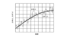
- it is a graph which shows the time transition of the coefficient update value before the filter process by the coefficient stabilization process part, and the stabilized coefficient update value after the filter process.
- It is a block diagram which shows the structure of the stabilization process part in the active noise control apparatus which concerns on Embodiment 3 of this invention.
- 10 is a flowchart showing an operation of a stabilization processing unit in the active noise control apparatus according to the third embodiment.
- 10 is a flowchart illustrating an operation of a coefficient stabilization processing unit in the active noise control device according to the third embodiment.
- FIG. 1 is a block diagram showing a configuration of an active noise control apparatus 100 according to Embodiment 1 of the present invention. As shown in the figure, an external output device 200 and a detector 300 are connected to the active noise control device 100.
- the active noise control device 100 receives the noise control frequency f (n) of the noise source 400 to be controlled, and outputs a control signal g (n) generated based on the input control frequency f (n).
- n is a positive integer and represents a sampling time in digital signal processing.
- the control frequency f (n) is determined by measuring the engine rotation frequency from the period of the ignition pulse and multiplying the rotation frequency by a constant according to the noise to be controlled. Can be obtained by the method.
- the control frequency f (n) of the NZ sound to be controlled is calculated from the number of poles and power supply frequency of the electric motor, the number of blades of the fan, and the like. Can do. As described above, the control frequency f (n) may be acquired by using means suitable for the target noise source 400.
- the output device 200 converts the control signal g (n) input from the active noise control device 100 into secondary noise for canceling the noise generated from the noise source 400 and outputs the secondary noise.
- the output device 200 can be realized by a speaker or an actuator, for example.
- the secondary noise output from the output device 200 propagates through the secondary path 500, interferes with noise generated from the noise source 400, and reduces the noise. Noise reduced by interference with secondary noise is called residual noise or error.
- the secondary path 500 is defined as a path through which the secondary noise output from the output device 200 passes while propagating to the detector 300.
- the disturbance source 600 further adds an unspecified disturbance unrelated to the noise source 400 to the residual noise. This disturbance includes extremely strong disturbances such as blowing sounds and striking sounds, and weak disturbances such as background sounds.
- the detector 300 detects a disturbance error in which a disturbance is added to an error, which is a residual noise generated by interference between noise and secondary noise, and the detected disturbance error is activated as an error signal e (n). This is output to the noise control device 100.
- This detector 300 can generally be realized by a microphone.
- the active noise control device 100 includes a sound source signal generation unit 1, a control signal filter 2, a reference signal filter 3, a filter coefficient update unit 4, and a stabilization processing unit 5.
- the sound source signal generation unit 1 is a signal generation unit that generates a sound source signal x (n) based on the control frequency f (n) input to the active noise control device 100.
- the sound source signal generation unit 1 outputs the generated sound source signal x (n) to the control signal filter 2 and the reference signal filter 3.
- the control signal filter 2 is a filter that performs a filtering process on the sound source signal x (n) from the sound source signal generation unit 1 and outputs an original control signal d (n).
- the control signal filter 2 outputs the original control signal d (n) to the stabilization processing unit 5.
- the control filter coefficient sequence W (n) used when the control signal filter 2 performs the filtering process is updated by the filter coefficient updating unit 4 described later.
- the reference signal filter 3 performs a filtering process on the sound source signal x (n) from the sound source signal generation unit 1 using a transfer characteristic parameter determined based on the transfer characteristic of the secondary path 500, and generates a reference signal r ( n).
- the reference signal filter 3 outputs the reference signal r (n) to the filter coefficient update unit 4.
- the filter coefficient updating unit 4 controls the control filter coefficient of the control signal filter 2 based on the reference signal r (n) from the reference signal filter 3, the error signal e (n) from the detector 300, and a predetermined step width. Update column W (n).
- the filter coefficient updating unit 4 uses an adaptive algorithm such as LMS (Least Mean Square), NLMS (Normalized Last Mean Square), or RLS (Recursive Last Square) for updating the control filter coefficient string W (n). it can.
- the predetermined step width is a value that is determined heuristically through experiments or the like and is preset in the filter coefficient updating unit 4.
- the filter coefficient update unit 4 calculates the coefficient update value, and the control signal filter 2 adds the coefficient update value to the control filter coefficient string W (n) to update the control filter coefficient string W (n). Good.
- the stabilization processing unit 5 performs stabilization processing for correcting the original control signal d (n) from the control signal filter 2 on the basis of the control frequency f (n) input to the active noise control device 100 to stabilize the stabilization.
- the generated control signal g (n) is generated.
- the stabilization processing unit 5 outputs the control signal g (n) to the output device 200.
- the control signal g (n) is a signal that is converted into secondary noise for reducing noise.
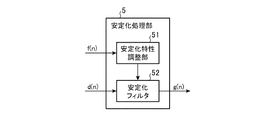
- FIG. 2 is a block diagram showing an internal configuration of the stabilization processing unit 5 in the active noise control apparatus 100 according to the first embodiment.
- the stabilization processing unit 5 of the first embodiment includes a stabilization characteristic adjustment unit 51 and a stabilization filter 52.
- the stabilization characteristic adjustment unit 51 adjusts the filter characteristic of the stabilization filter 52 so as to pass a signal in a frequency band including the control frequency f (n) and block a signal in a frequency band other than this.
- the stabilization characteristic adjustment unit 51 instructs the stabilization filter 52 to adjust the filter characteristics.
- the stabilization filter 52 is a filter that performs a filtering process on the original control signal d (n) from the control signal filter 2 and outputs a control signal g (n).
- the stabilization filter 52 adjusts the filter characteristics in accordance with instructions from the stabilization characteristic adjustment unit 51.
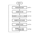
- FIG. 3 is a flowchart showing the operation of the active noise control apparatus 100 according to the first embodiment. Note that the order of processing performed by the active noise control apparatus 100 according to Embodiment 1 is not limited to the order shown in the flowchart of FIG. 3, and is performed in a different order as long as equivalent results are obtained. Alternatively, some processes may be parallelized.
- a control frequency f (n) representing a noise frequency is input to the sound source signal generation unit 1 and the stabilization processing unit 5 in the active noise control apparatus 100.
- n is a positive integer and represents a sampling time in digital signal processing.
- the sound source signal generation unit 1 acquires the control frequency f (n).
- the sound source signal generation unit 1 generates a sound source signal x (n) corresponding to the control frequency f (n) and outputs it to the control signal filter 2 and the reference signal filter 3.
- the sound source signal x (n) includes two signals of a sine wave signal and a cosine wave signal corresponding to the control frequency f (n). Is included.
- a suitable example of such a sound source signal generation method is disclosed in, for example, International Publication No. 2013/108294.
- the control signal filter 2 filters the sound source signal x (n) output from the sound source signal generation unit 1 using the control filter coefficient sequence W (n), and the original control signal d (n). Output to the stabilization processing unit 5.
- the control filter coefficient sequence W (n) is a filter coefficient sequence of the first order or higher order.
- the control filter coefficient sequence W (n) is also used for the filter coefficient sequence for the sine wave signal and the cosine wave signal. Including a sequence of filter coefficients.
- the control signal filter 2 adds a signal obtained by adding the filter processing result using the filter coefficient sequence for the sine wave signal and the filter processing result using the filter coefficient sequence for the cosine wave signal to the original control signal d ( n).
- step ST ⁇ b> 14 the stabilization processing unit 5 performs stabilization processing according to the control frequency f (n) on the original control signal d (n) output from the control signal filter 2, and is caused by the action of disturbance.
- a control signal g (n) in which the abnormal sound component is removed and stabilized is generated.
- the stabilization processing unit 5 outputs the generated control signal g (n) to the output device 200. Details of the operation of the stabilization processing unit 5 at this time will be described later.
- the output device 200 converts the control signal g (n) output from the stabilization processing unit 5 into secondary noise and outputs the secondary noise.
- the secondary noise output from the output device 200 propagates through the secondary path 500, and is affected by the transfer characteristics of the secondary path 500 in the process, and then interferes with the noise generated from the noise source 400. Reduce.
- the reduced noise is further subjected to disturbance from the disturbance source 600.
- the detector 300 detects the addition result of noise, secondary noise, and disturbance, that is, an error with disturbance added to the residual noise, and generates an error signal e (n).
- the error signal e (n) generated by the detector 300 is input to the filter coefficient update unit 4 in the active noise control device 100.
- the reference signal filter 3 filters the sound source signal x (n) output from the sound source signal generation unit 1 using the reference filter coefficient sequence C having the transfer characteristic of the secondary path 500, and refers to it.
- the signal r (n) is output to the filter coefficient update unit 4.
- the reference filter coefficient sequence C is a filter coefficient sequence of the first order or higher order.
- the reference filter coefficient sequence C is also a filter coefficient sequence for the sine wave signal and a filter coefficient for the cosine wave signal. Contains columns.
- the reference signal r (n) includes two systems of a filter processing result signal using a sine wave signal filter coefficient sequence and a filter processing result signal using a cosine wave signal filter coefficient sequence. included.
- step ST16 the filter coefficient updating unit 4 is based on the reference signal r (n) output from the reference signal filter 3, the error signal e (n) output from the detector 300, and a predetermined step width.
- the values of the control filter coefficient sequence W (n) of the control signal filter 2 are sequentially updated so that the residual noise included in the error signal e (n) is reduced.
- a well-known algorithm such as LMS, NLMS or RLS can be used.
- the filter coefficient updating unit 4 controls the control filter coefficient string W (n) so as to reduce the noise including the target noise. ).
- the sound source signal x (n) and the disturbance are irrelevant.
- there is no linear shift invariant filter that receives the sound source signal x (n) as an input and outputs a control signal g (n) that reduces disturbance. Therefore, the control filter coefficient sequence W (n) updated so as to reduce the disturbance included in the error signal e (n) at time n has a secondary noise reflecting the control filter coefficient sequence W (n). The disturbance at the time of output from the output device 200 is no longer effective.
- the component induced by the disturbance is only a mere contamination component that does not contribute to the reduction of noise or the disturbance targeted by the active noise control apparatus 100. Absent. However, the contamination component makes the original control signal d (n) output from the control signal filter 2 unstable and generates an abnormal sound component.
- the stabilization processing unit 5 removes the abnormal sound component from the original control signal d (n), changes it to the stabilized control signal g (n), and outputs it to the output device 200.
- the influence of the disturbance is suppressed without muting the control signal g (n) itself or suppressing the step width of the filter coefficient updating unit 4 as in the conventional case.
- the stabilization characteristic adjustment unit 51 allows the filter characteristic of the stabilization filter 52 to pass a signal in a frequency band having a predetermined bandwidth including the control frequency f (n) and cut off a signal in the other frequency band. adjust. For example, a low-pass characteristic that cuts off a frequency band that is higher than the control frequency f (n) by a predetermined frequency, or a high-pass characteristic that cuts off a frequency band that is lower than the control frequency f (n) by a predetermined frequency, or It is conceivable to provide the stabilization filter 52 with any one of the bandpass characteristics having both the lowpass characteristics and the highpass characteristics.
- the predetermined frequency is a value preset in the stabilization characteristic adjusting unit 51.
- This predetermined frequency is provided as a safety margin for preventing the stabilization filter 52 from affecting the signal of the control frequency f (n), and its value is determined empirically.
- the stabilization filter 52 holds a plurality of filter coefficient sequences having different bandpass characteristics in advance, and the stabilization characteristic adjustment unit 51 selects a filter coefficient sequence corresponding to the control frequency f (n) from among them. Select and instruct the stabilization filter 52.
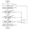
- FIG. 4 is a flowchart showing the operation of the stabilization processing unit 5 in the active noise control apparatus 100 according to the first embodiment.
- the process shown in the flowchart of FIG. 4 is a process performed in step ST14 in the flowchart of FIG.
- a method of selecting a filter coefficient sequence corresponding to the control frequency f (n) from M filter coefficient sequences having different bandpass characteristics will be described. It is assumed that M filter coefficient sequences held by the stabilization filter 52 are designated by the number m.
- step ST14-2 the stabilization characteristic adjustment unit 51 selects the mth filter coefficient sequence.
- step ST14-3 the stabilization characteristic adjustment unit 51 determines whether the high-frequency cutoff frequency in the filter characteristic of the mth filter coefficient sequence is higher than the control frequency f (n) by a predetermined threshold or more.
- the cutoff frequency on the high frequency side refers to a frequency at which the gain becomes a predetermined value or less when the frequency is higher than that frequency.
- the predetermined threshold is the same as the predetermined frequency described above. If the high-frequency cutoff frequency is higher than the control frequency f (n) by a predetermined threshold or more (step ST14-3 “YES”), the stabilization characteristic adjustment unit 51 proceeds to step ST14-4, and otherwise ( Step ST14-3 “NO”), the process proceeds to Step ST14-6.
- step ST14-4 the stabilization characteristic adjusting unit 51 determines whether or not the low-frequency cutoff frequency in the filter characteristic of the mth filter coefficient sequence is lower than the control frequency f (n) by a predetermined threshold or more.
- the cut-off frequency on the low frequency side refers to a frequency at which the gain becomes a predetermined value or lower when the frequency is lower than that frequency.
- the stabilization characteristic adjusting unit 51 proceeds to step ST14-5, and otherwise ( Step ST14-4 “NO”), the process proceeds to Step ST14-6.
- step ST14-5 the stabilization characteristic adjustment unit 51 instructs the stabilization filter 52 to select the m-th filter coefficient sequence that is currently selected.
- control frequency f (n) there are M filter coefficient sequences so that at least one filter coefficient sequence that satisfies the conditions of step ST14-3 and step ST14-4 always exists. It is assumed that it is given to the stabilization filter 52.
- step ST14-7 the stabilization filter 52 performs a filtering process on the original control signal d (n) using the filter coefficient sequence instructed by the stabilization characteristic adjustment unit 51, and outputs a control signal g (n). To do.
- the filter characteristic instructed by the stabilization characteristic adjustment unit 51 to the stabilization filter 52 passes a signal in a frequency band including the control frequency f (n) and blocks signals in other frequency bands. The generated abnormal sound component is removed.
- Each function of the sound source signal generation unit 1, the control signal filter 2, the reference signal filter 3, the filter coefficient update unit 4, and the stabilization processing unit 5 in the active noise control apparatus 100 is dedicated using an ASIC (Application Specific Integrated Circuit) or the like. It is also possible to realize this with hardware, or a processor that executes a program stored in the memory. Alternatively, it can be realized by combining electronic circuits, hardware such as LSI (Large Scale Integration), and a processor that executes a program stored in a memory.
- ASIC Application Specific Integrated Circuit
- FIG. 5 is a block diagram illustrating an example of a hardware configuration when the active noise control apparatus 100 according to the first embodiment is realized by the processor 1001 that executes a program stored in the memory 1002.
- the active noise control apparatuses 100 and 101 according to Embodiments 2 and 3 to be described later have the same basic hardware configuration as that shown in FIG.
- the functions of the sound source signal generation unit 1, the control signal filter 2, the reference signal filter 3, the filter coefficient update unit 4, and the stabilization processing unit 5 in the active noise control apparatus 100 are based on software, firmware, or a combination of software and firmware. Realized. Software or firmware is written as a program and stored in the memory 1002.
- the processor 1001 implements the functions of each unit by reading and executing a program stored in the memory 1002.
- the active noise control device 100 includes a memory 1002 for storing a program that, when executed by the processor 1001, results in each step shown in FIGS. It can also be said that the program causes the computer to execute the procedures or methods of the sound source signal generation unit 1, the control signal filter 2, the reference signal filter 3, the filter coefficient update unit 4, and the stabilization processing unit 5.
- control frequency f (n) is input from the external device to the active noise control device 100
- control signal g (n) is output from the active noise control device 100 to the output device 200
- the active noise control device from the detector 300 The input of the error signal e (n) to 100 is performed via the input / output interface 1003.
- a bus 1004 connects the processor 1001, the memory 1002, and the input / output interface 1003.
- the bus 1004 may be configured using a bus bridge or the like as appropriate.
- the control signal filter 2, the reference signal filter 3, and the stabilization filter 52 can be realized by analog filters or digital filters.
- a configuration example of the filter will be described using the stabilization filter 52 as an example.
- the stabilization filter 52 is configured by an analog filter, a variable resistance element is provided in the circuit, and the filter characteristic is adjusted by dynamically changing the resistance value according to an instruction from the stabilization characteristic adjustment unit 51.
- the stabilization filter 52 is configured by a digital filter
- the stabilization filter 52 is configured by a filter such as an FIR (Finite Impulse Response) filter or an IIR (Infinite Impulse Response) filter, and the filter coefficient is changed according to an instruction from the stabilization characteristic adjustment unit 51. To adjust the filter characteristics.
- the stabilization filter 52 is composed of a plurality of filters having different frequency bands as pass bands, and the outputs of the respective filters with respect to the original control signal d (n) are stabilized. Dynamic adjustment of the filter characteristics may be realized by a method such as selection by a selector according to an instruction from the characteristic adjustment unit 51, or mixing with a mixer by giving an appropriate gain.
- the active noise control device 100 generates a sound source signal x (n) based on the control frequency f (n) specified according to the noise source 400 that generates noise.
- a stabilization processing unit 5 that generates a control signal g (n) by performing a filtering process that passes a signal in a frequency band including noise and blocks a signal in a frequency band that includes disturbance added to noise, and a sound source signal x (n ) To generate a reference signal r (n), and an error signal obtained from the result of interference between secondary noise and noise generated based on the control signal g (n).
- a configuration and a filter coefficient updating unit 4 updates the control filter coefficient string W control signal filter 2 (n).
- the stabilization processing unit 5 instead of suppressing the step width of the filter coefficient updating unit 4, the stabilization processing unit 5 performs the stabilization process on the original control signal d (n). A decrease in the follow-up performance of the control signal g (n) with respect to the change can be prevented.
- Embodiment 2 The active noise control apparatus 100 according to the first embodiment removes abnormal noise by filtering the control signal g (n) with the stabilization filter 52. At this time, the delay due to the group delay characteristic of the stabilization filter 52 is eliminated. Is added to the control signal g (n). The delay due to the group delay characteristic is added to the delay time from when the filter coefficient updating unit 4 updates the control filter coefficient string W (n) until it receives the error signal e (n) reflecting the result, so that the group delay If the delay due to the characteristics is large, the follow-up performance with respect to the change in noise is reduced.
- the updated value of the control filter coefficient sequence W (n) is filtered, thereby obtaining the control signal g (n).
- An abnormal sound component is removed without adding a delay.
- FIG. 6 is a block diagram showing the configuration of the active noise control apparatus 101 according to Embodiment 2 of the present invention.
- Active noise control apparatus 101 according to Embodiment 2 has a configuration in which coefficient stabilization processing unit 6 is added instead of stabilization processing unit 5 in active noise control apparatus 100 of Embodiment 1 shown in FIG. .
- coefficient stabilization processing unit 6 is added instead of stabilization processing unit 5 in active noise control apparatus 100 of Embodiment 1 shown in FIG. .
- FIG. 6 the same or corresponding parts as those in FIG.
- the active noise control apparatus 101 includes a sound source signal generation unit 1, a control signal filter 2, a reference signal filter 3, a filter coefficient update unit 4, and a coefficient stabilization processing unit 6.
- the filter coefficient update unit 4 is connected to the reference signal filter 3, the coefficient stabilization processing unit 6, and the detector 300.
- the filter coefficient update unit 4 calculates a coefficient update value ⁇ W (n) based on the reference signal r (n) from the reference signal filter 3, the error signal e (n) from the detector 300, and a predetermined step width. Is output to the coefficient stabilization processing unit 6.
- the coefficient update value ⁇ W (n) is for updating the control filter coefficient string W (n) of the control signal filter 2.
- the coefficient stabilization processing unit 6 is connected to the control signal filter 2 and the filter coefficient update unit 4.
- the coefficient stabilization processing unit 6 performs a stabilization process on the coefficient update value ⁇ W (n) from the filter coefficient update unit 4 according to the control frequency f (n) input to the active noise control device 101, and A stabilization coefficient update value ⁇ W ′ (n) is generated.
- the coefficient stabilization processing unit 6 outputs the stabilized coefficient update value ⁇ W ′ (n) to the control signal filter 2.
- the control signal filter 2 is connected to the sound source signal generator 1, the coefficient stabilization processor 6, and the output device 200.
- the control signal filter 2 adds the stabilized coefficient update value ⁇ W ′ (n) from the coefficient stabilization processing unit 6 to the control filter coefficient string W (n), thereby obtaining the control filter coefficient string W (n). Update.
- the output of the control signal filter 2 is treated as a control signal g (n) and input to the output device 200.
- FIG. 7 is a block diagram showing an internal configuration of the coefficient stabilization processing unit 6 in the active noise control apparatus 101 according to the second embodiment.
- the coefficient stabilization processing unit 6 according to the second embodiment includes a stabilization characteristic adjustment unit 61 and a stabilization filter 62.
- the stabilization characteristic adjusting unit 61 adjusts the filter characteristic of the stabilization filter 62 according to the height of the control frequency f (n).
- the stabilization characteristic adjustment unit 61 instructs the stabilization filter 62 to adjust the filter characteristics.
- the stabilization filter 62 is a filter that performs a filter process on the coefficient update value ⁇ W (n) from the filter coefficient update unit 4 and outputs a stabilized coefficient update value ⁇ W ′ (n).
- the stabilization filter 62 adjusts the filter characteristics in accordance with instructions from the stabilization characteristic adjustment unit 61.
- FIG. 8 is a flowchart showing the operation of the active noise control apparatus 101 according to the second embodiment. Note that the order of processing performed by the active noise control apparatus 101 according to the second embodiment is not limited to the order shown in the flowchart of FIG. 8, and is performed in a different order as long as an equivalent result is obtained. Alternatively, some processes may be parallelized.
- a control frequency f (n) representing a noise frequency is input to the sound source signal generation unit 1 and the coefficient stabilization processing unit 6 in the active noise control apparatus 101.
- n is a positive integer and represents a sampling time in digital signal processing.
- the sound source signal generation unit 1 acquires a control frequency f (n).
- step ST22 the sound source signal generation unit 1 generates a sound source signal x (n) corresponding to the control frequency f (n), and outputs it to the control signal filter 2 and the reference signal filter 3.
- the control signal filter 2 filters the sound source signal x (n) output from the sound source signal generation unit 1 using the control filter coefficient sequence W (n), and outputs the control signal g (n). Output to the device 200.
- the reference signal filter 3 filters the sound source signal x (n) output from the sound source signal generation unit 1 using the reference filter coefficient sequence C having the transfer characteristic of the secondary path 500, and refers to it.
- the signal r (n) is output to the filter coefficient update unit 4.
- the filter coefficient updating unit 4 is based on the reference signal r (n) output from the reference signal filter 3, the error signal e (n) output from the detector 300, and a predetermined step width.
- the update value of the control filter coefficient sequence W (n) of the control signal filter 2 is calculated so that the residual noise included in the error signal e (n) is reduced, and the coefficient stabilization process is performed as the coefficient update value ⁇ W (n).
- the coefficient update value ⁇ W (n) includes an inappropriate component due to the action of the disturbance.
- step ST ⁇ b> 26 the coefficient stabilization processing unit 6 performs a stabilization process according to the control frequency f (n) on the coefficient update value ⁇ W (n) output from the filter coefficient update unit 4, and thereby causes a disturbance.
- a stabilized coefficient update value ⁇ W ′ (n) in which the control signal g (n) is stabilized by removing inappropriate components is generated.
- the coefficient stabilization processing unit 6 outputs the generated stabilized coefficient update value ⁇ W ′ (n) to the control signal filter 2.
- step ST27 the control signal filter 2 adds the stabilized coefficient update value ⁇ W ′ (n) output from the coefficient stabilization processing unit 6 to the control filter coefficient string W (n), so that the control filter coefficient string Update W (n).
- step ST26 details of the process of step ST26 by the stabilization characteristic adjusting unit 61 and the stabilization filter 62 of the coefficient stabilization processing unit 6 will be described.
- the stabilization characteristic adjustment unit 61 increases the control frequency f (n) when adjusting the filter characteristic of the stabilization filter 62.
- the stabilization characteristic adjustment unit 61 uses a filter coefficient sequence in which the cutoff frequency of the low-pass characteristic increases as the control frequency f (n) increases. 62. Thereby, the followability to noise is ensured.
- the stabilization filter 62 performs a filter process on the coefficient update value ⁇ W (n) from the filter coefficient update unit 4 using the filter coefficient string instructed from the stabilization characteristic adjustment unit 61, and provides a stabilized coefficient update value.
- ⁇ W ′ (n) is output.
- FIG. 9 shows the coefficient update value ⁇ W (n) calculated by the filter coefficient update unit 4 and the stabilized coefficient update value ⁇ W ′ (n) obtained by filtering the coefficient update value ⁇ W (n) by the coefficient stabilization processing unit 6. It is an example of the graph which shows the time transition of). As shown in the figure, the coefficient update value ⁇ W (n) before the filter processing by the stabilization filter 62 shows a minute variation in time. This fluctuation is an inappropriate component caused by disturbance, and does not contribute to noise reduction only by moving up and down finely on the graph. The stabilization filter 62 removes such inappropriate components due to its low-pass characteristics, and outputs a stable stabilized coefficient update value ⁇ W ′ (n) as shown in the figure. This avoids the generation of abnormal noise in the control signal g (n).
- the active noise control apparatus 101 can be realized by dedicated hardware using an ASIC or the like, and is stored in a memory. It is also possible to realize with a processor that executes the programmed program, or a combination of hardware such as an electronic circuit and LSI, and a processor that executes the program stored in the memory.
- the stabilization filter 62 can be realized by an analog filter or a digital filter.
- the active noise control apparatus 101 generates a sound source signal x (n) based on the control frequency f (n) specified according to the noise source 400 that generates noise.
- the filter coefficient updating unit 4 for calculating the coefficient update value ⁇ W (n) used for updating the control filter coefficient string W (n) of the control signal filter 2 and the characteristics of the control signal filter 2 are determined as follows:
- the control frequency f (n) of (n) is A coefficient stabilization processing unit 6 that performs a filter process on the coefficient update value ⁇ W (n) so as to have a characteristic that allows a signal in a frequency band to pass and blocks a signal in a frequency band including disturbance added to noise. It is a configuration. With this configuration, an abnormal sound component in the control signal g (n) can be removed without adding a delay to the control signal g (n). Therefore, abnormal noise caused by disturbance can be suppressed without impairing the noise-muffling effect.
- Embodiment 3 when the change in the frequency of noise is severe, the control signal g (n) is made to follow quickly by relaxing the stabilization process according to the frequency of the noise.
- the active noise control device 100 according to Embodiment 3 has the same configuration as that of the active noise control device 100 according to Embodiment 1 shown in FIG. 1, and the internal configuration is different only in the stabilization processing unit 5.
- FIG. 10 shows a block diagram of the stabilization processing unit 5 in the active noise control apparatus 100 according to the third embodiment.
- the stabilization processing unit 5 according to the third embodiment includes a stabilization characteristic adjustment unit 51, a stabilization filter 52, and a frequency change amount calculation unit 53.
- FIG. 11 is a flowchart showing the operation of the stabilization processing unit 5 in the third embodiment. Note that the order of processing performed by the stabilization processing unit 5 of the third embodiment is not limited to the order shown in the flowchart of FIG. 11, and is performed in a different order as long as an equivalent result is obtained. Alternatively, some processes may be parallelized.
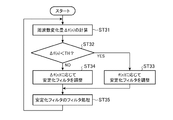
- the process shown in the flowchart of FIG. 11 is a process performed in step ST14 in the flowchart of FIG.
- the frequency change amount calculation unit 53 calculates the magnitude of the time change of the control frequency using the control frequency f (n), and outputs it to the stabilization characteristic adjustment unit 51 as the frequency change amount ⁇ f (n). To do.
- the frequency change amount ⁇ f (n) is calculated using, for example, the following equation (1). However, ⁇ is a real number satisfying 0 ⁇ ⁇ ⁇ 1.
- ⁇ f (n) ⁇ ⁇ ⁇ f (n ⁇ 1) + (1 ⁇ ) ⁇ (f (n) ⁇ f (n ⁇ 1)) (1)
- step ST32 the stabilization characteristic adjusting unit 51 compares the frequency change amount ⁇ f (n) output from the frequency change amount calculating unit 53 with a predetermined threshold value TH.
- the predetermined threshold TH is a value that is determined heuristically through experiments or the like and is preset in the stabilization characteristic adjusting unit 51. If ⁇ f (n) ⁇ TH (step ST32 “YES”), the stabilization characteristic adjusting unit 51 proceeds to step ST33. If ⁇ f (n) ⁇ TH (step ST32 “NO”), the process proceeds to step ST34. move on.
- step ST33 the stabilization characteristic adjustment unit 51 adjusts the filter characteristic of the stabilization filter 52 based on the control frequency f (n).
- the filter characteristic adjustment method in this case is the same as that in the first embodiment.
- the stabilization characteristic adjustment unit 51 adjusts the filter characteristic of the stabilization filter 52 based on the frequency change amount ⁇ f (n). For example, when the stabilization filter 52 is a filter having a low-pass characteristic, the stabilization characteristic adjustment unit 51 has a low-pass characteristic with a higher cutoff frequency as the frequency change amount ⁇ f (n) increases. Adjust. Thereby, when the change of the frequency of the noise is large, the pass band of the stabilization filter 52 is widened and the stabilization process is relaxed, so that the control signal g (n) can follow the rapidly changing noise. .
- step ST35 the stabilization filter 52 filters the original control signal d (n) according to the filter characteristic adjusted by the stabilization characteristic adjustment unit 51, and outputs the control signal g (n).
- the frequency change amount calculation unit 53 calculates the frequency change amount ⁇ f (n) indicating the magnitude of the time change of the control frequency f (n), and the stabilization characteristic adjustment unit 51.
- the stabilization filter 52 is adjusted so that the frequency band including the control frequency f (n) becomes the pass band, and the frequency change amount ⁇ f (
- n) is equal to or greater than a predetermined threshold TH
- the stabilization filter 52 is adjusted so as to have a low-pass characteristic such that the high-frequency cutoff frequency increases as the frequency change amount ⁇ f (n) increases.
- the stabilization process of the third embodiment may be applied to the coefficient stabilization processing unit 6 of the active noise control apparatus 101 according to the second embodiment.
- the active noise control apparatus 101 according to the third embodiment has the same configuration as that of the active noise control apparatus 101 according to the second embodiment shown in FIG. 6, and only the coefficient stabilization processing unit 6 has an internal configuration. Is different.
- FIG. 12 shows a block diagram of the coefficient stabilization processing unit 6 in the active noise control apparatus 101 according to the third embodiment.
- the coefficient stabilization processing unit 6 according to the third embodiment includes a stabilization characteristic adjustment unit 61, a stabilization filter 62, and a frequency change amount calculation unit 63.
- the frequency change amount calculation unit 63 uses the control frequency f (n) to calculate a frequency change amount ⁇ f (n) that indicates the magnitude of the time change of the control frequency, and outputs it to the stabilization characteristic adjustment unit 61.
- the stabilization characteristic adjustment unit 61 sets the control frequency f (n) as in the second embodiment.
- the filter characteristic of the stabilization filter 62 is adjusted so that the pass band changes according to the height.
- the stabilization characteristic adjusting unit 61 has a low-pass characteristic that increases the high-frequency cutoff frequency as the frequency change amount ⁇ f (n) increases.
- the active noise control device generates, for example, noise that cancels out noise generated by machinery and reduces it, and is suitable, for example, for reducing noise of an automobile engine.
Abstract
Description
なお、この発明において、機械類の発する振動または騒音を、まとめて騒音と称することとする。
上記特許文献2の方法を強度の弱い外乱に用いた場合、やはり、恒常的にステップ幅が抑制されることになるので、騒音の変化に対する追従性能が失われてしまう。
実施の形態1.
図1は、この発明の実施の形態1に係る能動騒音制御装置100の構成を示すブロック図である。図示のように、この能動騒音制御装置100には、外部に設けられた出力器200および検出器300が接続されている。
出力器200から出力された二次騒音は、二次経路500を伝播し、騒音源400から発生する騒音と干渉し、当該騒音を低減する。二次騒音との干渉により低減された騒音を、残留騒音または誤差と呼ぶ。ここで、二次経路500は、出力器200から出力された二次騒音が検出器300まで伝播する間に通過する経路と定義づけられる。また、外乱源600は、騒音源400とは無関係な不特定の外乱を、残留騒音に対してさらに付加するものである。この外乱は、吹かれ音および打撃音のような極端に強い外乱と、背景音のような強度の弱い外乱とを含む。
なお、フィルタ係数更新部4が係数更新値を算出し、制御信号フィルタ2が係数更新値を制御フィルタ係数列W(n)に加算することで制御フィルタ係数列W(n)を更新してもよい。
ステップST11において、音源信号生成部1は制御周波数f(n)を取得する。
また、音源信号x(n)が正弦波信号および余弦波信号の2系統の信号を含んでいる場合、制御フィルタ係数列W(n)も、正弦波信号用のフィルタ係数列および余弦波信号用のフィルタ係数列を含む。そして、制御信号フィルタ2は、正弦波信号用のフィルタ係数列を用いたフィルタ処理結果と、余弦波信号用のフィルタ係数列を用いたフィルタ処理結果とを加算した信号を、原制御信号d(n)とする。
低減された騒音は、さらに外乱源600からの外乱が加えられる。
また、音源信号x(n)が正弦波信号および余弦波信号の2系統の信号を含んでいる場合、参照フィルタ係数列Cも、正弦波信号用のフィルタ係数列および余弦波信号用のフィルタ係数列を含む。この場合、参照信号r(n)には、正弦波信号用のフィルタ係数列を用いたフィルタ処理結果の信号、および余弦波信号用のフィルタ係数列を用いたフィルタ処理結果の信号の2系統が含まれる。
ここでは、安定化フィルタ52が異なる帯域通過特性を持った複数のフィルタ係数列を予め保持しており、安定化特性調整部51はその中から制御周波数f(n)に応じたフィルタ係数列を選択して安定化フィルタ52に指示することとする。
以下では、例として、M個の異なるバンドパス特性を持ったフィルタ係数列の中から、制御周波数f(n)に応じたフィルタ係数列を選択する方法を説明する。安定化フィルタ52が保持しているM個のフィルタ係数列は、番号mによって指定されるものとする。
ステップST14-2において、安定化特性調整部51は、m番目のフィルタ係数列を選択する。
安定化特性調整部51は、高域側の遮断周波数が制御周波数f(n)より所定の閾値以上高い場合(ステップST14-3“YES”)、ステップST14-4に進み、それ以外の場合(ステップST14-3“NO”)、ステップST14-6に進む。
安定化特性調整部51は、低域側の遮断周波数が制御周波数f(n)より所定の閾値以上低い場合(ステップST14-4“YES”)、ステップST14-5に進み、それ以外の場合(ステップST14-4“NO”)、ステップST14-6に進む。
なお、ここでは、あらゆる制御周波数f(n)に対して、ステップST14-3およびステップST14-4の条件を満たすフィルタ係数列が必ず一つ以上は存在するように、M個のフィルタ係数列が安定化フィルタ52に与えられているものとしている。
能動騒音制御装置100における音源信号生成部1、制御信号フィルタ2、参照信号フィルタ3、フィルタ係数更新部4および安定化処理部5の各機能は、ASIC(Application Specific Integrated Circuit)等を用いた専用のハードウェアで実現することも可能であるし、メモリに格納されたプログラムを実行するプロセッサで実現することも可能である。あるいは、電子回路、LSI(Large Scale Integration)等のハードウェア、およびメモリに格納されたプログラムを実行するプロセッサを組み合わせて実現することも可能である。
能動騒音制御装置100における音源信号生成部1、制御信号フィルタ2、参照信号フィルタ3、フィルタ係数更新部4および安定化処理部5の各機能は、ソフトウェア、ファームウェア、またはソフトウェアとファームウェアとの組み合わせにより実現される。ソフトウェアまたはファームウェアはプログラムとして記述され、メモリ1002に記憶される。プロセッサ1001は、メモリ1002に記憶されたプログラムを読み出して実行することにより、各部の機能を実現する。すなわち、能動騒音制御装置100は、プロセッサ1001により実行されるときに、図3および図4で示した各ステップが結果的に実行されることになるプログラムを格納するためのメモリ1002を備える。また、プログラムは、音源信号生成部1、制御信号フィルタ2、参照信号フィルタ3、フィルタ係数更新部4および安定化処理部5の手順または方法をコンピュータに実行させるものであるともいえる。
バス1004は、プロセッサ1001、メモリ1002および入出力インタフェース1003を接続する。なお、バス1004は適宜バスブリッジ等を用いて構成されてもよい。
以下、安定化フィルタ52を例に用いてフィルタの構成例を説明する。安定化フィルタ52をアナログフィルタで構成する場合、回路内に可変抵抗素子を設け、その抵抗値を安定化特性調整部51の指示に従って動的に変更することによってフィルタ特性を調整する。安定化フィルタ52をデジタルフィルタで構成する場合、FIR(Finit Impulse Response)フィルタ、またはIIR(Infinit Impulse Response)フィルタなどのフィルタで構成し、そのフィルタ係数を安定化特性調整部51の指示に従って変更することによってフィルタ特性を調整する。また、アナログフィルタ、デジタルフィルタのいずれにおいても、安定化フィルタ52を、異なる周波数帯域を通過帯域とする複数のフィルタで構成し、原制御信号d(n)に対するそれぞれのフィルタの出力を、安定化特性調整部51の指示によってセレクタで選択するか、または適当な利得を与えてミキサで混合するなどの方法で、フィルタ特性の動的な調整を実現してもよい。
実施の形態1に係る能動騒音制御装置100は、制御信号g(n)を安定化フィルタ52でフィルタ処理することで異音を除去するが、この際、安定化フィルタ52の群遅延特性による遅延が制御信号g(n)に付与される。群遅延特性による遅延は、フィルタ係数更新部4が制御フィルタ係数列W(n)を更新してからその結果を反映した誤差信号e(n)を受け取るまでの遅延時間に加えられるため、群遅延特性による遅延が大きいと、騒音の変化に対する追従性能が低下する原因となる。そこで、実施の形態2では、制御信号g(n)を安定化フィルタ52で処理する代わりに、制御フィルタ係数列W(n)の更新値をフィルタ処理することで、制御信号g(n)に遅延を付与せずに異音成分の除去を行うようにする。
ステップST21において、音源信号生成部1は制御周波数f(n)を取得する。
ステップST23において、制御信号フィルタ2は、音源信号生成部1から出力された音源信号x(n)を、制御フィルタ係数列W(n)を用いてフィルタ処理し、制御信号g(n)を出力器200に出力する。
ステップST24において、参照信号フィルタ3は、音源信号生成部1から出力された音源信号x(n)を、二次経路500の伝達特性を備えた参照フィルタ係数列Cを用いてフィルタ処理し、参照信号r(n)をフィルタ係数更新部4に出力する。
制御周波数f(n)が高くなると騒音の時間変動も早くなることがあるため、安定化特性調整部61は、安定化フィルタ62のフィルタ特性を調整する際に制御周波数f(n)の高さに応じて通過帯域を調整する。例えば安定化フィルタ62がローパス特性を持つフィルタである場合、安定化特性調整部61は、制御周波数f(n)が高くなるほどローパス特性の遮断周波数が高くなるようなフィルタ係数列を、安定化フィルタ62に指示する。これにより、騒音への追従性を確保する。
また、安定化フィルタ62は、アナログフィルタまたはデジタルフィルタによって実現することができる。
実施の形態3では、騒音の周波数の変化が激しい場合に、騒音の周波数に応じて安定化処理を緩和することで、制御信号g(n)を速やかに追従させるようにする。
この図11のフローチャートに示された処理は、図3のフローチャートにおけるステップST14で実施される処理である。
周波数変化量Δf(n)は、例えば下式(1)を用いて計算される。ただし、αは0≦α<1を満たす実数とする。
=α×Δf(n-1)+(1-α)×(f(n)-f(n-1)) (1)
安定化特性調整部51は、Δf(n)<THである場合(ステップST32“YES”)、ステップST33に進み、Δf(n)≧THである場合(ステップST32“NO”)、ステップST34に進む。
周波数変化量算出部63は、制御周波数f(n)を用いて、制御周波数の時間変化の大きさを示す周波数変化量Δf(n)を計算し、安定化特性調整部61に出力する。
一方、周波数変化量Δf(n)が所定の閾値TH以上である場合、安定化特性調整部61は、周波数変化量Δf(n)が大きくなるに従って高域遮断周波数が高くなるようなローパス特性を持つように安定化フィルタ62のフィルタ特性を調整することによって、安定化処理を緩和する。
この構成により、騒音の周波数の変化に対して、能動騒音制御装置101の追従性を維持することができる。
Claims (6)
- 騒音を発する騒音源に応じて特定される制御周波数に基づいて音源信号を生成する音源信号生成部と、
前記音源信号に対しフィルタ処理を行って原制御信号を生成する制御信号フィルタと、
前記原制御信号のうちの前記制御周波数を含む周波数帯域の信号を通過させ、前記騒音に加わった外乱を含む周波数帯域の信号を遮断するフィルタ処理を行って制御信号を生成する安定化処理部と、
前記音源信号に対しフィルタ処理を行って参照信号を生成する参照信号フィルタと、
前記制御信号を元に生成された二次騒音と前記騒音との干渉の結果から得られる誤差信号、および前記参照信号を用いて、前記制御信号フィルタのフィルタ係数列を更新するフィルタ係数更新部とを備える能動騒音制御装置。 - 前記安定化処理部は、
前記原制御信号に対しフィルタ処理を行って前記制御信号を生成する安定化フィルタと、
前記制御周波数を含む周波数帯域が通過帯域となるように前記安定化フィルタを調整する安定化特性調整部とを有することを特徴とする請求項1記載の能動騒音制御装置。 - 前記安定化処理部は、前記制御周波数の時間変化の大きさを示す周波数変化量を算出する周波数変化量算出部を有し、
前記安定化特性調整部は、前記周波数変化量が予め定められた閾値未満の場合、前記制御周波数を含む周波数帯域が通過帯域となるように前記安定化フィルタを調整し、前記周波数変化量が前記予め定められた閾値以上の場合、前記周波数変化量が大きくなるに従って高域遮断周波数が高くなるようなローパス特性を持つように前記安定化フィルタを調整することを特徴とする請求項2記載の能動騒音制御装置。 - 騒音を発する騒音源に応じて特定される制御周波数に基づいて音源信号を生成する音源信号生成部と、
前記音源信号に対しフィルタ処理を行って制御信号を生成する制御信号フィルタと、
前記音源信号に対しフィルタ処理を行って参照信号を生成する参照信号フィルタと、
前記制御信号を元に生成された二次騒音と前記騒音との干渉の結果から得られる誤差信号、および前記参照信号を用いて、前記制御信号フィルタのフィルタ係数列の更新に使用される係数更新値を算出するフィルタ係数更新部と、
前記制御信号フィルタの特性が、前記音源信号のうちの前記制御周波数を含む周波数帯域の信号を通過させ、前記騒音に加わった外乱を含む周波数帯域の信号を遮断する特性になるよう、前記係数更新値に対しフィルタ処理を行う係数安定化処理部とを備える能動騒音制御装置。 - 前記係数安定化処理部は、
前記係数更新値に対しフィルタ処理を行う安定化フィルタと、
前記制御周波数の高さに応じて通過帯域が変化するように前記安定化フィルタを調整する安定化特性調整部とを有することを特徴とする請求項4記載の能動騒音制御装置。 - 前記係数安定化処理部は、前記制御周波数の時間変化の大きさを示す周波数変化量を算出する周波数変化量算出部を有し、
前記安定化特性調整部は、前記周波数変化量が予め定められた閾値未満の場合、前記制御周波数の高さに応じて通過帯域が変化するように前記安定化フィルタを調整し、前記周波数変化量が前記予め定められた閾値以上の場合、前記周波数変化量が大きくなるに従って高域遮断周波数が高くなるようなローパス特性を持つように前記安定化フィルタを調整することを特徴とする請求項5記載の能動騒音制御装置。
Priority Applications (4)
| Application Number | Priority Date | Filing Date | Title |
|---|---|---|---|
| US16/065,008 US10199033B1 (en) | 2016-02-09 | 2016-02-09 | Active noise control apparatus |
| PCT/JP2016/053820 WO2017138094A1 (ja) | 2016-02-09 | 2016-02-09 | 能動騒音制御装置 |
| DE112016006169.2T DE112016006169B4 (de) | 2016-02-09 | 2016-02-09 | Aktive Lärmschutzvorrichtung |
| JP2017566448A JP6351887B2 (ja) | 2016-02-09 | 2016-02-09 | 能動騒音制御装置 |
Applications Claiming Priority (1)
| Application Number | Priority Date | Filing Date | Title |
|---|---|---|---|
| PCT/JP2016/053820 WO2017138094A1 (ja) | 2016-02-09 | 2016-02-09 | 能動騒音制御装置 |
Publications (1)
| Publication Number | Publication Date |
|---|---|
| WO2017138094A1 true WO2017138094A1 (ja) | 2017-08-17 |
Family
ID=59562971
Family Applications (1)
| Application Number | Title | Priority Date | Filing Date |
|---|---|---|---|
| PCT/JP2016/053820 WO2017138094A1 (ja) | 2016-02-09 | 2016-02-09 | 能動騒音制御装置 |
Country Status (4)
| Country | Link |
|---|---|
| US (1) | US10199033B1 (ja) |
| JP (1) | JP6351887B2 (ja) |
| DE (1) | DE112016006169B4 (ja) |
| WO (1) | WO2017138094A1 (ja) |
Cited By (2)
| Publication number | Priority date | Publication date | Assignee | Title |
|---|---|---|---|---|
| CN108184192A (zh) * | 2017-12-27 | 2018-06-19 | 中山大学花都产业科技研究院 | 一种自适应声反馈抑制方法 |
| WO2022202018A1 (ja) * | 2021-03-24 | 2022-09-29 | 株式会社トランストロン | アクティブノイズ制御装置、アクティブノイズ制御方法及びアクティブノイズ制御プログラム |
Families Citing this family (3)
| Publication number | Priority date | Publication date | Assignee | Title |
|---|---|---|---|---|
| DE102020102946A1 (de) | 2020-02-05 | 2021-08-05 | Bayerische Motoren Werke Aktiengesellschaft | Verfahren zum Betreiben einer Ventilationsvorrichtung, Ventilationsvorrichtung und Kraftfahrzeug |
| JP2022108195A (ja) * | 2021-01-12 | 2022-07-25 | パナソニックIpマネジメント株式会社 | 能動騒音低減装置、移動体装置、及び、能動騒音低減方法 |
| EP4273853A4 (en) * | 2022-02-08 | 2024-04-24 | Shenzhen Shokz Co Ltd | ACTIVE NOISE REDUCTION AUDIO DEVICE, METHOD, AND STORAGE MEDIUM |
Citations (2)
| Publication number | Priority date | Publication date | Assignee | Title |
|---|---|---|---|---|
| WO2014128857A1 (ja) * | 2013-02-20 | 2014-08-28 | 三菱電機株式会社 | 能動振動騒音制御装置 |
| JP2015225130A (ja) * | 2014-05-26 | 2015-12-14 | 株式会社奥村組 | アクティブノイズコントロールシステム及びアクティブノイズコントロール方法 |
Family Cites Families (18)
| Publication number | Priority date | Publication date | Assignee | Title |
|---|---|---|---|---|
| US5524057A (en) * | 1992-06-19 | 1996-06-04 | Alpine Electronics Inc. | Noise-canceling apparatus |
| JPH06230788A (ja) * | 1993-02-01 | 1994-08-19 | Fuji Heavy Ind Ltd | 車室内騒音低減装置 |
| JP3919701B2 (ja) * | 2003-06-17 | 2007-05-30 | 本田技研工業株式会社 | 能動型振動騒音制御装置 |
| JP4664116B2 (ja) * | 2005-04-27 | 2011-04-06 | アサヒビール株式会社 | 能動騒音抑制装置 |
| JP4262703B2 (ja) * | 2005-08-09 | 2009-05-13 | 本田技研工業株式会社 | 能動型騒音制御装置 |
| JP4456577B2 (ja) * | 2006-03-31 | 2010-04-28 | 本田技研工業株式会社 | 能動型騒音制御装置及び能動型振動制御装置 |
| JP4999753B2 (ja) | 2008-03-31 | 2012-08-15 | パナソニック株式会社 | 能動型騒音制御装置 |
| EP2133866B1 (en) * | 2008-06-13 | 2016-02-17 | Harman Becker Automotive Systems GmbH | Adaptive noise control system |
| JP4926215B2 (ja) * | 2009-07-31 | 2012-05-09 | 本田技研工業株式会社 | 能動型振動騒音制御装置 |
| JP5312604B2 (ja) | 2009-10-07 | 2013-10-09 | パイオニア株式会社 | 能動型振動騒音制御装置 |
| US8600069B2 (en) * | 2010-03-26 | 2013-12-03 | Ford Global Technologies, Llc | Multi-channel active noise control system with channel equalization |
| JP5312685B2 (ja) * | 2010-04-09 | 2013-10-09 | パイオニア株式会社 | 能動型振動騒音制御装置 |
| US9484010B2 (en) * | 2011-01-06 | 2016-11-01 | Pioneer Corporation | Active vibration noise control device, active vibration noise control method and active vibration noise control program |
| JP5832839B2 (ja) | 2011-09-27 | 2015-12-16 | パイオニア株式会社 | 能動型騒音制御装置及び能動型騒音制御方法 |
| JP5616313B2 (ja) * | 2011-11-29 | 2014-10-29 | 本田技研工業株式会社 | 能動型振動騒音制御装置 |
| JP5757346B2 (ja) | 2012-01-20 | 2015-07-29 | 三菱電機株式会社 | 能動振動騒音制御装置 |
| US9626954B2 (en) | 2013-02-20 | 2017-04-18 | Mitsubishi Electric Corporation | Active vibration/noise control apparatus |
| JP6384784B2 (ja) * | 2014-08-05 | 2018-09-05 | パナソニックIpマネジメント株式会社 | 信号処理装置、プログラム、レンジフード装置 |
-
2016
- 2016-02-09 US US16/065,008 patent/US10199033B1/en active Active
- 2016-02-09 WO PCT/JP2016/053820 patent/WO2017138094A1/ja active Application Filing
- 2016-02-09 JP JP2017566448A patent/JP6351887B2/ja active Active
- 2016-02-09 DE DE112016006169.2T patent/DE112016006169B4/de active Active
Patent Citations (2)
| Publication number | Priority date | Publication date | Assignee | Title |
|---|---|---|---|---|
| WO2014128857A1 (ja) * | 2013-02-20 | 2014-08-28 | 三菱電機株式会社 | 能動振動騒音制御装置 |
| JP2015225130A (ja) * | 2014-05-26 | 2015-12-14 | 株式会社奥村組 | アクティブノイズコントロールシステム及びアクティブノイズコントロール方法 |
Cited By (2)
| Publication number | Priority date | Publication date | Assignee | Title |
|---|---|---|---|---|
| CN108184192A (zh) * | 2017-12-27 | 2018-06-19 | 中山大学花都产业科技研究院 | 一种自适应声反馈抑制方法 |
| WO2022202018A1 (ja) * | 2021-03-24 | 2022-09-29 | 株式会社トランストロン | アクティブノイズ制御装置、アクティブノイズ制御方法及びアクティブノイズ制御プログラム |
Also Published As
| Publication number | Publication date |
|---|---|
| US10199033B1 (en) | 2019-02-05 |
| JP6351887B2 (ja) | 2018-07-04 |
| DE112016006169T5 (de) | 2018-10-04 |
| JPWO2017138094A1 (ja) | 2018-04-12 |
| DE112016006169B4 (de) | 2021-07-01 |
| US20190019493A1 (en) | 2019-01-17 |
Similar Documents
| Publication | Publication Date | Title |
|---|---|---|
| JP6351887B2 (ja) | 能動騒音制御装置 | |
| JP3089082B2 (ja) | 適応型ディジタルフィルタ | |
| US6831986B2 (en) | Feedback cancellation in a hearing aid with reduced sensitivity to low-frequency tonal inputs | |
| JP4742226B2 (ja) | 能動消音制御装置及び方法 | |
| US10553195B2 (en) | Dynamic compensation in active noise reduction devices | |
| JP2012521020A (ja) | アクティブノイズリダクション適応フィルタリング | |
| JP2009258472A (ja) | 能動消音装置 | |
| JP2004354657A (ja) | 能動型騒音低減装置 | |
| EP3618058B1 (en) | Compensation and automatic gain control in active noise reduction devices | |
| JP2005257720A (ja) | 能動騒音制御装置 | |
| CN113811945B (zh) | 噪声消除信号饱和控制 | |
| US11232778B1 (en) | Systems and methods for detecting divergence in an adaptive system | |
| WO2017188133A1 (ja) | 能動型騒音低減装置及び能動型騒音低減方法 | |
| US20210193103A1 (en) | Feedfoward active noise control | |
| WO2020092510A1 (en) | Noise-cancellation systems and methods | |
| JP7162242B2 (ja) | 能動騒音低減装置、移動体装置、及び、能動騒音低減方法 | |
| JP6214884B2 (ja) | 能動消音装置および能動消音方法 | |
| JP5546795B2 (ja) | 対象波低減装置 | |
| JP2009302599A (ja) | 音響エコーキャンセラ | |
| WO2021100580A1 (ja) | 能動騒音低減装置、移動体装置、及び、能動騒音低減方法 | |
| JP2010276773A5 (ja) | ||
| JP2019203919A (ja) | ノイズ除去装置 | |
| JPH03237899A (ja) | ハウリング抑制装置 | |
| JP4516774B2 (ja) | 振動制御システム | |
| JP4133710B2 (ja) | 適応制御のスペクトルピーク平坦化処理 |
Legal Events
| Date | Code | Title | Description |
|---|---|---|---|
| 121 | Ep: the epo has been informed by wipo that ep was designated in this application |
Ref document number: 16889796 Country of ref document: EP Kind code of ref document: A1 |
|
| ENP | Entry into the national phase |
Ref document number: 2017566448 Country of ref document: JP Kind code of ref document: A |
|
| WWE | Wipo information: entry into national phase |
Ref document number: 112016006169 Country of ref document: DE |
|
| 122 | Ep: pct application non-entry in european phase |
Ref document number: 16889796 Country of ref document: EP Kind code of ref document: A1 |