WO2017135283A1 - 回転操作装置 - Google Patents
回転操作装置 Download PDFInfo
- Publication number
- WO2017135283A1 WO2017135283A1 PCT/JP2017/003550 JP2017003550W WO2017135283A1 WO 2017135283 A1 WO2017135283 A1 WO 2017135283A1 JP 2017003550 W JP2017003550 W JP 2017003550W WO 2017135283 A1 WO2017135283 A1 WO 2017135283A1
- Authority
- WO
- WIPO (PCT)
- Prior art keywords
- display
- unit
- light
- illumination light
- operation device
- Prior art date
- Legal status (The legal status is an assumption and is not a legal conclusion. Google has not performed a legal analysis and makes no representation as to the accuracy of the status listed.)
- Ceased
Links
Images

Classifications
-
- G—PHYSICS
- G05—CONTROLLING; REGULATING
- G05G—CONTROL DEVICES OR SYSTEMS INSOFAR AS CHARACTERISED BY MECHANICAL FEATURES ONLY
- G05G1/00—Controlling members, e.g. knobs or handles; Assemblies or arrangements thereof; Indicating position of controlling members
- G05G1/08—Controlling members for hand actuation by rotary movement, e.g. hand wheels
- G05G1/10—Details, e.g. of discs, knobs, wheels or handles
- G05G1/105—Details, e.g. of discs, knobs, wheels or handles comprising arrangements for illumination
-
- F—MECHANICAL ENGINEERING; LIGHTING; HEATING; WEAPONS; BLASTING
- F21—LIGHTING
- F21V—FUNCTIONAL FEATURES OR DETAILS OF LIGHTING DEVICES OR SYSTEMS THEREOF; STRUCTURAL COMBINATIONS OF LIGHTING DEVICES WITH OTHER ARTICLES, NOT OTHERWISE PROVIDED FOR
- F21V11/00—Screens not covered by groups F21V1/00, F21V3/00, F21V7/00 or F21V9/00
- F21V11/08—Screens not covered by groups F21V1/00, F21V3/00, F21V7/00 or F21V9/00 using diaphragms containing one or more apertures
-
- G—PHYSICS
- G05—CONTROLLING; REGULATING
- G05G—CONTROL DEVICES OR SYSTEMS INSOFAR AS CHARACTERISED BY MECHANICAL FEATURES ONLY
- G05G1/00—Controlling members, e.g. knobs or handles; Assemblies or arrangements thereof; Indicating position of controlling members
- G05G1/08—Controlling members for hand actuation by rotary movement, e.g. hand wheels
-
- G—PHYSICS
- G05—CONTROLLING; REGULATING
- G05G—CONTROL DEVICES OR SYSTEMS INSOFAR AS CHARACTERISED BY MECHANICAL FEATURES ONLY
- G05G25/00—Other details or appurtenances of control mechanisms, e.g. supporting intermediate members elastically
-
- H—ELECTRICITY
- H01—ELECTRIC ELEMENTS
- H01H—ELECTRIC SWITCHES; RELAYS; SELECTORS; EMERGENCY PROTECTIVE DEVICES
- H01H9/00—Details of switching devices, not covered by groups H01H1/00 - H01H7/00
- H01H9/16—Indicators for switching condition, e.g. "on" or "off"
-
- G—PHYSICS
- G05—CONTROLLING; REGULATING
- G05G—CONTROL DEVICES OR SYSTEMS INSOFAR AS CHARACTERISED BY MECHANICAL FEATURES ONLY
- G05G1/00—Controlling members, e.g. knobs or handles; Assemblies or arrangements thereof; Indicating position of controlling members
- G05G1/015—Arrangements for indicating the position of a controlling member
-
- H—ELECTRICITY
- H01—ELECTRIC ELEMENTS
- H01H—ELECTRIC SWITCHES; RELAYS; SELECTORS; EMERGENCY PROTECTIVE DEVICES
- H01H19/00—Switches operated by an operating part which is rotatable about a longitudinal axis thereof and which is acted upon directly by a solid body external to the switch, e.g. by a hand
- H01H19/02—Details
- H01H19/10—Movable parts; Contacts mounted thereon
- H01H19/11—Movable parts; Contacts mounted thereon with indexing means
Definitions
- the present invention relates to a rotary operation device.
- a dial operating device includes a first dial member and a second dial member that have a ring shape and rotate about the same axis, and a liquid crystal display disposed in the ring (see, for example, Patent Document 1). .)
- the dial operating device disclosed in Patent Document 1 has a problem that the number of parts increases and the cost increases by adopting a liquid crystal display.
- An object of the present invention is to provide a rotary operation device capable of performing display such as digital display at a low cost with an analog mechanism.
- a rotational operation device includes a light source that outputs illumination light, A display unit having a plurality of display objects formed in a circumferential direction, a transmission region that transmits the illumination light, and a light shielding region that blocks the illumination light; An operation unit that rotates together with the display unit in accordance with the rotation operation that is performed, is opaque, and is visible from the illumination light that is output from the light source and transmitted through the transmission region of the display unit. And having.
- a rotary operation device capable of performing display such as digital display at low cost with an analog mechanism.
- FIG. 1 is an exploded perspective view illustrating an example of a rotary operation device according to the embodiment.
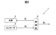
- FIG. 2 is a block diagram illustrating a configuration of the rotary operation device according to the embodiment.
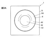
- FIG. 3A is an explanatory diagram illustrating a state before illumination of the rotary operation device according to the embodiment.
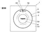
- FIG. 3B is an explanatory diagram illustrating a state after illumination of the rotation operation device.
- a rotation operation device includes a light source that outputs illumination light, a plurality of display objects formed in a circumferential direction, a display unit that includes a transmission region that transmits illumination light, and a light shielding region that blocks illumination light. And an operation unit that rotates together with the display unit in accordance with the rotation operation that is performed, is opaque, and allows the display target to be visually recognized by illumination light output from the light source and transmitted through the transmission region of the display unit.
- This rotary operation device is opaque when the operation unit is not illuminated, and has an analog mechanism that allows a display target to be visually recognized when illuminated. Compared to a case where such a mechanism is not employed.
- a display such as a digital display can be performed at a low cost by an analog mechanism.
- FIG. 1 is an exploded perspective view illustrating an example of a rotary operation device according to the embodiment.
- FIG. 2 is a block diagram illustrating a configuration of the rotary operation device according to the embodiment.
- FIG. 3A is an explanatory diagram illustrating a state before illumination of the rotary operation device according to the embodiment, and
- FIG. 3B is an explanatory diagram illustrating a state after illumination of the rotary operation device.
- the ratio between figures may be different from the actual ratio.
- main signals and information flows are indicated by arrows.
- the rotary operation device 1 is a dial-type operation device that sets the temperature, air volume, and the like of an air conditioner mounted on a vehicle.
- the rotation operation device 1 will be described as setting the temperature of the air conditioner.
- the rotary operation device 1 is not limited to an air conditioner, and may be used for volume adjustment of a music playback device.
- the rotary operation device 1 includes a light source 3 that outputs illumination light 30, a plurality of display objects in the circumferential direction, a transmission region that transmits the illumination light 30, and a light shielding that blocks the illumination light 30.
- the display unit 6 having a region, and the display unit 6 that rotates together with the display unit 6 in accordance with the rotation operation performed, is opaque, and is visually opaque by illumination light 30 transmitted through the transmission region of the display unit 6 by illumination with the light source 3.
- an operation unit 8 capable of
- the display target of the display unit 6 is, for example, a temperature display 601 as shown in FIG.
- This temperature display 601 is a number from 18 to 30, for example. This number indicates the set temperature of the air conditioner.
- Another display target of the support unit 7 described later is a function display 704.
- the support portion 7 is further formed with a pointer 700 as a display target.
- the rotation operation device 1 includes an encoder 4 as a rotation detection unit that detects rotation of the operation unit 8 through detection of rotation of the display unit 6, and the display unit 6 and the light source 3. Arranged between the light shielding unit 5 for shielding the illumination light 30 and between the display unit 6 and the operation unit 8 and supporting the rotation of the operation unit 8 and the display unit 6 as an integral unit. A support unit 7 that partially shields the illumination light 31 and a control unit 9 are provided.
- the light source 3 is arrange
- the light source 3 includes, for example, a light emitting element 3a and a light emitting element 3b as shown in FIG.
- the light emitting element 3a and the light emitting element 3b are, for example, LEDs (Light Emitting Diodes).
- the light emitting element 3a and the light emitting element 3b emit white illumination light 30 and illumination light 31, for example.
- the light emitting element 3 a is disposed below the transmission opening 50 of the light shielding unit 5. Accordingly, the illumination light 30 illuminates the display unit 6 through the transmission opening 50 of the light shielding unit 5 and causes the operation unit 8 to display the temperature display 601. Further, the illumination light 30 illuminates the conical portion 70 of the support portion 7 via the transmission opening 50 of the light shielding portion 5 and the display portion 6, and causes the operation portion 8 to display the pointer 700.
- the light emitting element 3 b is disposed below the cylindrical portion 71 of the support portion 7. Accordingly, the illumination light 31 illuminates the upper surface 701 of the support portion 7 via the cylindrical portion 71 of the support portion 7 inserted into the through hole 410 of the encoder 4 and causes the operation portion 8 to display the function display 704.
- the light source 3 is configured to emit light based on a drive signal S ⁇ b> 1 output from the control unit 9.
- the encoder 4 is configured to detect the amount of rotation of the operation unit 8 in the forward and reverse directions. Encoder 4 outputs to the control unit 9 the results of detecting a rotation amount information S 2.
- the encoder 4 includes, for example, a detection unit 40 and a rotation unit 41.
- the encoder 4 is an optical encoder of an increment type or an absolute type.
- the reference position of the encoder 4 is determined by, for example, a protrusion 710 of the support portion 7 described later.
- the protrusion 710 is inserted into the recess of the detection unit 40 of the encoder 4, so that the support unit 7 is attached to the detection unit 40 and the detection unit 40 and the support unit 7 are positioned.
- the detection unit 40 is attached to the substrate 2, for example.
- the rotating unit 41 is configured to rotate with respect to the detecting unit 40, for example.
- the rotating portion 41 has a cylindrical shape and has a through hole 410 formed therein.
- the cylindrical portion 71 of the support portion 7 is inserted into the through hole 410. Since the upper surface 411 of the rotation unit 41 is attached to the back surface 62 of the display unit 6, the rotation unit 41 rotates together with the display unit 6 and the operation unit 8.
- the rotation detection unit is not limited to the encoder 4, and may detect the rotation of the display unit 6 using a laser or the like.
- the light-shielding part 5 has a plate shape as shown in FIG.
- the light shielding portion 5 is formed using a material that does not transmit the illumination light 30.
- the light shielding unit 5 has a transmission opening 50 through which the illumination light 30 is transmitted, and the temperature display 601 and the pointer 700 are illuminated by the illumination light 30 transmitted through the transmission opening 50.
- the transmission opening 50 is formed below the temperature display 601 of the display unit 6.
- the transmissive aperture 50 has a shape corresponding to a display target to be illuminated and a display target on both sides of the display target. Specifically, for example, when the display target of the illumination target is “24” of the temperature display 601, the transmission opening 50 has a shape such that “23” and “25” on both sides thereof are illuminated. ing. The display objects on both sides are partially illuminated and displayed as a gradation display 15 as shown in FIG. 3B.
- the light shielding unit 5 further has an insertion opening 51.
- the cylindrical portion 71 of the support portion 7 and the rotating portion 41 of the encoder 4 are inserted into the insertion opening 51.
- the display unit 6 may have a protruding portion that protrudes from the rear surface 62 side, and this protruding portion may be inserted into the insertion opening 51 and attached to the rotating portion 41 of the encoder 4.
- the display unit 6 is formed in a disc shape using, for example, a synthetic resin material such as acrylic or polycarbonate. As described above, the display unit 6 includes a transmission region that transmits the illumination light 30 and a light-blocking region that blocks the illumination light 30. The light shielding area is the main body 60. Further, the transmission region is a temperature display 601 and a bottom surface 65.
- the temperature display 601 is displayed on the operation unit 8 in a pattern in which the temperature display 601 is an opening, the temperature display 601 does not pass the illumination light 30, and the periphery of the temperature display 601 transmits the illumination light 30.
- a pattern in which the inside of the temperature display 601 shields the illumination light 30 and the surrounding and the inside transmit the illumination light 30 is conceivable.
- the temperature display 601 of this embodiment is an opening and is formed using a laser or the like.
- the display unit 6 is painted in black except for the bottom surface 65 in order to shield light.
- the display unit 6 may be formed by two-color formation together with the main body 60 using a synthetic resin member that transmits the illumination light 30 as the temperature display 601, or a film on which the temperature display 601 is printed is pasted. May be formed.
- the main body 60 of the display unit 6 has a slope portion 63 on the surface 61.
- a temperature display 601 is formed on the slope portion 63.
- An accommodation portion 64 is formed at the center of the slope portion 63.
- the accommodating portion 64 has a concave shape cut out in a circular shape, and a conical portion 70 of the support portion 7 described later is inserted therein.
- a circular insertion opening 66 is formed at the center of the bottom surface 65 of the housing portion 64.
- the support portion 7 is formed using a synthetic resin material such as transparent acrylic or polycarbonate, for example.
- the support portion 7 has a conical portion 70 and a cylindrical portion 71.
- the support unit 7 includes a pointer 700 as a transmission unit that transmits a part of the illumination light 30 that has passed through the transmission opening 50 of the light shielding unit 5.
- the support portion 7 also has a function display 704 that transmits a part of the illumination light 31 that has propagated through the cylindrical portion 71.
- a side surface 702 of the conical portion 70 is painted in black to shield the illumination light 30.
- a pointer 700 for indicating a display target to be illuminated is formed in the vicinity of the outer periphery of the conical portion 70.
- the pointer 700 is an opening, for example, and is formed using a laser or the like.
- the conical portion 70 is cut off at an upper portion to form an upper surface 701.
- the upper surface 701 is painted black in order to block the illumination light 31, and a function display 704 is formed as an opening by a laser or the like.
- the function display 704 is formed at a location where the upper surface 701 is raised.
- the operation unit 8 is supported by the portion and becomes a shaft, and rotates together with the display unit 6.
- the function display 704 indicates function names that can be set by the rotary operation device 1.
- the function display 704 is displayed on the operation unit 8 when the illumination light 31 is transmitted.
- the cylindrical portion 71 is provided with the protrusion 710 on the lower side surface.
- the protrusion 710 is attached to the encoder 4.
- the illumination light 30 is emitted from the side surface 80 of the operation unit 8 via the bottom surface 65 of the display unit 6 and the pointer 700 of the conical unit 70 as shown in FIG. 3B. By this emission, the pointer 700 is displayed on the side surface 80 of the operation unit 8.
- the illumination light 31 is emitted from the upper surface 82 of the operation unit 8 via the tube unit 71 and the function display 704 as illustrated in FIG. 3B. By this emission, a function display 704 is displayed on the upper surface 82 of the operation unit 8.
- the operation unit 8 has a shape that is obtained by cutting an upper portion of a cone. The operator picks the side surface 80 of the operation unit 8 and rotates it forward and backward so that the desired set temperature is displayed. Note that the forward rotation is a clockwise rotation in which the number of the temperature display 601 becomes smaller on the paper surface of FIG. 3B. Further, the reverse rotation is a counterclockwise rotation in which the number of the temperature display 601 increases.
- An insertion recess 83 into which the conical portion 70 of the support portion 7 is inserted is provided on the lower surface 81 of the operation portion 8.
- the operation unit 8 is formed using, for example, a transparent synthetic resin material such as acrylic or polycarbonate. As shown in FIGS. 3A and 3B, the operation unit 8 is smoked so that the temperature display 601 of the display unit 6, the pointer 700 of the support unit 7, and the function display 704 cannot be visually recognized only by natural light.
- the operation unit 8 first cuts the synthetic resin material into the shape of the operation unit 8 and paints the cut out material with black so as to be smoked.
- the operation unit 8 is painted so that the light transmittance is 10% or less.
- the operation unit 8 may form smoke by diffusing a material that absorbs light, such as carbon black, in a synthetic resin material.
- the main body 10 of the rotary operation device 1 is made of the same material as that of the operation unit 8 and is similarly painted in black. Therefore, as shown in FIG. 3A, the rotation operation device 1 does not display the temperature display 601 of the display unit 6, the pointer 700 of the support unit 7, and the function display 704 only with natural light in a state where the light source 3 is not emitting light. , It will be blacked out.
- a circular recess 100 is formed in the main body 10 of the rotary operation device 1, and the operation unit 8 protrudes from the circular recess 100.
- the gap between the circular recess 100 and the operation unit 8 is so narrow that it is inconspicuous when blacked out.
- the outer peripheral part of the surface 101 of the main body 10 and the side surface 80 of the operation part 8 is connected smoothly.
- the control unit 9 includes, for example, a CPU (Central Processing Unit) that performs operations and processes on acquired data according to a stored program, a RAM (Random Access Memory) that is a semiconductor memory, a ROM (Read Only Memory), and the like. Microcomputer.
- ROM Read Only Memory
- a program for operating the control unit 9 is stored.
- the RAM is used as a storage area for temporarily storing calculation results and the like.
- the operator Before the operator turns on the power of the vehicle, as shown in FIG. 3A, the operator visually recognizes that the main body 10 and the operation unit 8 are black and nothing is displayed.
- the control unit 9 for example, when the power of the vehicle is turned on, and outputs to the light source 3 generates a driving signal S 1.
- the light emitting element 3 a and the light emitting element 3 b of the light source 3 output the illumination light 30 and the illumination light 31 based on the input drive signal S 1 , the illumination light 30 is illuminated by the transmission aperture 50 of the light shielding unit 5 and the display unit 6.
- the temperature display 601 and the adjacent temperature display 601 are output from the operation unit 8 so that the operator can visually recognize the temperature display 601 as being displayed on the operation unit 8 with a black background.
- the operator 700 can visually recognize the pointer 700 as being displayed on the operation unit 8 with a black background. .
- the operator can visually recognize the function display 704 as displayed on the operation unit 8 with a black background.
- control unit 9 rotates the display unit 6 and the rotation unit 41 of the encoder 4 together with the operation unit 8, and the rotation of the rotation unit 41 is detected by the detection unit 40.
- Encoder 4 generates the rotation amount information S 2 based on the rotation amount detected to the control unit 9.
- Control unit 9 generates and outputs to the air-conditioning apparatus operation information S 3 based on the rotation amount information S 2 acquired.
- the rotary operation device 1 can perform display such as digital display at a low cost with an analog mechanism.
- the rotary operation device 1 is opaque when the operation unit 8 is not illuminated, and has an analog mechanism that allows the temperature display 601, the pointer 700, and the function display 704 to be visible when illuminated. Yes. Therefore, the rotary operation device 1 can perform display such as digital display at a low cost with a simple analog mechanism as compared with a case where such a mechanism is not employed.
- the rotation operating device 1 can display the current set temperature numerically even if it does not include a liquid crystal display, it can be manufactured at a lower cost than when a liquid crystal display is employed.
- the rotary operation device 1 can be reduced in size as compared with the case where it is displayed outside the rotating operation unit.
- the rotation operation device 1 Since the rotation operation device 1 has a simple configuration, the display colors of the temperature display 601, the pointer 700, and the function display 704 can be easily changed by changing the colors of the illumination light 30 and the illumination light 31. Moreover, the rotation operating device 1 can change the display color easily because the temperature display 601, the pointer 700, and the function display 704 are formed of a colored synthetic resin material instead of an opening.
- the rotary operation device 1 Since the rotary operation device 1 displays the set temperatures before and after the current set temperature indicated by the pointer 700 as the gradation display 15, the operation direction and setting of the operation unit 8 are set as compared with the case where only the current set temperature is displayed. The relationship between the set temperatures is easy to understand. Further, since the set temperature before and after the rotary operation device 1 is mainly displayed in gradation, the current set temperature can be understood as compared with the case where the current set temperature and the set temperature before and after are illuminated in the same manner. easy.
- the rotary operation device 1 is excellent in design because when the power is turned on, a temperature display 601 or the like is displayed against a black background, and when the power is turned off, the display disappears and blacks out.
- the main body 10 and the operation portion 8 are formed using a transparent synthetic resin material, and the same black coating is applied, so that the main body 10 and the operation portion 8 are seamless and excellent in design. Yes.
Landscapes
- Engineering & Computer Science (AREA)
- Physics & Mathematics (AREA)
- General Physics & Mathematics (AREA)
- Automation & Control Theory (AREA)
- General Engineering & Computer Science (AREA)
- Rotary Switch, Piano Key Switch, And Lever Switch (AREA)
- Switch Cases, Indication, And Locking (AREA)
Abstract
回転操作装置1は、照明光30を出力する光源3と、周方向に形成された複数の表示対象と、照明光30を透過させる透過領域と照明光30を遮光する遮光領域とを有する表示部6と、なされた回転操作に伴って表示部6と一体に回転し、不透明であり、光源3から出力され表示部6の透過領域を透過した照明光30によって表示対象の視認を可能とする操作部8と、を有する。
Description
本発明は、回転操作装置に関する。
リング形状を有して同軸周りに回転する第1ダイヤル部材及び第2ダイヤル部材と、リング内に配置された液晶ディスプレイと、を備えたダイヤル操作装置が知られている(例えば、特許文献1参照。)。
特許文献1に開示されたダイヤル操作装置は、第1ダイヤル部材及び第2ダイヤル部材の操作内容が液晶ディスプレイに表示される。
特許文献1に開示されたダイヤル操作装置は、液晶ディスプレイを採用することで部品点数が増えてコストが増加する問題がある。
本発明の目的は、アナログな機構でデジタル表示のような表示を低コストで行うことができる回転操作装置を提供することにある。
本発明の一実施形態による回転操作装置は、照明光を出力する光源と、
周方向に形成された複数の表示対象と、前記照明光を透過させる透過領域と前記照明光を遮光する遮光領域とを有する表示部と、
なされた回転操作に伴って前記表示部と一体に回転し、不透明であり、前記光源から出力され前記表示部の前記透過領域を透過した前記照明光によって前記表示対象の視認を可能とする操作部と、を有する。
周方向に形成された複数の表示対象と、前記照明光を透過させる透過領域と前記照明光を遮光する遮光領域とを有する表示部と、
なされた回転操作に伴って前記表示部と一体に回転し、不透明であり、前記光源から出力され前記表示部の前記透過領域を透過した前記照明光によって前記表示対象の視認を可能とする操作部と、を有する。
本発明の一実施形態によれば、アナログな機構でデジタル表示のような表示を低コストで行うことができる回転操作装置を提供することができる。
(実施形態の要約)
実施形態に係る回転操作装置は、照明光を出力する光源と、周方向に形成された複数の表示対象と、照明光を透過させる透過領域と照明光を遮光する遮光領域とを有する表示部と、なされた回転操作に伴って表示部と一体に回転し、不透明であり、光源から出力され表示部の透過領域を透過した照明光によって表示対象の視認を可能とする操作部と、を有する。
実施形態に係る回転操作装置は、照明光を出力する光源と、周方向に形成された複数の表示対象と、照明光を透過させる透過領域と照明光を遮光する遮光領域とを有する表示部と、なされた回転操作に伴って表示部と一体に回転し、不透明であり、光源から出力され表示部の透過領域を透過した照明光によって表示対象の視認を可能とする操作部と、を有する。
この回転操作装置は、操作部が照明されていないと不透明であり、照明されると表示対象が視認可能となるアナログな機構を有しているので、このような機構を採用しない場合と比べて、アナログな機構でデジタル表示のような表示を低コストで行うことができる。
[実施形態]
(回転操作装置1の概要)
図1は、実施形態に係る回転操作装置の一例を示す分解斜視図である。図2は、実施形態に係る回転操作装置の構成を示すブロック図である。図3Aは、実施形態に係る回転操作装置の照明前の状態を示す説明図であり、図3Bは、回転操作装置の照明後の状態を示す説明図である。なお、以下に記載する実施形態に係る各図において、図形間の比率は、実際の比率とは異なる場合がある。また図2では、主な信号や情報の流れを矢印で示している。
(回転操作装置1の概要)
図1は、実施形態に係る回転操作装置の一例を示す分解斜視図である。図2は、実施形態に係る回転操作装置の構成を示すブロック図である。図3Aは、実施形態に係る回転操作装置の照明前の状態を示す説明図であり、図3Bは、回転操作装置の照明後の状態を示す説明図である。なお、以下に記載する実施形態に係る各図において、図形間の比率は、実際の比率とは異なる場合がある。また図2では、主な信号や情報の流れを矢印で示している。
この回転操作装置1は、一例として、車両に搭載される空調装置の温度や風量などを設定するダイヤル式の操作装置である。本実施形態では、回転操作装置1は、空調装置の温度を設定するものとして説明する。なお回転操作装置1は、空調装置に限定されず、音楽再生装置の音量調整などに用いられても良い。
回転操作装置1は、図1に示すように、照明光30を出力する光源3と、周方向に複数の表示対象が形成され、照明光30を透過させる透過領域と照明光30を遮光する遮光領域を有する表示部6と、なされた回転操作に伴って表示部6と一体に回転し、不透明であり、光源3による照明によって表示部6の透過領域を透過した照明光30によって表示対象の視認が可能となる操作部8と、を備えている。
この表示部6の表示対象は、例えば、図1に示すように、温度表示601である。この温度表示601は、例えば、18~30の数字である。この数字は、空調装置の設定温度を示している。また後述する支持部7の他の表示対象は、機能表示704である。この支持部7には、さらに表示対象としてポインタ700が形成されている。
また回転操作装置1は、図1及び2に示すように、表示部6の回転の検出を介して操作部8の回転を検出する回転検出部としてのエンコーダ4と、表示部6と光源3の間に配置され、照明光30を遮光する遮光部5と、表示部6と操作部8の間に配置され、操作部8と表示部6の一体となった回転を支持し、照明光30及び照明光31を部分的に遮光する支持部7と、制御部9と、を備えている。
(光源3の構成)
光源3は、例えば、プリント配線基板である基板2に配置されている。この光源3は、例えば、図1に示すように、発光素子3a及び発光素子3bを備えている。この発光素子3a及び発光素子3bは、一例として、LED(Light Emitting Diode)である。発光素子3a及び発光素子3bは、一例として、白色系の照明光30及び照明光31を出射する。
光源3は、例えば、プリント配線基板である基板2に配置されている。この光源3は、例えば、図1に示すように、発光素子3a及び発光素子3bを備えている。この発光素子3a及び発光素子3bは、一例として、LED(Light Emitting Diode)である。発光素子3a及び発光素子3bは、一例として、白色系の照明光30及び照明光31を出射する。
発光素子3aは、例えば、図1に示すように、遮光部5の透過開口50の下方に配置されている。従って照明光30は、遮光部5の透過開口50を介して表示部6を照明し、操作部8に温度表示601を表示させる。また照明光30は、遮光部5の透過開口50、及び表示部6を介して支持部7の円錐部70を照明し、操作部8にポインタ700を表示させる。
発光素子3bは、例えば、図1に示すように、支持部7の筒部71の下方に配置されている。従って照明光31は、エンコーダ4の貫通孔410に挿入された支持部7の筒部71を介して支持部7の上面701を照明し、操作部8に機能表示704を表示させる。
光源3は、例えば、図2に示すように、制御部9から出力される駆動信号S1に基づいて発光するように構成されている。
(エンコーダ4の構成)
エンコーダ4は、操作部8の正逆方向の回転量を検出するように構成されている。エンコーダ4は、検出した結果を回転量情報S2として制御部9に出力する。このエンコーダ4は、例えば、検出部40と、回転部41と、を有している。
エンコーダ4は、操作部8の正逆方向の回転量を検出するように構成されている。エンコーダ4は、検出した結果を回転量情報S2として制御部9に出力する。このエンコーダ4は、例えば、検出部40と、回転部41と、を有している。
エンコーダ4は、一例として、インクリメント型又はアブソリュート型の光学式のエンコーダである。このエンコーダ4の基準位置は、例えば、後述する支持部7の突起710によって決定される。この突起710は、例えば、エンコーダ4の検出部40の凹部に挿入されることで、検出部40に支持部7が取り付けられて検出部40と支持部7の位置決めがなされる。
検出部40は、例えば、基板2に取り付けられる。回転部41は、例えば、検出部40に対して回転するように構成されている。この回転部41は、円筒形状を有し、貫通孔410が形成されている。この貫通孔410には、支持部7の筒部71が挿入されている。そして回転部41の上面411は、表示部6の裏面62に取り付けられているので、回転部41が表示部6及び操作部8と共に回転する。
なお変形例として回転検出部は、エンコーダ4に限定されず、レーザなどを用いて表示部6の回転を検出するものであっても良い。
(遮光部5の構成)
遮光部5は、一例として、図1に示すように、板形状を有している。この遮光部5は、照明光30を透過しない材料を用いて形成されている。
遮光部5は、一例として、図1に示すように、板形状を有している。この遮光部5は、照明光30を透過しない材料を用いて形成されている。
遮光部5は、照明光30が透過する透過開口50を有し、透過開口50を透過した照明光30によって温度表示601とポインタ700が照明される。この透過開口50は、表示部6の温度表示601の下方に形成されている。
また透過開口50は、照明対象の表示対象と、当該表示対象の両隣の表示対象に応じた形状を有している。具体的には、透過開口50は、例えば、照明対象の表示対象が温度表示601の「24」であった場合、その両隣の「23」及び「25」が照明されるような形状を有している。そして両隣の表示対象は、図3Bに示すように、部分的に照明されてグラデーション表示15として表示される。
遮光部5は、さらに挿入開口51を有している。この挿入開口51には、支持部7の筒部71と、エンコーダ4の回転部41と、が挿入される。なお変形例として表示部6が裏面62側から突出する突出部を有し、この突出部が挿入開口51に挿入され、エンコーダ4の回転部41に取り付けられる構成でも良い。
(表示部6の構成)
表示部6は、例えば、アクリルやポリカーボネートなどの合成樹脂材料を用いて円板形状に形成されている。表示部6は、上述のように、照明光30を透過させる透過領域と、照明光30を遮光する遮光領域と、を有している。遮光領域は、本体60である。また透過領域は、温度表示601及び底面65である。
表示部6は、例えば、アクリルやポリカーボネートなどの合成樹脂材料を用いて円板形状に形成されている。表示部6は、上述のように、照明光30を透過させる透過領域と、照明光30を遮光する遮光領域と、を有している。遮光領域は、本体60である。また透過領域は、温度表示601及び底面65である。
ここで温度表示601を操作部8に表示させるパターンは、温度表示601が開口である、温度表示601が照明光30を通さず、その周囲が照明光30を透過させる、及び温度表示601の周囲と内部、つまり温度表示601の外形が照明光30を遮光し、周囲と内部が照明光30を透過させるなどのパターンが考えられる。
本実施形態の温度表示601は、開口であり、レーザなどを用いて形成される。そして表示部6は、例えば、遮光するために底面65以外が黒色で塗装されている。なお変形例として表示部6は、照明光30を透過させる合成樹脂部材を温度表示601に用いて本体60と共に二色形成によって形成されても良いし、温度表示601が印刷されたフィルムを貼り付けて形成されても良い。
表示部6の本体60は、表面61に斜面部63を有している。この斜面部63には、温度表示601が形成されている。また斜面部63の中央には、収容部64が形成されている。
収容部64は、円形に切り欠いた凹形状を有し、後述する支持部7の円錐部70が挿入される。また収容部64の底面65の中央には、円形の挿入開口66が形成されている。
(支持部7の構成)
支持部7は、例えば、透明なアクリルやポリカーボネートなどの合成樹脂材料を用いて形成されている。この支持部7は、円錐部70と、筒部71と、を有している。また支持部7は、遮光部5の透過開口50を通過した照明光30の一部を透過させる透過部としてのポインタ700を有している。また支持部7は、筒部71内を伝播した照明光31の一部を透過させる機能表示704を有している。
支持部7は、例えば、透明なアクリルやポリカーボネートなどの合成樹脂材料を用いて形成されている。この支持部7は、円錐部70と、筒部71と、を有している。また支持部7は、遮光部5の透過開口50を通過した照明光30の一部を透過させる透過部としてのポインタ700を有している。また支持部7は、筒部71内を伝播した照明光31の一部を透過させる機能表示704を有している。
円錐部70の側面702は、照明光30を遮光するため黒色で塗装されている。そして円錐部70の外周近傍には、照明対象の表示対象を指示するポインタ700が形成されている。このポインタ700は、例えば、開口であり、レーザなどを用いて形成される。
また円錐部70は、上部が切り取られて上面701が形成されている。この上面701は、照明光31を遮光するために黒色で塗装されると共に、レーザなどによって開口として機能表示704が形成されている。この機能表示704は、一例として、上面701が盛り上がった箇所に形成されている。操作部8は、当該箇所によって支持されて軸となり、表示部6と共に回転する。
この機能表示704は、回転操作装置1が設定できる機能名を示している。この機能表示704は、照明光31が透過することにより、操作部8に表示される。
筒部71は、上述のように、下部の側面に突起710が設けられている。この突起710は、エンコーダ4に取り付けられている。
照明光30は、一例として、図3Bに示すように、表示部6の底面65、及び円錐部70のポインタ700を介して操作部8の側面80から出射する。この出射によってポインタ700が操作部8の側面80に表示される。
また照明光31は、一例として、図3Bに示すように、筒部71及び機能表示704を介して操作部8の上面82から出射する。この出射によって機能表示704が操作部8の上面82に表示される。
(操作部8の構成)
操作部8は、図1に示すように、円錐の上部を切り取ったような形状を有している。操作者は、操作部8の側面80を摘まんで、希望の設定温度が表示されるように正逆回転させる。なお正回転は、図3Bの紙面において、温度表示601の数字が小さくなる時計回りの回転である。また逆回転は、温度表示601の数字が大きくなる反時計回りの回転である。
操作部8は、図1に示すように、円錐の上部を切り取ったような形状を有している。操作者は、操作部8の側面80を摘まんで、希望の設定温度が表示されるように正逆回転させる。なお正回転は、図3Bの紙面において、温度表示601の数字が小さくなる時計回りの回転である。また逆回転は、温度表示601の数字が大きくなる反時計回りの回転である。
操作部8の下面81には、支持部7の円錐部70が挿入される挿入凹部83が設けられている。
操作部8は、例えば、アクリルやポリカーボネートなどの透明な合成樹脂材料を用いて形成されている。操作部8は、図3A及び3Bに示すように、自然光のみでは、表示部6の温度表示601、支持部7のポインタ700、及び機能表示704が視認できないようにスモーク処理がなされている。
操作部8は、一例として、まず合成樹脂材料を操作部8の形状に削り出し、削り出したものを黒色で塗装してスモークとしている。この操作部8は、一例として、光の透過率が10%以下となるように塗装されている。なお変形例として操作部8は、例えば、合成樹脂材料にカーボンブラックなどの光を吸収する物質を拡散することによりスモークを形成するようにしても良い。
また回転操作装置1の本体10は、操作部8と同様の材料で形成され、また同様に黒色による塗装がなされている。従って回転操作装置1は、図3Aに示すように、光源3が発光していない状態の自然光のみでは、表示部6の温度表示601、支持部7のポインタ700、及び機能表示704が表示されず、ブラックアウトした状態となる。
回転操作装置1の本体10には、例えば、図3A及び3Bに示すように、円形凹部100が形成され、この円形凹部100から操作部8が突出している。この円形凹部100と操作部8との隙間は、ブラックアウトした際に目立たない程狭い。そして本体10の表面101と操作部8の側面80の外周部分は、滑らかに繋がっている。
(制御部9の構成)
制御部9は、例えば、記憶されたプログラムに従って、取得したデータに演算、加工などを行うCPU(Central Processing Unit)、半導体メモリであるRAM(Random Access Memory)及びROM(Read Only Memory)などから構成されるマイクロコンピュータである。このROMには、例えば、制御部9が動作するためのプログラムが格納されている。RAMは、例えば、一時的に演算結果などを格納する記憶領域として用いられる。
制御部9は、例えば、記憶されたプログラムに従って、取得したデータに演算、加工などを行うCPU(Central Processing Unit)、半導体メモリであるRAM(Random Access Memory)及びROM(Read Only Memory)などから構成されるマイクロコンピュータである。このROMには、例えば、制御部9が動作するためのプログラムが格納されている。RAMは、例えば、一時的に演算結果などを格納する記憶領域として用いられる。
操作者が車両の電源を投入する前、図3Aに示すように、本体10と操作部8が黒色に見えて何も表示されていないように操作者には視認される。
そして制御部9は、例えば、車両の電源が投入されると、駆動信号S1を生成して光源3に出力する。光源3の発光素子3a及び発光素子3bは、入力する駆動信号S1に基づいて照明光30及び照明光31を出力すると、照明光30が遮光部5の透過開口50、表示部6の照明対象の温度表示601、隣接する温度表示601を介して操作部8から出力するので、温度表示601が黒色を背景に操作部8に表示されているように操作者に視認される。
また照明光30は、透過開口50、表示部6及びポインタ700を介して操作部8から出力するので、ポインタ700が黒色を背景に操作部8に表示されているように操作者に視認される。
さらに照明光31は、筒部71及び機能表示704を介して操作部8から出力するので、機能表示704が黒色を背景に操作部8に表示されているように操作者に視認される。
そして制御部9は、操作部8が回転操作されると、操作部8と共に表示部6及びエンコーダ4の回転部41が回転し、この回転部41の回転を検出部40によって検出する。エンコーダ4は、検出した回転量に基づいた回転量情報S2を生成して制御部9に出力する。制御部9は、取得した回転量情報S2に基づいて操作情報S3を生成し空調装置に出力する。なお操作情報S3は、一例として、回転量を設定温度に変換した情報を含むがこれに限定されず、回転量の情報のみを含み、空調装置側で回転量を設定温度に変換する構成であっても良い。
(実施形態の効果)
本実施形態に係る回転操作装置1は、アナログな機構でデジタル表示のような表示を低コストで行うことができる。具体的には、回転操作装置1は、操作部8が照明されていないと不透明であり、照明されると温度表示601、ポインタ700及び機能表示704が視認可能となるアナログな機構を有している。従って回転操作装置1は、このような機構を採用しない場合と比べて、簡単なアナログな機構でデジタル表示のような表示を低コストで行うことができる。
本実施形態に係る回転操作装置1は、アナログな機構でデジタル表示のような表示を低コストで行うことができる。具体的には、回転操作装置1は、操作部8が照明されていないと不透明であり、照明されると温度表示601、ポインタ700及び機能表示704が視認可能となるアナログな機構を有している。従って回転操作装置1は、このような機構を採用しない場合と比べて、簡単なアナログな機構でデジタル表示のような表示を低コストで行うことができる。
回転操作装置1は、液晶ディスプレイを備えていなくても現在の設定温度を数字で表示することができるので、液晶ディスプレイを採用する場合と比べて、低コストで製造することができる。
回転操作装置1は、操作部8に温度表示601、ポインタ700及び機能表示704が表示されるので、回転する操作部の外に表示される場合と比べて、小型化することができる。
回転操作装置1は、構成が簡単であるので、照明光30及び照明光31の色を変えることで容易に温度表示601、ポインタ700及び機能表示704の表示色を変えることができる。また回転操作装置1は、温度表示601、ポインタ700及び機能表示704が開口ではなく、着色した合成樹脂材料により形成されることで、表示色を容易に変えることができる。
回転操作装置1は、ポインタ700が指し示す現在の設定温度の前後の設定温度をグラデーション表示15として表示するので、現在の設定温度のみが表示される場合と比べて、操作部8の操作方向と設定される設定温度の関連性が分かり易い。また回転操作装置1は、当該前後の設定温度が主にグラデーションで表示されるので、現在の設定温度と前後の設定温度とが同じように照明される場合と比べて、現在の設定温度が分かり易い。
回転操作装置1は、電源がオンにされると黒を背景に温度表示601などが表示され、電源がオフにされると表示が消えてブラックアウトするので意匠に優れている。
回転操作装置1は、透明な合成樹脂材料を用いて本体10及び操作部8が形成され、さらに同様の黒色の塗装が施されるので、本体10と操作部8とがシームレスで意匠に優れている。
以上、本発明のいくつかの実施形態及び変形例を説明したが、これらの実施形態及び変形例は、一例に過ぎず、特許請求の範囲に係る発明を限定するものではない。これら新規な実施形態及び変形例は、その他の様々な形態で実施されることが可能であり、本発明の要旨を逸脱しない範囲で、種々の省略、置き換え、変更などを行うことができる。また、これら実施形態及び変形例の中で説明した特徴の組合せの全てが発明の課題を解決するための手段に必須であるとは限らない。さらに、これら実施形態及び変形例は、発明の範囲及び要旨に含まれると共に、特許請求の範囲に記載された発明とその均等の範囲に含まれる。
1 回転操作装置
3 光源
5 遮光部
6 表示部
7 支持部
8 操作部
30,31 照明光
40 検出部
41 回転部
50 透過開口
601 温度表示
700 ポインタ
701 上面
704 機能表示
3 光源
5 遮光部
6 表示部
7 支持部
8 操作部
30,31 照明光
40 検出部
41 回転部
50 透過開口
601 温度表示
700 ポインタ
701 上面
704 機能表示
Claims (10)
- 照明光を出力する光源と、
周方向に形成された複数の表示対象と、前記照明光を透過させる透過領域と前記照明光を遮光する遮光領域とを有する表示部と、
なされた回転操作に伴って前記表示部と一体に回転し、不透明であり、前記光源から出力され前記表示部の前記透過領域を透過した前記照明光によって前記表示対象の視認を可能とする操作部と、を有する回転操作装置。 - 更に、前記表示部と前記光源の間に配置され、前記照明光を遮光する遮光部を有し、
前記遮光部は、前記照明光が透過する透過開口を有し、前記透過開口を透過した前記照明光によって前記表示部が照明される、請求項1に記載の回転操作装置。 - 更に、前記表示部と前記操作部の間に配置され、前記操作部と前記表示部の一体となった回転を支持し、前記照明光を部分的に遮光する支持部を有し、
前記支持部は、前記遮光部の前記透過開口を通過した前記照明光の一部を透過させる透過部を有する、請求項2に記載の回転操作装置。 - 前記支持部は、上面に形成され、前記照明光によって照明される他の表示対象を有する、請求項3に記載の回転操作装置。
- 前記遮光部の前記透過開口は、前記複数の表示対象のうちの照明対象としての一の表示対象と、前記一の表示対象の両隣の表示対象に応じた形状を有し、
前記両隣の表示対象は、部分的に照明されてグラデーション表示される、請求項2~4のいずれか1項に記載の回転操作装置。 - 前記表示部の回転の検出を介して前記操作部の回転を検出する回転検出部を有する、請求項1~5のいずれか1項に記載の回転操作装置。
- 前記表示部の前記透過領域は、前記複数の表示対象が形成された領域を含む、請求項1~6のいずれか1項に記載の回転操作装置。
- 前記操作部は、透明な合成樹脂材料を有し、前記合成樹脂材料は光透過率を下げる処理がなされているか又は光吸収物質を含んでいる、請求項1~7のいずれか1項に記載の回転操作装置。
- 前記合成樹脂材料の光透過率は、前記照明光が出力されない場合には、前記表示対象が視認されない程度に低下している、請求項1~8のいずれか1項に記載の回転操作装置。
- 前記合成樹脂材料の光透過率は、10%以下である、請求項9に記載の回転操作装置。
Priority Applications (2)
| Application Number | Priority Date | Filing Date | Title |
|---|---|---|---|
| CN201780007529.8A CN108475592A (zh) | 2016-02-05 | 2017-02-01 | 旋转操作装置 |
| US16/069,324 US20190018440A1 (en) | 2016-02-05 | 2017-02-01 | Rotational operation device |
Applications Claiming Priority (2)
| Application Number | Priority Date | Filing Date | Title |
|---|---|---|---|
| JP2016020502A JP2017139174A (ja) | 2016-02-05 | 2016-02-05 | 回転操作装置 |
| JP2016-020502 | 2016-02-05 |
Publications (1)
| Publication Number | Publication Date |
|---|---|
| WO2017135283A1 true WO2017135283A1 (ja) | 2017-08-10 |
Family
ID=59499668
Family Applications (1)
| Application Number | Title | Priority Date | Filing Date |
|---|---|---|---|
| PCT/JP2017/003550 Ceased WO2017135283A1 (ja) | 2016-02-05 | 2017-02-01 | 回転操作装置 |
Country Status (4)
| Country | Link |
|---|---|
| US (1) | US20190018440A1 (ja) |
| JP (1) | JP2017139174A (ja) |
| CN (1) | CN108475592A (ja) |
| WO (1) | WO2017135283A1 (ja) |
Families Citing this family (5)
| Publication number | Priority date | Publication date | Assignee | Title |
|---|---|---|---|---|
| JP6752104B2 (ja) * | 2016-10-24 | 2020-09-09 | 株式会社デンソーテン | 操作ボタン及び操作装置 |
| CN109164870A (zh) * | 2018-11-20 | 2019-01-08 | 深圳诺欧博智能科技有限公司 | 一种音量调节装置 |
| JP1662017S (ja) * | 2019-10-29 | 2020-06-22 | エアーコンディショナー | |
| JP1662018S (ja) * | 2019-10-29 | 2020-06-22 | エアーコンディショナー | |
| USD1099053S1 (en) * | 2024-06-19 | 2025-10-21 | Georg Schlegel Gmbh & Co. Kg | Electrical switch |
Citations (2)
| Publication number | Priority date | Publication date | Assignee | Title |
|---|---|---|---|---|
| JPS6019122U (ja) * | 1983-07-18 | 1985-02-08 | 古野電気株式会社 | 切り換えスイツチ取り付け構造体 |
| JPH0392329U (ja) * | 1990-01-05 | 1991-09-19 |
Family Cites Families (8)
| Publication number | Priority date | Publication date | Assignee | Title |
|---|---|---|---|---|
| JPH10188732A (ja) * | 1996-12-24 | 1998-07-21 | Fujitsu Ten Ltd | ツマミ |
| JP4584429B2 (ja) * | 2000-09-04 | 2010-11-24 | Hoya株式会社 | 照明付表示ダイヤル装置 |
| JP2007214006A (ja) * | 2006-02-10 | 2007-08-23 | Matsushita Electric Ind Co Ltd | スイッチ装置及びこれを用いた入力装置 |
| CN102592874A (zh) * | 2011-01-14 | 2012-07-18 | 上海德科电子仪表有限公司 | 风速控制开关 |
| JP2013054654A (ja) * | 2011-09-06 | 2013-03-21 | Tokai Rika Co Ltd | 操作装置 |
| WO2015003730A1 (en) * | 2013-07-08 | 2015-01-15 | Arcelik Anonim Sirketi | Household appliance with an improved front panel rotary selector switch |
| BR102013019899A2 (pt) * | 2013-08-05 | 2015-09-22 | Whirlpool Sa | sistema de iluminação seletiva para escala indicativa de manípulo rotativo e equipamento eletrodoméstico provido de sistema de iluminação seletiva para escala indicativa de manípulo rotativo |
| CN204834453U (zh) * | 2015-07-09 | 2015-12-02 | 瑞安市豪王汽车零部件有限公司 | 电动汽车挡位开关 |
-
2016
- 2016-02-05 JP JP2016020502A patent/JP2017139174A/ja active Pending
-
2017
- 2017-02-01 US US16/069,324 patent/US20190018440A1/en not_active Abandoned
- 2017-02-01 CN CN201780007529.8A patent/CN108475592A/zh active Pending
- 2017-02-01 WO PCT/JP2017/003550 patent/WO2017135283A1/ja not_active Ceased
Patent Citations (2)
| Publication number | Priority date | Publication date | Assignee | Title |
|---|---|---|---|---|
| JPS6019122U (ja) * | 1983-07-18 | 1985-02-08 | 古野電気株式会社 | 切り換えスイツチ取り付け構造体 |
| JPH0392329U (ja) * | 1990-01-05 | 1991-09-19 |
Also Published As
| Publication number | Publication date |
|---|---|
| JP2017139174A (ja) | 2017-08-10 |
| US20190018440A1 (en) | 2019-01-17 |
| CN108475592A (zh) | 2018-08-31 |
Similar Documents
| Publication | Publication Date | Title |
|---|---|---|
| WO2017135283A1 (ja) | 回転操作装置 | |
| JP6363456B2 (ja) | 車両用計器 | |
| JP6481551B2 (ja) | 表示装置 | |
| JP2008311056A (ja) | 表示装置 | |
| JP2007121177A (ja) | 指示計器 | |
| WO2015045328A1 (ja) | 表示装置 | |
| JP2010054326A (ja) | 指針式表示装置 | |
| JP6270611B2 (ja) | 指針計器 | |
| JP4536418B2 (ja) | 計器装置 | |
| JP6124057B2 (ja) | 車両用表示装置 | |
| JP2019087311A (ja) | 表示装置及び回転スイッチ | |
| JP6361363B2 (ja) | 表示装置 | |
| JP6532165B2 (ja) | 回転操作装置 | |
| JP5799775B2 (ja) | 表示装置 | |
| JP6451066B2 (ja) | 計器 | |
| JP2009042001A (ja) | 指針計器 | |
| JP4587705B2 (ja) | 計器装置 | |
| JP6610137B2 (ja) | 計器用表示装置 | |
| JP2009047560A (ja) | 計器装置 | |
| JP4835546B2 (ja) | 表示装置 | |
| JP6642239B2 (ja) | 表示装置 | |
| EP3086347A1 (en) | Rotational switching device | |
| JP6298701B2 (ja) | 指針計器 | |
| JPWO2019244813A1 (ja) | 計器装置 | |
| JP6298700B2 (ja) | 指針計器 |
Legal Events
| Date | Code | Title | Description |
|---|---|---|---|
| 121 | Ep: the epo has been informed by wipo that ep was designated in this application |
Ref document number: 17747439 Country of ref document: EP Kind code of ref document: A1 |
|
| NENP | Non-entry into the national phase |
Ref country code: DE |
|
| 122 | Ep: pct application non-entry in european phase |
Ref document number: 17747439 Country of ref document: EP Kind code of ref document: A1 |