WO2017135260A1 - ワイパ制御装置 - Google Patents
ワイパ制御装置 Download PDFInfo
- Publication number
- WO2017135260A1 WO2017135260A1 PCT/JP2017/003458 JP2017003458W WO2017135260A1 WO 2017135260 A1 WO2017135260 A1 WO 2017135260A1 JP 2017003458 W JP2017003458 W JP 2017003458W WO 2017135260 A1 WO2017135260 A1 WO 2017135260A1
- Authority
- WO
- WIPO (PCT)
- Prior art keywords
- wiper
- target
- rotation
- speed
- rotational speed
- Prior art date
- Legal status (The legal status is an assumption and is not a legal conclusion. Google has not performed a legal analysis and makes no representation as to the accuracy of the status listed.)
- Ceased
Links
Images



Classifications
-
- B—PERFORMING OPERATIONS; TRANSPORTING
- B60—VEHICLES IN GENERAL
- B60S—SERVICING, CLEANING, REPAIRING, SUPPORTING, LIFTING, OR MANOEUVRING OF VEHICLES, NOT OTHERWISE PROVIDED FOR
- B60S1/00—Cleaning of vehicles
- B60S1/02—Cleaning windscreens, windows or optical devices
- B60S1/04—Wipers or the like, e.g. scrapers
- B60S1/06—Wipers or the like, e.g. scrapers characterised by the drive
- B60S1/08—Wipers or the like, e.g. scrapers characterised by the drive electrically driven
Definitions
- the present invention relates to a wiper control device.
- the output shaft of the wiper motor depends on the position of the wiper blade on the windshield glass.
- the rotational speed of the output shaft of the wiper motor is controlled in accordance with a target speed table that defines the target rotational speed.
- FIG. 11 shows an example of the target speed table.
- FIG. 11 shows a target speed table 110 between the upside down positions used when the wiper blade performs a wiping operation between the lower inversion position and the upper inversion position.
- FIG. 11 also shows a storage position lower reverse position target speed table 111 used when the wiper blade is moved between the lower reverse position and the storage position where the wiper blade is stored when the wiper device is stopped.
- FIG. 11 shows a target speed table 112 between the storage position and the upper reverse position used when the wiper blade is moved from the storage position to the upper reverse position when the wiper device is started.
- the storage device In order to store all of these target speed tables, the storage device is required to have an appropriate capacity, which may hinder product cost reduction.
- each target speed table sets the target rotational speed in anticipation of the case where the wiper blade overruns when reversing and stopping.
- the target speed table 110 between the upside down positions is set such that the target rotation speed becomes 0 when the wiper blade reaches the storage position below the lower inversion position.
- the target speed table 111 between the storage position and the lower reversal position is set so that the target rotational speed becomes zero when the wiper blade reaches the upper reversal position above the lower reversal position.
- the target speed table 110 between the upside down positions and the target speed table 112 between the upside down positions of the storage positions are determined so that the target rotation speed becomes 0 when the wiper blade reaches above the upper inversion position. ing.
- the actual positions of the upper and lower reverse positions may not match the upper and lower reverse positions on the target speed table. May be located at the actual upper reversal position and lower reversal position, the target rotational speed may not become zero on the target speed table.
- the rotation of the wiper motor is controlled according to the target speed table to move the wiper blade to the upper reverse position.
- the rotation speed of the wiper motor may be rapidly increased at the start of the operation.
- the target rotational speed at the position where the wiper blade is stopped and the rotational speed in the stopped state (that is, 0)
- the rotational speed of the wiper motor may increase more rapidly immediately after starting.
- the target speed table includes an acceleration region in which the rotation speed of the wiper motor is accelerated immediately after starting, a constant speed region in which the rotation speed of the wiper motor is fixed after the acceleration region, and the like.
- a wiper motor control method and a motor control device are disclosed which are divided into a deceleration range in which the rotational speed of the wiper motor is reduced to 0 after the speed range.
- the rotation of the wiper motor is started at the start of the operation of the wiper blade by adjusting the length of the constant speed region of the target speed table according to the position at which the wiper blade starts to operate. The rotation of the wiper motor is controlled so that the speed increases smoothly from zero.
- a wiper control device that smoothly controls the rotation speed of the wiper motor when the wiper blade starts operation from an arbitrary position on the windshield glass. The purpose is to provide.
- the present disclosure includes a storage unit that stores rotational speed information that defines a target rotational speed of a wiper motor when the wiper blade is moved between one predetermined position and the other predetermined position; When the wiper blade starts an operation from the operation start position different from the one predetermined position and the other predetermined position, with the one predetermined position and the other predetermined position as the next movement destination, And a control unit that controls the rotational speed of the wiper motor using corrected rotational speed information obtained by correcting the rotational speed information based on the operation start position and the position of the next movement destination of the wiper blade.
- the rotational speed information that defines the target rotational speed of the output shaft of the wiper motor when the wiper blade is moved between one predetermined position and the other predetermined position is obtained from the operation start position, the wiper Correction is performed based on the position of the next movement destination of the blade.
- the rotational speed of the wiper motor can be smoothly controlled when the wiper blade starts operation from an arbitrary position on the windshield glass.
- the present disclosure includes a rotation angle detection unit that detects a rotation angle of the output shaft of the wiper motor, and the target rotation speed of the rotation speed information is determined corresponding to the rotation angle of the output shaft, and the control
- the correction unit is a ratio of a rotation angle range corresponding between the operation start position and the next movement destination and a rotation angle range corresponding between the one predetermined position and the other predetermined position.
- the corrected rotational speed information is obtained by correcting the target rotational speed based on the ratio.
- the ratio of the rotation angle range of the output shaft from the operation start position to the next destination with respect to the rotation angle range of the output shaft between one predetermined position and the other predetermined position is A certain correction ratio is calculated.
- control unit multiplies the rotation angle range corresponding to the rotation speed information between the one predetermined position and the other predetermined position by the correction ratio to rotate the rotation speed information.
- the corrected rotation speed information obtained by correcting the angle range and multiplying the target rotation speed of the rotation speed information with the corrected rotation angle range by the correction ratio is calculated between the operation start position and the next movement destination. To control the rotational speed of the wiper motor.
- the wiper control unit corrects the range of the rotation angle of the output shaft between the one predetermined position and the other predetermined position determined in the rotation speed information and the target rotation speed of the output shaft, thereby correcting the wiper.
- the rotation speed of the wiper motor can be controlled smoothly.
- the control unit when the signal for changing the movement speed of the wiper blade is input, the control unit is a coefficient based on the signal for changing the movement speed to the target rotation speed of the corrected rotation speed information. And the rotation speed of the wiper motor is controlled based on the corrected rotation speed information.
- the rotational speed information is corrected by multiplying a coefficient based on a signal that changes the speed of the wiper blade wiping operation, whereby the wiper blade can be moved at different wiping speeds according to one rotational speed information. Wiping operation can be performed. As a result, the capacity of the storage unit that stores the rotation speed information can be reduced, and the manufacturing cost of the product can be suppressed.
- the rotational speed information is determined such that the target rotational speed is discretely determined with respect to a discrete value of a rotational angle of an output shaft of the wiper motor, and the control unit Rotational speed between each value of the target rotational speed determined in (1) is calculated by linear interpolation.
- the rotation speed information holds a finite number of target rotation speed values, so that the wiper motor The rotational speed can be controlled smoothly.
- the capacity of the storage unit that stores the rotation speed information can be reduced, and the manufacturing cost of the product can be suppressed.
- an example of a second corrected target speed table in which the maximum value of the first corrected target speed table is corrected according to the reverse position is shown.
- it is the schematic which showed an example of the linear interpolation.
- it is a graph showing an example of the correspondence between the required wiping speed and the map coefficient, and an arbitrary wiping speed is designated as the required wiping speed between the wiping speed at the time of LO operation and the wiping speed at the time of HI operation. Shows the case.
- FIG. 1 is a schematic diagram showing a configuration of a wiper device 100 including a wiper control device 10 according to the present embodiment.
- the wiper device 100 has a left wiper device 14 on the left (passenger seat side) of the lower part of the windshield glass 12 of the vehicle and a right wiper device 16 on the right (driver's seat side) of the lower part of the windshield glass 12 of the vehicle.
- Each is a tandem wiper device.
- the left and right in the present embodiment are the left and right as viewed from the passenger compartment.
- the left wiper device 14 and the right wiper device 16 include wiper motors 18 and 20, speed reduction mechanisms 22 and 24, wiper arms 26 and 28, and wiper blades 30 and 32, respectively.
- the wiper motors 18 and 20 are provided on the lower left and lower right of the windshield glass 12, respectively.
- the forward and reverse rotations of the wiper motors 18 and 20 are respectively decelerated by the speed reduction mechanisms 22 and 24, and the output shafts 36 and 38 are respectively rotated by the forward and reverse rotations decelerated by the speed reduction mechanisms 22 and 24. Rotate. Further, the rotational forces of the forward and reverse rotations of the output shafts 36 and 38 act on the wiper arms 26 and 28, respectively, whereby the wiper arms 26 and 28 move from the storage position P3 to the lower inversion position P2, and the lower inversion position P2 and the upper inversion position It reciprocates between P1.
- the speed reduction mechanisms 22 and 24 are constituted by, for example, worm gears, and reduce the rotations of the wiper motors 18 and 20 to rotation speeds suitable for wiping the surface of the windshield glass 12 by the wiper blades 30 and 32, respectively. To rotate the output shafts 36 and 38 respectively.
- the wiper motors 18 and 20 have the speed reduction mechanisms 22 and 24 formed of worm gears, respectively. Therefore, the rotation speed and rotation angle of the output shafts 36 and 38 are determined by the wiper motor 18, It is not the same as the rotation speed and rotation angle of the 20 main body. However, in the present embodiment, since the wiper motors 18 and 20 and the speed reduction mechanisms 22 and 24 are inseparably configured, the rotational speeds and rotation angles of the output shafts 36 and 38 are hereinafter referred to as the respective wiper motors 18 and 20. Considered as rotation speed and rotation angle.
- the wiper motors 18 and 20 are connected to wiper control circuits 60 and 62 for controlling the rotation of the wiper motors 18 and 20, respectively.
- the wiper control circuit 60 according to the present embodiment includes a drive circuit 60A and a wiper ECU 60B, and the wiper control circuit 62 includes a drive circuit 62A and a wiper ECU 62B.
- a rotation angle sensor 42 for detecting the rotation speed and rotation angle of the output shaft 36 of the wiper motor 18 is connected to the wiper ECU 60B.
- a rotation angle sensor 44 that detects the rotation speed and rotation angle of the output shaft 38 of the wiper motor 20 is connected to the wiper ECU 62B.
- the wiper ECUs 60B and 62B calculate the positions of the wiper blades 30 and 32 on the windshield glass 12 based on the signals from the rotation angle sensors 42 and 44, respectively.
- the wiper ECUs 60B and 62B control the drive circuits 60A and 62A so that the rotation speeds of the output shafts 36 and 38 change according to the calculated positions.
- the rotation angle sensors 42 and 44 are provided in the speed reduction mechanisms 22 and 24 of the wiper motors 18 and 20, respectively, and convert the magnetic field (magnetic force) of the excitation coil or magnet that rotates in conjunction with the output shafts 36 and 38 into current. To detect.
- the drive circuits 60A and 62A generate voltages (currents) for operating the wiper motors 18 and 20, respectively, by PWM (Pulse Width) Modulation) control and supply them to the wiper motors 18 and 20, respectively.
- the drive circuits 60A and 62A include circuits using MOSFETs (metal oxide semiconductor field effect transistors) as switching elements.
- the drive circuit 60A is controlled by the wiper ECU 60B, and the drive circuit 62A is controlled by the wiper ECU 62B. Outputs the duty ratio voltage.
- the wiper ECU 60B and the wiper ECU 62B synchronize the operations of the left wiper device 14 and the right wiper device 16 by linking with communication using a protocol such as LIN (Local Interconnect Network).
- a wiper switch 66 is connected to the wiper ECU 62 ⁇ / b> B of the wiper control circuit 62 via the vehicle control circuit 64.
- the wiper switch 66 is a switch for turning on or off the power supplied to the wiper motors 18 and 20 from the vehicle battery.
- the wiper switch 66 is a low speed operation (LO operation) mode selection position for operating the wiper blades 30 and 32 at a low speed, a high speed operation (HI operation) mode selection position for operating at a high speed, and an intermittent operation in which the wiper blades 30 and 32 are intermittently operated at a constant cycle. Switching between the mode selection position and the stop mode selection position is possible.
- a command signal for rotating the wiper motors 18 and 20 according to the selected position in each mode is output to the wiper ECU 62B via the vehicle control circuit 64.
- the command signal input to the wiper ECU 62B is also input to the wiper ECU 60B by communication using the protocol such as the LIN described above.
- the wiper ECUs 60B and 62B When a signal output from the wiper switch 66 according to the selected position of each mode is input to the wiper ECUs 60B and 62B, the wiper ECUs 60B and 62B perform control corresponding to the output signal from the wiper switch 66. Specifically, the wiper ECUs 60B and 62B calculate the rotation speeds of the output shafts 36 and 38 based on a command signal from the wiper switch 66. Further, the wiper ECUs 60B and 62B control the drive circuits 60A and 62A so that the output shafts 36 and 38 rotate at the calculated rotational speed.
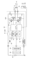
- FIG. 2 is a block diagram showing an example of a schematic configuration of the wiper control circuit 62 of the right wiper device 16 according to the present embodiment.
- the wiper motor 20 shown in FIG. 2 is a DC motor with a brush as an example.
- the configuration of the wiper control circuit 60 of the left wiper device 14 is the same as that of the wiper control circuit 62 of the right wiper device 16, and thus detailed description thereof is omitted.
- the wiper control circuit 62 shown in FIG. 2 is a microcomputer of a drive circuit 62A that generates a voltage to be applied to the winding terminal of the wiper motor 20, and a wiper ECU 62B that controls on and off of the switching elements constituting the drive circuit 62A. 48.
- the power of the battery 80 is supplied to the microcomputer 48 via the diode 56, and the voltage of the supplied power is detected by a voltage detection circuit 50 provided between the diode 56 and the microcomputer 48. The detection result is output to the microcomputer 48.
- An electrolytic capacitor C1 is provided between the diode 56 and the microcomputer 48, with one end connected and the other end (-) grounded.
- the electrolytic capacitor C ⁇ b> 1 is a capacitor for stabilizing the power supply of the microcomputer 48.
- the electrolytic capacitor C1 protects the microcomputer 48 by storing a sudden high voltage such as a surge and discharging it to the ground region.
- the microcomputer 48 receives a command signal for instructing the rotational speed of the wiper motor 18 from the wiper switch 66 and the vehicle control circuit 64 via the signal input circuit 52.
- the command signal output from the wiper switch 66 is an analog signal
- the signal is digitized by the signal input circuit 52 and input to the microcomputer 48.
- a rotation angle sensor 44 that detects a magnetic field of the sensor magnet 70 that changes in accordance with the rotation of the output shaft 38 is connected to the microcomputer 48.
- the microcomputer 48 determines the position of the wiper blades 30 and 32 on the windshield glass 12 by calculating the rotation angle of the output shaft 38 based on the signal output from the rotation angle sensor 44.
- the microcomputer 48 refers to the rotational speed data of the wiper motor 20 defined according to the position of the wiper blades 30 and 32 stored in the memory 54, and the rotation of the wiper motor 20 determines the specified wiper blade 30. , 32 is controlled so that the rotational speed is in accordance with the position of 32.
- the drive circuit 62A uses transistors Tr1, Tr2, Tr3, Tr4 which are N-type FETs (field effect transistors) as switching elements.
- the drains of the transistors Tr1 and Tr2 are connected to the battery 80 via the noise prevention coil 76, and the sources are connected to the drains of the transistors Tr3 and Tr4, respectively.
- the sources of the transistors Tr3 and Tr4 are grounded.
- the source of the transistor Tr1 and the drain of the transistor Tr3 are connected to one end of the winding of the wiper motor 18, and the source of the transistor Tr2 and the drain of the transistor Tr4 are connected to the other end of the winding of the wiper motor 18. .
- the transistors Tr2 and Tr3 when a high level signal is input to the gates of the transistors Tr2 and Tr3, the transistors Tr2 and Tr3 are turned on, and the wiper motor 20 has the wiper blades 30 and 32 viewed from the passenger compartment side, for example.
- a CCW current 74 that operates in a clockwise direction flows.
- the other when one of the transistors Tr2 and Tr3 is on-controlled, the other is controlled on and off by PWM control, whereby the voltage of the CCW current 74 can be modulated.
- a reverse connection protection circuit 58 and a noise prevention coil 76 are provided between the battery 80 as a power source and the drive circuit 62A, and an electrolytic capacitor C2 is provided in parallel with the drive circuit 62A. It has been.
- the noise prevention coil 76 is an element for suppressing noise generated by switching of the drive circuit 62A.
- the electrolytic capacitor C2 relieves noise generated from the drive circuit 62A, stores a sudden high voltage such as a surge, and discharges it to the ground region, whereby an excessive current is input to the high voltage drive circuit 62A. This is an element for preventing this.
- the reverse connection protection circuit 58 is a circuit for protecting the elements constituting the wiper control circuit 62 when the positive electrode and the negative electrode of the battery 80 are connected in reverse to the case shown in FIG.
- the reverse connection protection circuit 58 includes a so-called diode-connected FET or the like in which its drain and gate are connected.
- FIG. 3 shows an example of a target speed map in the wiper control device 10 according to the present embodiment.
- the horizontal axis of the target speed map in FIG. 3 is the rotation angle of the output shafts 36 and 38 of the wiper motors 18 and 20, and the vertical axis is the rotation speed of the output shafts 36 and 38 of the wiper motors 18 and 20.
- the rotation angles of the output shafts 36 and 38 are detected by the rotation angle sensors 42 and 44.
- the wiper control device 10 rotates the output shafts 36 and 38 when the wiper blades 30 and 32 are moved between the upper inversion position P1 and the lower inversion position P2.
- the memory 54 stores a target speed table 90 between the upside down positions in which the target rotational speeds of the output shafts 36 and 38 are determined in association with the change of.
- the wiper control device 10 according to the present embodiment outputs the wiper blades 30 and 32 in association with the change in the rotation angle of the output shafts 36 and 38 when the wiper blades 30 and 32 are moved between the storage position P3 and the lower inversion position P2.
- a storage speed lower reverse position target speed table 92 in which the target rotational speeds of the shafts 36 and 38 are determined is stored in the memory 54.
- the target speed table 90 between the upside down positions and the target speed table 92 between the lower positions of the reversing positions of the storage position are used for the output shafts 36 and 38 when the wiper blades 30 and 32 are moved between one predetermined position and the other predetermined position.
- the rotational speeds of the output shafts 36 and 38 are determined in association with changes in the rotational angle.
- the target rotational speed between the reversing positions below the retracted position accelerates the target rotational speed of the wiper motors 18 and 20 from 0, and the target rotational speed reaches the maximum value. After that, the speed is reduced and the target rotational speed is set to 0 when the wiper blades 30 and 32 reach the lower inversion position P2.
- the target speed table 90 between the upside down positions and the target speed table 92 between the inverted positions at the lower storage position are each composed of a smooth curve that is convex upward, and the target rotational speed simply increases from 0 to the maximum value, and the maximum value It is determined to monotonically decrease from 0 to 0.
- the target speed table 90 between the upside down positions and the target speed table 92 between the inverted positions at the lower storage position are corrected according to the position at which the wiper blades 30 and 32 start to reverse or operate.
- the target rotational speed of the wiper motor is calculated on the basis of the target speed table 90 between the upside down positions and the target speed table 92 between the reverse positions at the storage position.
- the positions of the wiper blades 30 and 32 are indicated by the rotation angles of the output shafts 36 and 38 detected by the rotation angle sensors 42 and 44, as an example.
- the target speed table 90 between the up and down inversion positions is stored.
- the correction is made in accordance with the position P3 and the upper inversion position P1, and is applied to the control of the rotational speed of the output shafts 36 and 38. Therefore, in this embodiment, a target speed table that defines the target rotation speed from the storage position P3 to the upper reversal position P1 is not required.
- the target speed table 92 between the storage position lower inversion positions is exceeded.
- the correction is made in accordance with the position of the wiper blades 30 and 32 after the run and the storage position P3, and is applied to control of the rotational speed of the output shafts 36 and 38.
- the target speed table 92 between the lower reversal positions of the storage position is set to the wiper before the lower reversal position P2.
- the correction is made in accordance with the position of the blades 30 and 32 and the storage position P3, and is applied to the control of the rotational speed of the output shafts 36 and 38.
- each target speed table shown in FIG. 3 differs from the target speed table shown in FIG. 11 in that the target rotational speed is set to 0 at each of the storage position P3, the lower reverse position P2, and the upper reverse position P1. Yes.
- the target speed table unlike the case shown in FIG. 11, it is not necessary to set the target speed table in anticipation of the overrun of the wiper blades 30 and 32, so that the target speed table can be easily set.
- FIG. 4 is a flowchart showing an example of target speed calculation processing of the wiper control device 10 according to the present embodiment.
- step 400 the reverse positions of the wiper blades 30 and 32 are detected from the rotation angles of the output shafts of the wiper motors 18 and 20 detected by the rotation angle sensors 42 and 44.
- the wiper blades 30 and 32 are not always reversed at the upper turning position P1 and the lower turning position P2.
- the wiper blades 30 and 32 stop the wiping operation from the upper reversal position P1 with the trouble of the lower reversal position P2, and the operation is stopped. Invert or start operation from position.
- step 402 the width of the basic table is corrected according to the reverse position of the wiper blades 30 and 32.
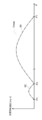
- FIG. 5 shows a target speed table between the upside down positions, which is a basic table, when the wiper blades 30 and 32 are reversed at the reverse position P4 before the lower reverse position P2 due to the influence of the obstacle on the windshield glass 12 or the like.
- a case where the first correction target speed table 94 is calculated by correcting the width of 90 is shown.
- the correction of the width of the basic table is performed, for example, between the change amount ⁇ 1 of the rotation angle of the output shafts 36 and 38 between the inversion position P4 and the upper inversion position P1, and between the lower inversion position P2 and the upper inversion position P1.
- a correction ratio K 1 which is a quotient of the rotation angle change amount ⁇ 0 of the output shafts 36 and 38, is calculated as in the following equation (1).
- the target speed table 90 between the upside down positions is expanded and contracted in the horizontal axis direction to calculate the first corrected target speed table 94, and the first corrected target speed table 94 is turned upside down with the reverse position P4. It applies between position P1.
- K 1 ⁇ 1 / ⁇ 0 (1)
- the target rotation speed is determined not by a continuous value but by a discrete finite number of values. Is.
- Various methods can be considered for the expansion / contraction processing in step 402. If the target speed table 90 between the upside down positions and the target speed table 92 between the bottom inverted positions are a set of discrete finite values, By multiplying the interval (angle) of adjacent values on the horizontal axis by the correction ratio K 1 described above, the target speed table 90 between the upside down positions and the target speed table 92 between the stored position lower reverse positions on the horizontal axis. The expansion / contraction process is performed.
- the first corrected target speed table 94 is generated by applying the target speed table 90 between the upside down positions subjected to the expansion / contraction processing on the horizontal axis between the inversion position P4 and the upper inversion position P1. is doing. More specifically, the first correction target speed table 94 is plotted by plotting each value of the target speed table 90 between the upside down positions subjected to the expansion / contraction processing on the horizontal axis from the inversion position P4 to the upper inversion position P1. Is calculated.
- step 404 the maximum value of the target rotational speed corresponding to the reverse position P4 is calculated.
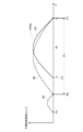
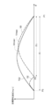
- FIG. 6 shows an example of the second corrected target speed table 96 in which the maximum value of the first corrected target speed table 94 is corrected according to the position of the reverse position P4.
- step 404 by multiplying the correction ratio K 1 to each value of the target rotational speed, including a maximum value of the first correction target speed table 94, the values including the maximum value is corrected in accordance with the inverted position P4 2 A correction target speed table 96 is calculated.
- step 406 linear interpolation is performed between the values of the target rotational speed in the second corrected target speed table 96.
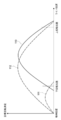
- FIG. 7 is a schematic diagram illustrating an example of linear interpolation.
- the target speed table 90 between the upside down positions which is a basic table, holds the target rotation speed as a discrete value instead of a continuous value. Since the second corrected target speed table 96 is based on the target speed table 90 between the upside down positions as the basic table as described above, the second corrected target speed table 96 similarly sets the target rotational speed to a finite number of discrete times. Holds by value.
- the number of finite numbers held by the target speed table 90 between the upside down positions and the second corrected target speed table 96 is about 20 to 100 as an example, but the specific number is the specification of the wiper device 100 or the like. To be decided.
- the wiper motors 18 and 20 are switched when the control according to one target rotation speed is switched to the control according to the next target rotation speed. There is a risk that the rotation of the will become irregular. Therefore, in this embodiment, the values of the target speeds discretely determined in the second correction target speed table 96 are interpolated by the linear interpolation shown in FIG.
- the target rotational speed is corrected according to the required wiping speed.
- a wiper device for a vehicle switches the wiping speed of a wiper blade between a high speed HI operation and a low speed LO operation.
- the wiping speed of the wiper blade may be arbitrarily set between the wiping speed at the time of LO operation and the wiping speed at the time of HI operation.
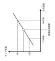
- FIG. 8 is a graph showing an example of the correspondence between the required wiping speed and the map coefficient.
- An arbitrary wiping speed is designated as the required wiping speed between the wiping speed at the LO operation and the wiping speed at the HI operation. Shows the case.
- the third correction target speed table 98 corresponding to the required wiping speed is calculated by multiplying each value of the second correction target speed table 96 by the map coefficient corresponding to the designated required wiping speed.
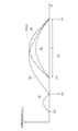
- FIG. 9 is a schematic diagram showing an example of the third correction target speed table 98.
- the target rotation speed indicated by the third correction target speed table 98 is lower than the target rotation speed indicated by the second correction target speed table 96.
- FIG. 9 shows a case where each value of the second corrected target speed table 96 is multiplied by a map coefficient of 0 or more and 1 or less.
- each value in the second corrected target speed table 96 is multiplied by one or more map coefficients.
- the wiper motors 18 and 20 are controlled so as to have a rotational speed corresponding to the reversal position by correcting the target speed table 90 between the vertical reversal positions as a basic table according to the reversal position. Accordingly, when the wiper blades 30 and 32 are reversed or started to move from positions different from the lower reversal position P2 and the upper reversal position P1, the rotational speeds of the output shafts 36 and 38 of the wiper motors 18 and 20 change rapidly. Thus, the rotational speed of the wiper motors 18 and 20 can be controlled smoothly. As a result, the wiping speed of the wiper blades 30 and 32 can be changed smoothly.
- the target speed table stored in the memory 54 is a target speed table 90 between the upside down positions, which is a basic table.
- a storage position lower reverse position target speed table 92 that defines a target rotational speed of the wiper motors 18 and 20 between the storage position P3 and the lower reverse position P2 is stored in the memory 54. You just have to.
- the target speed table stored in advance in the memory 54 may be the target speed table 90 between the upside down positions and the target speed table 92 between the stored position and the lower inverted position.
- the capacity of the storage device of the wiper device can be suppressed as compared with the case where a plurality of storage capacities are stored according to the required wiping speed, and the production cost of the product can be reduced.
- the wiper blades 30 and 32 start operation by reversal or the like at a position before the lower reversal position P2 (from the upper reversal position P1 side) has been described.
- the target speed table 90 between the vertical reversal positions which is the basic table, is corrected.
- the rotational speeds of the wiper motors 18 and 20 are smoothly controlled.
- FIG. 10 is a schematic diagram illustrating an example of the fourth corrected target speed table 102 when the wiper blades 30 and 32 start to operate from the storage position P3.
- the calculation procedure of the fourth correction target speed table 102 is the same as that of the third correction target speed table 98 described above. That is, the width of the upper and lower reversal position between the target speed table 90 is corrected in accordance with the storage position P3 by using the correction ratio K 2 calculated by the following equation (2).
- K 2 ⁇ 2 / ⁇ 0 (2)
- the correction ratio K 2 by multiplying each value including the maximum value of the target rotational speed of the target speed table corrected according to the storage position P3 width, in accordance with the maximum value V max in the storage position P3
- a fourth corrected target speed table 102 corrected to V max2 is calculated.
- the calculated fourth corrected target speed table 102 not only moves the wiper blades 30 and 32 from the storage position P3 to the upper inversion position P1, but also moves the wiper blades 30 and 32 from the upper inversion position P1 to the storage position P3. It can also be applied to
- a target speed table necessary for the rotational speed of the wiper motors 18 and 20 is obtained by multiplying each value of the fourth corrected target speed table 102 by a map coefficient corresponding to the required wiping speed. calculate.
- the rotation speed according to the reverse position or the position where the operation starts is obtained.
- the wiper motors 18 and 20 are controlled. Accordingly, when the wiper blades 30 and 32 are reversed or started to move from positions different from the lower reversal position P2 and the upper reversal position P1, the rotational speeds of the output shafts 36 and 38 of the wiper motors 18 and 20 change rapidly. Thus, the rotational speed of the wiper motors 18 and 20 can be controlled smoothly. As a result, the wiping speed of the wiper blades 30 and 32 can be changed smoothly.
- the wiper control device 10 may be used for a wiper device having a link mechanism in addition to the tandem wiper device 100 having no link mechanism.
Landscapes
- Engineering & Computer Science (AREA)
- Mechanical Engineering (AREA)
- Control Of Electric Motors In General (AREA)
- Control Of Direct Current Motors (AREA)
Abstract
ワイパ制御回路は、ワイパブレードを下反転位置と上反転位置との間を移動させる際のワイパモータの出力軸の回転角度の変化に対応付けて当該出力軸の目標回転速度を定めた上下反転位置間目標速度テーブルを、ワイパブレードが下反転位置及び上反転位置とは異なる反転位置から下反転位置及び上反転位置のいずれかを次の移動先として動作を開始する場合に、前述の異なる反転位置と、ワイパブレードの次の移動先の位置と、に基づいて上下反転位置間目標速度テーブルを補正して第2補正目標速度テーブルを生成し、第2補正目標速度テーブルに基づいて出力軸の回転速度を制御する。
Description
本発明は、ワイパ制御装置に関する。
ワイパブレードをウィンドシールドガラス上の上反転位置と下反転位置との間を往復動作させてウィンドシールドガラス表面を払拭するワイパ装置では、ワイパブレードのウィンドシールドガラス上の位置に応じてワイパモータの出力軸の目標回転速度を定めた目標速度テーブルに従ってワイパモータの出力軸の回転速度を制御する。
図11は、目標速度テーブルの一例を示している。図11には、ワイパブレードが下反転位置と上反転位置との間を払拭動作する場合に用いられる上下反転位置間目標速度テーブル110が記載されている。また、図11には、下反転位置とワイパ装置の停止時にワイパブレードが格納される格納位置との間でワイパブレードを移動させる場合に用いられる格納位置下反転位置間目標速度テーブル111が記載されている。さらに図11には、ワイパ装置の始動時に格納位置から上反転位置にワイパブレードを移動させる場合に用いられる格納位置上反転位置間目標速度テーブル112が記載されている。
図11に示したように、停止時に下反転位置よりも下方にワイパブレードを格納する、いわゆるコンシールドタイプのワイパ装置では、必要とされる目標速度テーブルは数種類に及ぶ。これらの目標速度テーブル全てを記憶させるには、記憶装置に相応の容量が要求され、製品のコスト削減の阻害要因となるおそれがあった。
また、図11に示したように、目標速度テーブルの各々は反転時及び停止時にワイパブレードがオーバーランする場合を見越して目標回転速度を設定している。例えば、上下反転位置間目標速度テーブル110は、下反転位置よりも下方の格納位置寄りにワイパブレードが到達した場合に目標回転速度が0になるように定められている。また、格納位置下反転位置間目標速度テーブル111は、下反転位置よりも上方の上反転位置寄りにワイパブレードが到達した場合に目標回転速度が0になるように定められている。さらには、上下反転位置間目標速度テーブル110及び格納位置上反転位置間目標速度テーブル112は、上反転位置よりも上方にワイパブレードが到達した場合に目標回転速度が0になるように各々定められている。また、ワイパ装置の組み付け時の誤差により、上反転位置及び下反転位置の実際での位置が目標速度テーブル上の上反転位置及び下反転位置と一致しない場合もあり、かかる場合には、ワイパブレードが実際の上反転位置及び下反転位置に位置していても、目標速度テーブル上では目標回転速度が0にならないことが起こり得る。
図11に示したように、目標速度テーブルにおいて下反転位置及び上反転位置での目標回転速度が0を超えている場合では、目標速度テーブルに従ってワイパモータの回転を制御してワイパブレードを上反転位置又は下反転位置から動作を開始させると、動作開始時にワイパモータの回転速度が急激に上がるおそれがあった。
ワイパブレードがウィンドシールドガラス上の上下反転位置又は格納位置以外の位置から始動させた場合には、ワイパブレードが停止していた位置の目標回転速度と停止状態での回転速度(すなわち0)との差がワイパブレードを上反転位置又は下反転位置から動作を開始させる場合よりも顕著となる。その結果、始動直後にワイパモータの回転速度がさらに急激に上がるおそれがあった。ワイパモータの回転速度が急変すると、ワイパモータの挙動が不安定化するのみならず、ユーザがワイパ装置の動作に違和感を覚えるおそれがある。
国際公開第2015/002122号公報には、目標速度テーブルを、始動直後にワイパモータの回転速度を加速させる加速域と、当該加速域後にワイパモータの回転速度を一定に定めた等速域と、当該等速域後にワイパモータの回転速度を0まで減速させる減速域と、に区分したワイパモータの制御方法及びモータ制御装置が開示されている。国際公開第2015/002122号公報に記載の技術では、ワイパブレードが動作を開始する位置に応じて目標速度テーブルの等速域の長さを調整することにより、ワイパブレードの動作開始時にワイパモータの回転速度が0から円滑に上昇するようにワイパモータの回転を制御する。
国際公開第2015/002122号公報に開示された技術は、等速域を延長することにより、例えば、ワイパブレードが下反転位置よりも下方から動作を開始した場合でも、ワイパモータの回転速度が0から円滑に上昇するようにワイパモータの回転を制御することが可能となる。しかしながら、国際公開第2015/002122号公報に記載の技術では、等速域を長くするだけで、ワイパモータの回転速度の最大値は変化させない。その結果、下反転位置と上反転位置との間よりも長い行程を払拭動作するワイパブレードの払拭速度が緩慢であるとユーザが違和感を覚えるおそれがあった。
また、国際公開第2015/002122号公報に開示された技術は、等速域を短縮することにより、例えば、ワイパブレードが下反転位置よりも上方から動作を開始した場合でも、ワイパモータの回転速度が0から円滑に上昇するようにワイパモータの回転を制御することが可能となる。しかしながら、国際公開第2015/002122号公報に記載の技術では、等速域を極端に短縮した場合は、目標速度テーブルの加速域と減速域の各々のカーブが交差する。加速域と減速域とが交差する交点では、目標速度テーブルのカーブは鋭角状に上に凸の態様を示す。その結果、当該交点では、ワイパモータの回転速度が急激に変化することで、ワイパモータの挙動が不安定になるおそれがあった。
本発明の実施形態は、上記事実を考慮してなされたもので、ワイパブレードがウィンドシールドガラス上の任意の位置から動作を開始した場合に、ワイパモータの回転速度を円滑に制御するワイパ制御装置を提供することを目的とする。
前記課題を解決するために、本開示は、ワイパブレードを一方の所定位置と他方の所定位置との間で移動させる際のワイパモータの目標回転速度を定めた回転速度情報を記憶した記憶部と、前記ワイパブレードが前記一方の所定位置及び前記他方の所定位置とは異なる動作開始位置から前記一方の所定位置及び前記他方の所定位置のいずれかを次の移動先として動作を開始する場合に、前記動作開始位置と前記ワイパブレードの次の移動先の位置と、に基づいて前記回転速度情報を補正した補正回転速度情報を用いて前記ワイパモータの回転速度を制御する制御部と、を含んでいる。
このワイパ制御装置によれば、ワイパブレードを一方の所定位置と他方の所定位置との間を移動させる際のワイパモータの出力軸の目標回転速度を定めた回転速度情報を、動作開始位置と、ワイパブレードの次の移動先の位置と、に基づいて補正している。補正した回転速度情報を用いることにより、ワイパブレードがウィンドシールドガラス上の任意の位置から動作を開始した場合に、ワイパモータの回転速度を円滑に制御できる。
また、本開示は、前記ワイパモータの出力軸の回転角度を検出する回転角度検出部を含み、前記回転速度情報の前記目標回転速度は、前記出力軸の回転角度に対応させて定められ、前記制御部は、前記動作開始位置と前記次の移動先との間に対応する回転角度範囲と、前記一方の所定位置と前記他方の所定位置との間に対応する回転角度範囲との比である補正比によって、前記目標回転速度を補正することにより前記補正回転速度情報を求める。
このワイパ制御装置によれば、一方の所定位置と他方の所定位置との間の出力軸の回転角度の範囲に対する動作開始位置から次の移動先までの出力軸の回転角度の範囲との比である補正比を算出する。算出した補正比によって回転速度情報を補正することにより、ワイパブレードがウィンドシールドガラス上の任意の位置から動作を開始した場合に、ワイパモータの回転速度を円滑に制御できる。
また、本開示は、前記制御部は、前記回転速度情報の前記一方の所定位置と前記他方の所定位置との間に対応する回転角度範囲に前記補正比を乗算して前記回転速度情報の回転角度範囲を補正し、該回転角度範囲を補正した回転速度情報の目標回転速度に前記補正比を乗算することにより求めた前記補正回転速度情報を前記動作開始位置と前記次の移動先との間に適用して前記ワイパモータの回転速度を制御する。
このワイパ制御装置によれば、回転速度情報に各々定められた一方の所定位置と他方の所定位置との間の出力軸の回転角度の範囲及び出力軸の目標回転速度を補正することにより、ワイパブレードがウィンドシールドガラス上の任意の位置から動作を開始した場合に、ワイパモータの回転速度を円滑に制御できる。
また、本開示は、前記制御部は、前記ワイパブレードの移動速度を変更する信号が入力された場合に、前記補正回転速度情報の目標回転速度に、前記移動速度を変更する信号に基づいた係数を乗算してさらに補正した回転速度情報に基づいて前記ワイパモータの回転速度を制御する。
このワイパ制御装置によれば、ワイパブレードの払拭動作の速度を変更する信号に基づいた係数を乗算して回転速度情報を補正することにより、1の回転速度情報によって、異なる払拭速度でワイパブレードを払拭動作させることができる。その結果、回転速度情報を記憶する記憶部の容量を削減でき、製品の製造コストを抑制できる。
また、本開示は、前記回転速度情報は、前記目標回転速度が前記ワイパモータの出力軸の回転角度の離散値に対して離散的に定められ、前記制御部は、前記回転速度情報の前記離散的に定められた目標回転速度の各値の間の回転速度を直線補間によって算出する。
このワイパ制御装置によれば、直線補間により離散的な目標回転速度の各値の間の回転速度を算出することにより、回転速度情報は有限個の目標回転速度の値を保持することでワイパモータの回転速度を円滑に制御が可能となる。その結果、回転速度情報を記憶する記憶部の容量を削減でき、製品の製造コストを抑制できる。
図1は、本実施形態に係るワイパ制御装置10を含むワイパ装置100の構成を示す概略図である。ワイパ装置100は、一例として、車両のウィンドシールドガラス12の下部の左(助手席側)に左ワイパ装置14、車両のウィンドシールドガラス12の下部の右(運転席側)に右ワイパ装置16を各々備えたタンデム式のワイパ装置である。なお、本実施形態における左右は、車室内から見ての左右である。
左ワイパ装置14及び右ワイパ装置16は、ワイパモータ18、20、減速機構22、24、ワイパアーム26、28及びワイパブレード30、32を各々備えている。ワイパモータ18、20は、ウィンドシールドガラス12の左下方及び右下方の各々に設けられている。
左ワイパ装置14及び右ワイパ装置16は、ワイパモータ18、20の正逆回転が減速機構22、24で各々減速され、減速機構22、24によって減速された正逆回転で出力軸36、38が各々回転する。さらに、出力軸36、38の正逆回転の回転力がワイパアーム26、28に各々作用することによりワイパアーム26、28が格納位置P3から下反転位置P2に移動し、下反転位置P2と上反転位置P1との間を往復動作する。かかるワイパアーム26、28の動作により、ワイパアーム26、28の先端に各々設けられたワイパブレード30、32がウィンドシールドガラス12表面の下反転位置P2から上反転位置P1の間を払拭する。なお、減速機構22、24は、例えばウォームギア等で構成され、ワイパモータ18、20の回転を、ワイパブレード30、32によるウィンドシールドガラス12表面の払拭に適した回転速度に各々減速し、当該回転速度で出力軸36、38を各々回転させる。
本実施形態に係るワイパモータ18、20は、上述のように、ウォームギアで構成された減速機構22、24を各々有しているので、出力軸36、38の回転速度及び回転角度は、ワイパモータ18、20本体の回転速度及び回転角度と同一ではない。しかしながら、本実施形態では、ワイパモータ18、20と減速機構22、24は各々一体不可分に構成されているので、以下、出力軸36、38の回転速度及び回転角度を、ワイパモータ18、20の各々の回転速度及び回転角度とみなす。
ワイパモータ18、20には、ワイパモータ18、20の回転を制御するためのワイパ制御回路60、62が各々接続されている。本実施形態に係るワイパ制御回路60は駆動回路60A及びワイパECU60Bを、ワイパ制御回路62は、駆動回路62A及びワイパECU62Bを、各々含む。
ワイパECU60Bには、ワイパモータ18の出力軸36の回転速度及び回転角度を各々検知する回転角度センサ42が接続されている。ワイパECU62Bには、ワイパモータ20の出力軸38の回転速度及び回転角度を各々検知する回転角度センサ44が接続されている。ワイパECU60B、62Bは、回転角度センサ42、44からの信号に基づいて、ウィンドシールドガラス12上でのワイパブレード30、32の位置を各々算出する。また、ワイパECU60B、62Bは、算出した位置に応じて出力軸36、38の回転速度が変化するように駆動回路60A、62Aを各々制御する。なお、回転角度センサ42、44は、ワイパモータ18、20の減速機構22、24内に各々設けられ、出力軸36、38に連動して回転する励磁コイル又はマグネットの磁界(磁力)を電流に変換して検出する。
駆動回路60A、62Aは、ワイパモータ18、20を各々作動させるための電圧(電流)をPWM(Pulse Width Modulation)制御によって生成してワイパモータ18、20に各々供給する。駆動回路60A、62Aは、スイッチング素子にMOSFET(金属酸化物半導体電界効果トランジスタ)を使用した回路を含み、駆動回路60AはワイパECU60Bの、駆動回路62AはワイパECU62Bの、各々の制御によって、所定のデューティ比の電圧を出力する。
ワイパECU60BとワイパECU62Bとは、例えば、LIN(Local Interconnect Network)等のプロトコルを用いた通信で連携させることにより、左ワイパ装置14及び右ワイパ装置16の動作を同期させている。また、ワイパ制御回路62のワイパECU62Bには、車両制御回路64を介して、ワイパスイッチ66が接続されている。
ワイパスイッチ66は、車両のバッテリからワイパモータ18、20に供給される電力をオン又はオフするスイッチである。ワイパスイッチ66は、ワイパブレード30、32を、低速で動作させる低速作動(LO作動)モード選択位置、高速で動作させる高速作動(HI作動)モード選択位置、一定周期で間欠的に動作させる間欠作動モード選択位置、停止モード選択位置に切替可能である。また、各モードの選択位置に応じてワイパモータ18、20を回転させるための指令信号を車両制御回路64を介してワイパECU62Bに出力する。また、ワイパECU62Bに入力された指令信号は、前述のLIN等のプロトコルを用いた通信によってワイパECU60Bにも入力される。
ワイパスイッチ66から各モードの選択位置に応じて出力された信号がワイパECU60B、62Bに入力されると、ワイパECU60B、62Bがワイパスイッチ66からの出力信号に対応する制御を行う。具体的には、ワイパECU60B、62Bは、ワイパスイッチ66からの指令信号に基づいて出力軸36、38の回転速度を算出する。さらにワイパECU60B、62Bは、算出した回転速度で出力軸36、38が回転するように駆動回路60A、62Aを制御する。
図2は、本実施形態に係る右ワイパ装置16のワイパ制御回路62の構成の概略の一例を示すブロック図である。また、図2示したワイパモータ20は、一例として、ブラシ付きDCモータである。なお、左ワイパ装置14のワイパ制御回路60の構成は、右ワイパ装置16のワイパ制御回路62と同様なので、その詳細な説明は省略する。
図2に示したワイパ制御回路62は、ワイパモータ20の巻線の端子に印加する電圧を生成する駆動回路62Aと、駆動回路62Aを構成するスイッチング素子のオン及びオフを制御するワイパECU62Bのマイクロコンピュータ48とを含んでいる。マイクロコンピュータ48には、ダイオード56を介してバッテリ80の電力が供給されると共に、供給される電力の電圧は、ダイオード56とマイクロコンピュータ48との間に設けられた電圧検出回路50によって検知され、検知結果はマイクロコンピュータ48に出力される。また、ダイオード56とマイクロコンピュータ48との間に一端が接続され、他端(-)が接地された電解コンデンサC1が設けられている。電解コンデンサC1は、マイクロコンピュータ48の電源を安定化するためのコンデンサである。電解コンデンサC1は、例えば、サージ等の突発的な高電圧を蓄え、接地領域に放電することにより、マイクロコンピュータ48を保護する。
マイクロコンピュータ48には信号入力回路52を介してワイパスイッチ66及び車両制御回路64からワイパモータ18の回転速度を指示するための指令信号が入力される。ワイパスイッチ66から出力された指令信号はアナログ信号の場合には、当該信号は信号入力回路52においてデジタル化されてマイクロコンピュータ48に入力される。
また、マイクロコンピュータ48には、出力軸38の回転に応じて変化するセンサマグネット70の磁界を検知する回転角度センサ44が接続されている。マイクロコンピュータ48は、回転角度センサ44が出力した信号に基づいて、出力軸38の回転角度を算出することにより、ワイパブレード30、32のウィンドシールドガラス12上での位置を特定する。
さらに、マイクロコンピュータ48は、メモリ54に記憶されているワイパブレード30、32の位置に応じて規定されたワイパモータ20の回転速度のデータを参照して、ワイパモータ20の回転が、特定したワイパブレード30、32の位置に応じた回転速度になるように駆動回路62Aを制御する。
駆動回路62Aは、図2に示すように、スイッチング素子にN型のFET(電界効果トランジスタ)であるトランジスタTr1、Tr2、Tr3、Tr4を用いている。トランジスタTr1及びトランジスタTr2は、ドレインがノイズ防止コイル76を介してバッテリ80に各々接続されており、ソースがトランジスタTr3及びトランジスタTr4のドレインに各々接続されている。また、トランジスタTr3及びトランジスタTr4のソースは接地されている。
また、トランジスタTr1のソース及びトランジスタTr3のドレインは、ワイパモータ18の巻線の一端に接続されており、トランジスタTr2のソース及びトランジスタTr4のドレインは、ワイパモータ18の巻線の他端に接続されている。
トランジスタTr1及びトランジスタTr4の各々のゲートにハイレベル信号が入力されることにより、トランジスタTr1及びトランジスタTr4がオンになり、ワイパモータ20には例えばワイパブレード30、32を車室側から見て時計回りに動作させるCW電流72が流れる。さらに、トランジスタTr1及びトランジスタTr4の一方をオン制御しているとき、他方をPWM制御により、小刻みにオンオフ制御することにより、CW電流72の電圧を変調できる。
また、トランジスタTr2及びトランジスタTr3の各々のゲートにハイレベル信号が入力されることにより、トランジスタTr2及びトランジスタTr3がオンになり、ワイパモータ20には例えばワイパブレード30、32を車室側から見て反時計回りに動作させるCCW電流74が流れる。さらに、トランジスタTr2及びトランジスタTr3の一方をオン制御しているとき、他方をPWM制御により、小刻みにオンオフ制御することにより、CCW電流74の電圧を変調できる。
本実施形態では、電源であるバッテリ80と駆動回路62Aとの間には逆接続保護回路58及びノイズ防止コイル76が設けられると共に、駆動回路62Aに対して並列になるように電解コンデンサC2が設けられている。ノイズ防止コイル76は、駆動回路62Aのスイッチングによって発生するノイズを抑制するための素子である。
電解コンデンサC2は、駆動回路62Aから生じるノイズを緩和すると共に、サージ等の突発的な高電圧を蓄え、接地領域に放電することにより、当該高電圧の駆動回路62Aに過大な電流が入力されるのを防止するための素子である。
逆接続保護回路58は、バッテリ80の正極と負極が図2に示した場合とは逆に接続された場合に、ワイパ制御回路62を構成する素子を保護するための回路である。逆接続保護回路58は、一例として、自身のドレインとゲートを接続した、いわゆるダイオード接続されたFET等で構成される。
以下、本実施形態に係るワイパ制御装置10の作用及び効果について説明する。図3は、本実施形態に係るワイパ制御装置10における目標速度マップの一例を示している。図3の目標速度マップの横軸は、ワイパモータ18、20の出力軸36、38の回転角度であり、縦軸はワイパモータ18、20の出力軸36、38の回転速度である。本実施形態では、出力軸36、38の回転角度は、回転角度センサ42、44によって検出される。
図3に示したように、本実施形態に係るワイパ制御装置10は、ワイパブレード30、32を上反転位置P1と下反転位置P2との間を移動させる際の出力軸36、38の回転角度の変化に対応付けて出力軸36、38の目標回転速度を定めた上下反転位置間目標速度テーブル90をメモリ54に記憶している。また、本実施形態に係るワイパ制御装置10は、ワイパブレード30、32を格納位置P3と下反転位置P2との間を移動させる際の出力軸36、38の回転角度の変化に対応付けて出力軸36、38の目標回転速度を定めた格納位置下反転位置間目標速度テーブル92をメモリに54に記憶している。上下反転位置間目標速度テーブル90及び格納位置下反転位置間目標速度テーブル92は、ワイパブレード30、32を一方の所定位置と他方の所定位置との間を移動させる際の出力軸36、38の回転角度の変化に対応付けて出力軸36、38の回転速度を定めたものである。
上下反転位置間目標速度テーブル90は、ワイパブレード30、32が下反転位置P2から移動を開始した際にワイパモータ18、20の目標回転速度を0から加速させ、目標回転速度が最大値Vmaxに到達した後は減速に転じ、ワイパブレード30、32が上反転位置P1に到達した際に目標回転速度が0になるように定められている。
格納位置下反転位置間目標速度テーブル92は、ワイパブレード30、32が格納位置P3から移動を開始した際にワイパモータ18、20の目標回転速度を0から加速させ、目標回転速度が最大値に到達した後は減速に転じ、ワイパブレード30、32が下反転位置P2に到達した際に目標回転速度が0になるように定められている。
上下反転位置間目標速度テーブル90及び格納位置下反転位置間目標速度テーブル92は、各々上に凸の滑らかな曲線で構成され、目標回転速度が、0から最大値に単純増加すると共に、最大値から0に単調減少するように定められている。
後述するように、本実施形態では、ワイパブレード30、32が反転又は動作を開始する位置に応じて上下反転位置間目標速度テーブル90及び格納位置下反転位置間目標速度テーブル92を補正し、補正した上下反転位置間目標速度テーブル90及び格納位置下反転位置間目標速度テーブル92に基づいてワイパモータの目標回転速度を算出する。ワイパブレード30、32の位置は、本実施形態では、一例として、回転角度センサ42、44によって検出された出力軸36、38の回転角度によって示される。
例えば、図10を用いて後述するように、ワイパブレード30、32が格納位置P3から払拭動作を開始して、上反転位置P1まで移動する場合には、上下反転位置間目標速度テーブル90を格納位置P3と上反転位置P1とに応じて補正して出力軸36、38の回転速度の制御に適用する。従って、本実施形態では、格納位置P3から上反転位置P1までの目標回転速度を定めた目標速度テーブルを要しない。
また、ワイパブレード30、32が下反転位置P2から格納位置P3方向にオーバーランして停止した後に、ワイパブレードを格納位置P3に移動させる場合は、格納位置下反転位置間目標速度テーブル92をオーバーラン後のワイパブレード30、32の位置と格納位置P3とに応じて補正して出力軸36、38の回転速度の制御に適用する。
同様に、ワイパブレード30、32が下反転位置P2の手前で停止した後に、ワイパブレードを格納位置P3に移動させる場合は、格納位置下反転位置間目標速度テーブル92を下反転位置P2手前のワイパブレード30、32の位置と格納位置P3とに応じて補正して出力軸36、38の回転速度の制御に適用する
従って、図3に示した各々の目標速度テーブルは、図11に示した目標速度テーブルと異なり、格納位置P3、下反転位置P2及び上反転位置P1の各々で目標回転速度が0に定められている。本実施形態では、図11に示した場合のように、ワイパブレード30、32のオーバーランを見越して目標速度テーブルを設定する必要がないので、目標速度テーブルの設定が容易となる。
図4は、本実施形態に係るワイパ制御装置10の目標速度算出処理の一例を示したフローチャートである。ステップ400では、回転角度センサ42、44が検出したワイパモータ18、20の出力軸の回転角度からワイパブレード30、32の反転位置を検出する。ワイパブレード30、32は、常に上反転位置P1及び下反転位置P2で反転するとは限らない。例えば、ウィンドシールドガラス12上に雪溜まり等の障害物が存在する場合には、ワイパブレード30、32は、下反転位置P2の手間で上反転位置P1から払拭動作を停止し、動作を停止した位置から反転又は動作を開始する。
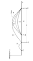
ステップ402では、ワイパブレード30、32の反転位置に応じて基本テーブルの幅を補正する。図5は、ウィンドシールドガラス12上の障害物の影響等により、ワイパブレード30、32が下反転位置P2の手前の反転位置P4で反転する場合に、基本テーブルである上下反転位置間目標速度テーブル90の幅を補正して第1補正目標速度テーブル94を算出した場合を示している。
基本テーブルの幅の補正は、例えば、反転位置P4と上反転位置P1との間の出力軸36、38の回転角度の変化量θ1と、下反転位置P2と上反転位置P1との間の出力軸36、38の回転角度の変化量θ0との商である補正比K1を下記の式(1)のように算出する。算出した補正比K1により、上下反転位置間目標速度テーブル90を横軸方向に伸縮処理して第1補正目標速度テーブル94を算出し、第1補正目標速度テーブル94を反転位置P4と上反転位置P1との間に適用する。
K1=θ1/θ0 ・・・(1)
K1=θ1/θ0 ・・・(1)
後述するように、上下反転位置間目標速度テーブル90及び格納位置下反転位置間目標速度テーブル92の各々は、目標回転速度が、連続した値ではなく、離散的な有限個の値で定められたものである。ステップ402での伸縮処理は、種々の方法が考えられるが、上下反転位置間目標速度テーブル90及び格納位置下反転位置間目標速度テーブル92が離散的な有限個の値の集合であるならば、隣接する値の横軸上での間隔(角度)に、上述の補正比K1を乗算することにより、上下反転位置間目標速度テーブル90及び格納位置下反転位置間目標速度テーブル92の横軸上での伸縮処理を行う。
図5では、横軸上での伸縮処理がされた上下反転位置間目標速度テーブル90を、反転位置P4と上反転位置P1との間に適用することにより、第1補正目標速度テーブル94を生成している。より具体的には、横軸上での伸縮処理がされた上下反転位置間目標速度テーブル90の各値を、反転位置P4から上反転位置P1にプロットすることで、第1補正目標速度テーブル94を算出する。
ステップ404では、反転位置P4に応じた目標回転速度の最大値を算出する。図6は、第1補正目標速度テーブル94の最大値を反転位置P4の位置に応じて補正した第2補正目標速度テーブル96の一例を示している。ステップ404では、補正比K1を第1補正目標速度テーブル94の最大値を含む目標回転速度の各値に乗算することにより、最大値を含む各値が反転位置P4に応じて補正された第2補正目標速度テーブル96を算出する。
ステップ406では、第2補正目標速度テーブル96の目標回転速度の各値の間を直線補間する。図7は、直線補間の一例を示した概略図である。本実施形態では基本テーブルである上下反転位置間目標速度テーブル90は、目標回転速度を連続した値ではなく、離散的な値で保持している。第2補正目標速度テーブル96は、前述のように基本テーブルである上下反転位置間目標速度テーブル90に基づくものなので、第2補正目標速度テーブル96も同様に目標回転速度を有限個の離散的な値で保持している。上下反転位置間目標速度テーブル90及び第2補正目標速度テーブル96が各々保持する有限個の数値の個数は、一例として20~100程度であるが、具体的な個数は、ワイパ装置100の仕様等に応じて決定する。
目標回転速度が離散的に定められたテーブルに従ってワイパモータ18、20の回転を制御すると、1の目標回転速度に従った制御から次の目標回転速度に従った制御に切り替わる際に、ワイパモータ18、20の回転が不整となるおそれがある。従って、本実施形態では、図7に示した直線補間により、第2補正目標速度テーブル96で離散的に定められている目標速度の各値の間を補間する。
ステップ408では、要求払拭速度に応じた目標回転速度の補正を行う。車両用ワイパ装置では、多く場合、ワイパブレードの払拭速度を、高速なHI作動と、低速なLO作動と、に切り換えるようになっている。さらには、ワイパブレードの払拭速度を、LO作動時の払拭速度と、HI作動時の払拭速度と、の間で任意に設定可能な場合もある。
図8は、要求払拭速度とマップ係数との対応の一例を示したグラフであり、LO作動時の払拭速度とHI作動時の払拭速度との間で任意の払拭速度が要求払拭速度として指定された場合を示している。ステップ408では、指定された要求払拭速度に対応するマップ係数を、第2補正目標速度テーブル96の各値に乗算することにより、要求払拭速度に応じた第3補正目標速度テーブル98を算出する。
図9は、第3補正目標速度テーブル98の一例を示した概略図である。図9に示したように、第3補正目標速度テーブル98が示す目標回転速度は、第2補正目標速度テーブル96が示す目標回転速度よりも低速である。図9は、0以上1以下のマップ係数が第2補正目標速度テーブル96の各値に乗算された場合である。ワイパブレード30、32の払拭速度を第2補正目標速度テーブル96の場合よりも高速にするには、1以上のマップ係数を第2補正目標速度テーブル96の各値に乗算する。
以上、図3~9を用いて上下反転位置間目標速度テーブル90から反転位置P4及び要求払拭速度に応じた第3補正目標速度テーブル98を算出する場合を説明した。本実施形態では、反転位置に応じて基本テーブルである上下反転位置間目標速度テーブル90を補正することにより、反転位置に応じた回転速度となるようにワイパモータ18、20を制御する。従って、下反転位置P2、上反転位置P1とは異なる位置からワイパブレード30、32を反転させる又は移動を開始させる場合に、ワイパモータ18、20の出力軸36、38の回転速度が急激に変化することを防止して、ワイパモータ18、20の回転速度を円滑に制御できる。その結果、ワイパブレード30、32の払拭速度を円滑に変化させることが可能となる。
また、本実施形態では、反転位置に応じて補正した目標速度テーブルを、さらに要求払拭速度に応じて補正することにより、要求払拭速度に応じて定めた目標速度テーブルを予め記憶することを要しない。メモリ54に記憶しておく目標速度テーブルは、基本テーブルである上下反転位置間目標速度テーブル90である。コンシールドタイプのワイパ装置の場合には、さらに格納位置P3と下反転位置P2との間のワイパモータ18、20の目標回転速度を定めた格納位置下反転位置間目標速度テーブル92をメモリ54に記憶しておけばよい。
従って、メモリ54に予め記憶しておく目標速度テーブルは、上下反転位置間目標速度テーブル90と格納位置下反転位置間目標速度テーブル92とで足りる。その結果、ワイパ装置の記憶装置の容量を、要求払拭速度に応じて複数記憶する場合よりも抑制でき、製品の生産コスト削減を図ることができる。
以上、ワイパブレード30、32が下反転位置P2の手前(上反転位置P1側から手前)の位置で反転等により動作を開始した場合を説明した。本実施形態では、ワイパブレード30、32が下反転位置P2と格納位置P3との間で反転等により動作を開始した場合に、基本テーブルである上下反転位置間目標速度テーブル90を補正することにより、ワイパモータ18、20の回転速度を円滑に制御する。
図10は、ワイパブレード30、32が格納位置P3から動作を開始した場合の第4補正目標速度テーブル102の一例を示した概略図である。第4補正目標速度テーブル102の算出の手順も、上述の第3補正目標速度テーブル98の場合と同様である。すなわち、上下反転位置間目標速度テーブル90の幅を、下記の式(2)で算出した補正比K2を用いて格納位置P3に応じて補正する。
K2=θ2/θ0 ・・・(2)
K2=θ2/θ0 ・・・(2)
次に、補正比K2を、幅を格納位置P3に応じて補正した目標速度テーブルの目標回転速度の最大値を含む各値に乗算することにより、最大値Vmaxを格納位置P3に応じてVmax2に補正した第4補正目標速度テーブル102を算出する。算出された第4補正目標速度テーブル102は、ワイパブレード30、32を格納位置P3から上反転位置P1に移動させる場合のみならず、ワイパブレード30、32を上反転位置P1から格納位置P3に移動させる場合にも適用できる。
さらに要求払拭速度を変更する場合には、要求払拭速度に応じたマップ係数を第4補正目標速度テーブル102の各値に乗算することにより、ワイパモータ18、20の回転速度に必要な目標速度テーブルを算出する。
以上説明したように、本実施形態では、反転位置又はワイパブレードが動作を開始した位置に応じて基本テーブルを補正することにより、反転位置又は動作を開始した位置に応じた回転速度となるようにワイパモータ18、20を制御する。従って、下反転位置P2、上反転位置P1とは異なる位置からワイパブレード30、32を反転させる又は移動を開始させる場合に、ワイパモータ18、20の出力軸36、38の回転速度が急激に変化することを防止して、ワイパモータ18、20の回転速度を円滑に制御できる。その結果、ワイパブレード30、32の払拭速度を円滑に変化させることが可能となる。
なお、本実施形態に係るワイパ制御装置10は、リンク機構を有しないタンデム式ワイパ装置100以外にも、リンク機構を有するワイパ装置に用いてもよい。
また、本発明は、上記に限定されるものでなく、上記以外にも、その主旨を逸脱しない範囲内において種々変形して実施可能であることは勿論である。
2016年2月1日に出願された日本国特許出願2016-017134号の開示は、その全体が参照により本明細書に取り込まれる。
Claims (5)
- ワイパブレードを一方の所定位置と他方の所定位置との間で移動させる際のワイパモータの目標回転速度を定めた回転速度情報を記憶した記憶部と、
前記ワイパブレードが前記一方の所定位置及び前記他方の所定位置とは異なる動作開始位置から前記一方の所定位置及び前記他方の所定位置のいずれかを次の移動先として動作を開始する場合に、前記動作開始位置と前記ワイパブレードの次の移動先の位置と、に基づいて前記回転速度情報を補正した補正回転速度情報を用いて前記ワイパモータの回転速度を制御する制御部と、
を含むワイパ制御装置。 - 前記ワイパモータの出力軸の回転角度を検出する回転角度検出部を含み、
前記回転速度情報の前記目標回転速度は、前記出力軸の回転角度に対応させて定められ、
前記制御部は、前記動作開始位置と前記次の移動先との間に対応する回転角度範囲と、前記一方の所定位置と前記他方の所定位置との間に対応する回転角度範囲との比である補正比によって、前記目標回転速度を補正することにより前記補正回転速度情報を求める請求項1記載のワイパ制御装置。 - 前記制御部は、前記回転速度情報の前記一方の所定位置と前記他方の所定位置との間に対応する回転角度範囲に前記補正比を乗算して前記回転速度情報の回転角度範囲を補正し、該回転角度範囲を補正した回転速度情報の目標回転速度に前記補正比を乗算することにより求めた前記補正回転速度情報を前記動作開始位置と前記次の移動先との間に適用して前記ワイパモータの回転速度を制御する請求項2記載のワイパ制御装置。
- 前記制御部は、前記ワイパブレードの移動速度を変更する信号が入力された場合に、前記補正回転速度情報の目標回転速度に、前記移動速度を変更する信号に基づいた係数を乗算してさらに補正した回転速度情報に基づいて前記ワイパモータの回転速度を制御する請求項1~3のいずれか1項記載のワイパ制御装置。
- 前記回転速度情報は、前記目標回転速度が前記ワイパモータの出力軸の回転角度の離散値に対して離散的に定められ、
前記制御部は、前記回転速度情報の前記離散的に定められた目標回転速度の各値の間の回転速度を直線補間によって算出する請求項1~4のいずれか1項記載のワイパ制御装置。
Priority Applications (3)
| Application Number | Priority Date | Filing Date | Title |
|---|---|---|---|
| CN201780008485.0A CN108698564B (zh) | 2016-02-01 | 2017-01-31 | 雨刮器控制装置 |
| DE112017000593.0T DE112017000593T5 (de) | 2016-02-01 | 2017-01-31 | Scheibenwischersteuerungsvorrichtung |
| US16/072,760 US10723320B2 (en) | 2016-02-01 | 2017-01-31 | Wiper control device |
Applications Claiming Priority (2)
| Application Number | Priority Date | Filing Date | Title |
|---|---|---|---|
| JP2016017134A JP6696190B2 (ja) | 2016-02-01 | 2016-02-01 | ワイパ制御装置 |
| JP2016-017134 | 2016-02-01 |
Publications (1)
| Publication Number | Publication Date |
|---|---|
| WO2017135260A1 true WO2017135260A1 (ja) | 2017-08-10 |
Family
ID=59500241
Family Applications (1)
| Application Number | Title | Priority Date | Filing Date |
|---|---|---|---|
| PCT/JP2017/003458 Ceased WO2017135260A1 (ja) | 2016-02-01 | 2017-01-31 | ワイパ制御装置 |
Country Status (5)
| Country | Link |
|---|---|
| US (1) | US10723320B2 (ja) |
| JP (1) | JP6696190B2 (ja) |
| CN (1) | CN108698564B (ja) |
| DE (1) | DE112017000593T5 (ja) |
| WO (1) | WO2017135260A1 (ja) |
Cited By (1)
| Publication number | Priority date | Publication date | Assignee | Title |
|---|---|---|---|---|
| JP2017144828A (ja) * | 2016-02-16 | 2017-08-24 | アスモ株式会社 | ワイパ制御装置 |
Families Citing this family (4)
| Publication number | Priority date | Publication date | Assignee | Title |
|---|---|---|---|---|
| US11420594B2 (en) | 2017-08-28 | 2022-08-23 | Rosemount Aerospace Inc. | Configurable variable sweep variable speed wiper system |
| CN110112961A (zh) * | 2019-05-08 | 2019-08-09 | 上海禹点电子科技有限公司 | 一种雨刮的调速控制方法、调速控制系统及调速控制器 |
| CN111361528A (zh) * | 2020-04-27 | 2020-07-03 | 浙江宏博汽配有限公司 | 一种智能雨刷电机的控制系统 |
| US12240300B2 (en) | 2021-01-12 | 2025-03-04 | Henniges Automotive Sealing Systems North America, Inc. | Below belt seal assembly, associated window sealing system, and method for manufacturing same |
Citations (4)
| Publication number | Priority date | Publication date | Assignee | Title |
|---|---|---|---|---|
| JP2011218998A (ja) * | 2010-04-12 | 2011-11-04 | Mitsuba Corp | ワイパ制御装置及びワイパ装置制御方法 |
| WO2013005591A1 (ja) * | 2011-07-06 | 2013-01-10 | 株式会社ミツバ | モータ制御装置 |
| JP2015006809A (ja) * | 2013-06-24 | 2015-01-15 | アスモ株式会社 | ワイパ制御装置 |
| JP2015168273A (ja) * | 2014-03-04 | 2015-09-28 | アスモ株式会社 | ワイパ制御装置 |
Family Cites Families (16)
| Publication number | Priority date | Publication date | Assignee | Title |
|---|---|---|---|---|
| US4339698A (en) * | 1979-04-12 | 1982-07-13 | Kearns Robert W | Control apparatus for windshield wiper system |
| US4866357A (en) * | 1988-12-19 | 1989-09-12 | Ford Motor Company | Windshield wiper and control system |
| DE19700457C1 (de) * | 1997-01-09 | 1998-02-12 | Bosch Gmbh Robert | Vorrichtung und Verfahren für eine Scheibenwischanlage |
| DE19732520A1 (de) * | 1997-07-29 | 1999-02-04 | Itt Mfg Enterprises Inc | Scheibenwischvorrichtung |
| WO2004054856A1 (ja) * | 2002-12-13 | 2004-07-01 | Mitsuba Corporation | ワイパ装置制御方法及びワイパ装置並びに減速機構付きモータ |
| DE102005013591A1 (de) * | 2005-03-24 | 2006-09-28 | Robert Bosch Gmbh | Scheibenwischeranlage mit zwei gegenläufigen Wischern und zwei Reversiermotoren |
| DE102006061679B4 (de) * | 2006-12-28 | 2019-06-19 | Robert Bosch Gmbh | Vorrichtung und Verfahren zur Ansteuerung einer Antriebseinheit einer Wischanlage |
| JP5186468B2 (ja) * | 2009-01-09 | 2013-04-17 | アスモ株式会社 | ワイパ装置、ワイパ制御方法、及びワイパ制御プログラム |
| CN102053561B (zh) * | 2010-12-10 | 2013-01-23 | 上海理工大学 | 基于模糊控制的智能雨刷控制器 |
| US9184689B2 (en) * | 2011-07-06 | 2015-11-10 | Mitsuba Corporation | Motor control device |
| JP5840048B2 (ja) * | 2012-03-26 | 2016-01-06 | アスモ株式会社 | ワイパ装置 |
| US9031390B2 (en) * | 2012-03-26 | 2015-05-12 | Asmo Co., Ltd. | Wiper device |
| JP6077771B2 (ja) * | 2012-07-10 | 2017-02-08 | アスモ株式会社 | ワイパ装置 |
| EP2873568B1 (en) * | 2012-07-12 | 2020-05-06 | Mitsuba Corporation | Wiper control method and wiper control device |
| JP6334856B2 (ja) | 2013-07-04 | 2018-05-30 | 株式会社ミツバ | モータ制御方法及びモータ制御装置 |
| JP6356507B2 (ja) | 2014-07-08 | 2018-07-11 | 日本ポリエチレン株式会社 | オレフィン重合触媒及びオレフィン重合体の製造方法 |
-
2016
- 2016-02-01 JP JP2016017134A patent/JP6696190B2/ja active Active
-
2017
- 2017-01-31 US US16/072,760 patent/US10723320B2/en active Active
- 2017-01-31 WO PCT/JP2017/003458 patent/WO2017135260A1/ja not_active Ceased
- 2017-01-31 DE DE112017000593.0T patent/DE112017000593T5/de active Pending
- 2017-01-31 CN CN201780008485.0A patent/CN108698564B/zh active Active
Patent Citations (4)
| Publication number | Priority date | Publication date | Assignee | Title |
|---|---|---|---|---|
| JP2011218998A (ja) * | 2010-04-12 | 2011-11-04 | Mitsuba Corp | ワイパ制御装置及びワイパ装置制御方法 |
| WO2013005591A1 (ja) * | 2011-07-06 | 2013-01-10 | 株式会社ミツバ | モータ制御装置 |
| JP2015006809A (ja) * | 2013-06-24 | 2015-01-15 | アスモ株式会社 | ワイパ制御装置 |
| JP2015168273A (ja) * | 2014-03-04 | 2015-09-28 | アスモ株式会社 | ワイパ制御装置 |
Cited By (1)
| Publication number | Priority date | Publication date | Assignee | Title |
|---|---|---|---|---|
| JP2017144828A (ja) * | 2016-02-16 | 2017-08-24 | アスモ株式会社 | ワイパ制御装置 |
Also Published As
| Publication number | Publication date |
|---|---|
| US20190061695A1 (en) | 2019-02-28 |
| JP2017136880A (ja) | 2017-08-10 |
| CN108698564B (zh) | 2021-08-17 |
| DE112017000593T5 (de) | 2018-12-13 |
| US10723320B2 (en) | 2020-07-28 |
| JP6696190B2 (ja) | 2020-05-20 |
| CN108698564A (zh) | 2018-10-23 |
Similar Documents
| Publication | Publication Date | Title |
|---|---|---|
| JP6528398B2 (ja) | ワイパ制御装置 | |
| WO2017135260A1 (ja) | ワイパ制御装置 | |
| JP6583042B2 (ja) | ワイパ制御装置 | |
| JP2019193536A (ja) | ワイパ制御装置 | |
| JP6852587B2 (ja) | 車両用ワイパ装置 | |
| JP6593215B2 (ja) | ワイパ制御装置 | |
| JP6294138B2 (ja) | ワイパ制御装置 | |
| US11014538B2 (en) | Wiper device | |
| JP6809283B2 (ja) | ワイパ装置 | |
| JP7435912B2 (ja) | 車両用ワイパ装置及び車両用ワイパ装置の制御方法 | |
| US8897970B2 (en) | Wiper control device and wiper control method | |
| JP6962254B2 (ja) | ワイパ制御装置 | |
| JP7014002B2 (ja) | ワイパ装置及びワイパ装置の制御方法 | |
| EP3624329B1 (en) | Brushless motor, method for controlling the same and method for controlling wiper device | |
| JP6798272B2 (ja) | ワイパ装置 | |
| JP2018131063A (ja) | ワイパ装置 | |
| JP2019209915A (ja) | ワイパ装置及びワイパ装置の制御方法 | |
| JP6805790B2 (ja) | ワイパ装置 | |
| JP2018086959A (ja) | ワイパ装置 |
Legal Events
| Date | Code | Title | Description |
|---|---|---|---|
| 121 | Ep: the epo has been informed by wipo that ep was designated in this application |
Ref document number: 17747416 Country of ref document: EP Kind code of ref document: A1 |
|
| 122 | Ep: pct application non-entry in european phase |
Ref document number: 17747416 Country of ref document: EP Kind code of ref document: A1 |