WO2017134960A1 - 内燃機関制御装置 - Google Patents
内燃機関制御装置 Download PDFInfo
- Publication number
- WO2017134960A1 WO2017134960A1 PCT/JP2016/088611 JP2016088611W WO2017134960A1 WO 2017134960 A1 WO2017134960 A1 WO 2017134960A1 JP 2016088611 W JP2016088611 W JP 2016088611W WO 2017134960 A1 WO2017134960 A1 WO 2017134960A1
- Authority
- WO
- WIPO (PCT)
- Prior art keywords
- temperature
- internal combustion
- combustion engine
- temperature sensor
- control device
- Prior art date
- Legal status (The legal status is an assumption and is not a legal conclusion. Google has not performed a legal analysis and makes no representation as to the accuracy of the status listed.)
- Ceased
Links
Images


Classifications
-
- F—MECHANICAL ENGINEERING; LIGHTING; HEATING; WEAPONS; BLASTING
- F02—COMBUSTION ENGINES; HOT-GAS OR COMBUSTION-PRODUCT ENGINE PLANTS
- F02D—CONTROLLING COMBUSTION ENGINES
- F02D29/00—Controlling engines, such controlling being peculiar to the devices driven thereby, the devices being other than parts or accessories essential to engine operation, e.g. controlling of engines by signals external thereto
-
- F—MECHANICAL ENGINEERING; LIGHTING; HEATING; WEAPONS; BLASTING
- F02—COMBUSTION ENGINES; HOT-GAS OR COMBUSTION-PRODUCT ENGINE PLANTS
- F02D—CONTROLLING COMBUSTION ENGINES
- F02D35/00—Controlling engines, dependent on conditions exterior or interior to engines, not otherwise provided for
-
- F—MECHANICAL ENGINEERING; LIGHTING; HEATING; WEAPONS; BLASTING
- F02—COMBUSTION ENGINES; HOT-GAS OR COMBUSTION-PRODUCT ENGINE PLANTS
- F02D—CONTROLLING COMBUSTION ENGINES
- F02D41/00—Electrical control of supply of combustible mixture or its constituents
- F02D41/02—Circuit arrangements for generating control signals
- F02D41/04—Introducing corrections for particular operating conditions
-
- F—MECHANICAL ENGINEERING; LIGHTING; HEATING; WEAPONS; BLASTING
- F02—COMBUSTION ENGINES; HOT-GAS OR COMBUSTION-PRODUCT ENGINE PLANTS
- F02D—CONTROLLING COMBUSTION ENGINES
- F02D45/00—Electrical control not provided for in groups F02D41/00 - F02D43/00
Definitions
- the present invention relates to an internal combustion engine control device, and more particularly to an internal combustion engine control device applied to a general-purpose internal combustion engine such as a generator or a vehicle such as a motorcycle.
- a temperature sensor in a fuel injection system is generally used for detecting a warm-up state of an internal combustion engine. More specifically, the fuel injection system calculates the temperature of the internal combustion engine based on the output of the temperature sensor, detects the warm-up state of the internal combustion engine based on the calculated temperature of the internal combustion engine, and determines the ignition timing. And control of fuel injection. For this reason, when adopting a fuel injection system, it is necessary to attach a temperature sensor to the internal combustion engine. Furthermore, when installing a temperature sensor in the internal combustion engine, it is necessary to install wires and couplers for wiring, and it is necessary to process the part of the internal combustion engine in which the temperature sensor is installed.
- the ratio of the cost of the fuel injection system to the sales price is higher than that of the carburetor system.
- a temperature sensor is required to be omitted from the fuel injection system for the purpose of cost reduction.
- a temperature sensor such as an intake air temperature sensor
- a backup temperature sensor is provided in preparation for a case where a malfunction occurs in the temperature sensor and the atmospheric temperature of the internal combustion engine cannot be detected. It is also preferable.
- Patent Document 1 relates to the electronic control device 1, and the temperature detection means 10 such as a resistance temperature detector, thermistor, thermocouple, etc., is substantially isothermal with the surface temperature T 0 of the storage portion 34 on the mounting surface side of the substrate 30. Or a range BL (H) of a predetermined distance W from the outer peripheral edge of the substrate 30 which is a mounting position where the temperature difference (T2 ⁇ T0) with the surface temperature of the storage portion 34 falls within the predetermined range ⁇ t. ) And outside the range (RHT) of a predetermined distance from the semiconductor switching element 20 is disclosed.
- the temperature detection means 10 such as a resistance temperature detector, thermistor, thermocouple, etc.
- the present invention has been made through the above-described studies, and it is possible to omit a temperature sensor outside the apparatus, such as an intake air temperature sensor.
- An object of the present invention is to provide an internal combustion engine control device capable of calculating the atmospheric temperature of an internal combustion engine with high accuracy.
- the present invention provides an internal combustion engine control apparatus that controls an operating state of the internal combustion engine based on an ambient temperature of the internal combustion engine, wherein the internal combustion engine control apparatus includes a first temperature sensor and a first temperature. A second temperature sensor disposed at a position spaced apart from the sensor, wherein the control unit determines a detected temperature of one of the first temperature sensor and the second temperature sensor as the first temperature sensor and the second temperature sensor; It is a first aspect to calculate the ambient temperature around the internal combustion engine control device by correcting with the other detected temperature of the temperature sensor, and to control the internal combustion engine based on the ambient temperature.
- the present invention provides the control unit, a temperature difference between the detected temperature of the first temperature sensor and the detected temperature of the second temperature sensor, the first temperature sensor, and the first temperature sensor.
- the detected temperature of the first temperature sensor and the detected temperature of the second temperature sensor using a correlation characteristic that defines the relationship between the difference between the detected temperature of the one temperature sensor and the ambient temperature.
- the second aspect is to calculate the ambient temperature from the difference temperature.
- the internal combustion engine is mounted on a vehicle, and the control unit includes the correlation characteristic for the operation period of the internal combustion engine and the correlation characteristic for the stop period of the internal combustion engine.
- the third aspect is to use.
- the one of the first temperature sensor and the second temperature sensor is provided in the vicinity of a housing of the internal combustion engine control device, and the first temperature sensor
- the fourth aspect is that the other of the second temperature sensors is provided in the vicinity of the heating element housed in the housing.
- the internal combustion engine control apparatus further includes the first temperature sensor and the second temperature sensor disposed at a position spaced apart from the first temperature sensor, and the control unit.
- the ambient temperature around the internal combustion engine control device is calculated by correcting the detected temperature of one of the first temperature sensor and the second temperature sensor with the detected temperature of the other of the first temperature sensor and the second temperature sensor. Since the internal combustion engine is controlled based on the temperature, it is possible to omit a temperature sensor outside the apparatus such as an intake air temperature sensor, and with a simple configuration, the overall cost can be suppressed, and the practically sufficient accuracy can be achieved.
- the atmospheric temperature of the internal combustion engine can be calculated.
- the control unit includes the difference temperature between the detected temperature of the first temperature sensor and the detected temperature of the second temperature sensor, the first temperature sensor, and the first temperature sensor.
- the ambient temperature is calculated from the difference temperature between the detected temperature of the first temperature sensor and the detected temperature of the second temperature sensor, using a correlation characteristic that defines the relationship between the detected temperature of one of the two temperature sensors and the ambient temperature.
- the detected temperature of one of the first temperature sensor and the second temperature sensor can be easily corrected with the detected temperature of the other of the first temperature sensor and the second temperature sensor, and the intake air temperature sensor It is possible to omit the temperature sensor outside the apparatus and the like, and the atmospheric temperature of the internal combustion engine can be calculated with practically sufficient accuracy while suppressing the overall cost with a simple configuration.
- the internal combustion engine is mounted on the vehicle, and the control unit is used for the correlation characteristic for the operation period of the internal combustion engine and for the stop period of the internal combustion engine of the vehicle. Therefore, it is possible to use a correlation characteristic that well reflects the temperature characteristics resulting from the difference in the heat generation state of the internal combustion engine and the difference in the heat generation state of the components of the internal combustion engine control device.
- the temperature sensor outside the apparatus such as a sensor can be omitted, and the atmospheric temperature of the internal combustion engine can be calculated with practically sufficient accuracy while suppressing the overall cost with a simple configuration.
- one of the first temperature sensor and the second temperature sensor is provided in the vicinity of the housing of the internal combustion engine control device, and the first temperature sensor and Since the other of the second temperature sensors is provided close to the heating element housed in the housing, it is possible to calculate an ambient temperature having good consistency with the actual ambient temperature of the internal combustion engine with good reproducibility. Further, it is possible to omit the temperature sensor outside the apparatus such as the intake air temperature sensor, and the atmospheric temperature of the internal combustion engine can be calculated with practically sufficient accuracy while suppressing the overall cost with a simple configuration.
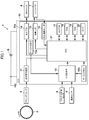
- FIG. 1 is a schematic diagram showing a configuration of an internal combustion engine control apparatus according to an embodiment of the present invention.
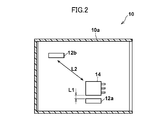
- FIG. 2 is a schematic cross-sectional view showing an arrangement position of the thermistor element in the internal combustion engine control apparatus shown in FIG.
- FIG. 3A is a diagram showing temporal changes in the detected temperature of the thermistor element of the internal combustion engine controller and the atmospheric temperature of the internal combustion engine in the present embodiment.
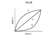
- FIG. 3B is a diagram illustrating a correlation characteristic line that defines the relationship between the first differential temperature and the second differential temperature that are referred to by the internal combustion engine control apparatus according to the present embodiment.
- FIG. 4 is a flowchart showing the flow of the atmospheric temperature calculation process of the internal combustion engine controller according to this embodiment.
- the internal combustion engine control device in the present embodiment is typically suitably mounted on an internal combustion engine mounting body such as a general-purpose machine such as a generator or a vehicle such as a motorcycle.
- the internal combustion engine control device will be described as being mounted on a vehicle such as a motorcycle.
- FIG. 1 is a schematic diagram showing a configuration of an internal combustion engine control apparatus according to the present embodiment.
- an internal combustion engine control device 1 controls an operating state of an engine based on an ambient temperature of an engine that is an internal combustion engine such as a gasoline engine mounted on a vehicle (not shown). And an electronic control unit (Electronic Control Unit: ECU) 10 is provided.
- ECU Electronic Control Unit
- the ECU 10 operates by using electric power from the battery B mounted on the vehicle, and includes a waveform shaping circuit 11, the thermistor elements 12a and 12b, an A / D converter 13, an ignition circuit 14, a drive circuit 15, and a resistor.
- Value detection circuit 16 EEPROM (Electrically Erasable Programmable Read-Only Memory) 17, ROM (Read-Only Memory) 18, RAM (Random Access Memory) 19, Timer 20, and Central Processing Unit (Central CPU 21)
- Each component of the ECU 10 is accommodated in a casing 10a of the ECU 10.
- the ECU 10 and the surroundings of the engine are in contact with the outside air, and the ECU 10 is arranged away from the engine so as not to be affected by the radiant heat of the engine and the heat transfer from the engine. is there.
- the waveform shaping circuit 11 shapes a crank pulse signal corresponding to the rotation angle of the crankshaft 3 of the engine output from the crank angle sensor 2 to generate a digital pulse signal.
- the waveform shaping circuit 11 outputs the digital pulse signal thus generated to the CPU 21.
- the thermistor element 12a (thermistor B) is located in the region of the ECU 10 having the highest temperature in the casing 10a (typically a region close to the heating element whose distance to the heating element as the ignition circuit 14 is about several millimeters).
- the chip thermistor is arranged and exhibits an electrical resistance value corresponding to the temperature, and outputs an electrical signal indicating a voltage corresponding to the electrical resistance value to the A / D converter 13.
- the thermistor element 12a may be replaced with another temperature sensor such as a thermocouple as long as such an electrical signal can be output.
- the thermistor element 12b (thermistor A) is an ambient temperature (outside temperature) that is the ambient temperature outside the casing 10a of the ECU 10 in the casing 10a of the ECU 10, that is, an ambient temperature (outside temperature) that is the ambient temperature around the engine.
- a chip thermistor placed in a region close to (temperature) (typically a region close to the housing 10a whose distance to the housing 10a is about several millimeters), and exhibits an electrical resistance value corresponding to the temperature.
- the electric signal indicating the voltage corresponding to the electric resistance value is output to the A / D converter 13.
- the thermistor element 12b may be replaced with another temperature sensor such as a thermocouple as long as it can output such an electrical signal.
- the A / D converter 13 is an electric signal indicating the opening degree of the throttle valve of the engine output from the throttle opening degree sensor 4 and an electric signal indicating the oxygen concentration in the atmosphere sucked into the engine output from the oxygen sensor 5.
- the electrical signals output from the thermistor elements 12a and 12b are converted from an analog form to a digital form, respectively.
- the A / D converter 13 outputs these electrical signals thus converted into digital form to the CPU 21.
- the ignition circuit 14 includes a switching element such as a transistor that is controlled to be turned on / off in accordance with a control signal from the CPU 21. When the switching element is turned on / off, the fuel in the engine is passed through a spark plug (not shown). And the operation of the ignition coil 6 for generating a secondary voltage for igniting the air-fuel mixture.
- the ignition circuit 14 is typically a driver IC (Integrated Circuit) that is a semiconductor element, and is a component that generates the largest amount of heat in the housing 10a.
- the drive circuit 15 includes a switching element such as a transistor that is controlled to be turned on / off in accordance with a control signal from the CPU 21, and the switching element is turned on / off to energize / coil the coil of the injector 7 that supplies fuel to the engine. Switch the non-energized state.
- the injector 7 is attached to an intake pipe or a cylinder head (not shown) of the engine, and heat generated from the engine is transferred.
- the equivalent circuit of the coil of the injector 7 is represented by a series circuit composed of an inductance component and an electric resistance component.
- the resistance value detection circuit 16 measures an electrical resistance value (resistance value) that is a physical quantity that varies depending on the electrical resistance component of the coil of the injector 7, and outputs an electrical signal indicating the measured resistance value to the CPU 21. To do.
- the injector temperature corresponding to the resistance value of the coil of the injector 7 can be used as the engine temperature (engine temperature), but the engine temperature is obtained by another temperature sensor such as an intake air temperature sensor. Therefore, it is not necessary to measure the resistance value of the coil of the injector 7, and correspondingly, the resistance value detection circuit 16 is also unnecessary.
- the EEPROM 17 stores data relating to various learning values such as a fuel injection amount learning value and a throttle reference position learning value. Note that the EEPROM 17 may be replaced with another storage medium such as a data flash as long as it can store data relating to such various learning values.
- the ROM 18 is configured by a non-volatile storage device, and stores various control data such as a control program for an atmospheric temperature calculation process, which will be described later, and table data representing a correlation characteristic line used in the atmospheric temperature calculation process.
- the RAM 19 is composed of a volatile storage device and functions as a working area for the CPU 21.
- the timer 20 performs a time measurement process according to a control signal from the CPU 21.
- the CPU21 controls the operation of the entire ECU10.
- the CPU 21 executes an ambient temperature calculation process control program stored in the ROM 18, so that the ambient temperature (outside air temperature) that is the ambient ambient temperature outside the casing 10 a of the ECU 10, that is, The operating temperature of the engine is controlled by calculating the ambient temperature (outside temperature), which is the ambient air temperature around the engine, and controlling the ignition circuit 14 and the drive circuit 15 based on the calculated ambient temperature of the engine. .
- FIG. 2 is a schematic cross-sectional view showing the arrangement position of the thermistor element in the internal combustion engine control apparatus shown in FIG.
- the thermistor elements 12 a and 12 b and the ignition circuit 14 are disposed in a housing 10 a that houses each component of the ECU 10.
- the ignition circuit 14 is typically a driver IC and is a component that generates the largest amount of heat in the housing 10a.
- the thermistor element 12a is disposed at a first arrangement position close to the ignition circuit 14 having the largest calorific value within the housing 10a so as to be the distance L1, and the thermistor element 12b is The distance L2 (>> L1) with respect to the second arrangement position farther from the ignition circuit 14 than the first arrangement position.
- the thermistor element 12a is arranged at the position where it is most directly affected by the heat generation of the ignition circuit 14 and becomes the highest temperature in the housing 10a, and the thermistor element 12b is affected by the heat generation of the ignition circuit 14. It is disposed at a position where it is least affected and is most affected by the atmospheric temperature outside the casing 10a close to the casing 10a (the atmospheric temperature of the ECU 10 and corresponding to the atmospheric temperature of the engine).
- the internal combustion engine control device 1 having such a configuration can omit the temperature sensor outside the device, such as an intake air temperature sensor, by executing the following atmospheric temperature calculation process.
- the engine ambient temperature is calculated with sufficient accuracy while keeping costs down.
- the operation of the internal combustion engine control apparatus 1 when executing the atmospheric temperature calculation process in the present embodiment will be described more specifically with reference to FIG. 3 and FIG. 4 as well.
- FIG. 3A is a diagram showing temporal changes in the detected temperature T1 of the thermistor element 12a, the detected temperature T2 of the thermistor element 12b, and the ambient temperature Ta of the engine of the internal combustion engine control apparatus 1 according to the present embodiment. It is a figure which shows the correlation characteristic line which prescribed
- DELTA 1st difference temperature
- DELTA 2nd difference temperature
- the atmosphere is determined based on the first differential temperature ⁇ T12 obtained by subtracting the detection temperature T2 of the thermistor element 12b from the detection temperature T1 of the thermistor element 12a, and the detection temperature T2 of the thermistor element 12b.
- Table data indicating a correlation characteristic line in which a relationship with the second differential temperature ⁇ T2a obtained by subtracting the temperature Ta is previously stored in the ROM 18 is prepared.
- FIG. 3A shows an example of the change over time of the detected temperature T1 of the thermistor element 12a, the detected temperature T2 of the thermistor element 12b, and the engine ambient temperature Ta calculated by the ambient temperature calculation process in the present embodiment.
- the first differential temperature ⁇ T12 basically corresponds to the amount of heat generated by the ignition circuit 14, that is, the amount of heat generated by the ECU 10.
- the second differential temperature ⁇ T2a is determined based on the detected temperature T2 of the thermistor element 12b in consideration of the fact that the detected temperature T2 of the thermistor element 12b may differ from the engine ambient temperature Ta due to the influence of the amount of heat generated by the ignition circuit 14, etc. This corresponds to the temperature difference between T2 and the engine ambient temperature Ta.
- a first differential temperature ⁇ T12 obtained by subtracting the detected temperature T2 of the thermistor element 12b from the detected temperature T1 of the thermistor element 12a
- a second differential temperature ⁇ T2a obtained by subtracting the ambient temperature Ta from the detected temperature T2 of the thermistor element 12b
- the correlation characteristic line that defines the relationship of “a” is shared when the engine is operating (when the engine is operating: non-est) and when the engine is stopped (when the engine is stopped: when it is stalled). It may be a line, or may be a b line and a c line to which hysteresis is given at the time of non-engine stall and at engine stall.
- the common a line at the time of non-end and at the end is not limited to a straight line and may be a curved line as necessary.
- the non-end time b line may have a characteristic that its inclination increases with the passage of time so as to reflect a temperature change caused by a heat generation state in the engine or the internal combustion engine control device 1 at the time of non-end time.
- the engine stall c line has a characteristic that its inclination decreases with the passage of time so as to reflect a temperature change caused by a heat generation state in the engine or the internal combustion engine control device 1 at the engine stall time.
- such correlation characteristic lines are obtained by plotting their respective values in order and smoothly connecting them. In the ambient temperature calculation processing, such correlation characteristic lines may be handled as mathematical expressions. May be treated as a collection of data values.
- the first difference temperature ⁇ T12 is calculated, and the second difference corresponding to the value of the first difference temperature ⁇ T12 is obtained by searching the table data indicating the correlation characteristic line.
- the value of temperature ⁇ T2a is obtained.
- a value obtained by subtracting the second differential temperature ⁇ T2a from the detected temperature T2 of the thermistor element 12b is calculated as the engine ambient temperature Ta.
- the engine ambient temperature Ta calculated by the ambient temperature calculation process in the present embodiment is a value that is in good agreement with the measured value of the engine ambient temperature.
- FIG. 4 is a flowchart showing the flow of the atmospheric temperature calculation process of the internal combustion engine control apparatus according to this embodiment.
- the flowchart shown in FIG. 4 starts when the ignition switch of the vehicle is switched from the off state to the on state and the CPU 21 operates, and the ambient temperature calculation process proceeds to step S1.
- Such atmospheric temperature calculation processing is repeatedly executed at predetermined control cycles while the ignition switch of the vehicle is on and the CPU 21 is operating.
- step S1 the CPU 21 calculates a first difference temperature ⁇ T12 ((B ⁇ A) difference) obtained by subtracting the detection temperature T2 of the thermistor element 12b (thermistor A) from the detection temperature T1 of the thermistor element 12a (thermistor B). calculate. Thereby, the process of step S1 is completed and the ambient temperature calculation process proceeds to the process of step S2.
- step S2 the CPU 21 determines whether or not the vehicle is stalled based on the electrical signal output from the crank angle sensor 2. If the result of determination is that the vehicle is stalled, the CPU 21 advances the ambient temperature calculation process to the process of step S4. On the other hand, when the vehicle is not stalled, that is, when the vehicle is running, the CPU 21 advances the ambient temperature calculation process to the process of step S3.
- the CPU 21 determines whether or not the merge process has been completed.
- the merging process is a predetermined subtraction amount (second difference temperature ⁇ T2a) from the detected temperature T2 at the time of the stall to a subtraction amount (second difference temperature ⁇ T2a) from the detection temperature T2 at the time of the non-ist.
- step S4 the CPU 21 detects the value of the second differential temperature ⁇ T2a corresponding to the first differential temperature ⁇ T12 calculated in the process of step S1 by searching the table data indicating the correlation characteristic line at the time of the stall. Obtained as a subtraction amount from the temperature T2 (thermistor A subtraction amount). Thereby, the process of step S4 is completed and the ambient temperature calculation process proceeds to the process of step S7.
- step S5 the CPU 21 changes a value obtained by changing the subtraction amount from the detection temperature T2 at the time of the stall to a subtraction amount from the detection temperature T2 at the time of the non-estimation by a predetermined amount (the thermistor). (A subtraction amount).
- step S6 the CPU 21 retrieves the value of the second differential temperature ⁇ T2a corresponding to the first differential temperature ⁇ T12 calculated in the process of step S1 by searching the table data indicating the correlation characteristic line at the time of non-est. Obtained as a subtraction amount (thermistor A subtraction amount) from the detected temperature T2. Thereby, the process of step S6 is completed, and the ambient temperature calculation process proceeds to the process of step S7.
- a subtraction amount thermoistor A subtraction amount
- step S7 the CPU 21 calculates a value obtained by subtracting the thermistor A subtraction amount obtained by the process of any of steps S4 to S7 from the detected temperature T2 of the thermistor element 12b as the engine ambient temperature Ta. Thereby, the process of step S7 is completed and this series of atmosphere temperature calculation processes are complete
- the internal combustion engine control device 1 includes the thermistor element 12a and the thermistor element 12b disposed at a position spaced from the thermistor element 12a.
- the engine ambient temperature is calculated by correcting the detected temperature T2 of the thermistor element 12b with the detected temperature T1 of the thermistor element 12a.
- the type, shape, arrangement, number, and the like of the members are not limited to the above-described embodiment, and the gist of the invention is appropriately replaced such that the constituent elements are appropriately replaced with those having the same operational effects.
- the gist of the invention is appropriately replaced such that the constituent elements are appropriately replaced with those having the same operational effects.
- it can be changed as appropriate without departing from the scope.
- the present invention makes it possible to omit a temperature sensor outside the apparatus, such as an intake air temperature sensor, and suppresses the overall cost with a simple configuration, while maintaining an atmospheric temperature of an internal combustion engine with sufficient practical accuracy.
- An internal combustion engine control device capable of calculating the engine can be provided, and can be widely applied to general-purpose internal combustion engines such as generators and internal combustion engine control devices for vehicles such as motorcycles because of its universal character. Be expected.
Landscapes
- Engineering & Computer Science (AREA)
- Chemical & Material Sciences (AREA)
- Combustion & Propulsion (AREA)
- Mechanical Engineering (AREA)
- General Engineering & Computer Science (AREA)
- Combined Controls Of Internal Combustion Engines (AREA)
- Control Of Vehicle Engines Or Engines For Specific Uses (AREA)
- Electrical Control Of Air Or Fuel Supplied To Internal-Combustion Engine (AREA)
Abstract
内燃機関制御装置(1)は、サーミスタ素子(12a)及びサーミスタ素子(12a)から離間した位置に配設されたサーミスタ素子(12b)を備え、CPU(21)は、サーミスタ素子(12b)の検出温度(T2)をサーミスタ素子(12a)の検出温度(T1)で補正することによりエンジンの雰囲気温度を算出し、エンジンの雰囲気温度に基づいて、エンジンの運転状態を制御する。
Description
本発明は、内燃機関制御装置に関し、特に、発電機等の汎用内燃機関や自動二輪車等の車両に適用される内燃機関制御装置に関する。
近年、発電機等の汎用機や小型自動二輪車等の車両においては、キャブレタシステムでは今後より厳しくなる排気ガス規制に対応することが困難になるため、排気ガスの低減を目的として燃料噴射システムの採用が推進されている。しかしながら、発電機等の汎用機や小型自動二輪車等の車両の販売価格は大型自動二輪車や四輪自動車等の車両の販売と比較して安価であるために、このような販売価格を考えた場合、キャブレタシステムと比較して高コストな燃料噴射システムをそのまま発電機等の汎用機や小型自動二輪車等の車両に採用することは困難である。このため、発電機等の汎用機や小型自動二輪車等の車両においては、燃料噴射システムに関する部品、特にセンサ類については、コストの低減が求められている。
ここで、例えば燃料噴射システムにおける温度センサは、内燃機関の暖機状態の検出のために用いられることが一般的である。具体的には、燃料噴射システムは、温度センサの出力に基づいて内燃機関の温度を算出し、このように算出した内燃機関の温度に基づいて内燃機関の暖機状態を検出して、点火時期及び燃料噴射の制御を行っている。このため、燃料噴射システムを採用する場合には、内燃機関に温度センサを装着する必要がある。更に、内燃機関に温度センサを設置する際には、配線用のワイヤやカプラを設置する必要がある上に、温度センサを設置する内燃機関の部位を加工する必要がある。この結果、販売価格における燃料噴射システムのコストの割合はキャブレタシステムのものと比較して高くなる。このため、特に発電機等の汎用機や小型自動二輪車等の車両において燃料噴射システムを制御する内燃機関制御装置においては、コストダウンを目的として燃料噴射システムから温度センサを省略することが求められている。
併せて、吸気温センサ等の温度センサが設けられる場合であっても、かかる温度センサに不具合が発生し、内燃機関の雰囲気温度を検出できない場合に備えて、何らかのバックアップ用の温度センサが設けられていることも好ましい。
かかる状況下で、特許文献1は、電子制御装置1に関し、測温抵抗体、サーミスタ、熱電対等の温度検出手段10を、基板30の実装面側で、収納部34の表面温度T0と略等温になる載置位置、又は収納部34の表面温度との温度差(T2-T0)が所定の範囲Δt内となる載置位置である基板30の外周縁から所定の距離Wの範囲BL(H)内で、かつ半導体スイッチング素子20から所定の距離の範囲(RHT)外に載置する構成を開示する。
しかしながら、本発明者の検討によれば、特許文献1記載の構成のように電子制御装置の熱影響を受けにくい位置に温度検出手段を配置した場合であっても、電子制御装置自体の温度が上昇した際には、内燃機関の雰囲気温度を精度よく検出できない可能性が考えられる。
本発明は、以上の検討を経てなされたものであり、吸気温センサ等の装置外の温度センサを省略することを可能として、簡素な構成で装置全体のコストを抑制しながら、実用上充分な精度で内燃機関の雰囲気温度を算出可能な内燃機関制御装置を提供することを目的とする。
以上の目的を達成するべく、本発明は、内燃機関の雰囲気温度に基づいて前記内燃機関の運転状態を制御する内燃機関制御装置において、前記内燃機関制御装置は第1温度センサ及び前記第1温度センサから離間した位置に配設された第2温度センサを更に備え、前記制御部は、前記第1温度センサ及び前記第2温度センサの一方の検出温度を、前記第1温度センサ及び前記第2温度センサの他方の検出温度で補正することにより前記内燃機関制御装置周りの雰囲気温度を算出し、前記雰囲気温度に基づいて内燃機関を制御することを第1の局面とする。
本発明は、第1の局面に加えて、前記制御部は、前記第1温度センサの前記検出温度と前記第2温度センサの前記検出温度との差分温度と、前記第1温度センサ及び前記第2温度センサの前記一方の前記検出温度と前記雰囲気温度との差分温度と、の関係を規定した相関特性を用いて、前記第1温度センサの前記検出温度と前記第2温度センサの前記検出温度との前記差分温度から前記雰囲気温度を算出することを第2の局面とする。
本発明は、第2の局面に加えて、前記内燃機関は、車両に搭載され、前記制御部は、前記内燃機関の運転期間用の前記相関特性及び前記内燃機関の停止期間用の前記相関特性を用いることを第3の局面とする。
本発明は、第2又は第3の局面に加えて、前記第1温度センサ及び前記第2温度センサの前記一方は、前記内燃機関制御装置の筺体に近接して設けられ、前記第1温度センサ及び前記第2温度センサの前記他方は、前記筐体内に収容された発熱素子に近接して設けられることを第4の局面とする。
本発明の第1の局面にかかる内燃機関制御装置によれば、内燃機関制御装置は第1温度センサ及び第1温度センサから離間した位置に配設された第2温度センサを更に備え、制御部が、第1温度センサ及び第2温度センサの一方の検出温度を、第1温度センサ及び第2温度センサの他方の検出温度で補正することにより内燃機関制御装置周りの雰囲気温度を算出し、雰囲気温度に基づいて内燃機関を制御するものであるため、吸気温センサ等の装置外の温度センサを省略することを可能として、簡素な構成で全体のコストを抑制しながら、実用上充分な精度で内燃機関の雰囲気温度を算出することができる。
また、本発明の第2の局面にかかる内燃機関制御装置によれば、制御部が、第1温度センサの検出温度と第2温度センサの検出温度との差分温度と、第1温度センサ及び第2温度センサの一方の検出温度と雰囲気温度との差分温度と、の関係を規定した相関特性を用いて、第1温度センサの検出温度と第2温度センサの検出温度との差分温度から雰囲気温度を算出するものであるため、第1温度センサ及び第2温度センサの一方の検出温度を、第1温度センサ及び第2温度センサの他方の検出温度で簡便に補正することができ、吸気温センサ等の装置外の温度センサを省略することを可能として、簡素な構成で全体のコストを抑制しながら、実用上充分な精度で内燃機関の雰囲気温度を算出することができる。
また、本発明の第3の局面にかかる内燃機関制御装置によれば、内燃機関が、車両に搭載され、制御部は、内燃機関の運転期間用の相関特性及び車両の内燃機関の停止期間用の相関特性を用いるものであるため、内燃機関の発熱状態の相違や内燃機関制御装置の構成要素の発熱状態の相違に起因する温度特性を良好に反映する相関特性を用いることができ、吸気温センサ等の装置外の温度センサを省略することを可能として、簡素な構成で全体のコストを抑制しながら、実用上充分な精度で内燃機関の雰囲気温度を算出することができる。
また、本発明の第4の局面にかかる内燃機関制御装置によれば、第1温度センサ及び第2温度センサの一方は、内燃機関制御装置の筺体に近接して設けられ、第1温度センサ及び第2温度センサの他方は、筐体内に収容された発熱素子に近接して設けられるものであるため、内燃機関の現実の雰囲気温度と一致性のよい雰囲気温度を再現性よく算出することができ、吸気温センサ等の装置外の温度センサを省略することを可能として、簡素な構成で全体のコストを抑制しながら、実用上充分な精度で内燃機関の雰囲気温度を算出することができる。
以下、図面を適宜参照して、本発明の実施形態における内燃機関制御装置につき、詳細に説明する。
〔内燃機関制御装置の構成〕
まず、図1を参照して、本実施形態における内燃機関制御装置の構成について説明する。本実施形態における内燃機関制御装置は、典型的には、発電機等の汎用機や自動二輪車等の車両といった内燃機関搭載体に好適に搭載されるものであるが、以下、説明の便宜上、かかる内燃機関制御装置は、自動二輪車等の車両に搭載されるものとして説明する。
まず、図1を参照して、本実施形態における内燃機関制御装置の構成について説明する。本実施形態における内燃機関制御装置は、典型的には、発電機等の汎用機や自動二輪車等の車両といった内燃機関搭載体に好適に搭載されるものであるが、以下、説明の便宜上、かかる内燃機関制御装置は、自動二輪車等の車両に搭載されるものとして説明する。
図1は、本実施形態における内燃機関制御装置の構成を示す模式図である。
図1に示すように、本実施形態における内燃機関制御装置1は、図示を省略する車両に搭載されたガソリンエンジン等の内燃機関であるエンジンの雰囲気温度に基づいてエンジンの運転状態を制御するものであり、電子制御ユニット(Electronic Control Unit:ECU)10を備えている。
ECU10は、車両に搭載されたバッテリBからの電力を利用して動作するものであり、波形整形回路11、サーミスタ素子12a、12b、A/D変換機13、点火回路14、駆動回路15、抵抗値検出回路16、EEPROM(Electrically Erasable Programmable Read-Only Memory)17、ROM(Read-Only Memory)18、RAM(Random Access Memory)19、タイマ20、及び中央処理ユニット(Central Processing Unit:CPU)21を備えている。かかるECU10の各構成要素は、ECU10の筐体10a内に収容される。また、典型的には、ECU10及びエンジンの周囲は、各々外気に触れており、ECU10は、エンジンの放射熱及びエンジンからの伝熱の影響を受けないようにそれから離間して配置されるものである。
波形整形回路11は、クランク角センサ2から出力されたエンジンのクランクシャフト3の回転角に対応するクランクパルス信号を整形してデジタルパルス信号を生成する。波形整形回路11は、このように生成したデジタルパルス信号をCPU21に出力する。
サーミスタ素子12a(サーミスタB)は、ECU10の筐体10a内で最も高温となる領域(典型的には点火回路14である発熱素子への距離が数ミリメータ程度である発熱素子に近接した領域)に配置されたチップサーミスタであり、その温度に対応した電気抵抗値を呈して、その電気抵抗値に応じた電圧を示す電気信号をA/D変換機13に出力する。なお、かかる電気信号を出力可能なものであれば、サーミスタ素子12aを熱電対等の他の温度センサに代替してもよい。
サーミスタ素子12b(サーミスタA)は、ECU10の筐体10a内で最もECU10の筐体10a外の周囲の大気温度である雰囲気温度(外気温)、つまりエンジンの周囲の大気温度である雰囲気温度(外気温)に近くなる領域(典型的には筐体10aへの距離が数ミリメータ程度である筐体10aに近接した領域)に配置されたチップサーミスタであり、その温度に対応した電気抵抗値を呈してその電気抵抗値に応じた電圧を示す電気信号をA/D変換機13に出力する。なお、かかる電気信号を出力可能なものであれば、サーミスタ素子12bを熱電対等の他の温度センサに代替してもよい。
A/D変換機13は、スロットル開度センサ4から出力されたエンジンのスロットルバルブの開度を示す電気信号、酸素センサ5から出力されたエンジンに吸気される大気中の酸素濃度を示す電気信号、及びサーミスタ素子12a、12bから出力された電気信号を、アナログ形態からデジタル形態に各々変換する。A/D変換機13は、このようにデジタル形態に変換したこれらの電気信号をCPU21に出力する。
点火回路14は、CPU21からの制御信号に従ってオン/オフ制御されるトランジスタ等のスイッチング素子を備え、このスイッチング素子がオン/オフ動作することによって、図示を省略する点火プラグを介してエンジン内の燃料及び空気の混合気に点火するための2次電圧を発生する点火コイル6の動作を制御する。また、点火回路14は、典型的には半導体素子であるドライバIC(Integrated Circuit)であり、筐体10a内で発熱量が最も大きい構成要素である。
駆動回路15は、CPU21からの制御信号に従ってオン/オフ制御されるトランジスタ等のスイッチング素子を備え、このスイッチング素子がオン/オフ動作することによって、エンジンに燃料を供給するインジェクタ7のコイルの通電/非通電状態を切り換える。ここで、インジェクタ7は、エンジンの図示を省略する吸気管やシリンダヘッドに装着され、エンジンから生じる熱が伝熱される。また、インジェクタ7のコイルの等価回路は、インダクタンス成分と電気抵抗成分とから成る直列回路で表される。
抵抗値検出回路16は、インジェクタ7のコイルの電気抵抗成分に依存して変動する物理量である電気抵抗値(抵抗値)を測定し、このように測定した抵抗値を示す電気信号をCPU21に出力する。なお、インジェクタ7のコイルの抵抗値に対応するインジェクタ温度は、エンジンの温度(エンジン温度)として用いられ得るものであるが、かかるエンジン温度が、吸気温センサ等の他の温度センサにより求められる場合には、インジェクタ7のコイルの抵抗値の測定は不要となり、これに対応して、抵抗値検出回路16も不要となる。
EEPROM17は、燃料噴射量学習値やスロットル基準位置学習値といった各種学習値に関するデータ等を記憶する。なお、このような各種学習値に関するデータ等を記憶可能なものであれば、EEPROM17をデータフラッシュ等の他の記憶媒体に代替してもよい。
ROM18は、不揮発性の記憶装置によって構成され、後述する雰囲気温度算出処理用等の制御プログラム、及び雰囲気温度算出処理において用いられる相関特性線を呈するテーブルデータ等の各種制御データを格納している。
RAM19は、揮発性の記憶装置によって構成され、CPU21のワーキングエリアとして機能する。
タイマ20は、CPU21からの制御信号に従って計時処理を実行する。
CPU21は、ECU10全体の動作を制御する。本実施形態では、CPU21は、ROM18内に格納されている雰囲気温度算出処理用の制御プログラムを実行することにより、ECU10の筐体10a外の周囲の大気温度である雰囲気温度(外気温)、つまりエンジンの周囲の大気温度である雰囲気温度(外気温)を算出し、このように算出したエンジンの雰囲気温度に基づいて点火回路14及び駆動回路15を制御することによって、エンジンの運転状態を制御する。
〔サーミスタ素子の配置位置〕
次に、図2をも参照して、サーミスタ素子12a、12bの配置位置について、より具体的に説明する。
次に、図2をも参照して、サーミスタ素子12a、12bの配置位置について、より具体的に説明する。
図2は、図1に示す内燃機関制御装置におけるサーミスタ素子の配置位置を示す模式的断面図である。
図2に示すように、サーミスタ素子12a、12b及び点火回路14は、ECU10の各構成要素を収容する筐体10a内に配設されている。点火回路14は、典型的にはドライバICであり、筐体10a内で発熱量が最も大きい構成要素である。そして、サーミスタ素子12aは、筐体10a内で発熱量が最も大きい点火回路14に対して距離L1となるようなそれに近接した第1の配置位置に配設され、サーミスタ素子12bは、点火回路14に対して距離L2(>>L1)となるような、第1の配置位置よりも点火回路14から離隔された第2の配置位置に配設されている。即ち、サーミスタ素子12aは、点火回路14の発熱の影響を最も直接的に受けて筐体10a内で最も高温となる配置位置に配設され、サーミスタ素子12bは、点火回路14の発熱の影響を最も受けにくくかつ筐体10aに近接した筐体10a外の大気温度(ECU10の雰囲気温度であってエンジンの雰囲気温度に相当する)の影響を最も受ける配置位置に配設されている。
このような構成を有する内燃機関制御装置1は、以下に示す雰囲気温度算出処理を実行することによって、吸気温センサ等の装置外の温度センサを省略することを可能として、簡素な構成で全体のコストを抑制しながら、実用上充分な精度でエンジンの雰囲気温度を算出する。以下、図3及び図4をも参照して、本実施形態における雰囲気温度算出処理を実行する際の内燃機関制御装置1の動作について、より具体的に説明する。
〔雰囲気温度算出処理〕
図3Aは、本実施形態における内燃機関制御装置1のサーミスタ素子12aの検出温度T1、サーミスタ素子12bの検出温度T2、及びエンジンの雰囲気温度Taの時間変化を示す図であり、図3Bは、本実施形態における内燃機関制御装置1が参照する第1の差分温度ΔT12と第2の差分温度ΔT2aとの関係を規定した相関特性線を示す図である。
図3Aは、本実施形態における内燃機関制御装置1のサーミスタ素子12aの検出温度T1、サーミスタ素子12bの検出温度T2、及びエンジンの雰囲気温度Taの時間変化を示す図であり、図3Bは、本実施形態における内燃機関制御装置1が参照する第1の差分温度ΔT12と第2の差分温度ΔT2aとの関係を規定した相関特性線を示す図である。
まず、本実施形態における雰囲気温度算出処理では、前提として、サーミスタ素子12aの検出温度T1からサーミスタ素子12bの検出温度T2を減算した第1の差分温度ΔT12と、サーミスタ素子12bの検出温度T2から雰囲気温度Taを減算した第2の差分温度ΔT2aとの関係を予め規定した相関特性線を示すテーブルデータをROM18中に予め記憶させて用意する。
ここで、図3Aにサーミスタ素子12aの検出温度T1、サーミスタ素子12bの検出温度T2、及び本実施形態における雰囲気温度算出処理で算出したエンジンの雰囲気温度Taの時間変化の一例を示す。第1の差分温度ΔT12は、基本的には点火回路14の発熱量、即ちECU10の発熱量に対応するものである。また、第2の差分温度ΔT2aは、点火回路14の発熱量の影響等でサーミスタ素子12bの検出温度T2がエンジンの雰囲気温度Taから相違する場合があることを考慮し、サーミスタ素子12bの検出温度T2とエンジンの雰囲気温度Taとの差分温度に対応するものである。
また、サーミスタ素子12aの検出温度T1からサーミスタ素子12bの検出温度T2を減算した第1の差分温度ΔT12と、サーミスタ素子12bの検出温度T2から雰囲気温度Taを減算した第2の差分温度ΔT2aと、の関係を規定する相関特性線については、図3Bに示すように、エンジン作動時(エンジンの運転期間中:非エンスト時)及びエンジン停止時(エンジンの停止期間中:エンスト時)で共用のa線としてもよいし、非エンスト時及びエンスト時でヒステリシスを与えたb線及びc線としてもよい。非エンスト時及びエンスト時で共用のa線は、必要に応じて、直線状のものに限らず曲線状のものとしてもよい。非エンスト時用のb線は、非エンスト時におけるエンジンや内燃機関制御装置1内の発熱状態に起因する温度変化を反映するように、時間の経過と共にその傾きが増大する特性を持たせることが好ましく、エンスト時用のc線は、エンスト時におけるエンジンや内燃機関制御装置1内の発熱状態に起因する温度変化を反映するように、時間の経過と共にその傾きが減少する特性を持たせることが好ましい。また、このような相関特性線は、それらの各々の値を順にプロットしてそれらを滑らかに繋いだものであり、雰囲気温度算出処理では、かかる相関特性線は、数式として取り扱われてもよいし、データ値の集合として取り扱われてもよい。
ついで、本実施形態における雰囲気温度算出処理では、第1の差分温度ΔT12を算出し、相関特性線を示すテーブルデータを検索することにより、第1の差分温度ΔT12の値に対応する第2の差分温度ΔT2aの値を求める。そして、サーミスタ素子12bの検出温度T2から第2の差分温度ΔT2aを減算した値をエンジンの雰囲気温度Taとして算出する。これにより、ECU10の発熱量の影響を排除して実用上の精度のよいエンジンの雰囲気温度Taを算出することができる。図3Aに示すように、本実施形態における雰囲気温度算出処理で算出したエンジンの雰囲気温度Taは、エンジンの雰囲気温度の実測値と一致性のよい値を示している。
次に、図4を参照して、本実施形態における内燃機関制御装置1の雰囲気温度算出処理の具体的な流れについて詳しく説明する。
図4は、本実施形態における内燃機関制御装置の雰囲気温度算出処理の流れを示すフローチャートである。
図4に示すフローチャートは、車両のイグニッションスイッチがオフ状態からオン状態に切り換えられてCPU21が稼働したタイミングで開始となり、雰囲気温度算出処理はステップS1の処理に進む。かかる雰囲気温度算出処理は、車両のイグニッションスイッチがオン状態でCPU21が稼働している間、所定の制御周期毎に繰り返し実行される。
ステップS1の処理では、CPU21が、サーミスタ素子12a(サーミスタB)の検出温度T1からサーミスタ素子12b(サーミスタA)の検出温度T2を減算した第1の差分温度ΔT12((B-A)差分)を算出する。これにより、ステップS1の処理は完了し、雰囲気温度算出処理はステップS2の処理に進む。
ステップS2の処理では、CPU21が、クランク角センサ2から出力された電気信号に基づいて車両がエンスト中であるか否かを判別する。判別の結果、車両がエンスト中である場合、CPU21は、雰囲気温度算出処理をステップS4の処理に進める。一方、車両がエンスト中でない、即ち車両が走行中である場合には、CPU21は、雰囲気温度算出処理をステップS3の処理に進める。
ステップS3の処理では、CPU21が、マージ処理が終了したか否かを判別する。ここで、マージ処理とは、エンスト時における検出温度T2からの減算量(第2の差分温度ΔT2a)を、非エンスト時における検出温度T2からの減算量(第2の差分温度ΔT2a)へ、所定時間毎、所定量ずつ変化させる処理のことを意味し、非エンスト時における検出温度T2からの減算量が、走行時における検出温度T2からの減算量に達した時点で終了する。判別の結果、マージ処理が終了していない場合、CPU21は、雰囲気温度算出処理をステップS5の処理に進める。一方、マージ処理が終了した場合には、CPU21は、雰囲気温度算出処理をステップS6の処理に進める。
ステップS4の処理では、CPU21が、エンスト時の相関特性線を示すテーブルデータの検索により、ステップS1の処理において算出された第1の差分温度ΔT12に対応する第2の差分温度ΔT2aの値を検出温度T2からの減算量(サーミスタA減算量)として求める。これにより、ステップS4の処理は完了し、雰囲気温度算出処理はステップS7の処理に進む。
ステップS5の処理では、CPU21が、エンスト時における検出温度T2からの減算量を非エンスト時における検出温度T2からの減算量へ、所定量変化させた値を、検出温度T2からの減算量(サーミスタA減算量)として算出する。これにより、ステップS5の処理は完了し、雰囲気温度算出処理はステップS7の処理に進む。
ステップS6の処理では、CPU21が、非エンスト時の相関特性線を示すテーブルデータの検索により、ステップS1の処理において算出された第1の差分温度ΔT12に対応する第2の差分温度ΔT2aの値を検出温度T2からの減算量(サーミスタA減算量)として求める。これにより、ステップS6の処理は完了し、雰囲気温度算出処理はステップS7の処理に進む。
ステップS7の処理では、CPU21が、サーミスタ素子12bの検出温度T2からステップS4からステップS7のいずれかの処理によって得られたサーミスタA減算量を減算した値をエンジンの雰囲気温度Taとして算出する。これにより、ステップS7の処理は完了し、今回の一連の雰囲気温度算出処理は終了する。
以上の説明から明らかなように、本実施形態における雰囲気温度算出処理では、内燃機関制御装置1はサーミスタ素子12a及びサーミスタ素子12aから離間した位置に配設されたサーミスタ素子12bを備え、CPU21は、サーミスタ素子12bの検出温度T2をサーミスタ素子12aの検出温度T1で補正することによりエンジンの雰囲気温度を算出する。これにより、吸気温センサ等の装置外の温度センサを省略することを可能として、簡素な構成で全体のコストを抑制しながら、実用上充分な精度でエンジンの雰囲気温度を算出することができる。
なお、本発明は、部材の種類、形状、配置、個数等は前述の実施形態に限定されるものではなく、その構成要素を同等の作用効果を奏するものに適宜置換する等、発明の要旨を逸脱しない範囲で適宜変更可能であることはもちろんである。
以上のように、本発明は、吸気温センサ等の装置外の温度センサを省略することを可能として、簡素な構成で全体のコストを抑制しながら、実用上充分な精度で内燃機関の雰囲気温度を算出可能な内燃機関制御装置を提供することができるものであり、その汎用普遍的な性格から発電機等の汎用内燃機関や自動二輪車等の車両の内燃機関制御装置に広く適用され得るものと期待される。
Claims (4)
- 内燃機関の雰囲気温度に基づいて前記内燃機関の運転状態を制御する制御部を備えた内燃機関制御装置において、
前記内燃機関制御装置は第1温度センサ及び前記第1温度センサから離間した位置に配設された第2温度センサを更に備え、
前記制御部は、前記第1温度センサ及び前記第2温度センサの一方の検出温度を、前記第1温度センサ及び前記第2温度センサの他方の検出温度で補正することにより前記内燃機関制御装置周りの雰囲気温度を算出し、前記雰囲気温度に基づいて内燃機関を制御することを特徴とする内燃機関制御装置。 - 前記制御部は、前記第1温度センサの前記検出温度と前記第2温度センサの前記検出温度との差分温度と、前記第1温度センサ及び前記第2温度センサの前記一方の前記検出温度と前記雰囲気温度との差分温度と、の関係を規定した相関特性を用いて、前記第1温度センサの前記検出温度と前記第2温度センサの前記検出温度との前記差分温度から前記雰囲気温度を算出することを特徴とする請求項1に記載の内燃機関制御装置。
- 前記内燃機関は、車両に搭載され、前記制御部は、前記内燃機関の運転期間用の前記相関特性及び前記内燃機関の停止期間用の前記相関特性を用いることを特徴とする請求項2に記載の内燃機関制御装置。
- 前記第1温度センサ及び前記第2温度センサの前記一方は、前記内燃機関制御装置の筺体に近接して設けられ、前記第1温度センサ及び前記第2温度センサの前記他方は、前記筐体内に収容された発熱素子に近接して設けられることを特徴とする請求項2又は3に記載の内燃機関制御装置。
Priority Applications (1)
| Application Number | Priority Date | Filing Date | Title |
|---|---|---|---|
| CN201680079552.3A CN108474318B (zh) | 2016-02-01 | 2016-12-26 | 内燃机控制装置 |
Applications Claiming Priority (2)
| Application Number | Priority Date | Filing Date | Title |
|---|---|---|---|
| JP2016017088A JP6235053B2 (ja) | 2016-02-01 | 2016-02-01 | 内燃機関制御装置 |
| JP2016-017088 | 2016-08-09 |
Publications (1)
| Publication Number | Publication Date |
|---|---|
| WO2017134960A1 true WO2017134960A1 (ja) | 2017-08-10 |
Family
ID=59501095
Family Applications (1)
| Application Number | Title | Priority Date | Filing Date |
|---|---|---|---|
| PCT/JP2016/088611 Ceased WO2017134960A1 (ja) | 2016-02-01 | 2016-12-26 | 内燃機関制御装置 |
Country Status (3)
| Country | Link |
|---|---|
| JP (1) | JP6235053B2 (ja) |
| CN (1) | CN108474318B (ja) |
| WO (1) | WO2017134960A1 (ja) |
Families Citing this family (1)
| Publication number | Priority date | Publication date | Assignee | Title |
|---|---|---|---|---|
| EP4682369A1 (en) * | 2023-03-13 | 2026-01-21 | Yamabiko Corporation | Engine control device and fuel control device for engine |
Citations (3)
| Publication number | Priority date | Publication date | Assignee | Title |
|---|---|---|---|---|
| JP2010255564A (ja) * | 2009-04-27 | 2010-11-11 | Honda Motor Co Ltd | 汎用内燃機関の制御装置 |
| JP2014071342A (ja) * | 2012-09-28 | 2014-04-21 | Sharp Corp | 電子機器、表示装置及びテレビジョン受信機 |
| JP2014148931A (ja) * | 2013-01-31 | 2014-08-21 | Hitachi Koki Co Ltd | エンジン作業機 |
Family Cites Families (3)
| Publication number | Priority date | Publication date | Assignee | Title |
|---|---|---|---|---|
| JP3244584B2 (ja) * | 1994-02-10 | 2002-01-07 | 株式会社日立製作所 | エンジン排気ガス浄化装置の診断方法及び装置 |
| DE112004002979B8 (de) * | 2004-10-01 | 2016-08-18 | Toyota Jidosha Kabushiki Kaisha | Verbrennungsmotor-Steuerungsvorrichtung und Steuerungsverfahren für einen Verbrennungsmotor |
| EP2657491B1 (en) * | 2010-12-24 | 2016-11-02 | Toyota Jidosha Kabushiki Kaisha | Apparatus for controlling internal combustion engine |
-
2016
- 2016-02-01 JP JP2016017088A patent/JP6235053B2/ja not_active Expired - Fee Related
- 2016-12-26 WO PCT/JP2016/088611 patent/WO2017134960A1/ja not_active Ceased
- 2016-12-26 CN CN201680079552.3A patent/CN108474318B/zh active Active
Patent Citations (3)
| Publication number | Priority date | Publication date | Assignee | Title |
|---|---|---|---|---|
| JP2010255564A (ja) * | 2009-04-27 | 2010-11-11 | Honda Motor Co Ltd | 汎用内燃機関の制御装置 |
| JP2014071342A (ja) * | 2012-09-28 | 2014-04-21 | Sharp Corp | 電子機器、表示装置及びテレビジョン受信機 |
| JP2014148931A (ja) * | 2013-01-31 | 2014-08-21 | Hitachi Koki Co Ltd | エンジン作業機 |
Also Published As
| Publication number | Publication date |
|---|---|
| CN108474318A (zh) | 2018-08-31 |
| JP2017137766A (ja) | 2017-08-10 |
| CN108474318B (zh) | 2021-04-23 |
| JP6235053B2 (ja) | 2017-11-22 |
Similar Documents
| Publication | Publication Date | Title |
|---|---|---|
| JP6235053B2 (ja) | 内燃機関制御装置 | |
| CN110446843B (zh) | 内燃机控制装置 | |
| JP6293324B1 (ja) | 電子回路装置及び電子回路装置を使用した車両 | |
| JP6739317B2 (ja) | 内燃機関制御装置 | |
| JP6625889B2 (ja) | 内燃機関制御装置 | |
| CN110582629B (zh) | 内燃机控制装置 | |
| JP6378738B2 (ja) | 内燃機関制御装置 | |
| JP6762219B2 (ja) | 内燃機関制御装置 | |
| JP2018162749A (ja) | 内燃機関制御装置 | |
| JP6692269B2 (ja) | 内燃機関制御装置 | |
| WO2018180468A1 (ja) | 内燃機関制御装置 | |
| JP6689723B2 (ja) | 内燃機関制御装置 | |
| WO2025046652A1 (ja) | 内燃機関制御装置 | |
| JP2018071361A (ja) | 内燃機関制御装置 | |
| JP2007278234A (ja) | 排出ガスセンサの活性異常判定装置 | |
| JP2006022750A (ja) | 内燃機関の空燃比制御装置 | |
| JP2011169863A (ja) | 排出ガスセンサのヒータ制御装置 |
Legal Events
| Date | Code | Title | Description |
|---|---|---|---|
| 121 | Ep: the epo has been informed by wipo that ep was designated in this application |
Ref document number: 16889443 Country of ref document: EP Kind code of ref document: A1 |
|
| NENP | Non-entry into the national phase |
Ref country code: DE |
|
| 122 | Ep: pct application non-entry in european phase |
Ref document number: 16889443 Country of ref document: EP Kind code of ref document: A1 |