WO2017134902A1 - 保持治具 - Google Patents
保持治具 Download PDFInfo
- Publication number
- WO2017134902A1 WO2017134902A1 PCT/JP2016/084131 JP2016084131W WO2017134902A1 WO 2017134902 A1 WO2017134902 A1 WO 2017134902A1 JP 2016084131 W JP2016084131 W JP 2016084131W WO 2017134902 A1 WO2017134902 A1 WO 2017134902A1
- Authority
- WO
- WIPO (PCT)
- Prior art keywords
- panel
- holding jig
- support
- aircraft panel
- aircraft
- Prior art date
Links
Images


Classifications
-
- B—PERFORMING OPERATIONS; TRANSPORTING
- B64—AIRCRAFT; AVIATION; COSMONAUTICS
- B64F—GROUND OR AIRCRAFT-CARRIER-DECK INSTALLATIONS SPECIALLY ADAPTED FOR USE IN CONNECTION WITH AIRCRAFT; DESIGNING, MANUFACTURING, ASSEMBLING, CLEANING, MAINTAINING OR REPAIRING AIRCRAFT, NOT OTHERWISE PROVIDED FOR; HANDLING, TRANSPORTING, TESTING OR INSPECTING AIRCRAFT COMPONENTS, NOT OTHERWISE PROVIDED FOR
- B64F5/00—Designing, manufacturing, assembling, cleaning, maintaining or repairing aircraft, not otherwise provided for; Handling, transporting, testing or inspecting aircraft components, not otherwise provided for
- B64F5/10—Manufacturing or assembling aircraft, e.g. jigs therefor
-
- B—PERFORMING OPERATIONS; TRANSPORTING
- B21—MECHANICAL METAL-WORKING WITHOUT ESSENTIALLY REMOVING MATERIAL; PUNCHING METAL
- B21J—FORGING; HAMMERING; PRESSING METAL; RIVETING; FORGE FURNACES
- B21J15/00—Riveting
- B21J15/10—Riveting machines
- B21J15/14—Riveting machines specially adapted for riveting specific articles, e.g. brake lining machines
- B21J15/142—Aerospace structures
-
- B—PERFORMING OPERATIONS; TRANSPORTING
- B23—MACHINE TOOLS; METAL-WORKING NOT OTHERWISE PROVIDED FOR
- B23Q—DETAILS, COMPONENTS, OR ACCESSORIES FOR MACHINE TOOLS, e.g. ARRANGEMENTS FOR COPYING OR CONTROLLING; MACHINE TOOLS IN GENERAL CHARACTERISED BY THE CONSTRUCTION OF PARTICULAR DETAILS OR COMPONENTS; COMBINATIONS OR ASSOCIATIONS OF METAL-WORKING MACHINES, NOT DIRECTED TO A PARTICULAR RESULT
- B23Q3/00—Devices holding, supporting, or positioning work or tools, of a kind normally removable from the machine
- B23Q3/02—Devices holding, supporting, or positioning work or tools, of a kind normally removable from the machine for mounting on a work-table, tool-slide, or analogous part
- B23Q3/06—Work-clamping means
- B23Q3/062—Work-clamping means adapted for holding workpieces having a special form or being made from a special material
- B23Q3/065—Work-clamping means adapted for holding workpieces having a special form or being made from a special material for holding workpieces being specially deformable, e.g. made from thin-walled or elastic material
-
- B—PERFORMING OPERATIONS; TRANSPORTING
- B64—AIRCRAFT; AVIATION; COSMONAUTICS
- B64C—AEROPLANES; HELICOPTERS
- B64C1/00—Fuselages; Constructional features common to fuselages, wings, stabilising surfaces or the like
- B64C1/06—Frames; Stringers; Longerons ; Fuselage sections
- B64C1/12—Construction or attachment of skin panels
Definitions
- the present invention relates to a holding jig.
- the fuselage panel of the aircraft is configured by combining a plate-like skin having a curved surface, an elongated stringer provided on the skin along the longitudinal direction of the fuselage, and a frame provided along the circumferential direction of the fuselage, etc. Ru.
- Bonding of overlapping portions of adjacent skins and bonding of a frame to a skin or a stringer are performed after the position of each part is accurately determined using a positioning jig.
- a rivet is used for the connection between parts.
- a positioning jig is used by being fixed at a predetermined position in a factory, and the above-mentioned coupling of the skins and the coupling of the frame are performed at the predetermined position to manufacture the body panel.
- the timing at which the fuselage panel in production moves is limited to the case where it is moved from one positioning jig to another positioning jig or from the work place of one process to the work place of the next process. It did not move itself.
- the conventional positioning jig is provided with a large number of positioning members corresponding to each frame of the body panel, the overall weight is large, and the power for conveying the positioning jig becomes large, and is inappropriate. there were. Further, in the conventional positioning jig, since a large number of positioning members are arranged corresponding to the intervals of the frames of the body panels, the range in which the automatic hammering machine can be applied is limited. Therefore, the proportion of the total number of rivets that can be fastened using an automatic hammer was small.
- the present invention has been made in view of such circumstances, and has a simplified structure for a holding jig for holding the shape of the aircraft panel, and is capable of holding the aircraft panel in an appropriate shape. It aims at providing a tool.
- a holding jig corresponds to a plurality of holding parts holding end portions of two opposing sides of an aircraft panel having a plate-like member, and the aircraft panel held by the plurality of holding parts. And a support for integrally supporting the plurality of grips, wherein the plurality of grips are cut in a direction perpendicular to one axial direction while gripping an end of the aircraft panel The aircraft panel is held so that its cross section has a curved shape, and the aircraft panel can be transported while being held.
- the ends of the two opposing sides of the aircraft panel are gripped by the plurality of grips, and the plurality of grips are provided corresponding to the aircraft panel It is integrally supported by the body.
- the aircraft panel is held so that the cross section cut in the direction perpendicular to the uniaxial direction has a curved shape. Since the aircraft panel is gripped at the end of the two sides of the aircraft panel to maintain its shape, the holding jig can hold the aircraft panel with a simple structure. Further, since the holding jig has a configuration that can be transported while holding the aircraft panel, the aircraft panel is transported while holding the shape.
- the uniaxial direction is, for example, the longitudinal direction of the aircraft panel, and when the aircraft panel is a fuselage panel, it is the aircraft axial direction of the aircraft.
- the support includes a first support provided one by one in correspondence with each of two opposing sides of the aircraft panel along the uniaxial direction, and the first support is used as the support.
- the plurality of supported grips grip the aircraft panel at the ends of two opposing sides of the aircraft panel along the one axial direction.
- one first support member is provided along one axial direction, for example, one in parallel or diagonally to the one axial direction, and the first support members are provided on two opposing sides of the aircraft panel. It is provided corresponding to each side.
- the plurality of grips are supported by the first support member, and the aircraft panel is gripped by the two grips supported by the first support at two opposing sides of the aircraft panel.
- the position where the first support member is fixed can be changed in the circumferential direction around the one axis of the aircraft panel according to the shape of the aircraft panel.
- the position at which the first support member is fixed can be changed according to the shape of the aircraft panel, even when the size of the aircraft panel is different, the positions of the plurality of grips are changed Thus, the plurality of grips can grip the aircraft panel.
- the support may be provided with one second support member provided in a plane perpendicular to the uniaxial direction, corresponding to the curved shape of each of the two opposing sides of the aircraft panel.
- the second support mounts the aircraft panel at the end of two opposing sides of the aircraft panel along the circumferential direction around the one axis.
- the second support members are provided one by one in a plane perpendicular to the uniaxial direction, and the second support members face the aircraft panels along the circumferential direction around the one axis. It is provided corresponding to the curved shape of each side of the two sides.
- the plurality of grips are supported by the second support, and the aircraft panel is gripped by the two grips supported by the second support at two opposing sides of the aircraft panel.
- the support may be provided with one second support member provided in a plane perpendicular to the uniaxial direction, corresponding to the curved shape of each of the two opposing sides of the aircraft panel.
- the plurality of gripping portions supported by the second support member grip the aircraft panel at two opposing sides of the aircraft panel along the circumferential direction around the one axis.
- the second support members are provided one by one in a plane perpendicular to the uniaxial direction, and the second support members face the aircraft panels along the circumferential direction around the one axis. It is provided corresponding to the curved shape of each side of the two sides.
- the plurality of grips are supported by the second support, and the aircraft panel is gripped by the two grips supported by the second support at two opposing sides of the aircraft panel.
- the position at which the second support is fixed can be changed along the one axial direction according to the shape of the aircraft panel. According to this configuration, since the position at which the second support member is fixed can be changed along the axial direction according to the shape of the aircraft panel, even when the sizes of the aircraft panel in the axial direction are different, a plurality of The gripping portion can grip the aircraft panel.
- the plate-like member of the aircraft panel has a notch, and is gripped by a plurality of second grips gripping the end of the notch and the plurality of second grips. And a second support which is provided corresponding to the end of the notch and supports the plurality of second grips.
- the aircraft panel having the notches in the plate-like member is gripped by the plurality of second grips at the end of the notches of the aircraft panel, and the plurality of second grips are: It is supported by the 2nd support body provided corresponding to a notch. Thereby, the deformation amount of the plate-like member in the periphery of a notch part can be reduced.
- the grasping part is a toggle clamp using a toggle mechanism, and has a rod-like pressing part which presses the aircraft panel, and a drive part which moves the pressing part.
- the gripping portion is configured using the toggle clamp, and the driving portion moves the rod-like pressing portion, and the pressing portion presses the aircraft panel so that the gripping portion grips the aircraft panel .
- the holding jig for holding the aircraft panel is simplified. To hold the aircraft panel in an appropriate shape.
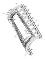
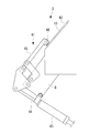
- FIG. 1 It is a schematic perspective view which shows the holding jig which concerns on 1st Embodiment of this invention, a frame attachment robot, and an automatic hammer. It is a perspective view which shows the holding part of the holding jig which concerns on 1st Embodiment of this invention, and shows the state which the pressing part of the holding part has separated from the skin of the fuselage
- the holding jig 1 according to the first embodiment of the present invention is, for example, when the skins constituting the aircraft panel are overlapped and joined by rivets, or when the frame is joined to the skin or stringer by rivets. , Used to hold the shape of the aircraft panel in a predetermined shape.
- the fuselage panel 10 of the aircraft has a plate-like skin 11 having a curved surface and an elongated skin provided on the skin 11 along one axial direction of the fuselage, ie, the longitudinal direction of the aircraft.
- the stringer 12 and a frame (not shown) provided along the circumferential direction of the trunk are combined.
- the fuselage panel 10 is made of, for example, aluminum or aluminum alloy, and an example of the size is 10 m in longitudinal length, 6 m in chord length, and 2 mm to 5 mm in thickness.
- the fuselage panel 10 has a substantially cylindrical fuselage portion of the aircraft divided in the axial direction and the circumferential direction. Therefore, the fuselage panel 10 has an arc shape in cross section in the direction perpendicular to the machine axis direction. In the body panel 10, two opposing sides parallel or oblique to the machine axis direction are located at the lower end of the body panel 10 when the body panel 10 is held by the holding jig 1.
- the two opposing sides that fit in a plane perpendicular to the machine axis direction are arc-shaped, and are located at the side ends of the fuselage panel 10 when the fuselage panel 10 is held by the holding jig 1 .
- the holding jig 1 has a transportable configuration, and is placed on a transport device (not shown) such as, for example, a chain conveyor, a belt conveyor, etc., and transported from one end side to the other end side.
- the transport device is such that a chain or a belt is driven by a motor, and the chain or the belt is wound parallel to the horizontal member 6 of the holding jig 1.
- the holding jig 1 is made of, for example, aluminum or an aluminum alloy. In FIG. 1, the holding jig 1 is shown being fixed to the fixing base 60.
- the plurality of grips 3 are supported by the support 5, fixed in relative position and integrated, and have a shape in which the bottoms of the two horizontal members 6 are accommodated in the same plane.
- the holding jig 1 can be transported by the transport device.
- the rivet setting operation is not performed on the body panel 10, and the rivet setting operation is performed on the trunk panel 10 in a state where the holding jig 1 is fixed at one place. Is done.
- the holding jig 1 is conveyed to another place by the conveying device.
- other automatic tapping machines are placed, and riveting by the other automatic tapping machines is performed.
- a working place by a worker is used, and riveting or inspection by hand is performed.
- the holding jig 1 which concerns on this embodiment is provided with the frame material 4, the support body 5, the holding part 3 grade
- the body panel 10 is held by the holding jig 1, the body panel 10 is held so as to be convex upward.
- the frame member 4 is composed of two straight horizontal members 6 extending in one direction, and two arch members 7 disposed between the two horizontal members 6 and formed in an arch shape.
- the horizontal members 6 and the arch members 7 of the frame member 4 support a support 5 described later.
- the horizontal members 6 are disposed, for example, parallel to the axial direction of the fuselage panel 10 along the axial direction of the fuselage panel 10 installed in the holding jig 1.
- the lower end of the arch member 7 is coupled to one end and the other end of the horizontal member 6.
- the holding jig 1 has a substantially wedge shape by the two horizontal members 6 and the two arch members 7.
- the girder member which couples one end or the other end of the two horizontal members 6 and extends in the vertical direction with respect to the horizontal member 6 is not provided.
- the length of the horizontal members 6 is longer than the axial length of the fuselage panel 10 manufactured by riveting, and the arrangement distance between the two horizontal members 6 is greater than the chordal length of the fuselage panel 10 manufactured by riveting Too long.
- the arch member 7 is a frame member 4 having a curved shape, and is disposed in a plane perpendicular to the axial direction of the fuselage panel 10 installed in the holding jig 1.
- the arch members 7 are provided one each on one end side and the other end side of the horizontal member 6 and are coupled to the two horizontal members 6.
- the frame member 4 has a configuration in which the horizontal member 6 and the arch member 7 are integrated.
- the curved shape, for example, the curvature, of the arch member 7 is provided substantially corresponding to the curvature of the body panel 10 to be manufactured.
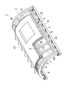
- the support 5 is disposed between two straight lower end support members 8 extending in the machine axis direction and the two lower end support members 8, and two arched side end support members 9 and the like. It consists of
- the lower end support 8 supports the lower end of the fuselage panel 10 via the grip 3.
- the lower end support member 8 is located above the horizontal member 6 of the frame member 4 and is parallel to, for example, the axial direction of the fuselage panel 10 along the axial direction of the fuselage panel 10 installed in the holding jig 1. Or it is arranged to be in an oblique direction.
- the lower end support members 8 are arranged corresponding to the two opposing sides of the body panel 10 installed in the holding jig 1. For example, the lower end support 8 is disposed along the ends of the straight two opposing sides of the fuselage panel 10.
- the body panel 10 to be manufactured is a single curved surface all having the same curvature along the machine axis direction
- the body panel 10 is a holding jig 1 so that the machine axis of the body panel 10 is parallel to the horizontal plane.
- the lower end support 8 and the horizontal member 6 extend in parallel directions.
- the body panel 10 to be manufactured is a double curved surface whose curvature changes along the machine axis direction
- the body panel 10 is installed on the holding jig 1 so that the machine axis of the body panel 10 is parallel to the horizontal plane.
- the extending direction of the lower end support member 8 is oblique to the extending direction of the horizontal member 6.
- the machine axis of the body panel 10 is inclined to the horizontal plane, and the top of the body panel 10 on the holding jig 1 is parallel to the horizontal plane along the machine axis direction
- the body panel 10 may be installed on the holding jig 1 so as to be substantially parallel. That is, the fuselage panel 10 is installed on the holding jig 1 such that the center on the smaller radius side of the cross section of the fuselage panel 10 is higher than the center on the larger radius side. As a result, the distances from the portal automatic drill 32 (see FIG. 5) to the fuselage panel 10 become substantially equal in the machine axis direction of the fuselage panel 10.
- the lower end support member 8 is supported by the horizontal member 6 via, for example, an auxiliary member 21 provided between the lower end support member 8 and the horizontal member 6.
- the auxiliary member 21 is a member having one end connected to the horizontal member 6 and the other end connected to the lower end support 8.
- a plurality of auxiliary members 21 are arranged along the longitudinal direction of the horizontal member 6 and the lower end support 8. .
- a plurality of grips 3 are arranged on the lower end support 8 at intervals.
- the length of the lower end support 8 is longer than the length in the machine axial direction of the body panel 10 to be manufactured, and the arrangement distance between the two lower end supports 8 is longer than the chord length of the body panel 10 to be manufactured.
- the lower end support member 8 is positioned lower than the held body panel 10 so that the grip portion 3 supports the lower end portion of the body panel 10 from the lower side.
- the lower end of the side end support 9 is coupled to one end and the other end of the lower end support 8 in the longitudinal direction.
- the side end support 9 supports the side end of the fuselage panel 10 via the grip 3.
- the side end support 9 is a member having a curved shape, and is disposed in a plane perpendicular to the axial direction of the fuselage panel 10 installed in the holding jig 1.
- the side end support members 9 are disposed corresponding to the two opposing sides of the body panel 10 installed in the holding jig 1.
- the side end supports 9 are provided respectively on one end side and the other end side of the lower end support 8 in the longitudinal direction, and are connected to the two lower end supports 8.
- the support 5 has a configuration in which the lower end support 8 and the side end support 9 are integrated.
- the curved shape, for example, the curvature, of the side end support 9 is provided corresponding to the curvature of the body panel 10 to be manufactured.
- a plurality of gripping portions 3 having the same configuration as the gripping portions 3 described above may be provided on the side end support members 9, and the gripping portions 3 may grip and support the side edge of the body panel 10.
- the plurality of gripping portions 3 provided on the side end support members 9 are provided at intervals corresponding to the curvature of the body panel 10 to be manufactured. Therefore, when the plurality of grips 3 grip the body panel 10, the body panel 10 gripped by the grips 3 is held so as to have the curvature of the body panel 10 to be manufactured.
- the body panel 10 to be manufactured is a single curved surface having the same curvature all along the machine direction, the curvature connecting the grips 3 in the side end support 9 on one end side and the side end support on the other side
- the curvature connecting the grips 3 in the material 9 is the same.
- the body panel 10 to be manufactured is a double curved surface whose curvature changes along a uniaxial direction, the curvature connecting the grips 3 in the side end support 9 at one end is the side end support 9 at the other end. It becomes larger than the curvature which ties the holding part 3 in.
- the lower end support 8 and the side end support 9 are fixed to the frame 4, and the body panel 10 held by the holding jig 1 is of a predetermined size.
- the present invention is not limited to this example, and at least one of the lower end support 8 and the side end support 9 may be movable.
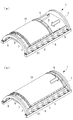
- the position at which the side end support 9 is fixed may be changeable along the axial direction of the body panel 10 according to the shape of the body panel 10 to be held.
- the side end support 9 is positioned on the middle side of the holding jig 1 in the machine axis direction, or as shown in FIG. 3 (b), the side end support 9 is held. It is positioned on the end side of the jig 1 in the machine axis direction.
- the position where the lower end support member 8 is fixed may be changeable in the circumferential direction of the body panel 10 according to the shape of the body panel 10 to be held. Thereby, even when the chord length of the body panel 10 is different, the positions of the plurality of gripping portions 3 are changed, so that the plurality of gripping portions 3 can grip the body panel 10, and one type of holding jig 1 is a plurality of types Can hold an aircraft panel.
- the gripping portion 3 has a configuration for gripping an end portion of the body panel 10 having the skin 11, and a plurality of gripping portions 3 are provided at predetermined intervals.
- the gripping portion 3 is supported by the lower end support 8 or the side end support 9.
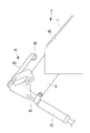
- the gripping portion 3 has, for example, a toggle clamp 41 and a receiving portion 42 as shown in FIGS. 7 and 8.
- the toggle clamp 41 is a clamp using a toggle mechanism, and has a cylinder 43 fixed to the lower end support 8 or the side end support 9 and a rod-like pressing portion 45 moved by a cylinder rod 44 provided in the cylinder 43. It consists of etc.
- the cylinder 43 is an example of a drive unit.
- a roller 46 is provided at the tip of the pressing portion 45.
- the roller 46 is rotatable with a direction perpendicular to the moving direction of the pressing unit 45 as a rotation axis.
- the pressing portion 45 presses the end of the skin 11 from one surface side (outer surface side) of the skin 11 of the body panel 10.
- a receiving portion 42 for receiving a pressing force by the pressing portion 45 is provided on the other surface side (inner surface side) of the skin 11.
- the receiving portion 42 is fixed to, for example, the lower end support 8.
- the pressing portion 45 is separated from the skin 11.
- the pressing unit 45 retracts to a position not interfering with the body panel 10 in order to place the body panel 10 on the holding jig 1 or to remove the body panel 10 from the holding jig 1.
- the cylinder 43 is connected to a compressor, and a piston connected to the cylinder rod 44 is driven by, for example, air pressure.
- the installation number of the gripping portions 3 and the gripping force with respect to the skin 11 are determined by simulation or verification test so that the fuselage panel 10 does not shift or vibrate at the time of rivet setting operation.
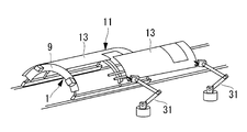
- the divided panel 13 is lifted by the divided panel mounting robot 31 or the like, and nothing is placed thereon.
- the divided panel 13 is placed at a predetermined position of the side end support 9 of the holding jig 1 with respect to the holding jig 1 of FIG.
- the division panel 13 is a member before the fuselage panel 10 is fastened by rivets, and is a member obtained by dividing the fuselage panel 10 into a plurality of pieces.
- the divided panel 13 is, for example, a member which is long in a direction parallel to the machine axis direction and divided into a plurality of parts in the circumferential direction of the trunk panel 10.
- the divided panel 13 is obtained by dividing the body panel 10 into four in the circumferential direction, for example.
- the skins 11 of the adjacent divided panels 13 on the holding jig 1 are overlapped. That is, the end of the skin 11 of the other divided panel 13 is placed on the end of the skin 11 of one divided panel 13. Then, the overlapping portions of the skins 11 are temporarily fixed by rivets.
- the temporarily fixed body panel 10 is fixed by the grip portion 3 provided on the lower end support member 8.
- the body panel 10 may be held from below using an initial shape holding jig (not shown) other than the holding jig 1 .
- the body panel 10 temporarily fixed and fixed by the holding unit 3 is moved to the next process in a state of being installed in the holding jig 1.
- the movement of the holding jig 1 is performed, for example, by a conveyor located at the bottom of the holding jig 1.
- the initial shape holding jig is removed from the body panel 10 when moving the holding jig 1.
- the holding jig 1 holds the body panel 10 so that the shape of the completed body panel 10 is maintained even in this state.
- the fuselage panel 10 on the moved holding jig 1 is, for example, fastened with a rivet by an automatic hammer or a manual operation of a worker.
- an overlapping portion of adjacent skins 11 is an automatic hammering machine (e.g. Work of fastening with a gate-type automatic hammer 32) or the skin 11 of the body panel 10 supported by the holding jig 1 on the inner surface side of the body panel 10, that is, as shown in FIG.
- the hinge attachment of the aircraft door attached to the fuselage panel 10 and the attachment of the wiring piping bracket or the sensor mounting bracket are performed by a manual rivet setting operation.
- the fuselage panel 10 in which the rivet fastening is completed is moved to the next process in a state of being installed in the holding jig 1. After the riveting is completed, the inspection or a correction based on the inspection result is performed.
- the fuselage panel 10 for which the inspection and repair have been completed is lifted and removed from the holding jig 1 according to the present embodiment by a crane or the like. Thereafter, the body panel 10 is placed on another jig, and painting is performed.
- the holding jig 1 supports the body panel 10 at the end of the body panel 10. That is, in the body panel 10 having the skin 11, the ends of two opposing sides (for example, two opposing sides parallel to the machine axis direction) of the body panel 10 are gripped by the plurality of gripping portions 3. At this time, the plurality of grips 3 are integrally supported via the support 5 provided corresponding to the body panel 10.
- the fuselage panel 10 is held so that the cross section cut in the direction perpendicular to the machine axis direction has a curved shape and the upper side is convex. Since the fuselage panel 10 is held from the lower side of the fuselage panel 10 at the ends of the two sides of the fuselage panel 10, for example, the holding jig 1 can hold the fuselage panel 10 with a simple structure. Further, the holding jig 1 can be transported in a state of holding the body panel 10, for example, the frame 4 and the support 5 are integrated, and the bottom of the horizontal member 6 can be contained in the same plane. Since the holding jig 1 holds the body panel 10, it can be conveyed.
- the holding jig 1 of the present embodiment has a structure for supporting the fuselage panel 10 at the end of the fuselage panel 10, so that a plurality of frames installed on the fuselage panel 10 like a conventional jig. It is simplified and reduced in weight as compared to a jig provided with a plurality of positioning members correspondingly. Therefore, in a state in which the body panel 10 is held with respect to the holding jig 1, the body panel 10 is movable together with the holding jig 1. As a result, while moving the work place where the holding jig 1 is different, the riveting operation is performed by the automatic hammer on the fuselage panel 10, the riveting operation is performed manually, or the inspection and rework is performed. Work can be done.
- the body panel 10 is surrounded by two opposing sides parallel or oblique to the straight machine axis direction and two opposing sides that fit in a plane perpendicular to the arc-shaped machine axis direction.
- the shape of the body panel 10 held by the holding jig according to the present invention is not limited to this example.
- the cutout portion 16 may be formed in the body panel 10 according to the combination of the plurality of body panels 10 or the like.
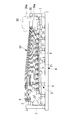
- the holding jig 2 according to the present embodiment can hold the body panel 10 with respect to the body panel 10 in which the notches 16 are formed.
- the notched horizontal end support 22 and the notched side end support 23 separately from the lower end support 8 or the side end support 9 described above are installed in the holding jig 2.
- the notch horizontal end support 22 and the notch side end support 23 constitute a second support.
- the notched horizontal end support 22 is supported by, for example, the horizontal member 6 or the lower end support 8 via, for example, the support 24.
- the notched horizontal end support 22 supports the horizontal end of the notched portion 16 of the fuselage panel 10 via the grip portion 3.
- the notch horizontal end support member 22 is positioned above the horizontal member 6 and the lower end support member 8 of the frame member 4 and extends along the axial direction of the fuselage panel 10 installed on the holding jig 2, for example, the fuselage panel 10 It is arranged to be parallel or oblique to the machine axis direction of
- a plurality of grips 3 are arranged spaced apart from one another.
- the notched horizontal end support 22 is located below the held fuselage panel 10 so that the grip 3 supports the horizontal end of the notch 16 of the fuselage panel 10 from below.
- One longitudinal end of the cutout horizontal end support 22 is coupled to the arch member 7, and the other longitudinal end of the cutout horizontal end support 22 is coupled to, for example, the auxiliary member 24.
- the notched end support 23 supports the side end of the fuselage panel 10 from below.
- the notch side end support 23 is a member having a curved shape, and is disposed in a plane perpendicular to the machine axis direction of the body panel 10 installed in the holding jig 2.
- the notch side end support 23 is disposed corresponding to the end of the side having the curvature of the notch 16 of the body panel 10 installed in the holding jig 2.
- the curved shape, for example, the curvature, of the notch side end support 23 is provided corresponding to the curvature of the body panel 10 to be manufactured. Similar to the side end support 9, the notch side end support 23 is provided with a plurality of gripping portions 3 at intervals along the longitudinal direction of the cut side end support 23. The plurality of grips 3 grips the end of the notch 16 of the fuselage panel 10, whereby the fuselage panel 10 gripped by the grips 3 is held so as to have the curvature of the fuselage panel 10 to be manufactured.
- the holding jig 2 supports the body panel 10 at the end of the notch portion 16 of the body panel 10. That is, in the body panel 10 having the skin 11, the ends of the notches 16 of the body panel 10 are gripped by the plurality of gripping portions 3. At this time, the plurality of grips 3 are integrally supported via the notched horizontal end support 22 and the notched end support 23 provided corresponding to the notches 16 of the body panel 10. Thus, it is possible to suppress deformation such as bending that occurs in the skin 11 in the periphery of the notch portion 16.
- the side end of the body panel 10 is gripped by the grip portion 3 provided on the side end support 9 or the notch side end support 23
- the invention is not limited to this example.
- a plurality of rods are provided at intervals along the curved shape of the side end support 9 or the cut side end support 23.
- the rod protrudes in the radial direction (vertical direction with respect to the axial direction) of the fuselage panel 10, and has an adjustable projection length.
- the plurality of rods are adjusted in projecting length so as to be in the shape of the body panel 10 to be held.
- the fuselage panel 10 is held so as to have the curvature of the fuselage panel 10 to be manufactured by placing the fuselage panel 10 on the upper surfaces of the plurality of rods (protruding ends of the rods).
- the body panel 10 to be manufactured is a single curved surface having the same curvature all along the machine direction, the curvature connecting the upper surface of the rod in the side end support 9 at one end and the side end support at the other end
- the curvature connecting the upper surfaces of the rods in the material 9 is the same.
- the body panel 10 to be manufactured is a double curved surface whose curvature changes along a uniaxial direction, the curvature connecting the upper surfaces of the rods in the side end support 9 at one end is the side end support 9 at the other end. Is greater than the curvature connecting the top surfaces of the rods.
- the present invention is not limited to this example, and as shown in FIG.
- the radii of the arch members 7 may be made different.
- the body panel 10 to be manufactured is a double curved surface whose curvature changes along the machine axis direction
- the body panel 10 is installed on the holding jig 1 so that the machine axis of the body panel 10 is parallel to the horizontal plane.
- the cross section of the fuselage panel 10 is smaller, the smaller radius is located lower than the larger radius.
- the component 36 a that protrudes in the machine axial direction in the automatic tapping machine 36 is on the fuselage panel 10 side of the arch material 7. It interferes with the side.
- the automatic hammering machine 36 can be installed so as to be located above the arch material 7, and the interference between the arch material 7 and the automatic hammering machine 36 can be prevented.
Landscapes
- Engineering & Computer Science (AREA)
- Mechanical Engineering (AREA)
- Manufacturing & Machinery (AREA)
- Aviation & Aerospace Engineering (AREA)
- Transportation (AREA)
- Automatic Assembly (AREA)
- Automobile Manufacture Line, Endless Track Vehicle, Trailer (AREA)
- Jigs For Machine Tools (AREA)
- Manipulator (AREA)
- Clamps And Clips (AREA)
Priority Applications (5)
| Application Number | Priority Date | Filing Date | Title |
|---|---|---|---|
| CN201680080256.5A CN108602568A (zh) | 2016-02-02 | 2016-11-17 | 保持夹具 |
| CA3011666A CA3011666C (en) | 2016-02-02 | 2016-11-17 | Holding fixture |
| EP16889385.7A EP3392154B1 (en) | 2016-02-02 | 2016-11-17 | Holding jig |
| US16/070,434 US10843820B2 (en) | 2016-02-02 | 2016-11-17 | Holding fixture |
| BR112018015490A BR112018015490A2 (pt) | 2016-02-02 | 2016-11-17 | gabarito de retenção |
Applications Claiming Priority (2)
| Application Number | Priority Date | Filing Date | Title |
|---|---|---|---|
| JP2016-018427 | 2016-02-02 | ||
| JP2016018427A JP6580495B2 (ja) | 2016-02-02 | 2016-02-02 | 保持治具 |
Publications (1)
| Publication Number | Publication Date |
|---|---|
| WO2017134902A1 true WO2017134902A1 (ja) | 2017-08-10 |
Family
ID=59499490
Family Applications (1)
| Application Number | Title | Priority Date | Filing Date |
|---|---|---|---|
| PCT/JP2016/084131 WO2017134902A1 (ja) | 2016-02-02 | 2016-11-17 | 保持治具 |
Country Status (7)
Cited By (3)
| Publication number | Priority date | Publication date | Assignee | Title |
|---|---|---|---|---|
| CN110216235A (zh) * | 2019-06-03 | 2019-09-10 | 西安飞机工业(集团)有限责任公司 | 一种基于实测数据的柔性机身壁板装配工装及装配方法 |
| CN111731505A (zh) * | 2020-06-12 | 2020-10-02 | 陕西飞机工业(集团)有限公司 | 一种飞机普通框缘装配方法 |
| CN114310122A (zh) * | 2022-02-08 | 2022-04-12 | 江南造船(集团)有限责任公司 | 一种t型材弧形面板的保形工装及夹持单元 |
Families Citing this family (8)
| Publication number | Priority date | Publication date | Assignee | Title |
|---|---|---|---|---|
| LT3319969T (lt) | 2015-07-06 | 2024-06-10 | Turning Point Therapeutics, Inc. | Diarilo makrociklo polimorfas |
| CN206523497U (zh) * | 2017-03-14 | 2017-09-26 | 京东方科技集团股份有限公司 | 治具 |
| CN111168443B (zh) * | 2020-03-16 | 2025-04-25 | 沈阳飞机工业(集团)有限公司 | 拼装式蒙皮铣切夹具及其制造方法 |
| CN112212775B (zh) * | 2020-09-28 | 2022-03-22 | 中国航发贵州黎阳航空动力有限公司 | 一种弧面薄壁零件检测和防变形装置及使用方法 |
| CN112173163B (zh) * | 2020-10-24 | 2025-04-25 | 西安航空学院 | 一种无人机3d增材基体复材蒙皮制造工艺 |
| KR102451064B1 (ko) * | 2021-06-28 | 2022-10-07 | 디와이피엔에프 주식회사 | 사일로용 셀패널 지그 및 이를 가지는 사일러용 셀패널 제조 장치 |
| US11866201B2 (en) * | 2022-05-03 | 2024-01-09 | The Boeing Company | Method and apparatus for the application of frame to fuselage pull-up force via fuselage skin waterline tensioning |
| CN120347557A (zh) * | 2025-06-20 | 2025-07-22 | 中航西安飞机工业集团股份有限公司 | 一种多维感知镜像铣削力数字化快速夹持装置 |
Citations (4)
| Publication number | Priority date | Publication date | Assignee | Title |
|---|---|---|---|---|
| JPH04336997A (ja) * | 1991-05-14 | 1992-11-25 | Bridgestone Cycle Co | 大型パネルの穿孔装置とその穿孔方法 |
| JP2013198918A (ja) * | 2012-03-23 | 2013-10-03 | Mitsubishi Heavy Ind Ltd | 自動打鋲装置 |
| DE102013004598A1 (de) * | 2013-03-15 | 2014-09-18 | Dürr Systems GmbH | itsplattform |
| JP2015030348A (ja) * | 2013-08-01 | 2015-02-16 | 三菱重工業株式会社 | 支持治具およびそれを用いた航空機の組立方法 |
Family Cites Families (25)
| Publication number | Priority date | Publication date | Assignee | Title |
|---|---|---|---|---|
| SE451185B (sv) | 1985-03-11 | 1987-09-14 | Atlas Copco Ab | Nitningsanordning for sammanfogning av tva eller flera platsektioner |
| US4691905A (en) * | 1985-04-18 | 1987-09-08 | Nissan Motor Co., Ltd. | Machine for holding workpiece |
| US5033178A (en) * | 1988-07-06 | 1991-07-23 | The Boeing Company | Assembly jig and method for making wing panels |
| US4995146A (en) * | 1988-10-26 | 1991-02-26 | The Boeing Company | Assembly jig and method for making wing spars |
| US5565242A (en) * | 1992-09-21 | 1996-10-15 | The Boeing Company | Lubricant applications to a hole |
| US5560102A (en) * | 1992-10-13 | 1996-10-01 | The Boeing Company | Panel and fuselage assembly |
| US5350162A (en) * | 1993-03-08 | 1994-09-27 | Cushing Meredith K | Apparatus for assembling reinforcing bar pier cages |
| US5617622A (en) * | 1995-06-06 | 1997-04-08 | Anderson; Tommy G. | Rotatable work platform with clamps for wall and truss fabrication |
| ES2146140B1 (es) * | 1996-10-15 | 2001-04-01 | Torres Martinez M | Maquina para el soporte y mecanizado de piezas. |
| DE29722276U1 (de) * | 1997-12-17 | 1999-05-06 | KUKA Schweissanlagen GmbH, 86165 Augsburg | Spanneinrichtung für Werkstücke |
| GB9925610D0 (en) * | 1999-10-29 | 1999-12-29 | British Aerospace | Workpiece support |
| SE523035C2 (sv) * | 2000-04-13 | 2004-03-23 | Saab Ab | Verktyg för fixering av skrovdetaljer |
| CA2324820C (en) * | 2000-10-30 | 2004-05-04 | Clayton Dean Babchuk | Workpiece support apparatus |
| ES2219472T3 (es) * | 2001-01-16 | 2004-12-01 | Airbus Deutschland Gmbh | Dispositivo de retencion para la retencion de piezas de construccion de gran formato. |
| US20030034602A1 (en) * | 2001-08-18 | 2003-02-20 | Kavanaugh Chris J. | Universal holding fixture |
| JP2003329010A (ja) * | 2002-05-16 | 2003-11-19 | Koganei Corp | クランプ装置 |
| US7076856B2 (en) * | 2002-11-14 | 2006-07-18 | The Boeing Company | Adjustable system and method for supporting and joining structural members |
| CA2449918A1 (en) * | 2002-11-19 | 2004-05-19 | Vinode Ramnauth | Apparatus and method for moving frameworks between workstations |
| US20040187291A1 (en) * | 2003-03-31 | 2004-09-30 | Richard Syrek | Method for changing fixtures used to position a plurality of different workpieces on an assembly line |
| US7765662B2 (en) * | 2006-09-14 | 2010-08-03 | Mckown Jeffrey A | Holding fixture for machining bearing caps |
| JP5035533B2 (ja) | 2007-09-24 | 2012-09-26 | 豊和工業株式会社 | クランプ装置 |
| US9156510B2 (en) * | 2012-10-17 | 2015-10-13 | Btm Company Llc | Clamp mounting system |
| KR101459465B1 (ko) * | 2013-06-14 | 2014-11-07 | 현대자동차 주식회사 | 트렁크 리드 및 테일 게이트 공용 로딩 지그장치 |
| CN103600249A (zh) * | 2013-11-15 | 2014-02-26 | 长春轨道客车股份有限公司 | 轨道车辆大部件加工自动化工装 |
| CN104400086B (zh) * | 2014-10-10 | 2016-07-06 | 南京航空航天大学 | 飞机蒙皮镜像铣削方法及装备 |
-
2016
- 2016-02-02 JP JP2016018427A patent/JP6580495B2/ja active Active
- 2016-11-17 CN CN201680080256.5A patent/CN108602568A/zh active Pending
- 2016-11-17 BR BR112018015490A patent/BR112018015490A2/pt not_active IP Right Cessation
- 2016-11-17 WO PCT/JP2016/084131 patent/WO2017134902A1/ja active Application Filing
- 2016-11-17 US US16/070,434 patent/US10843820B2/en active Active
- 2016-11-17 CA CA3011666A patent/CA3011666C/en not_active Expired - Fee Related
- 2016-11-17 EP EP16889385.7A patent/EP3392154B1/en active Active
Patent Citations (4)
| Publication number | Priority date | Publication date | Assignee | Title |
|---|---|---|---|---|
| JPH04336997A (ja) * | 1991-05-14 | 1992-11-25 | Bridgestone Cycle Co | 大型パネルの穿孔装置とその穿孔方法 |
| JP2013198918A (ja) * | 2012-03-23 | 2013-10-03 | Mitsubishi Heavy Ind Ltd | 自動打鋲装置 |
| DE102013004598A1 (de) * | 2013-03-15 | 2014-09-18 | Dürr Systems GmbH | itsplattform |
| JP2015030348A (ja) * | 2013-08-01 | 2015-02-16 | 三菱重工業株式会社 | 支持治具およびそれを用いた航空機の組立方法 |
Cited By (4)
| Publication number | Priority date | Publication date | Assignee | Title |
|---|---|---|---|---|
| CN110216235A (zh) * | 2019-06-03 | 2019-09-10 | 西安飞机工业(集团)有限责任公司 | 一种基于实测数据的柔性机身壁板装配工装及装配方法 |
| CN110216235B (zh) * | 2019-06-03 | 2024-02-09 | 西安飞机工业(集团)有限责任公司 | 一种基于实测数据的柔性机身壁板装配工装及装配方法 |
| CN111731505A (zh) * | 2020-06-12 | 2020-10-02 | 陕西飞机工业(集团)有限公司 | 一种飞机普通框缘装配方法 |
| CN114310122A (zh) * | 2022-02-08 | 2022-04-12 | 江南造船(集团)有限责任公司 | 一种t型材弧形面板的保形工装及夹持单元 |
Also Published As
| Publication number | Publication date |
|---|---|
| EP3392154A4 (en) | 2018-12-05 |
| CA3011666A1 (en) | 2017-08-10 |
| JP2017136930A (ja) | 2017-08-10 |
| EP3392154B1 (en) | 2021-01-06 |
| CA3011666C (en) | 2021-02-09 |
| BR112018015490A2 (pt) | 2018-12-18 |
| EP3392154A1 (en) | 2018-10-24 |
| CN108602568A (zh) | 2018-09-28 |
| US10843820B2 (en) | 2020-11-24 |
| JP6580495B2 (ja) | 2019-09-25 |
| US20190023417A1 (en) | 2019-01-24 |
Similar Documents
| Publication | Publication Date | Title |
|---|---|---|
| WO2017134902A1 (ja) | 保持治具 | |
| WO2017134899A1 (ja) | 航空機パネル製造方法及び航空機パネル製造システム | |
| JP6513585B2 (ja) | 形状保持治具及び航空機パネル製造方法 | |
| JP6513584B2 (ja) | 保持治具固定装置 | |
| EP1797973A1 (en) | Combined panel bender-press brake machine | |
| RU2433028C2 (ru) | Способ изготовления машин | |
| JP7176438B2 (ja) | ドア取付方法、およびそれに用いられるドア移動装置ならびに治具 | |
| JPWO2018088140A1 (ja) | 部品製造方法及び部品製造システム | |
| KR100525361B1 (ko) | 중량물 조립위치 결정장치 | |
| WO2018110102A1 (ja) | 搬送用治具 | |
| KR101723958B1 (ko) | 다자유도 중력보상 작업보조로봇 | |
| CN119858047A (zh) | 壁板定位工装装置 | |
| JP6509003B2 (ja) | パネル部材の溶接方法 | |
| JP6486340B2 (ja) | 加圧接合装置及び加圧接合方法 | |
| JP4918775B2 (ja) | ワーク搬送装置 | |
| JPH10230392A (ja) | ワーク姿勢変換装置 | |
| KR20160080199A (ko) | 분해와 조립이 용이한 로봇 행거 |
Legal Events
| Date | Code | Title | Description |
|---|---|---|---|
| 121 | Ep: the epo has been informed by wipo that ep was designated in this application |
Ref document number: 16889385 Country of ref document: EP Kind code of ref document: A1 |
|
| WWE | Wipo information: entry into national phase |
Ref document number: 3011666 Country of ref document: CA |
|
| WWE | Wipo information: entry into national phase |
Ref document number: 2016889385 Country of ref document: EP |
|
| ENP | Entry into the national phase |
Ref document number: 2016889385 Country of ref document: EP Effective date: 20180718 |
|
| NENP | Non-entry into the national phase |
Ref country code: DE |
|
| REG | Reference to national code |
Ref country code: BR Ref legal event code: B01A Ref document number: 112018015490 Country of ref document: BR |
|
| ENP | Entry into the national phase |
Ref document number: 112018015490 Country of ref document: BR Kind code of ref document: A2 Effective date: 20180730 |