WO2017134899A1 - 航空機パネル製造方法及び航空機パネル製造システム - Google Patents
航空機パネル製造方法及び航空機パネル製造システム Download PDFInfo
- Publication number
- WO2017134899A1 WO2017134899A1 PCT/JP2016/084073 JP2016084073W WO2017134899A1 WO 2017134899 A1 WO2017134899 A1 WO 2017134899A1 JP 2016084073 W JP2016084073 W JP 2016084073W WO 2017134899 A1 WO2017134899 A1 WO 2017134899A1
- Authority
- WO
- WIPO (PCT)
- Prior art keywords
- holding jig
- aircraft panel
- panel
- holding
- aircraft
- Prior art date
Links
Images
Classifications
-
- B—PERFORMING OPERATIONS; TRANSPORTING
- B21—MECHANICAL METAL-WORKING WITHOUT ESSENTIALLY REMOVING MATERIAL; PUNCHING METAL
- B21J—FORGING; HAMMERING; PRESSING METAL; RIVETING; FORGE FURNACES
- B21J15/00—Riveting
- B21J15/10—Riveting machines
- B21J15/14—Riveting machines specially adapted for riveting specific articles, e.g. brake lining machines
- B21J15/142—Aerospace structures
-
- B—PERFORMING OPERATIONS; TRANSPORTING
- B21—MECHANICAL METAL-WORKING WITHOUT ESSENTIALLY REMOVING MATERIAL; PUNCHING METAL
- B21J—FORGING; HAMMERING; PRESSING METAL; RIVETING; FORGE FURNACES
- B21J15/00—Riveting
- B21J15/38—Accessories for use in connection with riveting, e.g. pliers for upsetting; Hand tools for riveting
- B21J15/42—Special clamping devices for workpieces to be riveted together, e.g. operating through the rivet holes
-
- B—PERFORMING OPERATIONS; TRANSPORTING
- B64—AIRCRAFT; AVIATION; COSMONAUTICS
- B64C—AEROPLANES; HELICOPTERS
- B64C1/00—Fuselages; Constructional features common to fuselages, wings, stabilising surfaces or the like
- B64C1/06—Frames; Stringers; Longerons ; Fuselage sections
- B64C1/12—Construction or attachment of skin panels
-
- B—PERFORMING OPERATIONS; TRANSPORTING
- B64—AIRCRAFT; AVIATION; COSMONAUTICS
- B64F—GROUND OR AIRCRAFT-CARRIER-DECK INSTALLATIONS SPECIALLY ADAPTED FOR USE IN CONNECTION WITH AIRCRAFT; DESIGNING, MANUFACTURING, ASSEMBLING, CLEANING, MAINTAINING OR REPAIRING AIRCRAFT, NOT OTHERWISE PROVIDED FOR; HANDLING, TRANSPORTING, TESTING OR INSPECTING AIRCRAFT COMPONENTS, NOT OTHERWISE PROVIDED FOR
- B64F5/00—Designing, manufacturing, assembling, cleaning, maintaining or repairing aircraft, not otherwise provided for; Handling, transporting, testing or inspecting aircraft components, not otherwise provided for
- B64F5/10—Manufacturing or assembling aircraft, e.g. jigs therefor
-
- B—PERFORMING OPERATIONS; TRANSPORTING
- B23—MACHINE TOOLS; METAL-WORKING NOT OTHERWISE PROVIDED FOR
- B23P—METAL-WORKING NOT OTHERWISE PROVIDED FOR; COMBINED OPERATIONS; UNIVERSAL MACHINE TOOLS
- B23P2700/00—Indexing scheme relating to the articles being treated, e.g. manufactured, repaired, assembled, connected or other operations covered in the subgroups
- B23P2700/01—Aircraft parts
Definitions
- the present invention relates to an aircraft panel manufacturing method and an aircraft panel manufacturing system.
- the fuselage panel of the aircraft is configured by combining a plate-like skin having a curved surface, an elongated stringer provided on the skin along the longitudinal direction of the fuselage, and a frame provided along the circumferential direction of the fuselage, etc. Ru.
- Bonding of overlapping portions of adjacent skins and bonding of a frame to a skin or a stringer are performed after the position of each part is accurately determined using a positioning jig.
- a rivet is used for the connection between parts.
- a positioning jig is used by being fixed at a predetermined position in a factory, and the above-mentioned coupling of the skins and the coupling of the frame are performed at the predetermined position to manufacture the body panel.
- the fuselage panel being manufactured was moved from the work place of one process to the work place of the next process, it was removed from the positioning jig and moved, and the positioning jig itself did not move.
- the positioning jig fixed and used at the predetermined position is manufactured in advance according to the shape of the body panel to be manufactured.
- the fuselage panel is not only in the case of a single curved surface having a straight line in the longitudinal direction, but also in the case of a double curved surface having a curvature in the longitudinal direction. Therefore, many types of positioning jigs need to be manufactured in accordance with the shape of the body panel, and the cost for manufacturing and managing the jigs is also increased.
- the present invention has been made in view of such circumstances, and it is an aircraft panel manufacturing method capable of simplifying the manufacture and management of a jig and suppressing the cost involved in the manufacture and management of a jig. And an aircraft panel manufacturing system.
- the holding jig has an aircraft panel having a plurality of plate members having a curved cross section, and the cross section of the aircraft panel has a convex curved shape. And holding the plate members of the aircraft panel held by the holding jig, and combining the overlapping portions with a rivet; and the plate members being connected. Moving the holding jig on which the aircraft panel is held; and along the curved shape of the aircraft panel with respect to the plurality of plate members of the aircraft panel held on the moved holding jig. Connecting the curvilinear members by rivets.
- the plurality of plate members constituting the aircraft panel are fastened by the rivets in the overlapping portion and then moved to different locations, and the curvilinear member is attached to the plate members of the aircraft panel by the rivets .
- a step of connecting overlapping portions of the plurality of plate members by rivets a step of moving the holding jig on which the aircraft panel is held, and a step of connecting curvilinear members by rivets. , The aircraft panel is maintained in the holding jig.
- the holding jig is moved while maintaining the aircraft panel held by the holding jig through the respective steps, so that the removing work from the positioning jig and the attaching work to the positioning jig are omitted. Is possible.
- the holding jig in the step in which the holding jig holds the aircraft panel, the holding jig has a plurality of gripping portions, and the plurality of gripping portions only have peripheral portions of the plurality of plate members. It may be gripped to hold the aircraft panel.
- the holding jig has a plurality of gripping portions for gripping end portions of two opposing sides of the aircraft panel, and the plurality of gripping portions are peripheral portions of the plurality of plate-like members. It may be gripped to hold the aircraft panel.
- the two opposing sides are two sides extending in a direction perpendicular to a cross section having a convex curved shape on the aircraft panel, and the aircraft is held in the holding jig. It is the lower edge of the panel.
- the aircraft panel having the upwardly convex curved shape is held and supported by the lower peripheral portion, the aircraft panel with small rigidity can be stably held.
- the structural member for supporting the central portion of the plate-like member in the structure of the holding jig while appropriately maintaining the shape of the peripheral portion that requires accuracy in assembly.
- the rivets are connected by an automatic riveting machine.
- the holding jig is fixed to the buffer space after at least one of the step of connecting the overlapping portions of the plurality of plate members by rivets and the step of connecting the curvilinear members by rivets. And the automatic tapping machine performs the connection of the rivets in the buffer space.
- the buffer space is provided after the rivet setting operation by the automatic riveting machine, and the holding jig is fixed there, and in some cases, since the automatic riveting machine performs riveting, the aircraft panel Can absorb the time difference of working time caused by the type of
- the holding jig is moved in one direction along the transport track, and connecting the overlapping portions of the plurality of plate members by rivets, and connecting the curvilinear members by rivets. In the step, the holding jig is fixed at each processing space.
- the transfer track is provided, the holding jig moves in one direction along the transfer track, and in each work space, the holding jig is fixed and the riveting operation is performed on the aircraft panel Etc. That is, while work is being performed, the aircraft panel is fixed, and the aircraft panel moves only when being transported between work spaces.
- the holding jig is provided corresponding to a plurality of holding parts holding end portions of two opposing sides of the aircraft panel, and the aircraft panel held by the plurality of holding parts.
- the plurality of holding portions having one frame member and supported by the first frame member hold the aircraft panel at the ends of two opposing sides of the aircraft panel along the one axial direction,
- the aircraft panel is held so that a cross section cut in the direction perpendicular to the uniaxial direction has a curved shape convex upward, and the aircraft panel can be transported while being held.
- a frame is attached to a skin or a stringer while superimposing a plurality of adjacent skins in a single work space with a jig having a complicated structure.
- a jig that holds both ends of the plate-like member of the aircraft panel and holds the cross-section of the plate-like member in an upwardly convex curvilinear shape, it is possible to carry out other steps later Curved members (e.g. frames) can be attached to plate-like members (e.g. skins) or stringers provided on the skins.
- the aircraft panel can be assembled with a simple jig.
- An aircraft panel manufacturing method is an aircraft panel manufacturing method for manufacturing a plurality of types of aircraft panels on the same line, wherein a plurality of plate members constituting the aircraft panels are used as a holding jig.
- An aircraft panel manufacturing method is an aircraft panel manufacturing method for manufacturing a plurality of types of aircraft panels on the same line, wherein a plurality of plate members constituting the aircraft panels are used as a holding jig.
- Machining A step of conveying from A to a second processing area, in the second processing area, and a step of coupling the overlapping portion of said plurality of plate-shaped members to each other by rivets.
- An aircraft panel manufacturing method is an aircraft panel manufacturing method for manufacturing a plurality of types of aircraft panels on the same line, comprising a plurality of plates constituting the aircraft panels in a first processing area And temporarily holding them together so that the cross section of the aircraft panel has a convex curve shape upward, and the first holding jig on which the aircraft panel is placed.
- Transferring from a processing area to a second processing area, connecting the overlapping portions of the plurality of plate members by rivets in the second processing area, and holding the aircraft panel mounted thereon Transporting a jig from the second processing area to a third processing area; and attaching another member to the aircraft panel on the holding jig at the third processing area And a step.
- An aircraft panel manufacturing method is an aircraft panel manufacturing system for manufacturing a plurality of types of aircraft panels on the same line, wherein the space between the first processing area and the second processing area is the above A holding jig that moves while holding the aircraft panel, a shape holding jig installed in the first processing area and used in combination with the holding jig, and installed in the second processing area And a striking device for fastening a rivet to the aircraft panel on the holding jig, wherein the holding jig has a jig frame having a common portion common to the plurality of types of aircraft panels, and A support member provided inside a jig frame, and a grip portion provided on the support member for gripping the peripheral edge in the longitudinal direction of the aircraft panel, the cross section of the aircraft panel only by the grip portion Held in a convex curved shape on.
- the assembly can be performed with a simple jig, and manufacturing of the jig
- the management can be simplified and the cost for manufacturing and managing the jig can be reduced.
- the range which can apply an automatic riveting machine can be made to increase about the fastening operation of a rivet.
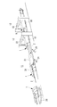
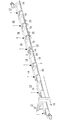
- FIG. 1 to 3 are perspective views showing a fuselage panel manufacturing system according to an embodiment of the present invention.
- arrow A indicates that the transport track 2 is continuous
- arrow B indicates that the transport method is changed.
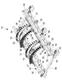
- the fuselage panel manufacturing system includes a holding jig 1 for holding the fuselage panel 10 and a transport track 2 for transporting the holding jig 1.
- the transport track 2 is formed in one direction so as to pass through a plurality of work spaces.
- the fuselage panel 10 is a shape in which a substantially cylindrical fuselage portion of the aircraft is divided in the axial direction and the circumferential direction. Therefore, the fuselage panel 10 has an arc shape in cross section in the direction perpendicular to the machine axis direction.
- two opposing sides parallel or oblique to the machine axis direction are straight lines, and are positioned at the lower end of the fuselage panel 10 when the fuselage panel 10 is held by the holding jig 1.
- the two opposing sides that fit in a plane perpendicular to the machine axis direction are arc-shaped, and are located at the side ends of the fuselage panel 10 when the fuselage panel 10 is held by the holding jig 1 .
- the transport track 2 is provided with a transport device such as a chain conveyor or a belt conveyor, for example.
- the holding jig 1 is placed on the conveyance device, and conveyed from one end side to the other end side of the conveyance track 2.
- the transport device is such that a chain or a belt is driven by a motor, and the chain or the belt is wound parallel to the horizontal member 6 of the holding jig 1.
- the holding jig 1 is made of, for example, aluminum or an aluminum alloy. When the body panel 10 is held by the holding jig 1, the body panel 10 is held so as to be convex upward.
- the illustrated holding jig 1 is merely an example, and the holding jig used in the present invention is not limited to one having this configuration.
- the transport track 2 comprises a split panel mounting space 11, an automatic tapping space 12 for skin stacking, a buffer space 13, a manual tapping space 14, a frame mounting space 15 for mounting a frame 32, a frame 32 or A holding jig 1 is provided in order to pass through an automatic striking space 16 for coupling to a stringer.
- the split panel mounting space 11, the automatic striking space 12, the buffer space 13, the manual striking space 14, the frame attaching space 15, and the automatic striking space 16 will be described later.
- a split panel mounting robot 21 is installed in the split panel mounting space 11, and a gate type automatic tapping machine 22 provided with a portal frame in the automatic tapping space 12 for skin overlapping. Is installed. Further, a frame mounting robot 24 is installed in the frame mounting space 15, and an automatic hammer 25 is installed in the automatic tapping space 16 for coupling the frame 32 to the skin or stringer.
- a plurality of, for example, three gate-type automatic hammering machines 22 are installed in the automatic hammering space 12 for overlapping the skin, and the automatic hammering space for coupling the frame 32 to the skin or stringer
- a plurality of, for example, two automatic hammering machines 25 are installed at 16.
- the holding jig 1 placed on the carriage 26 is moved to the transfer track 2, and the holding jig 1 is moved to the transfer track 2.
- the holding jig 1 is moved to the divided panel mounting space 11, and the holding jig 1 holds the body panel 10.
- the mounting operation is started.
- the divided panel 31 is placed at a predetermined position of the holding jig 1 by the divided panel mounting robot 21 or the like.
- the divided panel 31 is a member before the body panel 10 is fastened by rivets, and is a member obtained by dividing the body panel 10 into a plurality of pieces.
- the divided panel 31 is, for example, a member which is long in a direction parallel to the machine axis direction and divided into a plurality of parts in the circumferential direction of the trunk panel 10.
- the division panel 31 is obtained by, for example, dividing the body panel 10 into three in the circumferential direction.
- the divided panels 31 of the body panel 10 are fixed by the grips 3 provided on the holding jig 1. At this time, in order to maintain the shape of the divided panel 31, the body panel 10 is held from below using the initial shape holding jig 51 (see FIG. 6) other than the holding jig 1. Further, when the opening is formed in the fuselage panel 10 at a position corresponding to a door of an aircraft, an opening reinforcing member (not shown) is provided along the edge of the opening. In this case, a jig for holding the opening reinforcing member may be provided to the above-described initial shape holding jig 51. The initial shape holding jig 51 is fixed to the divided panel mounting space 11.
- the skins of the divided panels 31 adjacent to each other on the holding jig 1 are superimposed in the vicinity of the end. That is, the skin of another divided panel 31 is placed on the skin of one divided panel 31. Then, the overlapping portions of the skins are temporarily riveted. Then, the temporarily fixed body panel 10 is maintained in a fixed state by the grip portion 3 provided in the holding jig 1.
- the body panel 10 temporarily fixed and fixed by the holding unit 3 is moved to the automatic striking space 12 of the next process in a state of being installed in the holding jig 1.
- the movement of the holding jig 1 is performed, for example, by a conveyor located at the bottom of the holding jig 1.
- the holding jig 1 fixes the fuselage panel 10 so that the shape of the completed fuselage panel 10 is maintained.
- the holding jig 1 is moved to the automatic striking space 12 and the skins of the adjacent divided panels 31 placed on the holding jig 1 are fastened by rivets.
- the holding jig 1 is fixed to the predetermined position of the automatic striking space 12
- the striking operation is started.
- a portal automatic tapping machine 22 for joining overlapping portions of adjacent skins is installed to straddle the holding jig 1, and the portal automatic tapping machine 22 is mounted on the holding jig 1.
- the hitting is performed from the upper side of the divided panel 31 to the lower side.
- the portal automatic hammering machine 22 can be hammered in the radial direction of the fuselage panel 10.
- the portal automatic hammering machine 22 continuously fastens the rivets. As a result, striking is performed in the radial direction of the body panel 10, and the adjacent divided panels 31 are joined at the overlapping portion.
- the portal automatic hammering machine 22 is movable in parallel to the machine axis direction of the holding jig 1 and the body panel 10, that is, the transport track 2, and the portal automatic hammering machine 22 is fixed.
- the holding jig 1 and the body panel 10 move along the machine axis direction. Therefore, the strike of the overlap portion of the other area is performed after the strike of the overlap portion of the one area is completed by moving the portal automatic tapping machine 22 while the holding jig 1 is fixed. be able to.
- the body panel 10 which has been hammered is moved to the next automatic hammering space 12 in a state of being installed in the holding jig 1.
- the movement of the holding jig 1 is performed, for example, by a conveyor located at the bottom of the holding jig 1.
- three automatic hammering spaces 12 are provided, and one portal automatic hammering machine 22 is provided for each, and a total of three portal automatic hammering machines 22 are installed.
- at least one buffer space 13 is provided on the downstream side of the automatic striking space 12.
- One fuselage panel 10 can be installed in each of the three automatic striking spaces 12 and the one buffer space 13.
- the portal automatic tapping machine 22 can be moved to the buffer space 13, and in the buffer space 13, the rivet fastening operation by the portal automatic tapping machine 22 can also be performed on the body panel 10.
- by changing the type of rivets that the three gate automatic hammering machines 22 strike it is possible to replace the rivet type in one gate automatic hammering machine 22 compared to when replacing the types of rivets. It is possible to save time and effort.
- the holding jig 1 was moved to the buffer space 13, and the fuselage panel 10 was installed until the manual hammering space 14 was hammered by a worker
- the holding jig 1 may be temporarily fixed.
- the holding jig 1 is moved to the manual striking space 14, and riveting of a portion which is difficult to be struck by the automatic hammering machine 22 and the automatic striking machine 25 is performed. After the holding jig 1 is fixed at the predetermined position of the manual striking space 14, the striking operation is started by the operator.
- the manual rivet setting operation is performed, for example, on the hinge attachment of the aircraft door attached to the fuselage panel 10, the attachment of the wiring piping bracket or the sensor mounting bracket, and the like.
- two manual hammering spaces 14 are provided. That is, after work is completed in one manual striking space 14, the holding jig 1 is moved to the next manual striking space 14.
- the manual hammering space 14 is divided into a plurality of parts, so that the amount of manual rivet setting work is large, and the work is completed even for the body panel 10 which can not be handled by only one manual hammering space 14. Can.
- the fuselage panel 10 which has been hammered in the manual hammering space 14 is moved to the adjacent frame mounting space 15 while being installed in the holding jig 1.
- the movement of the holding jig 1 is performed, for example, by a conveyor located at the bottom of the holding jig 1 as in the previous process.
- the frame 32 is attached to the skin or stringer.
- the holding jig 1 is fixed to the predetermined position of the automatic striking space 16
- the striking operation is started.
- Attachment of the frame 32 to the skin or stringer is performed by, for example, a frame attachment robot 24.
- the frame attachment robot 24 is disposed below the body panel 10 placed on the holding jig 1.
- the frame attachment robot 24 grips the attachment frame 32 and transports it to a predetermined position on the skin or stringer.
- the transported frame 32 is temporarily fixed by riveting at a predetermined position on the skin or stringer.
- the fuselage panel 10, to which the frame 32 is temporarily fixed, is moved to the automatic striking space 16 of the next process in a state where it is installed in the holding jig 1.
- the movement of the holding jig 1 is performed, for example, by a conveyor located at the bottom of the holding jig 1.
- the holding jig 1 is moved to the automatic striking space 16 and the frame 32 is fastened to the skin or stringer of the body panel 10 placed on the holding jig 1 by rivets.
- the striking operation is started.
- the automatic hammer 25 for joining the skins or stringers is disposed below the body panel 10 placed on the holding jig 1.
- the automatic riveting machine 25 is, for example, in a direction substantially perpendicular to the plate surface of the frame 32 with respect to the stringer of the body panel 10 placed on the holding jig 1 and the frame 32 temporarily fastened to the stringer. Fasten the rivets in a direction parallel to the surface of the skin of the fuselage panel.
- the automatic hammer 25 moves to the striking position while the holding jig 1 is fixed, the plurality of frames 32 can be struck.
- the body panel 10 which has been hammered is moved to the adjacent automatic hammering space 16 in a state of being installed in the holding jig 1.
- two automatic hammering spaces 16 are provided, and a total of two automatic hammering machines 25 are installed, for example.
- two fuselage panels 10 can be hammered at the same time.
- the time and effort of the replacement operation may be omitted by making the types of rivets which the two automatic tapping machines 25 strike different. it can.
- the holding jig 1 is moved to the buffer space 17 or the holding jig 1 is moved from the transport track 2 to the carriage 26.
- the holding jig 1 is placed on the carriage 26 with the body panel 10 placed thereon, and the torso panel 10 can be moved together with the carriage 26.
- the body panel 10 placed on the holding jig 1 is moved by the carriage 26 to the inspection / repair space 18.
- the inspection and repair space 18 it is inspected whether or not the hammering is performed properly about the fuselage panel 10 which has been completely hammered, and if the repair is necessary, the rivets are removed by the operator and the rivets are tightened again Be done.
- the fuselage panel 10 for which the inspection has been completed is lifted and removed from the holding jig 1 by a crane or the like.
- the body panel 10 removed from the holding jig 1 is rotated about 90 ° in the circumferential direction of the body panel 10 and directly mounted on the carriage 27.
- the fuselage panel 10 mounted on the carriage 27 is moved to a manual space 19 where various manual operations are carried out, for example, mounting of a floor beam, cutting of the protruding portion of the door, mounting of a door hinge, and the like. Thereafter, it is moved to a sanding and cleaning space 20, where sanding is performed as a base treatment before painting on the body panel 10, and the body panel 10 is subjected to surface treatment.
- the fuselage panel 10 is moved to the painting space 41, and the entire fuselage panel 10 is painted, for example, by the painting robot 28 or the like.
- the painted body panel 10 is stored as a finished product, for example, in a container 29 and shipped.
- the holding jig 1 As described above, through the steps of connecting the overlapping portions of the skins of the plurality of divided panels 31 by rivets, moving the holding jig 1 holding the body panel 10, and connecting the frame 32 by rivets.
- the fuselage panel 10 is maintained in the holding state by the holding jig 1.
- the holding jig 1 is moved while maintaining the state in which the body panel 10 is held by the holding jig 1 through the respective steps, so that the removing work from the positioning jig and the attaching work to the positioning jig are omitted. Is possible.
- the fuselage panel 10 of the aircraft includes a plate-like skin 33 having a curved surface, an elongated stringer 34 provided on the skin 33 along the longitudinal direction of the fuselage (longitudinal direction), and A frame (not shown) provided along the circumferential direction is combined and configured.
- the fuselage panel 10 is made of, for example, aluminum or aluminum alloy, and an example of the size is 10 m in longitudinal length, 6 m in chord length, and 2 mm to 5 mm in thickness.
- the fuselage panel 10 has a substantially cylindrical fuselage portion of the aircraft divided in the axial direction and the circumferential direction. Therefore, the fuselage panel 10 has an arc shape in cross section in the direction perpendicular to the machine axis direction. In the fuselage panel 10, two opposing sides parallel or oblique to the machine axis direction are straight lines, and are positioned at the lower end of the fuselage panel 10 when the fuselage panel 10 is held by the holding jig 1.
- the two opposing sides that fit in a plane perpendicular to the machine axis direction are arc-shaped, and are located at the side ends of the fuselage panel 10 when the fuselage panel 10 is held by the holding jig 1 .
- the curvatures of the plurality of fuselage panels 10 are all the same along the aircraft axial direction.
- the body panel 10 to be manufactured is a double curved surface whose curvature changes along the machine axis direction, the extending direction of the lower end support member 8 is oblique to the extending direction of the horizontal member 6.
- the holding jig 1 has a configuration capable of being transported, and for example, it is placed on a transporting device (not shown) including a chain conveyor, a belt conveyor, etc., and transported from one end to the other .
- the transport device is provided such that a chain or a belt is wound in parallel to the horizontal member 6 of the holding jig 1, and the chain or the belt is rotated by the drive of a motor.
- the holding jig 1 is shown being fixed to the fixing base 60.
- the plurality of grips 3 are supported by the support member 5, fixed in relative position and integrated, and have a shape in which bottom portions of two horizontal members 6 are accommodated in the same plane.
- the holding jig 1 can be transported by the transport device.
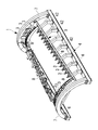
- the holding jig 1 which concerns on this embodiment is provided with the frame material 4, the supporting material 5, and the holding part 3 grade
- the body panel 10 is held by the holding jig 1, the body panel 10 is held so as to be convex upward.
- the frame member 4 is composed of two straight horizontal members 6 extending in one direction, and two arch members 7 disposed between the two horizontal members 6 and formed in an arch shape.
- the horizontal members 6 and the arch members 7 of the frame member 4 support a support member 5 described later.
- the horizontal members 6 are disposed, for example, parallel to the axial direction of the fuselage panel 10 along the axial direction of the fuselage panel 10 installed in the holding jig 1.
- the lower end of the arch member 7 is coupled to one end and the other end of the horizontal member 6.
- the holding jig 1 has a substantially wedge shape by the two horizontal members 6 and the two arch members 7.
- the girder member which couples one end or the other end of the two horizontal members 6 and extends in the vertical direction with respect to the horizontal member 6 is not provided.
- the length of the horizontal members 6 is longer than the axial length of the fuselage panel 10 manufactured by riveting, and the arrangement distance between the two horizontal members 6 is greater than the chordal length of the fuselage panel 10 manufactured by riveting Too long.
- the arch member 7 is a frame member 4 having a curved shape, and is disposed in a plane perpendicular to the axial direction of the fuselage panel 10 installed in the holding jig 1.
- the arch members 7 are provided one each on one end side and the other end side of the horizontal member 6 and are coupled to the two horizontal members 6.
- the frame member 4 has a configuration in which the horizontal member 6 and the arch member 7 are integrated.
- the curved shape, for example, the curvature, of the arch member 7 is provided substantially corresponding to the curvature of the body panel 10 to be manufactured.
- the support member 5 is disposed between two straight lower end support members 8 extending in the machine axis direction and the two lower end support members 8 and has two arched side end support members 9 and the like. It consists of
- the lower end support 8 supports the lower end of the fuselage panel 10 via the grip 3.
- the lower end support member 8 is located above the horizontal member 6 of the frame member 4 and is parallel to, for example, the axial direction of the fuselage panel 10 along the axial direction of the fuselage panel 10 installed in the holding jig 1. Or it is arranged to be in an oblique direction.
- the lower end support members 8 are arranged corresponding to the two opposing sides of the body panel 10 installed in the holding jig 1. For example, the lower end support 8 is disposed along the ends of the straight two opposing sides of the fuselage panel 10.
- the body panel 10 to be manufactured is a single curved surface all having the same curvature along the machine axis direction
- the body panel 10 is a holding jig 1 so that the machine axis of the body panel 10 is parallel to the horizontal plane.
- the lower end support 8 and the horizontal member 6 extend in parallel directions.
- the body panel 10 to be manufactured is a double curved surface whose curvature changes along the machine axis direction
- the body panel 10 is installed on the holding jig 1 so that the machine axis of the body panel 10 is parallel to the horizontal plane.
- the extending direction of the lower end support member 8 is oblique to the extending direction of the horizontal member 6.
- the machine axis of the body panel 10 is inclined to the horizontal plane, and the top of the body panel 10 on the holding jig 1 is parallel to the horizontal plane along the machine axis direction.
- the body panel 10 may be installed on the holding jig 1 so as to be substantially parallel. That is, the fuselage panel 10 is installed on the holding jig 1 such that the center on the smaller radius side of the cross section of the fuselage panel 10 is higher than the center on the larger radius side. As a result, the distances from the portal automatic drill 22 to the fuselage panel 10 become substantially equal in the axial direction of the fuselage panel 10.
- this invention is not limited to this example, You may make the radius of two arch materials 7 different.
- the lower end support 8 is supported by the horizontal member 6 via, for example, an auxiliary member 42 provided between the lower end support 8 and the horizontal member 6.
- the auxiliary member 42 is a member having one end connected to the horizontal member 6 and the other end connected to the lower end support 8, and a plurality of auxiliary members 42 are arranged along the longitudinal direction of the horizontal member 6 and the lower end support 8. .
- a plurality of grips 3 are arranged on the lower end support 8 at intervals.
- the length of the lower end support 8 is longer than the length in the machine axial direction of the body panel 10 to be manufactured, and the arrangement distance between the two lower end supports 8 is longer than the chord length of the body panel 10 to be manufactured.
- the lower end support member 8 is positioned lower than the held body panel 10 so that the grip portion 3 supports the lower end portion of the body panel 10 from the lower side.
- the lower end of the side end support 9 is coupled to one end and the other end of the lower end support 8 in the longitudinal direction.
- the side end support 9 supports the side end of the fuselage panel 10 via the grip 3.
- the side end support 9 is a member having a curved shape, and is disposed in a plane perpendicular to the axial direction of the fuselage panel 10 installed in the holding jig 1.
- the side end support members 9 are disposed corresponding to the two opposing sides of the body panel 10 installed in the holding jig 1.
- the side end supports 9 are provided respectively on one end side and the other end side of the lower end support 8 in the longitudinal direction, and are connected to the two lower end supports 8.
- the support 5 has a configuration in which the lower end support 8 and the side end support 9 are integrated.
- the curved shape, for example, the curvature, of the side end support 9 is provided corresponding to the curvature of the body panel 10 to be manufactured.
- a plurality of gripping portions 3 having the same configuration as the gripping portions 3 described above may be provided on the side end support members 9, and the gripping portions 3 may grip and support the side edge of the body panel 10.
- the plurality of gripping portions 3 provided on the side end support members 9 are provided at intervals corresponding to the curvature of the body panel 10 to be manufactured. Therefore, when the plurality of grips 3 grip the body panel 10, the body panel 10 gripped by the grips 3 is held so as to have the curvature of the body panel 10 to be manufactured.
- the curvature connecting the plurality of grips 3 in the side end support 9 on one end side and the other side is the same.
- the curvature connecting the plurality of grip portions 3 in the side end support member 9 on one end side is a plurality of sides on the other end side It becomes larger than the curvature which ties the holding part 3 in the end support material 9.
- the holding jig 1 since the holding jig 1 has the plurality of gripping portions 3 and the plurality of gripping portions 3 grip only the peripheral portion of the body panel 10, the shape of the peripheral portion where accuracy is required in assembly is appropriately set. Since it is possible to omit the structural member for supporting the central portion of the body panel 10 in the structure of the holding jig 1 while maintaining it, the weight of the holding jig 1 can be reduced. Thereby, the power accompanying the movement of the holding jig 1 can be reduced. Further, by omitting the structural member for supporting the central portion of the body panel 10 in the structure of the holding jig 1, the interference between the automatic hammer and the holding jig 1 can be reduced, and the automatic hammer can be applied. The scope can be expanded.
- the body panel 10 having a convex curve shape is held and supported by the lower peripheral edge portion, the body panel 10 with small rigidity can be stably held. As a result, it is possible to omit the structural member for supporting the central portion of the body panel 10 in the structure of the holding jig 1 while appropriately maintaining the shape of the peripheral portion that requires accuracy in assembly.
- the frame members 4 (or one of the arch members 7 among the frame members 4) are shared, thereby holding the holding jigs.
- the outer shape of 1 is standardized.
- the support member 5, the lower end support member 8 and the side end support members 9 installed in the holding jig 1 are installed so as to correspond to the shape of the body panel 10 inside the common outer shape. .
- the body panel 10 is installed on the holding jig 1 so as not to affect the outer shape of the holding jig 1.
- the outer shape of the holding jig 1 is made common, and the support member 5, the lower end support member 8 and the side end support member 9 are installed according to the shape of the body panel 10.
- the body panels 10 of various types can be transported on the same line.
- an initial shape holding jig 51 used in combination with the holding jig 1 described above will be described.
- the initial shape holding jig 51 is used. That is, the initial shape holding jig 51 is mounted on the fixing base 60 in the divided panel mounting space 11, and the initial shape holding jig 51 installed below the holding jig 1 is the body panel 10. It supports from the lower surface side and maintains the shape of the fuselage panel 10.
- segmentation panel 31 is a member before the fuselage
- the divided panel 31 is, for example, a member which is long in a direction parallel to the machine axis direction and divided into a plurality of parts in the circumferential direction of the body panel 10.
- the division panel 31 is obtained by, for example, dividing the body panel 10 into four in the circumferential direction.
- the initial shape holding jig 51 includes a pedestal 52, a support member 53, a shape holding portion 54 and the like.
- the pedestal portion 52 is, for example, two horizontal members 55 disposed parallel to the mechanical axis direction of the fuselage panel 10 and the horizontal member 55 along the machine axis direction of the body panel 10 installed in the holding jig 1. And the like.
- the horizontal member 55 of the pedestal 52 is a long member whose upper surface has a surface horizontal to the installation surface.
- the two horizontal members 55 are parallel to one another.
- the horizontal member 55 is supported by the structure 56.
- a plurality of support members 53 are provided on the upper surface of the horizontal member 55 of the pedestal portion 52.
- a rail 57 is provided which allows the support member 53 to move along the longitudinal direction of the horizontal member 55, ie, the longitudinal direction of the horizontal member 55.
- a traveling portion 58 for traveling the rail 57 is provided on the lower surface of the support member 53.
- the structures 56 of the pedestal portion 52 are erected in the vertical direction from the upper surface of the fixing base 60, and a plurality of pillars 62 arranged at intervals along the machine axis direction and a plurality of pillars 62 are coupled And the diagonal members 64 disposed in an oblique direction.
- the structure 56 is not limited to the illustrated example, but may support part of the weight of the supporting member 53 placed on the pedestal 52 and part of the weight of the body panel 10 transmitted through the supporting member 53. , May be other configurations.
- the initial shape holding jig 51 has a substantially wedge shape by the two horizontal members 55 and the plurality of support members 53.
- one end or the other end of the two horizontal members 55 are joined, and extended in the vertical direction to the horizontal member 55 as in the holding jig 1.
- Existing girder material is not provided. Thereby, when the body panel 10 is provided in the holding jig 1, it is possible to secure a work space which can pass along the machine axis direction at the lower part of the body panel 10 without being disturbed by the girder members.
- the length of the horizontal members 55 is longer than the axial length of the fuselage panel 10 manufactured by riveting, and the arrangement distance between the two horizontal members 55 is greater than the chordal length of the fuselage panel 10 manufactured by riveting Too long.
- the support member 53 is a member having an arc shape, and is disposed in a plane perpendicular to the axial direction of the fuselage panel 10 installed in the holding jig 1.
- four supports 53 are provided on the upper surface of the horizontal member 55 in the example shown in FIG. 6.
- the curved shape, for example, the curvature, of the support member 53 is provided substantially corresponding to the curvature of the body panel 10 to be manufactured.
- the distance between the plurality of support members 53 is determined in accordance with the size, shape, and the like of the body panel 10 to be held.
- the support member 53 is provided with a plurality of shape holding portions 54 at intervals along the circumferential direction.
- the shape holding portion 54 supports the fuselage panel 10 from below.
- the plurality of shape holding portions 54 supporting the body panel 10 holds the body panel 10 so as to have a shape formed at the time of completion when the rivet fastening operation is performed to overlap the divided panels 31.
- the shape holding portion 54 is in contact with the lower surface of the body panel 10, and has a configuration in which the position of the upper surface of the shape holding portion 54 supporting the body panel 10 can be adjusted.
- the holding jig 1 supports the fuselage panel 10 at the end of the fuselage panel 10. That is, in the body panel 10 having the skin 33, the ends of two opposing sides (for example, two opposing sides parallel to the machine axis direction) of the body panel 10 are gripped by the plurality of gripping portions 3. At this time, the plurality of grips 3 are integrally supported via the support members 5 provided corresponding to the body panel 10.
- the fuselage panel 10 is held so that the cross section cut in the direction perpendicular to the machine axis direction has a curved shape and the upper side is convex. Since the fuselage panel 10 is held from the lower side of the fuselage panel 10 at the ends of the two sides of the fuselage panel 10, for example, the holding jig 1 can hold the fuselage panel 10 with a simple structure. In addition, the holding jig 1 can be transported in a state of holding the body panel 10, for example, the frame 4 and the support 5 are integrated, and the bottom of the horizontal member 6 can be contained in the same plane. Since the holding jig 1 holds the body panel 10, it can be conveyed.
- the holding jig 1 Since the holding jig 1 has a structure for supporting the body panel 10 at the end of the body panel 10, it can correspond to each of a plurality of frames installed on the body panel 10 as in the conventional jig. In comparison with a jig provided with a plurality of positioning members, the structure is simplified and reduced in weight. Therefore, in a state in which the body panel 10 is held with respect to the holding jig 1, the body panel 10 is movable together with the holding jig 1. As a result, while moving the work place where the holding jig 1 is different, the riveting operation is performed by the automatic hammer on the fuselage panel 10, the riveting operation is performed manually, or the inspection and rework is performed. Work can be done.
- the initial shape holding jig 51 even when the rigidity of the body panel 10 is low, for example, when overlapping the end portions of the divided panels 31, the shape accuracy of the body panel 10 can be secured.
- the holding jig 1 can be simplified.
- the movable structure of the support member 53 and the shape holding portion 54 it is possible to correspond to the shapes of a plurality of types of body panels 10, and the initial shape holding jig 51 can be shared.
- the fuselage panel manufacturing method concerning this embodiment, after being divided by a rivet by a plurality of division panels 31 which constitute fuselage panel 10 by a superposition part, it is moved to a different place, and skin of fuselage panel 10 Alternatively, the frame 32 is attached by rivets to the stringer. As a result, the frame 32 is fixed to the skin after the shape of the skin of the fuselage panel 10 is fixed, so that it is possible to simultaneously attach the frame 32 to the skin or stringer while overlapping the ends of the skins. An accurate fuselage panel 10 can be manufactured.
- the fuselage panel 10 with high accuracy can be manufactured using the simple holding jig 1 in the above-mentioned order, fastening is performed using the portal automatic tapping machine 22 and the automatic tapping machine 25 instead of manual rivet fastening. By doing this, labor saving of work can be achieved. And since the lightweight holding jig 1 is moved, the motive power required for conveyance of the holding jig 1 can be suppressed.
- buffer spaces 13 and 17 are provided after the rivet setting operation by the automatic tapping machine. And, when the holding jig 1 is fixed there, the automatic hammering machine 22 and the automatic hammering machine 25 can be moved from the automatic hammering space 12, 16 to the buffer space 13, 17, It is also possible that the automatic tapping machine 22 and the automatic tapping machine 25 carry out the connection of the rivets in the buffer spaces 13, 17. As a result, it is possible to absorb the time difference of the working time caused by the type of aircraft panel.
- the transfer track 2 is provided, and the holding jig 1 moves in one direction along the transfer track 2, and in each work space, the holding jig 1 is fixed and rivets are applied to the body panel 10 Fastening work etc. are performed. That is, while the work is performed, the body panel 10 is fixed, and the body panel 10 moves only when being transported between the work spaces.
- the moving method and the process procedure of the holding jig 1 do not need to be changed according to the type of the body panel 10, so that all types of the body panel 10 can be manufactured on the same production line.
Landscapes
- Engineering & Computer Science (AREA)
- Mechanical Engineering (AREA)
- Aviation & Aerospace Engineering (AREA)
- Manufacturing & Machinery (AREA)
- Transportation (AREA)
- Automatic Assembly (AREA)
Abstract
航空機パネルを精度良く組み立てることが可能な航空機パネル製造方法及び航空機パネル製造システムを提供することを目的とする。航空機パネル製造方法は、保持治具(1)が、断面が曲線形状を有する複数の板状部材を有する胴体パネル(10)を、胴体パネル(10)の断面が上に凸の曲線形状となるように保持するステップと、保持治具(1)に保持された胴体パネル(10)の複数の板状部材同士を重ね合わせてリベットによって重なり部分を結合するステップと、複数の板状部材同士が結合された胴体パネル(10)が保持された保持治具(1)を移動するステップと、移動された保持治具(1)に保持された胴体パネル(10)の複数の板状部材に対し、胴体パネル(10)の曲線形状に沿ったフレーム(32)をリベットによって結合するステップとを有する。
Description
本発明は、航空機パネル製造方法及び航空機パネル製造システムに関するものである。
航空機の胴体パネルは、曲面を有する板状のスキンと、胴体の長手方向に沿ってスキンに設けられる長尺状のストリンガーと、胴体の周方向に沿って設けられるフレームなどが組み合わされて構成される。
隣り合うスキン同士の重なり部分の結合や、スキン又はストリンガーに対するフレームの結合は、位置決め治具を用いて、各部品の位置を正確に決定してから行われている。部品間の結合はリベットが使用される。剛性の高い位置決め治具を用いることにより、剛性が低いスキンに対して正確な位置で各部品を結合できる。
従来、位置決め治具は、工場内の所定位置に固定されて用いられており、上述のスキン同士の結合やフレームの結合は所定位置で行われて胴体パネルが製造されている。製造中の胴体パネルは、一の工程の作業場所から次工程の作業場所へ移動される場合に、位置決め治具から取り外されて移動されており、位置決め治具自体が移動することはなかった。
"大型ジェット旅客機ボーイング「777」ができるまで…(1)[岐阜工場・名古屋第一工場編]胴体パネルをつくる",Kawasaki News,川崎重工業株式会社 広報室,2005年4月,第138号,p.1-7
所定位置に固定されて用いられている位置決め治具は、製造される胴体パネルの形状に応じて予め製作されている。胴体パネルは、長手方向が直線である単曲面の場合だけでなく、長手方向にも曲率を有する複曲面の場合もある。そのため、胴体パネルの形状に応じて、多数の種類の位置決め治具を製作しておく必要があり、治具の製作や管理にかかるコストも高くなる。
胴体パネルの製造工程において、リベットの締結作業を行う際、手作業による打鋲によって、隣り合うスキン同士の重なり部分の結合や、スキン又はストリンガーに対するフレームの結合を行っている。近年になって、これらの工程に自動打鋲機も採用されている。しかし、位置決め治具に固定されたパネルへの打鋲する際、自動打鋲機が、パネルを支持する位置決め治具の支持部材と干渉する場合があるため、自動打鋲機を適用できる範囲には限りがあった。
また、胴体パネルを一の工程の作業場所から次工程の作業場所へ移動する際に、一の工程の作業場所の位置決め治具から取り外し、次工程の作業場所の位置決め治具への取り付けを行う必要があり、工程間移動に伴う作業を要する。また、従来の位置決め治具は、胴体パネルのフレームの間隔に対応して多数の位置決め材が配置されているため、自動打鋲機を適用できる範囲が限られている。そのため、自動打鋲機を用いて締結できるリベット数の割合が全体のリベット数に比べて少なかった。
本発明は、このような事情に鑑みてなされたものであって、治具の製作や管理を簡素化し、かつ、治具の製作や管理にかかるコストを抑制することが可能な航空機パネル製造方法及び航空機パネル製造システムを提供することを目的とする。
本発明の第1態様に係る航空機パネル製造方法は、保持治具が、断面が曲線形状を有する複数の板状部材を有する航空機パネルを、前記航空機パネルの断面が上に凸の曲線形状となるように保持するステップと、前記保持治具に保持された前記航空機パネルの前記複数の板状部材同士を重ね合わせてリベットによって重なり部分を結合するステップと、前記複数の板状部材が結合された前記航空機パネルが保持された前記保持治具を移動するステップと、移動された前記保持治具に保持された前記航空機パネルの前記複数の板状部材に対し、前記航空機パネルの曲線形状に沿った曲線部材をリベットによって結合するステップとを有する。
この構成によれば、航空機パネルを構成する複数の板状部材が、重なり部分でリベットによって締結された後、異なる場所に移動され、航空機パネルの板状部材に対してリベットによって曲線部材が取り付けられる。
上記第1態様において、前記複数の板状部材同士の重なり部分をリベットによって結合するステップと、前記航空機パネルが保持された前記保持治具を移動するステップと、曲線部材をリベットによって結合するステップとを通じて、前記航空機パネルが前記保持治具に保持された状態を維持する。
この構成によれば、各工程を通じて保持治具に航空機パネルが保持された状態を維持して保持治具を移動させるので、位置決め治具からの取り外し作業や位置決め治具への取り付け作業を省くことが可能となる。
上記第1態様において、前記保持治具が航空機パネルを保持するステップにおいては、前記保持治具は複数の把持部を有し、前記複数の把持部が前記複数の板状部材の周縁部のみを把持して前記航空機パネルを保持してもよい。
この構成によれば、組み立てにおいて精度が要求される周縁部の形状を適切に維持しつつ、保持治具の構造において板状部材の中央部を支持する構造部材を省くことができるため、保持治具の重量を軽量化することができる。これにより保持治具の移動に伴う動力を低減することができる。また、保持治具の構造において板状部材の中央部を支持する構造部材を省くことで、自動打鋲機と保持治具との干渉を減らすことができ、自動打鋲機の適用できる範囲を拡げることができる。
上記第1態様において、前記保持治具は、前記航空機パネルの対向する2辺の端部を把持する複数の把持部を有し、前記複数の把持部が前記複数の板状部材の周縁部を把持して前記航空機パネルを保持してもよい。上記第1態様において、前記対向する2辺は、前記航空機パネルの上に凸の曲線形状を有する断面に垂直な方向に延在する2辺であり、前記保持治具に保持された状態で航空機パネルの下側周縁部となる。
この構成によれば、上に凸の曲線形状を有する前記航空機パネルを下側周縁部で把持して支えることとなるため、剛性の小さい航空機パネルを安定して保持できる。これにより組み立てにおいて精度が要求される周縁部の形状を適切に維持しつつ、保持治具の構造において板状部材の中央部を支持する構造部材を省くことができる。
上記第1態様において、前記複数の板状部材同士の重なり部分をリベットによって結合するステップと、曲線部材をリベットによって結合するステップの少なくともいずれか一方において、前記リベットの結合は、自動打鋲機が行う。
この構成によれば、上述の順番によって精度の良い航空機パネルを製造できることから、手動によるリベット締結ではなく、自動打鋲機を用いて締結することで作業の省力化を図ることができる。
上記第1態様において、前記複数の板状部材同士の重なり部分をリベットによって結合するステップと、曲線部材をリベットによって結合するステップの少なくともいずれか一方の後で、バッファスペースに前記保持治具を固定するステップを更に備え、前記バッファスペースにて、前記自動打鋲機が前記リベットの結合を行う。
この構成によれば、自動打鋲機によるリベット締結作業の後に、バッファスペースが設けられ、保持治具がそこで固定され、場合によっては、自動打鋲機がリベットの結合を行うことから、航空機パネルの種類によって生じる作業時間の時間差を吸収できる。
上記第1態様において、前記保持治具は、搬送用軌道に沿って一方向に移動し、前記複数の板状部材同士の重なり部分をリベットによって結合するステップと、前記曲線部材をリベットによって結合するステップとでは、前記保持治具が各加工スペースで固定されている。
この構成によれば、搬送用軌道が設けられて、搬送用軌道に沿って保持治具が一方向に移動し、各作業スペースでは、保持治具が固定されて、航空機パネルに対しリベット締結作業等が行われる。すなわち、作業が行われる間は、航空機パネルが固定され、作業スペース間で搬送されるときのみ航空機パネルが移動する。
上記第1態様において、前記保持治具は、前記航空機パネルの対向する2辺の端部を把持する複数の把持部と、前記複数の把持部によって把持される前記航空機パネルに対応して設けられ、前記複数の把持部を一体的に支持する支持材とを備え、前記支持材は、一軸方向に沿って、前記航空機パネルの対向する2辺の各辺に対応して1本ずつ設けられる第1枠材を有し、前記第1枠材に支持された前記複数の把持部は、前記一軸方向に沿った前記航空機パネルの対向する2辺の端部で前記航空機パネルを把持しつつ、前記一軸方向に対して垂直方向に切断した断面が、上側に凸の曲線形状となるように前記航空機パネルを保持し、前記航空機パネルを保持した状態で搬送され得る構成を有する。
従来は、複雑な構造を有する治具によって、一箇所の作業スペースで、複数の隣り合うスキン同士を重ね合わせながら、フレームをスキンやストリンガーに取り付けていた。しかし、航空機パネルの板状部材の両端部を保持し、かつ、板状部材の断面が上に凸の曲線形状となるように保持する治具であるため、その後の別の工程で、他の曲線部材(例えばフレーム)を、板状部材(例えばスキン)、又は、スキンに設けられたストリンガーに取付けることができる。よって、簡素な治具で航空機パネルの組み立てを行うことができる。
本発明の第2態様に係る航空機パネル製造方法は、複数種類の航空機パネルを同じライン上で製造する航空機パネル製造方法であって、前記航空機パネルを構成する複数の板状部材を保持治具に載置し、前記航空機パネルの周縁部を把持して前記保持治具上に固定するステップと、前記保持治具を第一の加工エリアに搬送するステップと、前記第一の加工エリアで、前記複数の板状部材同士を重ね合わせて仮留めして、前記航空機パネルの断面が上に凸の曲線形状となるように保持するステップと、前記航空機パネルが載置された前記保持治具を前記第一の加工エリアから第二の加工エリアに搬送するステップと、前記第二の加工エリアで、前記複数の板状部材同士の重なり部分をリベットによって結合するステップとを有し、前記保持治具上に固定するステップでは、前記複数の板状部材の長手方向の周縁部のみを把持して固定し、前記保持治具は、前記第一の加工エリアと前記第二の加工エリアの間を、前記航空機パネルを把持した状態を維持して移動することを特徴とする。
本発明の第3態様に係る航空機パネル製造方法は、複数種類の航空機パネルを同じライン上で製造する航空機パネル製造方法であって、前記航空機パネルを構成する複数の板状部材を保持治具に載置し、前記航空機パネルの周縁部を把持して前記保持治具上に固定するステップと、前記保持治具を第一の加工エリアに搬送するステップと、前記第一の加工エリアで、前記保持治具と、第一の加工エリアに設置された形状保持治具とを組み合わせるステップと、前記形状保持治具によって、前記複数の板状部材の形状の調整を行うステップと、前記複数の板状部材同士を重ね合わせて仮留めして、前記航空機パネルの断面が上に凸の曲線形状となるように保持するステップと、前記航空機パネルが載置された前記保持治具を前記第一の加工エリアから第二の加工エリアに搬送するステップと、前記第二の加工エリアで、前記複数の板状部材同士の重なり部分をリベットによって結合するステップとを有する。
本発明の第4態様に係る航空機パネル製造方法は、複数種類の航空機パネルを同じライン上で製造する航空機パネル製造方法であって、第一の加工エリアで、前記航空機パネルを構成する複数の板状部材同士を重ね合わせて仮留めして、前記航空機パネルの断面が上に凸の曲線形状となるように保持するステップと、前記航空機パネルが載置された前記保持治具を前記第一の加工エリアから第二の加工エリアに搬送するステップと、前記第二の加工エリアで、前記複数の板状部材同士の重なり部分をリベットによって結合するステップと、前記航空機パネルが載置された前記保持治具を前記第二の加工エリアから第三の加工エリアに搬送するステップと、前記第三の加工エリアで、前記保持治具上の前記航空機パネルに他の部材を取り付けるステップとを有する。
本発明の第5態様に係る航空機パネル製造方法は、複数種類の航空機パネルを同じライン上で製造する航空機パネル製造システムであって、第一の加工エリアと第二の加工エリアの間を、前記航空機パネルを把持した状態を維持して移動する保持治具と、前記第一の加工エリアに設置され、前記保持治具と組み合わせて用いられる形状保持治具と、前記第二の加工エリアに設置され、前記保持治具上の前記航空機パネルに対しリベットの締結を行う打鋲装置とを備え、前記保持治具は、前記複数種類の航空機パネルに共通する共通部分を有する治具枠と、前記治具枠の内側に設けられた支持材と、前記支持材に設けられ、前記航空機パネルの長手方向の周縁部を把持する把持部とを有し、前記把持部のみによって、前記航空機パネルの断面が上に凸の曲線形状となるように保持する。
本発明によれば、航空機パネルのうち板状部材の形状が定まった後、曲線部材が板状部材に固定されることから、簡素な治具で組立を行うことができ、治具の製作や管理を簡素化し、かつ、治具の製作や管理にかかるコストを抑制することができる。また、リベットの締結作業について、自動打鋲機を適用できる範囲を増加させることができる。
以下に、本発明に係る実施形態について、図面を参照して説明する。図1から図3は、本発明の一実施形態に係る胴体パネル製造システムを示す斜視図である。図1及び図2において、矢印Aでは搬送用軌道2が連続していることを示し、図2及び図3において、矢印Bでは搬送方法が変更されることを示している。
まず、本発明の一実施形態に係る胴体パネル製造システムについて説明する。
胴体パネル製造システムは、図1及び図2に示すように、胴体パネル10が保持される保持治具1と、保持治具1が搬送される搬送用軌道2を備える。本実施形態では、搬送用軌道2は、複数の作業スペースを通過するように一方向に形成される。
胴体パネル製造システムは、図1及び図2に示すように、胴体パネル10が保持される保持治具1と、保持治具1が搬送される搬送用軌道2を備える。本実施形態では、搬送用軌道2は、複数の作業スペースを通過するように一方向に形成される。
胴体パネル10は、航空機の略円筒形状の胴体部分が、機軸方向及び周方向に分割された形状である。したがって、胴体パネル10は、機軸方向に対して垂直方向の断面が円弧形状を有する。胴体パネル10において、機軸方向に対して平行又は斜めの対向する2辺は、直線であり、保持治具1によって胴体パネル10が保持されたとき、胴体パネル10の下端に位置する。また、胴体パネル10において、機軸方向に対し垂直な面に収まる対向する2辺は、円弧形状であり、保持治具1によって胴体パネル10が保持されたとき、胴体パネル10の側端に位置する。
搬送用軌道2には、例えば、チェーンコンベヤ、ベルトコンベヤ等の搬送装置が設けられる。保持治具1は、搬送装置に載置されて、搬送用軌道2の一端側から他端側へ搬送される。搬送装置は、チェーン又はベルト等がモーターによって駆動され、チェーン又はベルト等は、保持治具1の水平材6に対して平行に巻かれて設けられる。
保持治具1は、例えば、アルミニウム製又はアルミニウム合金製である。保持治具1に胴体パネル10が保持されるとき、胴体パネル10は、上側に凸となるように保持される。なお、図示した保持治具1は、一例にすぎず、本発明で用いられる保持治具は、この構成を有するものに限定されない。
搬送用軌道2は、分割パネル取付けスペース11、スキン重ね合わせのための自動打鋲スペース12、バッファスペース13、手動打鋲スペース14、フレーム32を取り付けるためのフレーム取付けスペース15、フレーム32をスキン又はストリンガーに結合するための自動打鋲スペース16を、保持治具1が順に通過するように設けられている。分割パネル取付けスペース11、自動打鋲スペース12、バッファスペース13、手動打鋲スペース14、フレーム取付けスペース15、自動打鋲スペース16については、後述する。
なお、本実施形態では、分割パネル取付けスペース11には、分割パネル取付けロボット21が設置され、スキン重ね合わせのための自動打鋲スペース12には、門型フレームを備える門型自動打鋲機22が設置されている。また、フレーム取付けスペース15には、フレーム取付け用ロボット24が設置され、フレーム32をスキン又はストリンガーに結合するための自動打鋲スペース16には、自動打鋲機25が設置されている。
また、スキン重ね合わせのための自動打鋲スペース12には、複数、例えば3台の門型自動打鋲機22が設置されており、フレーム32をスキン又はストリンガーに結合するための自動打鋲スペース16には、複数、例えば2台の自動打鋲機25が設置されている。
次に、上述した胴体パネル製造システムを用いた胴体パネル10の製造方法について説明する。
まず、台車26に載置された保持治具1を搬送用軌道2まで移動させ、保持治具1を搬送用軌道2に移動させる。
次に、保持治具1を分割パネル取付けスペース11に移動し、保持治具1に胴体パネル10を保持させる。保持治具1が分割パネル取付けスペース11の所定位置に固定された後、取り付け作業が開始される。保持治具1に胴体パネル10を保持させる場合、まず、分割パネル取付けロボット21等によって、分割パネル31を保持治具1の所定位置に載置する。分割パネル31とは、胴体パネル10がリベットによって締結される前の部材であり、胴体パネル10が複数に分割された部材である。分割パネル31は、例えば機軸方向に対して平行方向に長く、胴体パネル10の周方向に複数に分割された部材である。分割パネル31は、胴体パネル10が例えば周方向に三つに分割されたものである。
胴体パネル10の分割パネル31は、保持治具1に設けられた把持部3によって固定される。なお、このとき、分割パネル31の形状を保持するため、保持治具1以外の初期形状保持治具51(図6参照)を用いて、胴体パネル10を下側から保持する。また、航空機のドアに該当する位置等であって、胴体パネル10に開口部が形成される場合、開口部の縁部に沿って開口部補強材(図示せず。)が設けられる。この場合、開口部補強材を保持する治具が、上述の初期形状保持治具51に設けられてもよい。初期形状保持治具51は、分割パネル取付けスペース11に固定されている。
複数の分割パネル31は、保持治具1に載置されたとき、保持治具1上で隣り合う分割パネル31同士のスキンが、端部近傍で重ね合わされる。すなわち、一つの分割パネル31のスキンの上に、他の分割パネル31のスキンが載置される。そして、スキン同士は、重なり合う部分が、リベットで仮留めされる。そして、仮留めされた胴体パネル10は、保持治具1に設けられた把持部3によって固定された状態が維持される。
仮留めされ、把持部3によって固定された胴体パネル10は、保持治具1に設置された状態で次工程の自動打鋲スペース12に移動される。保持治具1の移動は、例えば、保持治具1の底部に位置するコンベヤによって行われる。保持治具1を移動する際、初期形状保持治具51は胴体パネル10から外される。この状態でも、完成された胴体パネル10の形状が保持されるように、保持治具1は、胴体パネル10を固定している。
次に、保持治具1を自動打鋲スペース12に移動し、保持治具1に載置された隣り合う分割パネル31のスキン同士をリベットによって締結する。保持治具1が自動打鋲スペース12の所定位置に固定された後、打鋲作業が開始される。隣り合うスキン同士の重なり部分を結合するための門型自動打鋲機22は、保持治具1をまたぐように設置され、門型自動打鋲機22は、保持治具1に載置された分割パネル31の上方から下方に向けて打鋲を行う。
門型自動打鋲機22は、胴体パネル10の半径方向に打鋲が可能である。門型自動打鋲機22は、連続的にリベットを締結する。これにより、胴体パネル10の半径方向に打鋲が行われ、隣り合う分割パネル31が重ね合わせ部分で結合される。
また、門型自動打鋲機22は、保持治具1及び胴体パネル10の機軸方向、すなわち、搬送用軌道2に対して平行に移動可能であり、門型自動打鋲機22が、固定された保持治具1及び胴体パネル10の機軸方向に沿って移動する。したがって、保持治具1を固定したまま、門型自動打鋲機22が移動することにより、1領域の重ね合わせ部分の打鋲が完了した後、他の領域の重ね合わせ部分の打鋲を行うことができる。
打鋲が完了した胴体パネル10は、保持治具1に設置された状態で、隣の自動打鋲スペース12に移動される。保持治具1の移動は、例えば、保持治具1の底部に位置するコンベヤによって行われる。
自動打鋲スペース12は、例えば3箇所設けられ、それぞれに1台の門型自動打鋲機22が設けられることで、合計3台の門型自動打鋲機22が設置される。また、自動打鋲スペース12の下流側には、バッファスペース13が少なくとも1箇所設けられる。3箇所の自動打鋲スペース12と1箇所のバッファスペース13には、胴体パネル10を1台ずつ設置できる。門型自動打鋲機22をバッファスペース13に移動させることもでき、バッファスペース13において、胴体パネル10に対して、門型自動打鋲機22によるリベット締結作業を行うこともできる。また、3台の門型自動打鋲機22が打鋲するリベットの種類を異ならせることで、1台の門型自動打鋲機22においてリベットの種類を交換する場合に比べて、交換作業の手間を省略することができる。
自動打鋲スペース12で自動打鋲が完了した後は、保持治具1をバッファスペース13に移動し、手動打鋲スペース14で作業員による打鋲が行われるまで、胴体パネル10が設置された保持治具1を一時的に固定しておいてもよい。バッファスペース13を設けておくことで、自動打鋲スペース12や手動打鋲スペース14などそれぞれにおける作業時間の時間差を吸収でき、順番待ちによって生産ラインの中で作業が行われないスペースを減らすことができる。
次に、保持治具1を手動打鋲スペース14に移動し、門型自動打鋲機22及び自動打鋲機25では打鋲しにくい部分のリベットの締結作業を行う。保持治具1が手動打鋲スペース14の所定位置に固定された後、作業員によって打鋲作業が開始される。
手動によるリベット締結作業は、例えば、胴体パネル10に取り付けられる航空機ドアのヒンジ取り付け、配線配管用ブラケット又はセンサ設置用ブラケットの取り付けなどに対して行われる。
手動打鋲スペース14は、例えば2箇所設けられる。すなわち、1箇所の手動打鋲スペース14で作業が完了した後、隣の手動打鋲スペース14へ保持治具1を移動させる。手動打鋲スペース14が複数に分けて設けられていることにより、手動によるリベット締結作業の作業量が多く、手動打鋲スペース14が1箇所のみでは対応できない胴体パネル10についても作業を完了させることができる。
手動打鋲スペース14での打鋲が完了した胴体パネル10は、保持治具1に設置された状態で、隣のフレーム取付けスペース15に移動される。保持治具1の移動は、前工程と同様に、例えば、保持治具1の底部に位置するコンベヤによって行われる。
フレーム取付けスペース15では、スキン又はストリンガーに対しフレーム32が取り付けられる。保持治具1が自動打鋲スペース16の所定位置に固定された後、打鋲作業が開始される。スキン又はストリンガーに対するフレーム32の取り付けは、例えばフレーム取付け用ロボット24によって行われる。フレーム取付け用ロボット24は、保持治具1に載置された胴体パネル10よりも下方に位置するように配置される。フレーム取付け用ロボット24は、取り付けるフレーム32を把持し、スキン又はストリンガーにおける所定位置まで搬送する。搬送されたフレーム32は、スキン又はストリンガーにおける所定位置でリベットによって仮留めされる。
フレーム32が仮留めされた胴体パネル10は、保持治具1に設置された状態で次工程の自動打鋲スペース16に移動される。保持治具1の移動は、例えば、保持治具1の底部に位置するコンベヤによって行われる。
次に、保持治具1を自動打鋲スペース16に移動し、保持治具1に載置された胴体パネル10のスキン又はストリンガーに対しフレーム32をリベットによって締結する。保持治具1が自動打鋲スペース16の所定位置に固定された後、打鋲作業が開始される。スキン又はストリンガーを結合するための自動打鋲機25は、保持治具1に載置された胴体パネル10よりも下方に位置するように配置される。自動打鋲機25は、例えば、保持治具1に載置された胴体パネル10のストリンガーと、ストリンガーに仮留めされたフレーム32に対し、フレーム32の板面に対してほぼ垂直方向(すなわち、胴体パネルのスキンの板面に対してほぼ平行方向)に向けてリベットを締結する。
保持治具1を固定したまま、自動打鋲機25が打鋲位置へ移動することにより、複数のフレーム32に対し打鋲を行うことができる。
打鋲が完了した胴体パネル10は、保持治具1に設置された状態で、隣の自動打鋲スペース16に移動される。
打鋲が完了した胴体パネル10は、保持治具1に設置された状態で、隣の自動打鋲スペース16に移動される。
自動打鋲スペース16は、例えば2箇所設けられ、例えば合計2台の自動打鋲機25が設置される。2台の自動打鋲機25が設置されることで、二つの胴体パネル10を同時に打鋲することができる。2台の自動打鋲機25が打鋲するリベットの種類を異ならせることで、1台の自動打鋲機25においてリベットの種類を交換する場合に比べて、交換作業の手間を省略することができる。また、自動打鋲スペース16で、自動打鋲機25による打鋲を行わない場合は、自動打鋲機25をバッファスペース17に移動させた後、自動打鋲スペース16で作業が完了しなかった胴体パネル10に対して、自動打鋲機25によるリベット締結作業を行うこともできる。
自動打鋲スペース16で自動打鋲が完了した後は、保持治具1をバッファスペース17に移動、又は、保持治具1を搬送用軌道2から台車26へ移動させる。これにより、保持治具1は、胴体パネル10が載置された状態で台車26に載せられ、胴体パネル10は、台車26と共に移動可能となる。
次に、保持治具1に載置された胴体パネル10を台車26によって検査・手直しスペース18に移動する。検査・手直しスペース18では、打鋲が完了した胴体パネル10について適切な打鋲が施されているか否かの検査が行われ、手直しが必要な場合は作業員によってリベットが取り外され再度リベットが締結される。
検査が完了した胴体パネル10は、保持治具1から、クレーン等によって吊り上げられて取り外される。保持治具1から取り外された胴体パネル10は、胴体パネル10の周方向に約90°回転されて、台車27に直接載置される。台車27に載置された胴体パネル10は、手作業スペース19に移動され、種々の手作業、例えば、フロアビームの取付け、ドアのはみ出し部分の切断、ドアヒンジの取付けなどが行われる。その後、サンディング・清掃スペース20に移動され、そこで、胴体パネル10に塗装を行う前の下地処理としてサンディングが行われ、胴体パネル10に表面処理が施される。
その後、胴体パネル10は、塗装スペース41に移動され、例えば塗装用ロボット28などによって胴体パネル10全体に塗装が施される。塗装が完了した胴体パネル10は、完成品として例えばコンテナ29に格納されて出荷される。
上述したとおり、複数の分割パネル31のスキン同士の重なり部分をリベットによって結合する工程と、胴体パネル10が保持された保持治具1を移動する工程と、フレーム32をリベットによって結合する工程とを通じて、胴体パネル10が保持治具1に保持された状態を維持する。これにより、各工程を通じて保持治具1に胴体パネル10が保持された状態を維持して保持治具1を移動させるので、位置決め治具からの取り外し作業や位置決め治具への取り付け作業を省くことが可能となる。
次に、本実施形態に係る胴体パネル製造システムで用いられる保持治具1の一例について説明する。
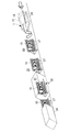
航空機の胴体パネル10は、図4に示すように、曲面を有する板状のスキン33と、胴体の機軸方向(長手方向)に沿ってスキン33に設けられる長尺状のストリンガー34と、胴体の周方向に沿って設けられるフレーム(図示せず。)などが組み合わされて構成される。胴体パネル10は、例えばアルミニウム製又はアルミニウム合金製であり、サイズの一例は、長手方向長さが10m、弦長さが6mであり、板厚が2mmから5mmである。
本実施形態に係る保持治具1が胴体パネル10を保持する工程において、胴体パネル10は、航空機の略円筒形状の胴体部分が、機軸方向及び周方向に分割された形状である。したがって、胴体パネル10は、機軸方向に対して垂直方向の断面が円弧形状を有する。胴体パネル10において、機軸方向に対して平行又は斜めの対向する2辺は、直線であり、保持治具1によって胴体パネル10が保持されたとき、胴体パネル10の下端に位置する。また、胴体パネル10において、機軸方向に対し垂直な面に収まる対向する2辺は、円弧形状であり、保持治具1によって胴体パネル10が保持されたとき、胴体パネル10の側端に位置する。
製造する航空機の胴体の機軸方向の一部分が、機軸方向に沿って曲率が全て同じである単曲面である場合、複数の胴体パネル10についても、機軸方向に沿って曲率が全て同じである。一方、製造する胴体パネル10が、機軸方向に沿って曲率が変化する複曲面である場合、下端支持材8の延在方向は、水平材6の延在方向に対し斜めである。
保持治具1は、搬送可能な構成を有しており、例えば、チェーンコンベヤ、ベルトコンベヤ等を備える搬送装置(図示せず。)に載置されて、一端側から他端側へ搬送される。搬送装置は、チェーン又はベルト等が保持治具1の水平材6に対して平行に巻かれて設けられ、チェーン又はベルト等は、モーターの駆動によって回転される。図4では、保持治具1は、固定台60に固定されている状態を示している。
保持治具1では、複数の把持部3は、支持材5によって支持され、相対位置が固定されて一体化されており、2本の水平材6の底部が同一面内に収まる形状を有する。これにより、保持治具1は、搬送装置によって搬送可能である。
本実施形態に係る保持治具1は、図4及び図5に示すように、枠材4と、支持材5と、把持部3などを備える。保持治具1に胴体パネル10が保持されるとき、胴体パネル10は、上側に凸となるように保持される。
枠材4は、一方向に延在する直線状の2本の水平材6と、2本の水平材6間に設置され、アーチ状に形成された2本のアーチ材7などからなる。枠材4の水平材6及びアーチ材7は、後述する支持材5を支持する。
水平材6は、保持治具1に設置される胴体パネル10の機軸方向に沿って、例えば、胴体パネル10の機軸方向に対して平行に配置される。水平材6の一端部と他端部には、アーチ材7の下端が結合して設けられる。これにより、保持治具1は、2本の水平材6と2本のアーチ材7とによって、ほぼ鞍形の形状を有する。
なお、本実施形態の保持治具1では、2本の水平材6の一端部同士又は他端部同士を結合し、水平材6に対し垂直方向に延在する桁材は、設けられない。これにより、保持治具1に胴体パネル10が設けられた場合において、胴体パネル10の下部で、桁材に妨害されることなく、機軸方向に沿って通過可能な作業空間を確保できる。
水平材6の長さは、リベット締結によって製造される胴体パネル10の機軸方向の長さよりも長く、2本の水平材6の配置間隔は、リベット締結によって製造される胴体パネル10の弦長さよりも長い。
アーチ材7は、曲線形状を有する枠材4であり、保持治具1に設置される胴体パネル10の機軸方向に対して垂直方向の面内に配置される。アーチ材7は、水平材6の一端側と他端側にそれぞれ一つずつ設けられ、2本の水平材6と結合される。これにより、枠材4は、水平材6とアーチ材7が一体化した構成を有する。アーチ材7の曲線形状、例えば曲率は、製造する胴体パネル10の曲率にほぼ対応して設けられる。
支持材5は、機軸方向に延在する直線状の2本の下端支持材8と、2本の下端支持材8間に設置され、アーチ状に形成された2本の側端支持材9などからなる。
下端支持材8は、把持部3を介して、胴体パネル10の下端を支持する。下端支持材8は、枠材4の水平材6よりも上方に位置し、保持治具1に設置される胴体パネル10の機軸方向に沿って、例えば、胴体パネル10の機軸方向に対して平行又は斜め方向になるように配置される。下端支持材8は、保持治具1に設置される胴体パネル10の対向する2辺の各辺に対応して配置される。例えば、下端支持材8は、胴体パネル10の直線状の対向する2辺の端部に沿うように配置される。
例えば、製造する胴体パネル10が、機軸方向に沿って曲率が全て同じである単曲面である場合、胴体パネル10の機軸が水平面に対して平行になるように、胴体パネル10が保持治具1に設置されたとき、下端支持材8と水平材6の延在方向は平行である。一方、製造する胴体パネル10が、機軸方向に沿って曲率が変化する複曲面である場合、胴体パネル10の機軸が水平面に対して平行になるように、胴体パネル10が保持治具1に設置されたとき、下端支持材8の延在方向は、水平材6の延在方向に対し斜めである。
また、製造する胴体パネル10が、複曲面である場合、胴体パネル10の機軸を水平面に対して斜めにして、保持治具1上における胴体パネル10の最上部が機軸方向に沿って水平面に対してほぼ平行になるように、胴体パネル10が保持治具1に設置されてもよい。すなわち、胴体パネル10の横断面のうち半径の小さい側の中心が、半径の大きい側の中心よりも高くなるように、胴体パネル10が保持治具1に設置される。これにより、門型自動打鋲機22から胴体パネル10までの距離が、胴体パネル10の機軸方向でほぼ等しくなる。
なお、2本のアーチ材7が同一半径を有する場合について例示したが、本発明はこの例に限定されず、2本のアーチ材7の半径を異ならせてもよい。
なお、2本のアーチ材7が同一半径を有する場合について例示したが、本発明はこの例に限定されず、2本のアーチ材7の半径を異ならせてもよい。
下端支持材8は、例えば、水平材6との間に設けられた補助材42を介して、水平材6によって支持される。補助材42は、一端部が水平材6と連結し、他端部が下端支持材8と連結する部材であり、水平材6及び下端支持材8の長手方向に沿って複数本が配置される。
下端支持材8には、複数の把持部3が互いに間隔を空けて配置される。下端支持材8の長さは、製造する胴体パネル10の機軸方向の長さよりも長く、2本の下端支持材8の配置間隔は、製造する胴体パネル10の弦長さよりも長い。また、把持部3が胴体パネル10の下端部を下方から支持するように、下端支持材8は、保持される胴体パネル10よりも下方に位置する。
下端支持材8の長手方向の一端部と他端部には、側端支持材9の下端が結合して設けられる。
下端支持材8の長手方向の一端部と他端部には、側端支持材9の下端が結合して設けられる。
側端支持材9は、把持部3を介して胴体パネル10の側端を支持する。側端支持材9は、曲線形状を有する部材であり、保持治具1に設置される胴体パネル10の機軸方向に対して垂直方向の面内に配置される。側端支持材9は、保持治具1に設置される胴体パネル10の対向する2辺の各辺に対応して配置される。
側端支持材9は、下端支持材8の長手方向の一端側と他端側にそれぞれ一つずつ設けられ、2本の下端支持材8と結合される。これにより、支持材5は、下端支持材8と側端支持材9が一体化した構成を有する。側端支持材9の曲線形状、例えば曲率は、製造する胴体パネル10の曲率に対応して設けられる。側端支持材9には、上述した把持部3と同様の構成を有する把持部3が複数設けられて、把持部3が胴体パネル10の側端を把持して支持してもよい。
このとき、側端支持材9に設けられる複数の把持部3は、製造する胴体パネル10の曲率に対応する位置に、互いに間隔を空けて設けられる。したがって、複数の把持部3が胴体パネル10を把持することで、把持部3によって把持された胴体パネル10は、製造する胴体パネル10の曲率となるように保持される。
例えば、製造する胴体パネル10が、機軸方向に沿って曲率が全て同じである単曲面である場合、一端側の側端支持材9における複数の把持部3を結ぶ曲率と、他端側の側端支持材9における複数の把持部3を結ぶ曲率は同じである。一方、製造する胴体パネル10が、一軸方向に沿って曲率が変化する複曲面である場合、一端側の側端支持材9における複数の把持部3を結ぶ曲率は、他端側の複数の側端支持材9における把持部3を結ぶ曲率よりも大きくなる。
上述したとおり、保持治具1は複数の把持部3を有し、複数の把持部3が胴体パネル10の周縁部のみを把持するため、組み立てにおいて精度が要求される周縁部の形状を適切に維持しつつ、保持治具1の構造において胴体パネル10の中央部を支持する構造部材を省くことができるため、保持治具1の重量を軽量化することができる。これにより保持治具1の移動に伴う動力を低減することができる。また、保持治具1の構造において胴体パネル10の中央部を支持する構造部材を省くことで、自動打鋲機と保持治具1との干渉を減らすことができ、自動打鋲機の適用できる範囲を拡げることができる。
また、上に凸の曲線形状を有する胴体パネル10を下側周縁部で把持して支えることとなるため、剛性の小さい胴体パネル10を安定して保持できる。これにより組み立てにおいて精度が要求される周縁部の形状を適切に維持しつつ、保持治具1の構造において胴体パネル10の中央部を支持する構造部材を省くことができる。
本実施形態では、同一の生産ラインを移動する複数の保持治具1において、枠材4(又は、枠材4のうちアーチ材7の1つ)が共通化されていることによって、保持治具1の外側の形状が共通化されている。また、保持治具1に設置される支持材5、下端支持材8及び側端支持材9は、共通化された外側形状よりも内側において、胴体パネル10の形状に対応するように設置される。これにより、胴体パネル10は、保持治具1の外側形状に影響を及ぼさないように、保持治具1に設置される。
保持治具1の外側の形状が共通化され、かつ、支持材5、下端支持材8及び側端支持材9は胴体パネル10の形状に応じて設置されていることから、本実施形態に係る保持治具1によれば、多品種の胴体パネル10を同一ラインで搬送可能である。また、支持材5、下端支持材8及び側端支持材9の設置位置を異ならせるだけで、航空機の仕様変更に伴う胴体パネル10の形状の変更に対応可能である。
次に、上述した保持治具1と組み合わせて用いられる初期形状保持治具51について説明する。
分割パネル取付けスペース11にて、複数の分割パネル31が、分割パネル取付けロボット21によって、保持治具1に載置される際に初期形状保持治具51が用いられる。すなわち、初期形状保持治具51は、分割パネル取付けスペース11において、固定台60に載置されており、保持治具1よりも下方に設置される初期形状保持治具51は、胴体パネル10を下面側から支持し、胴体パネル10の形状を保持する。
分割パネル取付けスペース11にて、複数の分割パネル31が、分割パネル取付けロボット21によって、保持治具1に載置される際に初期形状保持治具51が用いられる。すなわち、初期形状保持治具51は、分割パネル取付けスペース11において、固定台60に載置されており、保持治具1よりも下方に設置される初期形状保持治具51は、胴体パネル10を下面側から支持し、胴体パネル10の形状を保持する。
なお、分割パネル31とは、胴体パネル10がリベットによって締結される前の部材であり、胴体パネル10が複数に分割された部材である。分割パネル31は、例えば機軸方向に対して平行方向に長く、胴体パネル10の周方向に複数に分割された部材である。分割パネル31は、胴体パネル10が例えば周方向に四つに分割されたものである。
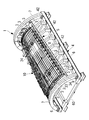
本実施形態に係る初期形状保持治具51は、図6に示すように、台座部52と、支持材53と、形状保持部54などを備える。
台座部52は、保持治具1に設置される胴体パネル10の機軸方向に沿って、例えば、胴体パネル10の機軸方向に対して平行に配置される2本の水平材55と、水平材55を支持する構造体56などを有する。
台座部52の水平材55は、上面が設置面に対して水平な面を有する長尺状部材である。2本の水平材55は互いに平行である。水平材55は、構造体56によって支持される。台座部52の水平材55の上面には、複数の支持材53が設置される。また、水平材55の上面には、支持材53を機軸方向、すなわち、水平材55の長手方向に沿って移動可能にするレール57が設けられる。支持材53の下面にはレール57を走行する走行部58が設けられる。
台座部52の構造体56は、固定台60の上面から鉛直方向に立設され、機軸方向に沿って、間隔を空けて複数本配置された柱材62や、複数の柱材62間を結合する桁材63や、斜め方向に配置される斜材64などを有する。なお、構造体56は、図示した例に限定されず、台座部52に載置される支持材53の重量や、支持材53を介して伝達される胴体パネル10の重量の一部を支持できれば、他の構成であってもよい。
水平材55上面の軌道には、支持材53の下端が載置される。これにより、初期形状保持治具51は、2本の水平材55と複数本の支持材53とによって、ほぼ鞍形の形状を有する。
なお、本実施形態の初期形状保持治具51では、2本の水平材55の一端部同士又は他端部同士を結合し、保持治具1と同様に、水平材55に対し垂直方向に延在する桁材は、設けられない。これにより、保持治具1に胴体パネル10が設けられた場合において、胴体パネル10の下部で、桁材に妨害されることなく、機軸方向に沿って通過可能な作業空間を確保できる。
水平材55の長さは、リベット締結によって製造される胴体パネル10の機軸方向の長さよりも長く、2本の水平材55の配置間隔は、リベット締結によって製造される胴体パネル10の弦長さよりも長い。
支持材53は、円弧形状を有する部材であり、保持治具1に設置される胴体パネル10の機軸方向に対して垂直方向の面内に配置される。支持材53は、図6に示す例では、一つの胴体パネル10に対して、四つの支持材53が水平材55の上面に設けられる。支持材53の曲線形状、例えば曲率は、製造する胴体パネル10の曲率にほぼ対応して設けられる。
複数の支持材53の間隔は、保持する胴体パネル10のサイズや形状などに応じて決定される。
複数の支持材53の間隔は、保持する胴体パネル10のサイズや形状などに応じて決定される。
支持材53には、周方向に沿って間隔を空けて複数の形状保持部54が設けられる。形状保持部54は、下方から胴体パネル10を支持する。複数の形状保持部54が胴体パネル10を支持することによって、分割パネル31を重ね合わせるリベット締結作業時において、胴体パネル10が、完成時に形成される形状となるように保持される。形状保持部54は、胴体パネル10の下面と接触し、胴体パネル10を支持する形状保持部54の上面の位置が調整可能な構成を有する。
以上、保持治具1は、胴体パネル10の端部で胴体パネル10を支持する。すなわち、スキン33を有する胴体パネル10は、複数の把持部3によって、胴体パネル10の対向する2辺(例えば、機軸方向に対して平行な対向する2辺)の端部が把持される。このとき、複数の把持部3は、胴体パネル10に対応して設けられる支持材5を介して一体的に支持されている。
また、胴体パネル10は、機軸方向に対して垂直方向に切断した断面が曲線形状となり、上側が凸となるように保持される。胴体パネル10は、胴体パネル10の2辺の端部で、例えば、胴体パネル10の下側から保持されることから、保持治具1は、簡素な構造で胴体パネル10を保持できる。また、保持治具1は胴体パネル10を保持した状態で搬送され得る構成、例えば、枠材4及び支持材5が一体化されており、水平材6の底部が同一面内に収まる形状を有していることから、保持治具1は、胴体パネル10を保持した状態で搬送できる。
保持治具1は、胴体パネル10の端部で胴体パネル10を支持する構造を有していることによって、従来の治具のように、胴体パネル10に設置される複数のフレーム毎に対応して複数の位置決め材が設けられている治具に比べて、簡素化かつ軽量化されている。したがって、保持治具1に対して胴体パネル10を保持した状態で、胴体パネル10は、保持治具1と共に移動可能である。その結果、保持治具1が異なる作業場所を移動しながら、胴体パネル10に対して、自動打鋲機によるリベットの締結作業を行ったり、手作業によるリベットの締結作業を行ったり、検査・手直し作業を行ったりすることができる。
さらに、初期形状保持治具51を用いることで、分割パネル31の端部を重ね合わせるときなど、胴体パネル10の剛性が低い場合でも、胴体パネル10の形状精度を確保することができる。初期形状保持治具51を保持治具1と組み合わせて用いることによって、保持治具1の簡素化を図ることができる。また、支持材53や形状保持部54が移動可能な構成を有することによって、複数種類の胴体パネル10の形状に対応することができ、初期形状保持治具51を共用化できる。
そして、本実施形態に係る胴体パネル製造方法によれば、胴体パネル10を構成する複数の分割パネル31が、重ね合わせ部分でリベットによって締結された後、異なる場所に移動され、胴体パネル10のスキン又はストリンガーに対してリベットによってフレーム32が取り付けられる。これにより、胴体パネル10のうちスキンの形状が定まった後、フレーム32がスキンに固定されることから、スキン同士の端部を重ね合わせながら、同時にフレーム32をスキンやストリンガーに取り付ける場合に比べて精度の良い胴体パネル10を製造することができる。
また、上述の順番によって簡素な保持治具1を用いて精度の良い胴体パネル10を製造できることから、手動によるリベット締結ではなく、門型自動打鋲機22及び自動打鋲機25を用いて締結することで作業の省力化を図ることができる。そして、軽量な保持治具1を移動させることから、保持治具1の搬送に必要な動力を抑制できる。
さらに、自動打鋲機によるリベット締結作業の後に、バッファスペース13,17が設けられる。そして、保持治具1がそこで固定されているとき、自動打鋲スペース12,16からバッファスペース13,17へ門型自動打鋲機22及び自動打鋲機25を移動することもでき、門型自動打鋲機22及び自動打鋲機25が、バッファスペース13,17でリベットの結合を行うことも可能である。その結果、航空機パネルの種類によって生じる作業時間の時間差を吸収できる。
またさらに、搬送用軌道2が設けられて、搬送用軌道2に沿って保持治具1が一方向に移動し、各作業スペースでは、保持治具1が固定されて、胴体パネル10に対しリベット締結作業等が行われる。すなわち、作業が行われる間は、胴体パネル10が固定され、作業スペース間で搬送されるときのみ胴体パネル10が移動する。この保持治具1の移動方法や工程手順は、胴体パネル10の種類に応じて変更する必要がないため、あらゆる種類の胴体パネル10を同一の生産ラインで製造できる。
1 保持治具
2 搬送用軌道
3 把持部
4 枠材
5 支持材
6 水平材
7 アーチ材
8 下端支持材
9 側端支持材
10 胴体パネル
11 分割パネル取付けスペース
12 自動打鋲スペース
13 バッファスペース
14 手動打鋲スペース
15 フレーム取付けスペース
16 自動打鋲スペース
17 バッファスペース
21 分割パネル取付けロボット
22 門型自動打鋲機
24 フレーム取付け用ロボット
25 自動打鋲機
31 分割パネル
51 初期形状保持治具
2 搬送用軌道
3 把持部
4 枠材
5 支持材
6 水平材
7 アーチ材
8 下端支持材
9 側端支持材
10 胴体パネル
11 分割パネル取付けスペース
12 自動打鋲スペース
13 バッファスペース
14 手動打鋲スペース
15 フレーム取付けスペース
16 自動打鋲スペース
17 バッファスペース
21 分割パネル取付けロボット
22 門型自動打鋲機
24 フレーム取付け用ロボット
25 自動打鋲機
31 分割パネル
51 初期形状保持治具
Claims (13)
- 保持治具が、断面が曲線形状を有する複数の板状部材を有する航空機パネルを、前記航空機パネルの断面が上に凸の曲線形状となるように保持するステップと、
前記保持治具に保持された前記航空機パネルの前記複数の板状部材同士を重ね合わせてリベットによって重なり部分を結合するステップと、
前記複数の板状部材同士が結合された前記航空機パネルが保持された前記保持治具を移動するステップと、
移動された前記保持治具に保持された前記航空機パネルの前記複数の板状部材に対し、前記航空機パネルの曲線形状に沿った曲線部材をリベットによって結合するステップと、
を有する航空機パネル製造方法。 - 前記複数の板状部材同士の重なり部分をリベットによって結合するステップと、前記航空機パネルが保持された前記保持治具を移動するステップと、曲線部材をリベットによって結合するステップとを通じて、前記航空機パネルが前記保持治具に保持された状態を維持する請求項1に記載の航空機パネル製造方法。
- 前記保持治具が航空機パネルを保持するステップにおいて、
前記保持治具は複数の把持部を有し、前記複数の把持部が前記複数の板状部材の周縁部のみを把持して前記航空機パネルを保持することを特徴とする請求項1に記載の航空機パネル製造方法。 - 前記保持治具は、
前記航空機パネルの対向する2辺の端部を把持する複数の把持部を有し、
前記複数の把持部が前記複数の板状部材の周縁部を把持して前記航空機パネルを保持することを特徴とする請求項1に記載の航空機パネル製造方法。 - 前記対向する2辺は、前記航空機パネルの上に凸の曲線形状を有する断面に垂直な方向に延在する2辺であり、前記保持治具に保持された状態で航空機パネルの下側周縁部となることを特徴とする請求項4に記載の航空機パネル製造方法。
- 前記複数の板状部材同士の重なり部分をリベットによって結合するステップと、曲線部材をリベットによって結合するステップの少なくともいずれか一方において、前記リベットの結合は、自動打鋲機が行う請求項1に記載の航空機パネル製造方法。
- 前記複数の板状部材同士の重なり部分をリベットによって結合するステップと、曲線部材をリベットによって結合するステップの少なくともいずれか一方の後で、バッファスペースに前記保持治具を固定するステップを更に備え、
前記バッファスペースにて、前記自動打鋲機が前記リベットの結合を行う請求項6に記載の航空機パネル製造方法。 - 前記保持治具は、搬送用軌道に沿って一方向に移動し、前記複数の板状部材同士の重なり部分をリベットによって結合するステップと、前記曲線部材をリベットによって結合するステップとでは、前記保持治具が各加工スペースで固定されている請求項1から7のいずれか1項に記載の航空機パネル製造方法。
- 前記保持治具は、
前記航空機パネルの対向する2辺の端部を把持する複数の把持部と、
前記複数の把持部によって把持される前記航空機パネルに対応して設けられ、前記複数の把持部を一体的に支持する支持材と、
を備え、
前記支持材は、一軸方向に沿って、前記航空機パネルの対向する2辺の各辺に対応して1本ずつ設けられる第1枠材を有し、
前記第1枠材に支持された前記複数の把持部は、前記一軸方向に沿った前記航空機パネルの対向する2辺の端部で前記航空機パネルを把持しつつ、前記一軸方向に対して垂直方向に切断した断面が、上側に凸の曲線形状となるように前記航空機パネルを保持し、
前記航空機パネルを保持した状態で搬送され得る構成を有する請求項1から8のいずれか1項に記載の航空機パネル製造方法。 - 複数種類の航空機パネルを同じライン上で製造する航空機パネル製造方法であって、
前記航空機パネルを構成する複数の板状部材を保持治具に載置し、前記航空機パネルの周縁部を把持して前記保持治具上に固定するステップと、
前記保持治具を第一の加工エリアに搬送するステップと、
前記第一の加工エリアで、前記複数の板状部材同士を重ね合わせて仮留めして、前記航空機パネルの断面が上に凸の曲線形状となるように保持するステップと、
前記航空機パネルが載置された前記保持治具を前記第一の加工エリアから第二の加工エリアに搬送するステップと、
前記第二の加工エリアで、前記複数の板状部材同士の重なり部分をリベットによって結合するステップと、
を有し、
前記保持治具上に固定するステップでは、前記複数の板状部材の長手方向の周縁部のみを把持して固定し、
前記保持治具は、前記第一の加工エリアと前記第二の加工エリアの間を、前記航空機パネルを把持した状態を維持して移動することを特徴とする航空機パネル製造方法。 - 複数種類の航空機パネルを同じライン上で製造する航空機パネル製造方法であって、
前記航空機パネルを構成する複数の板状部材を保持治具に載置し、前記航空機パネルの周縁部を把持して前記保持治具上に固定するステップと、
前記保持治具を第一の加工エリアに搬送するステップと、
前記第一の加工エリアで、前記保持治具と、前記第一の加工エリアに設置された形状保持治具とを組み合わせるステップと、
前記形状保持治具によって、前記複数の板状部材の形状の調整を行うステップと、
前記複数の板状部材同士を重ね合わせて仮留めして、前記航空機パネルの断面が上に凸の曲線形状となるように保持するステップと、
前記航空機パネルが載置された前記保持治具を前記第一の加工エリアから第二の加工エリアに搬送するステップと、
前記第二の加工エリアで、前記複数の板状部材同士の重なり部分をリベットによって結合するステップと、
を有する航空機パネル製造方法。 - 複数種類の航空機パネルを同じライン上で製造する航空機パネル製造方法であって、
第一の加工エリアで、前記航空機パネルを構成する複数の板状部材同士を重ね合わせて仮留めして、前記航空機パネルの断面が上に凸の曲線形状となるように保持するステップと、
前記航空機パネルが載置された保持治具を前記第一の加工エリアから第二の加工エリアに搬送するステップと、
前記第二の加工エリアで、前記複数の板状部材同士の重なり部分をリベットによって結合するステップと、
前記航空機パネルが載置された前記保持治具を前記第二の加工エリアから第三の加工エリアに搬送するステップと、
前記第三の加工エリアで、前記保持治具上の前記航空機パネルに他の部材を取り付けるステップと、
を有する航空機パネル製造方法。 - 複数種類の航空機パネルを同じライン上で製造する航空機パネル製造システムであって、
第一の加工エリアと第二の加工エリアの間を、前記航空機パネルを把持した状態を維持して移動する保持治具と、
前記第一の加工エリアに設置され、前記保持治具と組み合わせて用いられる形状保持治具と、
前記第二の加工エリアに設置され、前記保持治具上の前記航空機パネルに対しリベットの締結を行う打鋲装置と、
を備え、
前記保持治具は、
前記複数種類の航空機パネルに共通する共通部分を有する治具枠と、
前記治具枠の内側に設けられた支持材と、
前記支持材に設けられ、前記航空機パネルの長手方向の周縁部を把持する把持部と、
を有し、前記把持部のみによって、前記航空機パネルの断面が上に凸の曲線形状となるように保持する航空機パネル製造システム。
Priority Applications (3)
| Application Number | Priority Date | Filing Date | Title |
|---|---|---|---|
| EP16889382.4A EP3378789B1 (en) | 2016-02-02 | 2016-11-17 | Aircraft panel production method |
| US16/073,138 US11117184B2 (en) | 2016-02-02 | 2016-11-17 | Aircraft panel production method and aircraft panel production system |
| CN201680074009.4A CN108473214A (zh) | 2016-02-02 | 2016-11-17 | 飞机壁板制造方法及飞机壁板制造系统 |
Applications Claiming Priority (2)
| Application Number | Priority Date | Filing Date | Title |
|---|---|---|---|
| JP2016018428A JP6650147B2 (ja) | 2016-02-02 | 2016-02-02 | 航空機パネル製造方法及び航空機パネル製造システム |
| JP2016-018428 | 2016-02-02 |
Publications (1)
| Publication Number | Publication Date |
|---|---|
| WO2017134899A1 true WO2017134899A1 (ja) | 2017-08-10 |
Family
ID=59499685
Family Applications (1)
| Application Number | Title | Priority Date | Filing Date |
|---|---|---|---|
| PCT/JP2016/084073 WO2017134899A1 (ja) | 2016-02-02 | 2016-11-17 | 航空機パネル製造方法及び航空機パネル製造システム |
Country Status (5)
| Country | Link |
|---|---|
| US (1) | US11117184B2 (ja) |
| EP (1) | EP3378789B1 (ja) |
| JP (1) | JP6650147B2 (ja) |
| CN (1) | CN108473214A (ja) |
| WO (1) | WO2017134899A1 (ja) |
Families Citing this family (20)
| Publication number | Priority date | Publication date | Assignee | Title |
|---|---|---|---|---|
| FR3015329B1 (fr) * | 2013-12-19 | 2016-05-20 | Aerolia | Procede, dispositif et systeme d'assemblage d'une pluralite de panneaux |
| JP6741462B2 (ja) * | 2016-04-20 | 2020-08-19 | 川崎重工業株式会社 | 航空機胴体パネルのハンドリング方法 |
| JP6622645B2 (ja) * | 2016-04-20 | 2019-12-18 | 川崎重工業株式会社 | 航空機胴体組立治具およびその使用方法 |
| CN107499530B (zh) * | 2017-08-21 | 2023-08-25 | 大连四达高技术发展有限公司 | 飞机壁板数字化加工装配系统 |
| FR3086268A1 (fr) * | 2018-09-25 | 2020-03-27 | Airbus Operations | Procede d’assemblage d’un troncon de fuselage d’aeronef a partir de deux parties superieure et inferieure superposees, support de montage polyvalent, outillage et unite de production de troncons de fuselage pour la mise en œuvre dudit procede |
| US11724346B2 (en) | 2020-11-18 | 2023-08-15 | The Boeing Company | Moving line assembly of airframes |
| EP4000903A1 (en) | 2020-11-18 | 2022-05-25 | The Boeing Company | Pulsed line fabrication for a fuselage using work stations |
| EP4000759A1 (en) * | 2020-11-18 | 2022-05-25 | The Boeing Company | Coordinated end effector attachment of fasteners to aircraft structure |
| US11866200B2 (en) | 2020-11-18 | 2024-01-09 | The Boeing Company | Pulsed line fabrication for a fuselage using work stations |
| NL2028100B1 (en) * | 2021-04-30 | 2022-11-09 | Boeing Co | Frame installation station for aircraft fuselage segments |
| EP4000901A1 (en) * | 2020-11-18 | 2022-05-25 | The Boeing Company | Frame installation station for aircraft fuselage segments |
| NL2027431B1 (en) * | 2021-01-26 | 2022-08-19 | Boeing Co | Pulsed line fabrication for a fuselage using work stations |
| NL2027391B1 (en) * | 2021-01-26 | 2022-08-17 | Boeing Co | Coordinated end effector attachment of fasteners to aircraft structure |
| EP4000904A1 (en) * | 2020-11-18 | 2022-05-25 | The Boeing Company | Moving line assembly of airframes |
| NL2028121B1 (en) * | 2021-04-30 | 2022-11-09 | Boeing Co | Moving line assembly of airframes |
| EP4011783B1 (en) * | 2020-12-09 | 2023-08-30 | The Boeing Company | Fractional pulse line for aircraft fuselage manufacturing |
| US11772822B2 (en) * | 2021-01-26 | 2023-10-03 | The Boeing Company | Object lifting system and method |
| EP4119446A1 (en) * | 2021-07-15 | 2023-01-18 | Airbus Operations, S.L.U. | Method for the assembly of frames in an aircraft shell |
| CN114406625B (zh) * | 2022-03-04 | 2023-01-24 | 中国电子科技集团公司第三十八研究所 | 一种超常规尺寸共形曲面反射板制造工艺及设备 |
| US11866201B2 (en) * | 2022-05-03 | 2024-01-09 | The Boeing Company | Method and apparatus for the application of frame to fuselage pull-up force via fuselage skin waterline tensioning |
Citations (5)
| Publication number | Priority date | Publication date | Assignee | Title |
|---|---|---|---|---|
| US20120011693A1 (en) * | 2010-07-15 | 2012-01-19 | The Boeing Company | Agile manufacturing apparatus and method for high throughput |
| JP2013198918A (ja) * | 2012-03-23 | 2013-10-03 | Mitsubishi Heavy Ind Ltd | 自動打鋲装置 |
| JP2015030348A (ja) * | 2013-08-01 | 2015-02-16 | 三菱重工業株式会社 | 支持治具およびそれを用いた航空機の組立方法 |
| JP2015054324A (ja) * | 2013-09-10 | 2015-03-23 | 川崎重工業株式会社 | 半自動打鋲装置および半自動打鋲方法 |
| EP2883797A1 (en) * | 2013-12-16 | 2015-06-17 | Airbus Operations GmbH | Method and apparatus for manufacturing a structural component for an aircraft or spacecraft |
Family Cites Families (32)
| Publication number | Priority date | Publication date | Assignee | Title |
|---|---|---|---|---|
| US4967947A (en) * | 1988-03-23 | 1990-11-06 | Branko Sarh | Multi-function riveting/fastening machine and method of operating |
| US5033178A (en) * | 1988-07-06 | 1991-07-23 | The Boeing Company | Assembly jig and method for making wing panels |
| US5125149A (en) * | 1989-04-28 | 1992-06-30 | Canon Kabushiki Kaisha | Method of accessing and assembling parts in an assembly apparatus incorporating mobile robots |
| US5231747A (en) * | 1990-12-21 | 1993-08-03 | The Boeing Company | Drill/rivet device |
| EP0507033B1 (en) * | 1991-04-05 | 1995-02-01 | Manuel Torres Martinez | Machine tool installation for supporting and machining workpieces |
| US5560102A (en) * | 1992-10-13 | 1996-10-01 | The Boeing Company | Panel and fuselage assembly |
| CN1092555C (zh) | 1996-03-22 | 2002-10-16 | 波音公司 | 确定性机翼装配 |
| US5896637A (en) * | 1996-09-25 | 1999-04-27 | Mcdonnell Douglas Corporation | Assembly tower |
| ES2146140B1 (es) * | 1996-10-15 | 2001-04-01 | Torres Martinez M | Maquina para el soporte y mecanizado de piezas. |
| US6141848A (en) * | 1997-06-28 | 2000-11-07 | The Boeing Company | Contoured stringer/clip drilling |
| ES2155330B1 (es) * | 1998-05-05 | 2002-01-01 | Torres Martinez M | Proceso e instalacion de remachado para la construccion de alas y estabilizadores de aviones. |
| DE19929471C1 (de) * | 1999-06-26 | 2001-01-18 | Eads Airbus Gmbh | Verfahren und Vorrichtung zur Herstellung eines dreidimensionalen Großbauteiles |
| BE1012781A3 (fr) * | 1999-07-09 | 2001-03-06 | Sonaca Sa | Procede d'assemblage d'un panneau souple sur une structure ouverte et installation pour la mise en oeuvre de ce procede. |
| US6430796B1 (en) * | 2000-05-03 | 2002-08-13 | The Boeing Company | Apparatus for performing automated manufacturing operations on panel-shaped workpieces |
| ATE264161T1 (de) * | 2001-01-16 | 2004-04-15 | Airbus Gmbh | Halteeinrichtung zum halten von grossformatigen bauteilen |
| US6899377B2 (en) * | 2002-09-24 | 2005-05-31 | Ford Motor Company | Vehicle body |
| US7503368B2 (en) * | 2004-11-24 | 2009-03-17 | The Boeing Company | Composite sections for aircraft fuselages and other structures, and methods and systems for manufacturing such sections |
| US7398586B2 (en) * | 2005-11-01 | 2008-07-15 | The Boeing Company | Methods and systems for manufacturing a family of aircraft wings and other composite structures |
| US9038265B2 (en) * | 2009-08-25 | 2015-05-26 | Triumph Aerostructures, Llc | Manufacturing system |
| JP5851699B2 (ja) * | 2011-02-10 | 2016-02-03 | 三菱重工業株式会社 | 大型構造物の組み立てに用いる組立治具 |
| CN102248389B (zh) * | 2011-03-24 | 2013-04-17 | 西北工业大学 | 壁板自动钻铆装配多点柔性定位方法及其工装 |
| US8914979B2 (en) * | 2011-07-21 | 2014-12-23 | Spirit AcroSystems, Inc. | System and method for assembling aircraft components |
| US9090357B2 (en) * | 2011-12-15 | 2015-07-28 | The Boeing Company | Method of assembling panelized aircraft fuselages |
| US9943937B2 (en) * | 2012-09-28 | 2018-04-17 | The Boeing Company | System and method for manufacturing a wing panel |
| US8973871B2 (en) * | 2013-01-26 | 2015-03-10 | The Boeing Company | Box structures for carrying loads and methods of making the same |
| DE102013006506A1 (de) * | 2013-04-16 | 2014-10-16 | Brötje-Automation GmbH | Bearbeitungsanlage für Flugzeugstrukturbauteile |
| US9925629B2 (en) * | 2013-05-29 | 2018-03-27 | The Boeing Company | Modular and reconfigurable support system |
| DE102013110684A1 (de) * | 2013-09-26 | 2015-03-26 | Airbus Operations Gmbh | Verfahren zum Montieren eines Flugzeugrumpfs und Rumpffertigungsstation |
| US9452500B2 (en) * | 2014-03-24 | 2016-09-27 | The Boeing Company | System and method for assembly manufacturing |
| CN104002993B (zh) * | 2014-06-13 | 2016-04-20 | 沈阳飞机工业(集团)有限公司 | 一种对飞机壳体装配的柔性装置及其装配方法 |
| US10919746B2 (en) * | 2016-10-31 | 2021-02-16 | The Boeing Company | Flexible hydrostatically normalized cradle to support fuselage sections for assembly |
| US10870180B2 (en) * | 2019-01-10 | 2020-12-22 | The Boeing Company | Automated engagement and handling of a structure |
-
2016
- 2016-02-02 JP JP2016018428A patent/JP6650147B2/ja active Active
- 2016-11-17 EP EP16889382.4A patent/EP3378789B1/en active Active
- 2016-11-17 CN CN201680074009.4A patent/CN108473214A/zh active Pending
- 2016-11-17 US US16/073,138 patent/US11117184B2/en active Active
- 2016-11-17 WO PCT/JP2016/084073 patent/WO2017134899A1/ja active Application Filing
Patent Citations (5)
| Publication number | Priority date | Publication date | Assignee | Title |
|---|---|---|---|---|
| US20120011693A1 (en) * | 2010-07-15 | 2012-01-19 | The Boeing Company | Agile manufacturing apparatus and method for high throughput |
| JP2013198918A (ja) * | 2012-03-23 | 2013-10-03 | Mitsubishi Heavy Ind Ltd | 自動打鋲装置 |
| JP2015030348A (ja) * | 2013-08-01 | 2015-02-16 | 三菱重工業株式会社 | 支持治具およびそれを用いた航空機の組立方法 |
| JP2015054324A (ja) * | 2013-09-10 | 2015-03-23 | 川崎重工業株式会社 | 半自動打鋲装置および半自動打鋲方法 |
| EP2883797A1 (en) * | 2013-12-16 | 2015-06-17 | Airbus Operations GmbH | Method and apparatus for manufacturing a structural component for an aircraft or spacecraft |
Non-Patent Citations (1)
| Title |
|---|
| "Kawasaki News", April 2005, KAWASAKI HEAVY INDUSTRIES, LTD. PUBLIC RELATIONS OFFICE, article "Until a large-sized jet airliner Boeing ''777'' is made ... (1) Making a body panel [edited by Gifu factory: Nagoya Daiichi Factory", pages: 1 - 7 |
Also Published As
| Publication number | Publication date |
|---|---|
| US11117184B2 (en) | 2021-09-14 |
| EP3378789A1 (en) | 2018-09-26 |
| EP3378789A4 (en) | 2019-05-01 |
| CN108473214A (zh) | 2018-08-31 |
| JP2017136931A (ja) | 2017-08-10 |
| EP3378789B1 (en) | 2021-03-31 |
| US20190030588A1 (en) | 2019-01-31 |
| JP6650147B2 (ja) | 2020-02-19 |
Similar Documents
| Publication | Publication Date | Title |
|---|---|---|
| WO2017134899A1 (ja) | 航空機パネル製造方法及び航空機パネル製造システム | |
| JP6513585B2 (ja) | 形状保持治具及び航空機パネル製造方法 | |
| JP6475622B2 (ja) | 主翼ボックスを製造するためのシステム及び方法 | |
| WO2017134902A1 (ja) | 保持治具 | |
| JP2017136931A5 (ja) | ||
| JP6166529B2 (ja) | パネル式航空機胴体の自動組立 | |
| CN105253322B (zh) | 用于末端执行器的装夹脚 | |
| EP2923794B1 (en) | System and method for assembly manufacturing | |
| CN1059633C (zh) | 装配车身部件的方法和设备 | |
| US7770780B2 (en) | System and method for assembling motor-vehicle body structures or sub assemblies thereof | |
| US20150175220A1 (en) | Vehicle bodywork | |
| US9132872B2 (en) | System for assembling a vehicle body | |
| WO2017134898A1 (ja) | 保持治具固定装置 | |
| WO2013183321A1 (ja) | 車体組立方法及び車体組立装置 | |
| WO2007119828A1 (ja) | 治具パレット | |
| JP7176438B2 (ja) | ドア取付方法、およびそれに用いられるドア移動装置ならびに治具 | |
| KR20170009122A (ko) | 운반 박스 프레임 자동 조립장치 | |
| JP5830083B2 (ja) | 組立システム | |
| US11066187B2 (en) | Transport jig | |
| WO2015174080A1 (ja) | 加圧接合装置及び加圧接合方法 |
Legal Events
| Date | Code | Title | Description |
|---|---|---|---|
| 121 | Ep: the epo has been informed by wipo that ep was designated in this application |
Ref document number: 16889382 Country of ref document: EP Kind code of ref document: A1 |
|
| WWE | Wipo information: entry into national phase |
Ref document number: 2016889382 Country of ref document: EP |
|
| ENP | Entry into the national phase |
Ref document number: 2016889382 Country of ref document: EP Effective date: 20180620 |
|
| NENP | Non-entry into the national phase |
Ref country code: DE |