WO2017131065A1 - ユーザ端末、無線基地局及び無線通信方法 - Google Patents
ユーザ端末、無線基地局及び無線通信方法 Download PDFInfo
- Publication number
- WO2017131065A1 WO2017131065A1 PCT/JP2017/002643 JP2017002643W WO2017131065A1 WO 2017131065 A1 WO2017131065 A1 WO 2017131065A1 JP 2017002643 W JP2017002643 W JP 2017002643W WO 2017131065 A1 WO2017131065 A1 WO 2017131065A1
- Authority
- WO
- WIPO (PCT)
- Prior art keywords
- user terminal
- communication
- control channel
- information
- partial
- Prior art date
Links
Images


Classifications
-
- H—ELECTRICITY
- H04—ELECTRIC COMMUNICATION TECHNIQUE
- H04W—WIRELESS COMMUNICATION NETWORKS
- H04W72/00—Local resource management
- H04W72/04—Wireless resource allocation
- H04W72/044—Wireless resource allocation based on the type of the allocated resource
- H04W72/0446—Resources in time domain, e.g. slots or frames
-
- H—ELECTRICITY
- H04—ELECTRIC COMMUNICATION TECHNIQUE
- H04W—WIRELESS COMMUNICATION NETWORKS
- H04W48/00—Access restriction; Network selection; Access point selection
- H04W48/08—Access restriction or access information delivery, e.g. discovery data delivery
-
- H—ELECTRICITY
- H04—ELECTRIC COMMUNICATION TECHNIQUE
- H04L—TRANSMISSION OF DIGITAL INFORMATION, e.g. TELEGRAPHIC COMMUNICATION
- H04L5/00—Arrangements affording multiple use of the transmission path
- H04L5/0091—Signaling for the administration of the divided path
- H04L5/0094—Indication of how sub-channels of the path are allocated
-
- H—ELECTRICITY
- H04—ELECTRIC COMMUNICATION TECHNIQUE
- H04W—WIRELESS COMMUNICATION NETWORKS
- H04W48/00—Access restriction; Network selection; Access point selection
- H04W48/08—Access restriction or access information delivery, e.g. discovery data delivery
- H04W48/12—Access restriction or access information delivery, e.g. discovery data delivery using downlink control channel
-
- H—ELECTRICITY
- H04—ELECTRIC COMMUNICATION TECHNIQUE
- H04W—WIRELESS COMMUNICATION NETWORKS
- H04W72/00—Local resource management
- H04W72/20—Control channels or signalling for resource management
-
- H—ELECTRICITY
- H04—ELECTRIC COMMUNICATION TECHNIQUE
- H04L—TRANSMISSION OF DIGITAL INFORMATION, e.g. TELEGRAPHIC COMMUNICATION
- H04L5/00—Arrangements affording multiple use of the transmission path
- H04L5/0091—Signaling for the administration of the divided path
Definitions
- the present invention relates to a user terminal, a radio base station, and a radio communication method in a next-generation mobile communication system.
- LTE Long Term Evolution
- LTE Advanced also referred to as LTE Rel.10, 11 or 12
- LTE Rel.8 the successor system
- LTE Rel.13 or later the successor system
- CA Carrier Aggregation
- CC Component Carrier
- UE User Equipment
- DC Dual Connectivity
- CG Cell Group
- CC Cell Center
- a transmission time interval (TTI: Transmission Time Interval) applied to DL transmission and UL transmission between the radio base station and the user terminal is set to 1 ms and controlled.
- the transmission time interval is also called a transmission time interval, and the TTI in the LTE system (Rel. 8-12) is also called a subframe length.
- E-UTRA Evolved Universal Terrestrial Radio Access
- E-UTRAN Evolved Universal Terrestrial Radio Access Network
- 5G includes a high frequency band (for example, 60 to 100 GHz band) as a carrier frequency, and is a new communication access method that supports a wide range from a low frequency band to a high frequency band ( Designing New RAT (Radio Access Technology) is under consideration. Since the realization difficulty of radio circuits and propagation path environments vary greatly depending on the frequency band, a plurality of different numerologies may be introduced in the 5G RAT. Numerology refers to a signal design in a certain RAT and a set of communication parameters that characterize the RAT design.
- the present invention has been made in view of this point, and an object of the present invention is to provide a user terminal, a radio base station, and a radio communication method capable of realizing appropriate communication in the next generation communication system.
- One aspect of the user terminal of the present invention is a user terminal that performs communication in a communication system in which a plurality of communication parameters are set, and includes a reception unit that receives information on a partial resource used for communication, and information on the partial resource And a control unit that controls UL transmission and / or DL reception using predetermined communication parameters.
- FIG. 2A to FIG. 2C are diagrams showing other examples of operation modes of a future wireless communication system. It is a figure which shows an example of the communication parameter applied to LTE RAT and 5G RAT. It is a figure which shows an example at the time of multiplexing a plurality of neurology on the same carrier. It is a figure which shows an example of the mapping of PCFICH of the existing system. It is a figure which shows an example of the mapping of PDCCH of the existing system. 7A and 7B are diagrams illustrating an example of a partial resource setting method according to the present embodiment.
- 8A and 8B are diagrams illustrating another example of the partial resource setting method according to the present embodiment.
- 9A and 9B are diagrams illustrating another example of the partial resource setting method according to the present embodiment. It is a figure which shows the other example of the setting method of the partial resource in this Embodiment. It is a figure which shows the other example of the setting method of the partial resource in this Embodiment.
- 12A and 12B are diagrams illustrating another example of the partial resource setting method according to the present embodiment. It is a figure which shows the other example of the setting method of the partial resource in this Embodiment. It is a figure which shows an example of schematic structure of the radio
- an access method (may be called New RAT, 5G RAT, etc.) used in a new communication system in the future
- an access method (LTE RAT, LTE-based RAT, etc.) used in an existing LTE / LTE-A system
- An extension of (which may be called) is being considered.
- the New RAT cell may be arranged so as to overlap the LTE RAT cell coverage, or may be arranged independently.
- FIG. 1 shows a case where a New RAT cell overlaps with an LTE-based RAT cell coverage.
- the user terminal (UE1) may be connected to both the LTE system and the 5G system by applying carrier aggregation (CA) and / or dual connectivity (DC).
- CA carrier aggregation
- DC dual connectivity
- the New RAT is also expected to operate as a stand-alone. Stand-alone means that the user terminal operates independently (Cam) with New RAT. In this case, the user terminal (UE2) can initially connect to the New RAT.
- the radio frame configuration of New RAT should be a radio frame configuration in which at least one of subframe length, symbol length, subcarrier interval, and bandwidth is different from that of existing LTE (LTE Rel. 8-12). Can do.
- the subframe may be referred to as a transmission time interval (TTI).
- TTI transmission time interval
- the TTI (subframe) length in 8-12 is 1 ms, and is composed of two time slots.
- the TTI is a transmission time unit of a channel-encoded data packet (transport block), and is a processing unit such as scheduling and link adaptation (Link Adaptation).
- the subframe length and the TTI length may be set or defined independently. For example, a configuration in which a plurality of TTIs are included in one subframe may be used.
- New RAT defines new communication parameters. For example, based on the LTE RAT numerology, parameters that configure LTE radio frames (for example, subcarrier spacing, bandwidth) , A symbol length, etc.) that are multiplied by a constant (for example, N times or 1 / N times) are also being studied.
- the neurology refers to a signal design in a certain RAT and a set of communication parameters (wireless parameters) that characterize the RAT design.
- a plurality of pneumatics may be defined and used by one RAT.
- the fact that the plurality of numerologies are different represents, for example, a case where at least one of the following (1) to (6) is different, but is not limited to this: (1) Subcarrier spacing, (2) CP (Cyclic Prefix) length, (3) Symbol length, (4) Number of symbols per TTI, (5) TTI length, (6) Filtering processing and windowing processing.
- New RAT targets a very wide frequency (for example, 1 GHz-100 GHz) as a carrier frequency.
- a very wide frequency for example, 1 GHz-100 GHz
- services for example, 1 GHz-100 GHz
- user terminals that have various circuit configurations, circuit scales, and software.
- FIG. 2 shows a plurality of designs (numerology) having different symbol lengths, subcarrier intervals, and the like according to the requirements for each application (see FIG. 2).
- MBB Mobile Broad Band
- IoT IoT
- URLLC Ultra-reliable and low latency communication
- FIG. 3 is a diagram illustrating an example of a subframe configuration of LTE RAT and a subframe configuration of 5G RAT.
- the control unit in LTE RAT, is 1 ms (14 OFDM (Orthogonal Frequency Division Multiplexing) symbol / SC-FDMA (Single-Carrier Frequency Division Multiple Access) symbol) and 180 kHz (12 subcarriers).
- a frame configuration is used.
- the 5G RAT uses a subframe configuration (TTI configuration) that has a larger subcarrier interval and a shorter symbol length than the LTE RAT.
- TTI configuration a subframe configuration
- the control processing delay and shorten the delay time it is possible to reduce the control processing delay and shorten the delay time.
- a TTI shorter than the TTI used in LTE for example, a TTI of less than 1 ms
- a shortened TTI may be referred to as a shortened TTI.
- the TTI length can be shortened, the time required for transmission and reception can be shortened, and a low delay can be easily realized.
- the subcarrier spacing and system bandwidth as compared with the existing LTE, it is possible to reduce the influence of phase noise in the high frequency band.
- a high frequency band for example, several tens of GHz band
- a configuration in which the subcarrier interval and the bandwidth are 1 / N times and the symbol length is N times can be considered. According to this configuration, since the overall length of the symbol increases, the CP length can be increased even when the ratio of the CP length to the overall length of the symbol is constant. This enables stronger (robust) wireless communication against fading in the communication path.
- control unit is not limited to an existing 1 resource block (RB) pair (14 symbols ⁇ 12 subcarriers).
- the control unit may be a new predetermined area unit defined as a radio resource area different from the existing 1RB (for example, it may be called an extended RB (eRB: enhanced RB)), A plurality of RB units may be used.
- 5G wireless communication it is conceivable to operate a plurality of services with different numerologies on the same carrier in order to effectively use the frequency.
- a New RAT carrier frequency, cell, CC, etc.
- user terminals for example, user terminals using MBB, IoT, URLLC, etc.
- the lower the carrier frequency the more difficult it is to attenuate the radio wave, so the influence of the delay path in the propagation path becomes stronger.
- the carrier frequency is high, the attenuation of the radio wave is severe, and the observed delay path is reduced.
- the higher the carrier frequency the greater the effect of phase noise generated in the radio (RF) circuit. Therefore, for example, if an OFDM or OFDM-based access scheme is adopted as a 5G RAT, it is necessary to take a long cyclic prefix (CP) to reduce the influence of the delay path when the carrier frequency is low. Since the influence is small, the subcarrier interval can be narrowed.
- CP cyclic prefix
- the CP length and the subcarrier interval are parameters that determine the symbol length in the OFDM or OFDM-based access scheme, and different parameters need to be introduced if appropriate parameters are adopted according to the frequency band.
- Methods for simultaneously accommodating and operating user terminals that communicate using different neurology include time division multiplexing (TDM), frequency division multiplexing (FDM), code division multiplexing (CDM), space division multiplexing (SDM), etc. Any or a combination may be applied (see FIG. 4).
- TDM time division multiplexing
- FDM frequency division multiplexing
- CDM code division multiplexing
- SDM space division multiplexing
- Any or a combination may be applied (see FIG. 4).
- TDM time division multiplexing
- FDM frequency division multiplexing
- CDM code division multiplexing
- SDM space division multiplexing
- downlink data and uplink data are configured such that scheduling is controlled dynamically (for example, for each TTI) using an L1 / L2 control channel. Therefore, when applying the mechanism of the existing LTE system, it is possible to flexibly change and control downlink data and uplink data resources for each different neurology.
- the user terminal first receives broadcast information (PBCH) that does not depend on the frequency bandwidth, and acquires part of the system information of the carrier. Next, the user terminal receives broadcast information (SIB) depending on the frequency bandwidth on the downlink shared channel (PDSCH).
- PBCH broadcast information
- SIB broadcast information
- An L1 / L2 control channel eg, PDCCH
- PDCCH PDCCH
- PCFICH indicates how many OFDM symbols a PDCCH is mapped to.
- the PCFICH is mapped so as to spread over the entire band based on a function of the frequency bandwidth.
- the user terminal After receiving the PCFICH and the PDCCH mapped by the rule depending on the frequency bandwidth, the user terminal controls reception of downlink data (PDSCH) and transmission of uplink data (PUSCH) based on the PDCCH.
- PDSCH downlink data
- PUSCH uplink data
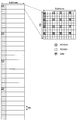
- PCFICH is used for notification of the number of OFDM symbols used for PDCCH (or the head symbol of PDSCH), and is mapped only to the head OFDM symbol of the subframe (see FIG. 5).
- PCFICH is arranged in the system band using 4REG (Resource Element Group).
- the radio base station notifies the user terminal of the number of OFDM symbols (CFI: Control Format Indicator) to which the PDCCH is allocated in each subframe as 2-bit information using the OFDM symbol at the head of the subframe.
- CFI Control Format Indicator
- the downlink control channel (PDCCH) is used for notification such as DL and UL scheduling, and is mapped to a resource to which PCFICH / PHICH is not allocated in the first 1 to 3 (or 1 to 4) symbols of the subframe ( (See FIG. 6).
- the radio base station transmits downlink control information arranged in the search space based on the search space set in the PDCCH for each user terminal.
- the PCFICH and PDCCH are mapped to the resource element (RE) according to a mapping rule that is uniquely determined as a function of the frequency bandwidth. That is, unless the communication bandwidth is changed, the control channel (for example, L1 / L2 control channel) mapping position cannot be changed.
- the present inventors when performing communication in a communication system in which a plurality of numerologies (communication parameters) are set in a plurality of user terminals, respectively, user terminals in which each numerology (communication parameter) is set.
- the information about the resource (partial resource) used for communication is notified to the user terminal, and the user terminal is designed to perform communication using predetermined communication parameters in the partial resource.
- the present inventors also provide information related to partial resources by using upper layer signaling, a physical control channel common to a plurality of numerologies (common control channel), or an individual physical control channel (unique control channel) for each numerology.
- the idea was to notify the user terminal using an individual control channel).
- a resource used for communication of a user terminal that uses a predetermined topology is referred to as a “partial resource”, but is not limited thereto.
- the partial resources corresponding to each neurology may be a resource in which at least one of frequency, time, code, and space is different among a plurality of pneumatics, or may be a resource in which all or some of them are different. Good.
- MBB, IoT, and URLLC will be described as examples of operation forms (service forms) that use pneumatics.
- the operation forms to which this embodiment is applicable are limited to this. Absent.
- each user terminal is set with a topology (communication parameter) for communication in the communication system, and the communication system has a configuration in which communication is performed with the same or different topology (communication parameter) for each user terminal. Can be taken.
- the several aspect demonstrated below may each be implemented independently, and can also be implemented in combination as appropriate.
- a 1st aspect demonstrates the case where the partial resource which a user terminal can use for communication using higher layer signaling is designated. Note that, when the user terminal is already connected to another cell (for example, an existing system), the higher layer signaling can be configured to be transmitted from the other cell to the user terminal. Moreover, although the following description shows the case where a frequency resource is set as a partial resource for each neurology, the present embodiment is not limited to this.
- the radio base station notifies the user terminal of information related to the partial resources that can be used for communication by the user terminal using higher layer signaling (RRC signaling, broadcast signal, etc.). For example, the radio base station designates the first partial resource to the user terminal that uses the first neurology (first communication parameter), and uses the second neurology (second communication parameter). The second partial resource is designated for the user terminal to be executed.
- the information regarding the partial resource may be configured to include at least one resource information among time, frequency, code, and space resource.
- the user terminal performs reception processing (demodulation, decoding, etc.) of the control channel (control signal) and the data channel (downlink data) within the range of the partial resource specified by higher layer signaling.
- the control channel transmitted using the partial resource can be an L1 / L2 control channel (at least one of PCFICH, PHICH, PDCCH, and EPDCCH).
- FIG. 7 shows an example of setting the first partial resource and the second partial resource in a predetermined frequency band.
- the frequency division (FDM) is performed.
- the first neurology (first partial resource) is set for IoT (or a user terminal that uses IoT)
- the second neurology (second partial resource) is for MBB. (Or a user terminal using MBB) is set.
- the user terminal in which the first partial resource is designated can use the IoT service by performing reception processing of the control channel and the data channel in the first partial resource.
- the user terminal to which the second partial resource is specified can use the MBB service by performing reception processing of the control channel and the data channel in the second partial resource.
- the first neurology (first partial resource) is set for URLLC (or a user terminal that uses URLLC), and the second topology (second partial resource) is for MBB. (Or a user terminal using MBB) is set.
- FIG. 7B shows a case where a discrete frequency is assigned to the second pneumatics (for example, MBB).
- the assignment may be controlled so that the resource index becomes a continuous index across the discrete frequency.
- resource indexes 0 to 15 are allocated to one of the second partial resources to which discrete frequencies are allocated.
- a resource index may be allocated independently for each discrete frequency. For example, resource indexes 0 to 15 are allocated to one area of the second partial resource to which the discrete frequency is allocated, and allocation is performed from the new index (here, index 71) to the other area of the second partial resource. be able to.
- a resource index designation field that is unchanged regardless of the setting of the partial resource. Scheduling can be performed with an L1 / L2 control signal including. As a result, the blind decoding process of the user terminal that receives the L1 / L2 control signal can be shared regardless of the location and size of the partial resource, and the circuit scale of the user terminal can be reduced.
- the partial resources may be set to be the same in the time interval in which the control channel (for example, the L1 / L2 control channel) is transmitted and received and in the time interval in which the data channel (DL data and / or UL data) is transmitted and received. It may be set differently. When setting differently, the respective partial resource information is notified to the user terminal by higher layer signaling.
- the control channel for example, the L1 / L2 control channel
- the data channel DL data and / or UL data
- the radio base station notifies the user terminal of at least a partial resource for the control channel (for example, L1 / L2 control channel) using higher layer signaling.
- the user terminal receives the L1 / L2 control channel with the whole or a part of the partial resources set by higher layer signaling.
- the user terminal can receive DL data and / or UL data based on the L1 / L2 control channel that performs scheduling of the DL data and UL data, instead of following the partial resources of higher layer signaling.
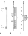
- the allocation area (partial resource) for the L1 / L2 control channel and the allocation area (partial resource) for the data channel can be set independently (see FIG. 8).
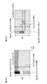
- FIG. 8 shows a case where a plurality of numerologies (services) are frequency division multiplexed (FDM) in a predetermined frequency band, and the control channel and data channel allocation resources for the same service are configured differently.
- FDM frequency division multiplexed
- FIG. 8A shows a case where the first neurology (first partial resource) is set for IoT, and the second neurology (second partial resource) is set for MBB.
- the user terminal receives the L1 / L2 control channel from the partial resources for the control channel specified by higher layer signaling, and controls transmission / reception of the data channel based on the L1 / L2 control channel.
- FIG. 8A shows a case where the data channel partial resource is set wider in the frequency direction than the control channel partial resource for IoT. In addition, a case is shown where the control channel partial resource is set wider in the frequency direction than the data channel partial resource for MBB.
- the first neurology (first partial resource) is set for URLLC
- the second neurology (second partial resource) is set for MBB
- the second pneumatic This shows a case where a discrete frequency is assigned to a logic (for example, MBB).
- the partial resource for the data channel is set wider in the frequency direction for the URLLC than the partial resource for the control channel for the URLLC
- the partial resource for the control channel is set for the partial resource for the data channel for the MBB.
- a case where the frequency is set wider in the frequency direction is shown.
- the partial resource for the control channel and the partial resource for the data channel can be assigned in different configurations, so that even when a plurality of neurology (services) are operated simultaneously, the assignment of each channel is possible. Can be controlled flexibly.
- a network notifies a user terminal of information on a partial resource that can be used in communication based on the neurology type and communication based on the neurology using higher layer signaling (broadcast information or RRC signaling).
- the radio base station transmits information on the first communication parameter (first neurology) and the first communication to the user terminal to which the first neurology (first communication parameter) is applied.
- Information about partial resources to be communicated using parameters is notified.
- the user terminal performs reception processing (for example, blind decoding) of the L1 / L2 control channel within the notified partial resource.
- the L1 / L2 control channel may be interleaved / distributed or spread over the entire resource region to which the L1 / L2 control channel can be mapped in the set partial resource.
- the user terminal When the user terminal detects scheduling information addressed to the user terminal (own terminal), the user terminal controls DL data reception and / or UL data transmission based on the scheduling information.
- Resources that can transmit / receive DL data / UL data may be limited to the set partial resources, or can be allocated outside the set partial resources within the range that can be specified by the L1 / L2 control channel. Also good.
- the user terminal when the user terminal is instructed to change the partial resource of the neurology type used by the user terminal for communication by higher layer signaling, the user terminal changes the partial resource used for communication in response to the change instruction request.
- the higher layer signaling may be included in the handover command.
- a partial resource that is different for each adjacent cell can be set as the neurology type, so that more flexible operation is possible.
- the upper layer signaling is used to notify the user terminal of the type of neurology type (predetermined communication parameters) and partial resources used for communication, thereby flexibly changing the resources used in each of the neurology. Can be changed. As a result, frequency utilization efficiency can be improved according to the communication environment and the like.
- a partial resource that can be used for communication by a user terminal is specified using a physical control channel (common control channel) common to a plurality of numerologies (partial resources or services). To do.
- a physical control channel common control channel
- numerologies partial resources or services
- the radio base station notifies information on partial resources that the user terminal can use for communication using the common control channel. For example, the radio base station designates the first partial resource to the user terminal that uses the first neurology (first communication parameter), and uses the second neurology (second communication parameter). The second partial resource is designated for the user terminal to be executed. In this case, the radio base station can designate a predetermined partial resource using the same common control channel for each user terminal.
- the user terminal receives the common control channel that performs demodulation and decoding regardless of the neurology set for itself, and based on the combination of the value of the common control channel and the set neurology. Determine the partial resources available for communication.
- the common control channel may have a configuration in which a predetermined number of subcarriers, a subcarrier interval, and a symbol length are applied regardless of the type of neurology set in the user terminal.
- the common control channel may be set using the same communication parameter as that of the existing system, or the common control channel may be set using a communication parameter corresponding to a predetermined neurology.
- the neurology type set in the user terminal may be set in the user terminal using higher layer signaling or may be set using the common control channel.
- the radio base station can transmit the common control channel to the user terminal every predetermined period (predetermined timing).
- predetermined timing a normal TTI (subframe), N times the normal TTI (N> 1), a TTI (or N times the TTI) to be applied in any of a plurality of pneumatics, or a radio frame is used. can do.
- FIG. 9A shows a case where a common control channel is transmitted for each normal TTI (subframe).
- the user terminal performs reception processing of a control channel (control signal) and a data channel (downlink data) for a predetermined neurology within a range of partial resources specified by the common control channel.
- the control channel transmitted using the partial resource can be an L1 / L2 control channel.
- FIG. 9B and FIG. 9C show the first partial resource (subband) set for the first neurology and the second partial resource set for the second neurology in the same time interval.
- the frequency division (FDM) is performed.
- a common control channel that specifies information about the first partial resource and the second partial resource is allocated.
- TDM time division multiplexed
- the first neurology (first partial resource) is set for IoT (or a user terminal that uses IoT), and the second topology (second partial resource) is for MBB. (Or a user terminal using MBB) is set.
- the common control channel designates partial resources (partial bands) of IoT and MBB to the user terminal.
- the user terminal for which the first partial resource is specified by the common control channel can use the IoT service by receiving the control channel and the data channel from the first partial resource. Further, the user terminal for which the second partial resource is specified by the common control channel can use the MBB service by receiving the control channel and the data channel from the second partial resource.
- the first neurology (first partial resource) is set for URLLC (or a user terminal using URLLC), and the second topology (second partial resource) is set to MBB. It shows a case of setting for use (or a user terminal using MBB).
- partial resources are frequency division multiplexed (FDM)
- discrete frequencies may be assigned to each service (each neurology).
- FIG. 9C shows a case where a discrete frequency is assigned to the second pneumatics (for example, MBB).
- the radio base station simultaneously designates the partial resource of the L1 / L2 control channel and the partial resource of the data channel (DL data and / or UL data) scheduled by the L1 / L2 control channel using the common control channel. (See FIGS. 9B and 9C). Alternatively, only the partial resource of the L1 / L2 control channel may be notified, and the data channel allocation resource (partial resource) may be designated using the L1 / L2 control channel.
- the user terminal first receives the common control channel and identifies partial resources that can be used for communication of the user terminal (own terminal). When the user terminal cannot receive the common control channel (or when decoding fails), the user terminal may perform control so as not to perform subsequent processing, for example, demodulation / decoding processing of the L1 / L2 control channel in the partial resource. Good. Note that the user terminal may receive information on the neurology type (communication parameter to be used) through the common control channel or may receive the information through higher layer signaling.
- the neurology type communication parameter to be used
- the user terminal After receiving the common control channel, the user terminal performs reception processing (for example, blind decoding) of the L1 / L2 control channel within the partial resource designated by the common control channel. Specifically, scheduling information (for example, DCI) for performing DL data reception or UL data transmission for each user within the partial resource is decoded.
- the L1 / L2 control channel (L1 / L2 control signal) may be interleaved, distributed, and spread over the entire resource area to which the L1 / L2 control signal can be mapped in the set partial resource. .
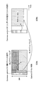
- the user terminal controls transmission / reception of DL data and / or UL data based on scheduling information included in the received L1 / L2 control channel (for example, DCI) (see FIG. 10).
- FIG. 10 shows a case where, in a certain subframe #n, a partial resource of the L1 / L2 control channel is designated by the common control channel, and the user terminal receives the L1 / L2 control channel by the designated partial resource. .
- the user terminal can receive DL data in the same subframe #n when the received L1 / L2 control channel indicates DL allocation. Further, when the received L1 / L2 control channel indicates transmission of UL data (UL grant), the user terminal transmits UL data in a subframe or TTI (here, subframe #m) after a predetermined timing. be able to.
- UL data for MBB partial resource information of UL data
- the common control channel may not be provided in the subframe #m.
- the common control channel can be configured to include information (data transmission type) indicating whether the data channel at a predetermined timing (for example, a predetermined TTI, a predetermined subframe, etc.) is UL transmission or DL transmission. That is, the radio base station can notify the user terminal whether the data channel at a predetermined timing is UL transmission or DL transmission using the common control channel.
- a predetermined timing for example, a predetermined TTI, a predetermined subframe, etc.
- the user terminal determines whether a predetermined timing (for example, the same subframe) is for DL data communication or UL data communication from the common control channel, and the partial resource area of each neurology (service) Can be determined.
- a predetermined timing for example, the same subframe
- UL data communication from the common control channel
- the user terminal controls UL transmission according to the instruction of the common control channel at the transmission timing of the UL data (for example, subframe #m). Also good. For example, even if UL data transmission is instructed in subframe #n, UL transmission in subframe #m is not performed unless UL data transmission is instructed (allowed) in the common control channel in subframe #m. It can be set as a structure (refer FIG. 11).
- the user terminal when the common control channel of subframe #m indicates UL transmission, the user terminal transmits UL data based on the scheduling information received in subframe #n. On the other hand, when the common control channel of subframe #m indicates DL transmission, the user terminal can perform control so as not to perform (drop) UL transmission.
- the user terminal performs control so that reception processing of other DL control channels and / or DL data is not performed at a predetermined timing (for example, subframe #m) in which UL data transmission is instructed on the common control channel. Also good. Thereby, the processing burden of the user terminal can be reduced.
- a partial resource that can be used for communication by a user terminal is specified by using a separate physical control channel (unique control channel) for each neurology (partial resource or service).
- unique control channel can be common within the same neurology.
- the radio base station notifies information related to the partial resources that can be used by the user terminal for communication using the unique control channel. For example, the radio base station gives the first partial resource to the user terminal using the first neurology (first communication parameter) using the unique control channel for the first neurology. specify.
- the second partial resource is specified for the user terminal that uses the second topology (second communication parameter) using the specific control channel for the second topology.
- the radio base station can notify the user terminal in advance of information related to resources to which a specific control channel is allocated (monitored by the user terminal). For example, the radio base station sets the resource information of the unique control channel for each neurology in the user terminal by higher layer signaling (for example, broadcast information, RRC signaling, etc.). At this time, the resource information of the specific control channel corresponding to each of the plurality of neurology may be notified to the user terminal, or the predetermined neurology (for example, the neurology used by each user terminal) may be notified. The resource information of the corresponding unique control channel may be selectively notified.
- higher layer signaling for example, broadcast information, RRC signaling, etc.
- the radio base station maps the unique control channel of each neurology (each service) to a partial resource (for example, a partial frequency) set by higher layer signaling. Further, the radio base station designates partial resources of the L1 / L2 control channel based on the unique control channel.
- the radio base station may specify the partial resource of the data channel with the unique control channel in addition to the partial resource of the L1 / L2 control channel. Alternatively, the data channel allocation area may be determined based on the L1 / L2 control channel. In this case, the radio base station can change the resource of the specific physical control channel semi-statically and dynamically change the L1 / L2 control channel and the data channel.
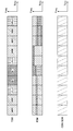
- 12A and 12B show the first partial resource (subband) set for the first pneumatics and the second partial resource set for the second pneumatics in the same time interval.
- the frequency division (FDM) is performed.
- a first unique control channel that designates the first partial resource and a second unique control channel that designates the second partial resource are allocated.
- FDM frequency-division multiplexing
- the first neurology (first partial resource) is set for IoT (or a user terminal that uses IoT), and the second topology (second partial resource) is for MBB. (Or a user terminal using MBB) is set.
- the first unique control information designates a partial resource for IoT (first partial resource) as a user terminal
- the second unique control information designates a partial resource for MBB (second partial resource) as a user terminal. Is specified. Note that FIG. 12A shows a case where the unique channel for URLLC to which no data channel is assigned is blank.
- the user terminal in which the first partial resource is specified by the first specific control channel can use the IoT service by receiving the control channel and the data channel from the first partial resource.
- the user terminal for which the second partial resource is specified by the second specific control channel can use the MBB service by receiving the control channel and the data channel from the second partial resource.
- the first neurology (first partial resource) is set for URLLC (or a user terminal that uses URLLC), and the second topology (second partial resource) is set to MBB. It shows a case of setting for use (or a user terminal using MBB).
- partial resources are frequency division multiplexed (FDM)
- discrete frequencies may be assigned to each service (each neurology).
- FIG. 12B shows a case where a specific channel for IoT to which no data channel is assigned is blank.
- the radio base station uses an eigencontrol channel, and a partial resource of an L1 / L2 control channel for each neurology and a partial resource of a data channel (DL data and / or UL data) scheduled by the L1 / L2 control channel Can be specified at the same time.
- a partial resource of an L1 / L2 control channel may be notified, and the data channel allocation resource (partial resource) may be designated using the L1 / L2 control channel.
- the specific control channel for designating the partial resource can be a control channel for designating the partial resource for each user group (for example, a user group to which the same neurology is applied).
- the unique control channel may have a different frame configuration (for example, different subcarrier interval, symbol length, TTI length) for each user group (see FIG. 13).
- the configuration (subcarrier interval, symbol length, TTI length, etc.) applied to each unique control channel can be the same as the control channel (for example, L1 / L2 control channel) or data channel that transmits scheduling information.
- a guard band may be provided between the unique control channels of each neurology (service) having different subcarrier intervals and symbol lengths.
- wireless communication system Wireless communication system
- the radio communication method according to each of the above aspects is applied.
- wireless communication method which concerns on each said aspect may be applied independently, respectively, and may be applied in combination.
- FIG. 14 is a diagram illustrating an example of a schematic configuration of a wireless communication system according to an embodiment of the present invention.
- carrier aggregation (CA) and / or dual connectivity (DC) in which a plurality of basic frequency blocks (component carriers) each having a system bandwidth (for example, 20 MHz) of the LTE system as one unit are applied.
- the wireless communication system 1 may be referred to as SUPER 3G, LTE-A (LTE-Advanced), IMT-Advanced, 4G, 5G, FRA (Future Radio Access), or the like.
- a radio communication system 1 shown in FIG. 14 includes a radio base station 11 that forms a macro cell C1, and radio base stations 12a to 12c that are arranged in the macro cell C1 and form a small cell C2 that is narrower than the macro cell C1. .
- the user terminal 20 is arrange
- the user terminal 20 can be connected to both the radio base station 11 and the radio base station 12. It is assumed that the user terminal 20 uses the macro cell C1 and the small cell C2 that use different frequencies simultaneously by CA or DC. In addition, the user terminal 20 can apply CA or DC using a plurality of cells (CC) (for example, six or more CCs). Further, the user terminal can use the license band CC and the unlicensed band CC as a plurality of cells. In addition, it can be set as the structure by which the TDD carrier which applies shortening TTI is contained in either of several cells.
- CC cells
- Communication between the user terminal 20 and the radio base station 11 can be performed using a carrier having a relatively low frequency band (for example, 2 GHz) and a narrow bandwidth (referred to as an existing carrier or a legacy carrier).
- a carrier having a relatively high frequency band for example, 3.5 GHz, 5 GHz, etc.
- the same carrier may be used.
- the configuration of the frequency band used by each radio base station is not limited to this.
- a wired connection for example, an optical fiber compliant with CPRI (Common Public Radio Interface), an X2 interface, etc.
- a wireless connection It can be set as the structure to do.
- the radio base station 11 and each radio base station 12 are connected to the higher station apparatus 30 and connected to the core network 40 via the higher station apparatus 30.
- the upper station device 30 includes, for example, an access gateway device, a radio network controller (RNC), a mobility management entity (MME), and the like, but is not limited thereto.
- RNC radio network controller
- MME mobility management entity
- Each radio base station 12 may be connected to the higher station apparatus 30 via the radio base station 11.
- the radio base station 11 is a radio base station having a relatively wide coverage, and may be called a macro base station, an aggregation node, an eNB (eNodeB), a transmission / reception point, or the like.
- the radio base station 12 is a radio base station having local coverage, and includes a small base station, a micro base station, a pico base station, a femto base station, a HeNB (Home eNodeB), an RRH (Remote Radio Head), and transmission / reception. It may be called a point.
- the radio base stations 11 and 12 are not distinguished, they are collectively referred to as a radio base station 10.
- Each user terminal 20 is a terminal compatible with various communication methods such as LTE and LTE-A, and may include not only a mobile communication terminal but also a fixed communication terminal.
- OFDMA orthogonal frequency division multiple access
- SC-FDMA single carrier-frequency division multiple access
- OFDMA is a multi-carrier transmission scheme that performs communication by dividing a frequency band into a plurality of narrow frequency bands (subcarriers) and mapping data to each subcarrier.
- SC-FDMA is a single-carrier transmission scheme that reduces interference between terminals by dividing the system bandwidth into bands consisting of one or continuous resource blocks for each terminal and using a plurality of terminals with mutually different bands. is there.
- the uplink and downlink radio access schemes are not limited to these combinations, and OFDMA may be used in the uplink.
- downlink channels include a downlink shared channel (PDSCH) shared by each user terminal 20, a broadcast channel (PBCH: Physical Broadcast Channel), a downlink L1 / L2 control channel, and the like. Used. User data, higher layer control information, SIB (System Information Block), etc. are transmitted by PDSCH. Also, MIB (Master Information Block) is transmitted by PBCH.
- PDSCH downlink shared channel
- PBCH Physical Broadcast Channel
- SIB System Information Block
- MIB Master Information Block
- Downlink L1 / L2 control channels include downlink control channels (PDCCH (Physical Downlink Control Channel), EPDCCH (Enhanced Physical Downlink Control Channel)), PCFICH (Physical Control Format Indicator Channel), PHICH (Physical Hybrid-ARQ Indicator Channel), etc. Including. Downlink control information (DCI: Downlink Control Information) including scheduling information of PDSCH and PUSCH is transmitted by PDCCH. The number of OFDM symbols used for PDCCH is transmitted by PCFICH. The HAICH transmission confirmation information (ACK / NACK) for PUSCH is transmitted by PHICH.
- EPDCCH is frequency-division multiplexed with PDSCH (downlink shared data channel), and is used for transmission of DCI and the like in the same manner as PDCCH.
- an uplink shared channel shared by each user terminal 20
- an uplink control channel PUCCH: Physical Uplink Control Channel
- PRACH Physical Random Access Channel
- User data and higher layer control information are transmitted by the PUSCH.
- Uplink control information including at least one of delivery confirmation information (ACK / NACK) and radio quality information (CQI) is transmitted by PUSCH or PUCCH.
- a random access preamble for establishing connection with a cell is transmitted by the PRACH.
- FIG. 15 is a diagram illustrating an example of the overall configuration of a radio base station according to an embodiment of the present invention.
- the radio base station 10 includes a plurality of transmission / reception antennas 101, an amplifier unit 102, a transmission / reception unit 103, a baseband signal processing unit 104, a call processing unit 105, and a transmission path interface 106.
- the transmission / reception unit 103 includes a transmission unit and a reception unit.
- User data transmitted from the radio base station 10 to the user terminal 20 via the downlink is input from the higher station apparatus 30 to the baseband signal processing unit 104 via the transmission path interface 106.
- PDCP Packet Data Convergence Protocol
- RLC Radio Link Control
- MAC Medium Access
- Retransmission control for example, HARQ (Hybrid Automatic Repeat reQuest) transmission processing
- HARQ Hybrid Automatic Repeat reQuest
- the downlink control signal is also subjected to transmission processing such as channel coding and inverse fast Fourier transform, and is transferred to the transmission / reception unit 103.
- the transmission / reception unit 103 converts the baseband signal output by precoding for each antenna from the baseband signal processing unit 104 to a radio frequency band and transmits the converted signal.
- the radio frequency signal frequency-converted by the transmission / reception unit 103 is amplified by the amplifier unit 102 and transmitted from the transmission / reception antenna 101.
- the transmission / reception unit (transmission unit) 103 transmits information on partial resources used by the user terminal for communication. For example, the transmission / reception unit (transmission unit) 103 notifies the user terminal of the information on the partial resource that can be used in the communication based on the new neurology type and the new neurology using higher layer signaling (broadcast information or RRC signaling). be able to. The higher layer signaling may be included in the handover command. Further, the transmission / reception unit (transmission unit) 103 may transmit the information on the partial resource through a common control channel common to a plurality of communication parameters or a unique control channel for each communication parameter.
- higher layer signaling may be included in the handover command.
- the transmission / reception unit (transmission unit) 103 may transmit the information on the partial resource through a common control channel common to a plurality of communication parameters or a unique control channel for each communication parameter.
- the transmission / reception unit 103 can be configured by a transmitter / receiver, a transmission / reception circuit, or a transmission / reception device which is described based on common recognition in the technical field according to the present invention.
- the transmission / reception part 103 may be comprised as an integral transmission / reception part, and may be comprised from a transmission part and a receiving part.
- the radio frequency signal received by the transmission / reception antenna 101 is amplified by the amplifier unit 102.
- the transmission / reception unit 103 receives the uplink signal amplified by the amplifier unit 102.
- the transmission / reception unit 103 converts the frequency of the received signal into a baseband signal and outputs it to the baseband signal processing unit 104.
- the baseband signal processing unit 104 performs fast Fourier transform (FFT) processing, inverse discrete Fourier transform (IDFT: Inverse Discrete Fourier Transform) processing, and error correction on user data included in the input upstream signal.
- FFT fast Fourier transform
- IDFT inverse discrete Fourier transform
- Decoding, MAC retransmission control reception processing, RLC layer and PDCP layer reception processing are performed and transferred to the upper station apparatus 30 via the transmission path interface 106.
- the call processing unit 105 performs call processing such as communication channel setting and release, state management of the radio base station 10, and radio resource management.
- the transmission path interface 106 transmits and receives signals to and from the higher station apparatus 30 via a predetermined interface.
- the transmission path interface 106 transmits and receives (backhaul signaling) signals to and from the adjacent radio base station 10 via an interface between base stations (for example, an optical fiber compliant with CPRI (Common Public Radio Interface), X2 interface). Also good.
- CPRI Common Public Radio Interface
- X2 interface also good.
- FIG. 16 is a diagram illustrating an example of a functional configuration of the radio base station according to the present embodiment. Note that FIG. 16 mainly shows functional blocks of characteristic portions in the present embodiment, and the wireless base station 10 also has other functional blocks necessary for wireless communication. As illustrated in FIG. 16, the baseband signal processing unit 104 includes a control unit (scheduler) 301, a transmission signal generation unit (generation unit) 302, a mapping unit 303, and a reception signal processing unit 304. .
- the baseband signal processing unit 104 includes a control unit (scheduler) 301, a transmission signal generation unit (generation unit) 302, a mapping unit 303, and a reception signal processing unit 304.
- the control unit (scheduler) 301 controls scheduling (for example, resource allocation) of downlink data signals transmitted on PDSCH and downlink control signals transmitted on PDCCH and / or EPDCCH. It also controls scheduling of system information, synchronization signals, paging information, CRS (Cell-specific Reference Signal), CSI-RS (Channel State Information Reference Signal), and the like. Further, scheduling of uplink reference signals, uplink data signals transmitted on PUSCH, uplink control signals transmitted on PUCCH and / or PUSCH, and the like is controlled.
- the control unit 301 can control transmission / reception of the transmission / reception unit (transmission unit) 103.
- the control unit 301 can control allocation of control channels and / or data channels to partial resources.
- the control unit 301 may be a controller, a control circuit, or a control device described based on common recognition in the technical field according to the present invention.
- the transmission signal generation unit 302 generates a DL signal (including a downlink data signal and a downlink control signal) based on an instruction from the control unit 301, and outputs the DL signal to the mapping unit 303.
- transmission signal generation section 302 generates a downlink data signal (PDSCH) including user data and outputs it to mapping section 303.
- the transmission signal generation unit 302 generates a downlink control signal (PDCCH / EPDCCH) including DCI (UL grant) and outputs the downlink control signal (PDCCH / EPDCCH) to the mapping unit 303.
- the transmission signal generation unit 302 generates downlink reference signals such as CRS and CSI-RS, and outputs them to the mapping unit 303.
- the mapping unit 303 maps the DL signal generated by the transmission signal generation unit 302 to a predetermined radio resource based on an instruction from the control unit 301, and outputs the DL signal to the transmission / reception unit 103.
- the mapping unit 303 can be a mapper, a mapping circuit, or a mapping device described based on common recognition in the technical field according to the present invention.
- the reception signal processing unit 304 performs reception processing (for example, demapping, demodulation, decoding, etc.) on the UL signal (HARQ-ACK, PUSCH, etc.) transmitted from the user terminal 20.
- the processing result is output to the control unit 301.
- the reception signal processing unit 304 may be configured by a signal processor, a signal processing circuit or a signal processing device, and a measuring device, a measurement circuit or a measuring device, which are described based on common recognition in the technical field according to the present invention. it can.
- FIG. 17 is a diagram illustrating an example of the overall configuration of a user terminal according to an embodiment of the present invention.
- the user terminal 20 includes a plurality of transmission / reception antennas 201 for MIMO transmission, an amplifier unit 202, a transmission / reception unit 203, a baseband signal processing unit 204, and an application unit 205.
- the transmission / reception unit 203 may include a transmission unit and a reception unit.
- the radio frequency signals received by the plurality of transmission / reception antennas 201 are each amplified by the amplifier unit 202.
- Each transmitting / receiving unit 203 receives the downlink signal amplified by the amplifier unit 202.
- the transmission / reception unit 203 converts the frequency of the received signal into a baseband signal and outputs it to the baseband signal processing unit 204.
- the transmission / reception unit (reception unit) 203 receives a DL signal (for example, an L1 / L2 control channel) transmitted from the radio base station. For example, the transmission / reception unit (reception unit) 203 transmits information on partial resources used for communication. In addition, the transmission / reception unit (reception unit) 203 can receive information on the type of neurology and the partial resources that can be used for communication by the neurology using higher layer signaling (broadcast information or RRC signaling). (See FIGS. 7 and 8).
- the transmission / reception unit (reception unit) 203 may receive information on partial resources on a common control channel common to a plurality of communication parameters or a unique control channel for each communication parameter (see FIGS. 9 and 12).
- the common control channel includes information on partial resources used for receiving the L1 / L2 control channel in predetermined communication parameters, or information on partial resources used for receiving the L1 / L2 control channel and the data channel (see FIG. 10).
- the common control channel may be configured to include information indicating whether communication at a predetermined timing is DL data communication or UL data communication (see FIG. 11). Also, different radio frame configurations may be applied to the unique control channel for each communication parameter (see FIG. 13).
- the transmission / reception unit 203 can be a transmitter / receiver, a transmission / reception circuit, or a transmission / reception device described based on common recognition in the technical field according to the present invention.
- the baseband signal processing unit 204 performs FFT processing, error correction decoding, retransmission control reception processing, and the like on the input baseband signal.
- the downlink user data is transferred to the application unit 205.
- the application unit 205 performs processing related to layers higher than the physical layer and the MAC layer.
- broadcast information in the downlink data is also transferred to the application unit 205.
- uplink user data is input from the application unit 205 to the baseband signal processing unit 204.
- the baseband signal processing unit 204 performs retransmission control transmission processing (for example, HARQ transmission processing), channel coding, precoding, discrete Fourier transform (DFT) processing, IFFT processing, and the like.
- the data is transferred to the transmission / reception unit 203.
- the transmission / reception unit 203 converts the baseband signal output from the baseband signal processing unit 204 into a radio frequency band and transmits it.
- the radio frequency signal frequency-converted by the transmission / reception unit 203 is amplified by the amplifier unit 202 and transmitted from the transmission / reception antenna 201.
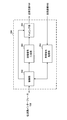
- FIG. 18 is a diagram illustrating an example of a functional configuration of the user terminal according to the present embodiment. Note that FIG. 18 mainly shows functional blocks of characteristic portions in the present embodiment, and the user terminal 20 also has other functional blocks necessary for wireless communication. As illustrated in FIG. 18, the baseband signal processing unit 204 included in the user terminal 20 includes a control unit 401, a transmission signal generation unit 402, a mapping unit 403, a reception signal processing unit 404, and a determination unit 405. I have.
- the control unit 401 obtains, from the received signal processing unit 404, a downlink control signal (a signal transmitted by PDCCH / EPDCCH) and a downlink data signal (a signal transmitted by PDSCH) transmitted from the radio base station 10.
- the control unit 401 generates an uplink control signal (for example, an acknowledgment signal (HARQ-ACK)) or an uplink data signal based on a downlink control signal, a result of determining whether retransmission control is necessary for the downlink data signal, or the like.
- HARQ-ACK acknowledgment signal
- the control unit 401 can control the transmission signal generation unit 402, the mapping unit 403, and the reception signal processing unit 404.
- the control unit 401 controls UL transmission and / or DL reception using predetermined communication parameters based on information on partial resources set by the radio base station. For example, the control unit 401 controls reception of the L1 / L2 control channel and the downlink data channel within a range of partial resources (see FIG. 7). Alternatively, the control unit 401 controls reception of the L1 / L2 control channel within the range of the partial resources, and controls reception of the downlink data channel based on the received L1 / L2 control channel (see FIG. 8).
- the control unit 401 may be a controller, a control circuit, or a control device described based on common recognition in the technical field according to the present invention.
- the transmission signal generation unit 402 generates a UL signal based on an instruction from the control unit 401 and outputs the UL signal to the mapping unit 403. For example, the transmission signal generation unit 402 generates an uplink control signal such as a delivery confirmation signal (HARQ-ACK) or channel state information (CSI) based on an instruction from the control unit 401.
- HARQ-ACK delivery confirmation signal
- CSI channel state information
- the transmission signal generation unit 402 generates an uplink data signal based on an instruction from the control unit 401. For example, the transmission signal generation unit 402 is instructed by the control unit 401 to generate an uplink data signal when the UL grant is included in the downlink control signal notified from the radio base station 10.
- the transmission signal generation unit 402 may be a signal generator, a signal generation circuit, or a signal generation device described based on common recognition in the technical field according to the present invention.
- the mapping unit 403 maps the uplink signal (uplink control signal and / or uplink data) generated by the transmission signal generation unit 402 to a radio resource based on an instruction from the control unit 401, and outputs the radio resource to the transmission / reception unit 203.
- the mapping unit 403 may be a mapper, a mapping circuit, or a mapping device described based on common recognition in the technical field according to the present invention.
- the reception signal processing unit 404 performs reception processing (for example, demapping, demodulation, decoding, etc.) on the DL signal (for example, downlink control signal transmitted from the radio base station, downlink data signal transmitted by PDSCH, etc.). I do.
- the reception signal processing unit 404 outputs information received from the radio base station 10 to the control unit 401 and the determination unit 405.
- the reception signal processing unit 404 outputs broadcast information, system information, RRC signaling, DCI, and the like to the control unit 401, for example.
- the reception signal processing unit 404 may be configured by a signal processor, a signal processing circuit or a signal processing device, and a measuring device, a measurement circuit or a measuring device which are described based on common recognition in the technical field according to the present invention. it can. Further, the reception signal processing unit 404 can constitute a reception unit according to the present invention.
- the determination unit 405 performs retransmission control determination (ACK / NACK) based on the decoding result of the received signal processing unit 404 and outputs the determination result to the control unit 401.
- ACK / NACK retransmission control determination
- ACK / NACK retransmission control determination
- the determination part 405 can be comprised from the determination circuit or determination apparatus demonstrated based on common recognition in the technical field which concerns on this invention.
- each functional block (components) are realized by any combination of hardware and / or software.
- the means for realizing each functional block is not particularly limited. That is, each functional block may be realized by one physically coupled device, or may be realized by two or more physically separated devices connected by wire or wirelessly and by a plurality of these devices. Good.
- a radio base station, a user terminal, etc. in an embodiment of the present invention may function as a computer that performs processing of the radio communication method of the present invention.
- FIG. 19 is a diagram illustrating an example of a hardware configuration of a radio base station and a user terminal according to an embodiment of the present invention.
- the wireless base station 10 and the user terminal 20 described above may be physically configured as a computer device including a processor 1001, a memory 1002, a storage 1003, a communication device 1004, an input device 1005, an output device 1006, a bus 1007, and the like. Good.
- the term “apparatus” can be read as a circuit, a device, a unit, or the like.
- the hardware configurations of the radio base station 10 and the user terminal 20 may be configured to include one or a plurality of each device illustrated in the figure, or may be configured not to include some devices.
- Each function in the radio base station 10 and the user terminal 20 is obtained by reading predetermined software (program) on hardware such as the processor 1001 and the memory 1002, so that the processor 1001 performs computation, and communication by the communication device 1004, This is realized by controlling reading and / or writing of data in the memory 1002 and the storage 1003.
- the processor 1001 controls the entire computer by operating an operating system, for example.
- the processor 1001 may be configured by a central processing unit (CPU) including an interface with peripheral devices, a control device, an arithmetic device, a register, and the like.
- CPU central processing unit
- the baseband signal processing unit 104 (204) and the call processing unit 105 described above may be realized by the processor 1001.
- the processor 1001 reads programs (program codes), software modules, and data from the storage 1003 and / or the communication device 1004 to the memory 1002, and executes various processes according to these.
- programs program codes
- software modules software modules
- data data from the storage 1003 and / or the communication device 1004 to the memory 1002, and executes various processes according to these.
- the program a program that causes a computer to execute at least a part of the operations described in the above embodiments is used.
- the control unit 401 of the user terminal 20 may be realized by a control program stored in the memory 1002 and operated by the processor 1001, and may be realized similarly for other functional blocks.
- the memory 1002 is a computer-readable recording medium, and may be configured by at least one of ROM (Read Only Memory), EPROM (Erasable Programmable ROM), RAM (Random Access Memory), and the like, for example.
- the memory 1002 may be called a register, a cache, a main memory (main storage device), or the like.
- the memory 1002 can store programs (program codes), software modules, and the like that can be executed to implement the wireless communication method according to an embodiment of the present invention.
- the storage 1003 is a computer-readable recording medium, and may be composed of at least one of an optical disk such as a CD-ROM (Compact Disc ROM), a hard disk drive, a flexible disk, a magneto-optical disk, and a flash memory, for example. .
- the storage 1003 may be referred to as an auxiliary storage device.
- the communication device 1004 is hardware (transmission / reception device) for performing communication between computers via a wired and / or wireless network, and is also referred to as a network device, a network controller, a network card, a communication module, or the like.
- a network device for example, the transmission / reception antenna 101 (201), the amplifier unit 102 (202), the transmission / reception unit 103 (203), the transmission path interface 106, and the like described above may be realized by the communication device 1004.
- the input device 1005 is an input device (for example, a keyboard, a mouse, etc.) that accepts external input.
- the output device 1006 is an output device (for example, a display, a speaker, etc.) that performs output to the outside.
- the input device 1005 and the output device 1006 may have an integrated configuration (for example, a touch panel).
- each device such as the processor 1001 and the memory 1002 is connected by a bus 1007 for communicating information.
- the bus 1007 may be configured with a single bus or may be configured with different buses between apparatuses.
- the radio base station 10 and the user terminal 20 include a microprocessor, a digital signal processor (DSP), an ASIC (Application Specific Integrated Circuit), a PLD (Programmable Logic Device), an FPGA (Field Programmable Gate Array), and the like. It may be configured including hardware, and a part or all of each functional block may be realized by the hardware. For example, the processor 1001 may be implemented by at least one of these hardware.
- DSP digital signal processor
- ASIC Application Specific Integrated Circuit
- PLD Programmable Logic Device
- FPGA Field Programmable Gate Array
- the channel and / or symbol may be a signal (signaling).
- the signal may be a message.
- a component carrier CC may be called a cell, a frequency carrier, a carrier frequency, or the like.
- the radio frame may be configured with one or a plurality of periods (frames) in the time domain.
- Each of the one or more periods (frames) constituting the radio frame may be referred to as a subframe.
- a subframe may be composed of one or more slots in the time domain.
- a slot may be composed of one or more symbols (OFDM symbols, SC-FDMA symbols, etc.) in the time domain.
- the radio frame, subframe, slot, and symbol all represent a time unit when transmitting a signal.
- Different names may be used for the radio frame, the subframe, the slot, and the symbol.
- one subframe may be referred to as a transmission time interval (TTI)
- a plurality of consecutive subframes may be referred to as a TTI
- one slot may be referred to as a TTI.
- the subframe or TTI may be a subframe (1 ms) in the existing LTE, a period shorter than 1 ms (for example, 1-13 symbols), or a period longer than 1 ms. Also good.
- TTI means, for example, a minimum time unit for scheduling in wireless communication.
- a radio base station performs scheduling to allocate radio resources (frequency bandwidth, transmission power, etc. that can be used in each user terminal) to each user terminal in units of TTI.
- the definition of TTI is not limited to this.
- a resource block is a resource allocation unit in the time domain and the frequency domain, and may include one or a plurality of continuous subcarriers (subcarriers) in the frequency domain. Further, the RB may include one or a plurality of symbols in the time domain, and may have a length of one slot, one subframe, or 1 TTI. One TTI and one subframe may each be composed of one or a plurality of resource blocks.
- the RB may be called a physical resource block (PRB: Physical RB), a PRB pair, an RB pair, or the like.
- the resource block may be composed of one or a plurality of resource elements (RE: Resource Element).
- RE Resource Element
- 1RE may be a radio resource region of 1 subcarrier and 1 symbol.
- the structure of the above-described radio frame, subframe, slot, symbol, and the like is merely an example.
- the configuration such as the cyclic prefix (CP) length can be variously changed.
- information, parameters, and the like described in this specification may be represented by absolute values, may be represented by relative values from a predetermined value, or may be represented by other corresponding information.
- the radio resource may be indicated by a predetermined index.
- software, instructions, information, etc. may be transmitted / received via a transmission medium.
- software may use websites, servers, or other devices using wired technology (coaxial cable, fiber optic cable, twisted pair and digital subscriber line (DSL), etc.) and / or wireless technology (infrared, microwave, etc.) When transmitted from a remote source, these wired and / or wireless technologies are included within the definition of transmission media.
- the radio base station in this specification may be read by the user terminal.
- each aspect / embodiment of the present invention may be applied to a configuration in which communication between a radio base station and a user terminal is replaced with communication between a plurality of user terminals (D2D: Device-to-Device).
- the user terminal 20 may have a function that the wireless base station 10 has.
- words such as “up” and “down” may be read as “side”.
- the uplink channel may be read as a side channel.
- a user terminal in this specification may be read by a radio base station.
- the wireless base station 10 may have a function that the user terminal 20 has.
- notification of predetermined information is not limited to explicitly performed, but is performed implicitly (for example, by not performing notification of the predetermined information). May be.
- notification of information is not limited to the aspect / embodiment described in this specification, and may be performed by other methods.
- notification of information includes physical layer signaling (eg, DCI (Downlink Control Information), UCI (Uplink Control Information)), upper layer signaling (eg, RRC (Radio Resource Control) signaling, broadcast information (MIB (Master Information Block)). ), SIB (System Information Block), etc.), MAC (Medium Access Control) signaling), other signals, or a combination thereof.
- the RRC signaling may be referred to as an RRC message, and may be, for example, an RRC connection setup (RRCConnectionSetup) message, an RRC connection reconfiguration (RRCConnectionReconfiguration) message, or the like.
- the MAC signaling may be notified by, for example, a MAC control element (MAC CE (Control Element)).
- MAC CE Control Element
- Each aspect / embodiment described herein includes LTE (Long Term Evolution), LTE-A (LTE-Advanced), LTE-B (LTE-Beyond), SUPER 3G, IMT-Advanced, 4G (4th generation mobile). communication system), 5G (5th generation mobile communication system), FRA (Future Radio Access), New-RAT (Radio Access Technology), CDMA2000, UMB (Ultra Mobile Broadband), IEEE 802.11 (Wi-Fi (registered trademark)) ), IEEE 802.16 (WiMAX (registered trademark)), IEEE 802.20, UWB (Ultra-WideBand), Bluetooth (registered trademark), other suitable wireless communication methods and / or based on them It may be applied to an extended next generation system.
Abstract
Description
(1)サブキャリア間隔、
(2)CP(Cyclic Prefix)長、
(3)シンボル長、
(4)TTIあたりのシンボル数、
(5)TTI長、
(6)フィルタリング処理やウィンドウイング処理。
第1の態様では、上位レイヤシグナリングを利用してユーザ端末が通信に用いることができる部分リソースを指定する場合について説明する。なお、上位レイヤシグナリングは、ユーザ端末が既に他のセル(例えば、既存システム)に接続している場合には、当該他のセルからユーザ端末に送信する構成とすることができる。また、以下の説明では、各ニューメロロジーに対して、周波数リソースを部分リソースとして設定する場合を示すが、本実施の形態はこれに限られない。
第1の態様を適用する場合のユーザ端末の動作方法の一例について説明する。
第2の態様では、複数のニューメロロジー(部分リソース又はサービス)に共通の物理制御チャネル(共通制御チャネル)を利用して、ユーザ端末が通信に用いることができる部分リソースを指定する場合について説明する。
ユーザ端末は、はじめに共通制御チャネルを受信し、当該ユーザ端末(自端末)の通信に用いることができる部分リソースを識別する。ユーザ端末は、当該共通制御チャネルが受信できない場合(又は、復号に失敗した場合)、それ以降の処理、例えば部分リソースにおけるL1/L2制御チャネルの復調・復号処理を行わないように制御してもよい。なお、ユーザ端末は、ニューメロロジー種別(利用する通信パラメータ)に関する情報を共通制御チャネルで受信してもよいし、上位レイヤシグナリングで受信してもよい。
共通制御チャネルは、所定タイミング(例えば、所定TTI、所定サブフレーム等)におけるデータチャネルがUL送信であるかDL送信であるかを示す情報(データ伝送種別)を含む構成とすることができる。つまり、無線基地局は、共通制御チャネルを用いて所定タイミングのデータチャネルがUL伝送であるかDL伝送であるかをユーザ端末に通知することができる。
第3の態様では、ニューメロロジー(部分リソース又はサービス)毎に個別の物理制御チャネル(固有制御チャネル)を利用して、ユーザ端末が通信に用いることができる部分リソースを指定する場合について説明する。なお、固有制御チャネルは、同じニューメロロジー内では共通とすることができる。
部分リソースを指定するための固有制御チャネルは、ユーザグループ(例えば、同じニューメロロジーを適用するユーザグループ)毎に部分リソースを指定する制御チャネルとすることができる。ユーザグループ毎に設定されるニューメロロジーが異なる場合、固有制御チャネルを、ユーザグループ毎に異なるフレーム構成(例えば、異なるサブキャリア間隔、シンボル長、TTI長)としてもよい(図13参照)。
以下、本発明の一実施形態に係る無線通信システムの構成について説明する。この無線通信システムでは、上記各態様に係る無線通信方法が適用される。なお、上記各態様に係る無線通信方法は、それぞれ単独で適用されてもよいし、組み合わせて適用されてもよい。
図15は、本発明の一実施形態に係る無線基地局の全体構成の一例を示す図である。無線基地局10は、複数の送受信アンテナ101と、アンプ部102と、送受信部103と、ベースバンド信号処理部104と、呼処理部105と、伝送路インターフェース106とを備えている。なお、送受信部103は、送信部及び受信部で構成される。
図17は、本発明の一実施形態に係るユーザ端末の全体構成の一例を示す図である。ユーザ端末20は、MIMO伝送のための複数の送受信アンテナ201と、アンプ部202と、送受信部203と、ベースバンド信号処理部204と、アプリケーション部205と、を備えている。なお、送受信部203は、送信部及び受信部から構成されてもよい。
なお、上記実施形態の説明に用いたブロック図は、機能単位のブロックを示している。これらの機能ブロック(構成部)は、ハードウェア及び/又はソフトウェアの任意の組み合わせによって実現される。また、各機能ブロックの実現手段は特に限定されない。すなわち、各機能ブロックは、物理的に結合した1つの装置により実現されてもよいし、物理的に分離した2つ以上の装置を有線又は無線で接続し、これら複数の装置により実現されてもよい。
Claims (10)
- 複数の通信パラメータが設定される通信システムで通信を行うユーザ端末であって、
通信に利用する部分リソースに関する情報を受信する受信部と、
前記部分リソースに関する情報に基づいて、所定の通信パラメータを利用してUL送信及び/又はDL受信を制御する制御部と、を有することを特徴とするユーザ端末。 - 前記受信部は、前記部分リソースに関する情報と通信パラメータに関する情報を上位レイヤシグナリングで受信し、前記制御部は、前記部分リソースの範囲でL1/L2制御チャネル及び下りデータチャネルの受信を制御することを特徴とする請求項1に記載のユーザ端末。
- 前記受信部は、L1/L2制御チャネルの部分リソースに関する情報を上位レイヤシグナリングで受信し、前記制御部は、前記部分リソースの範囲でL1/L2制御チャネルの受信を制御すると共に、受信したL1/L2制御チャネルに基づいて下りデータチャネルの受信を制御することを特徴とする請求項1に記載のユーザ端末。
- 前記受信部は、前記部分リソースに関する情報を複数の通信パラメータに共通の共通制御チャネルで受信することを特徴とする請求項1に記載のユーザ端末。
- 前記共通制御チャネルは、所定の通信パラメータにおいてL1/L2制御チャネルの受信に利用する部分リソースに関する情報、又はL1/L2制御チャネルとデータチャネルの受信に利用する部分リソースに関する情報を含むことを特徴とする請求項4に記載のユーザ端末。
- 前記共通制御チャネルは、所定タイミングにおける通信がDLデータ通信であるかULデータ通信であるかの情報を含むことを特徴とする請求項5に記載のユーザ端末。
- 前記受信部は、前記部分リソースに関する情報を通信パラメータ個別の固有制御チャネルで受信することを特徴とする請求項1に記載のユーザ端末。
- 前記固有制御チャネルは、通信パラメータ毎に異なる無線フレーム構成が適用されることを特徴とする請求項7に記載のユーザ端末。
- 複数の通信パラメータが設定される通信システムでユーザ端末と通信する無線基地局であって、
前記ユーザ端末が通信に利用する部分リソースに関する情報を送信する送信部と、
前記部分リソースに対して制御チャネル及び/又はデータチャネルの割当てを制御する制御部と、を有することを特徴とする無線基地局。 - 複数の通信パラメータが設定される通信システムで通信を行うユーザ端末の無線通信方法であって、
通信に利用する部分リソースに関する情報を受信する工程と、
前記部分リソースに関する情報に基づいて、所定の通信パラメータを利用してUL送信及び/又はDL受信を行う工程と、を有することを特徴とする無線通信方法。
Priority Applications (8)
| Application Number | Priority Date | Filing Date | Title |
|---|---|---|---|
| US16/073,167 US10820317B2 (en) | 2016-01-29 | 2017-01-26 | User terminal, radio base station and radio communication method |
| EP22201320.3A EP4187832A1 (en) | 2016-01-29 | 2017-01-26 | User terminal, radio base station and radio communication method |
| EP17744295.1A EP3399798A4 (en) | 2016-01-29 | 2017-01-26 | User terminal, wireless base station, and wireless communication method |
| CA3012310A CA3012310A1 (en) | 2016-01-29 | 2017-01-26 | User terminal, radio base station, and radio communication method |
| NZ744641A NZ744641A (en) | 2016-01-29 | 2017-01-26 | User terminal, radio base station and radio communication method |
| CN202210328853.2A CN114916041A (zh) | 2016-01-29 | 2017-01-26 | 终端、无线基站、无线通信系统及方法 |
| CN201780008858.4A CN108605267A (zh) | 2016-01-29 | 2017-01-26 | 用户终端、无线基站及无线通信方法 |
| JP2017563803A JP6791485B2 (ja) | 2016-01-29 | 2017-01-26 | 端末及び無線通信方法 |
Applications Claiming Priority (2)
| Application Number | Priority Date | Filing Date | Title |
|---|---|---|---|
| JP2016-016195 | 2016-01-29 | ||
| JP2016016195 | 2016-01-29 |
Publications (1)
| Publication Number | Publication Date |
|---|---|
| WO2017131065A1 true WO2017131065A1 (ja) | 2017-08-03 |
Family
ID=59398893
Family Applications (1)
| Application Number | Title | Priority Date | Filing Date |
|---|---|---|---|
| PCT/JP2017/002643 WO2017131065A1 (ja) | 2016-01-29 | 2017-01-26 | ユーザ端末、無線基地局及び無線通信方法 |
Country Status (7)
| Country | Link |
|---|---|
| US (1) | US10820317B2 (ja) |
| EP (2) | EP3399798A4 (ja) |
| JP (1) | JP6791485B2 (ja) |
| CN (2) | CN108605267A (ja) |
| CA (1) | CA3012310A1 (ja) |
| NZ (1) | NZ744641A (ja) |
| WO (1) | WO2017131065A1 (ja) |
Cited By (3)
| Publication number | Priority date | Publication date | Assignee | Title |
|---|---|---|---|---|
| WO2019198249A1 (ja) * | 2018-04-13 | 2019-10-17 | 株式会社Nttドコモ | ユーザ端末及び無線基地局 |
| CN111602347A (zh) * | 2017-11-20 | 2020-08-28 | 上海诺基亚贝尔股份有限公司 | 网络设备之间的回程传输 |
| JP2021501497A (ja) * | 2017-10-31 | 2021-01-14 | テレフオンアクチーボラゲット エルエム エリクソン(パブル) | サブキャリア間隔ヌメロロジの指示 |
Families Citing this family (11)
| Publication number | Priority date | Publication date | Assignee | Title |
|---|---|---|---|---|
| US10594465B2 (en) * | 2016-02-22 | 2020-03-17 | Huawei Technologies Co., Ltd. | System and method for flexible channelization |
| TW201735699A (zh) * | 2016-03-10 | 2017-10-01 | Idac控股公司 | 無線系統中訊號結構之確定 |
| EP4075704A1 (en) | 2016-05-11 | 2022-10-19 | IDAC Holdings, Inc. | Physical (phy) layer solutions to support use of mixed numerologies in the same channel |
| JP6594940B2 (ja) * | 2016-09-30 | 2019-10-23 | 華碩電腦股▲ふん▼有限公司 | 無線通信システムにおいて複数のヌメロロジの場合の制御チャネルを受信するための方法及び装置 |
| CA3044953C (en) | 2016-11-25 | 2021-11-02 | Lg Electronics Inc. | Method and apparatus for designing broadcast channel for nr in wireless communication system |
| EP3726908B1 (en) * | 2017-01-05 | 2022-04-06 | NEC Corporation | Radio access network node, radio terminal, and methods and non-transitory computer-readable media therefor |
| US10917278B2 (en) * | 2017-04-28 | 2021-02-09 | Nokia Technologies Oy | Frequency-domain transmitters and receivers which adapt to different subcarrier spacing configurations |
| US10575217B2 (en) | 2017-08-11 | 2020-02-25 | Qualcomm Incorporated | Techniques and apparatuses for managing sounding reference signal (SRS) transmissions in a bandwidth part |
| WO2020090096A1 (ja) * | 2018-11-01 | 2020-05-07 | 株式会社Nttドコモ | 基地局、ユーザ装置及び送信方法 |
| JP7201786B2 (ja) * | 2019-02-22 | 2023-01-10 | 株式会社Nttドコモ | 端末、基地局、通信方法及び無線通信システム |
| US20220210745A1 (en) * | 2019-05-15 | 2022-06-30 | Ntt Docomo, Inc. | User terminal and radio communication method |
Citations (2)
| Publication number | Priority date | Publication date | Assignee | Title |
|---|---|---|---|---|
| WO2011086655A1 (ja) * | 2010-01-12 | 2011-07-21 | 富士通株式会社 | 移動通信システム、無線通信装置、移動通信装置および無線通信方法 |
| US20160020891A1 (en) * | 2014-07-21 | 2016-01-21 | Intel IP Corporation | System and method for tdd communications |
Family Cites Families (34)
| Publication number | Priority date | Publication date | Assignee | Title |
|---|---|---|---|---|
| GB2439367A (en) * | 2006-06-20 | 2007-12-27 | Nec Corp | Separate ACK/NACK channel from a control channel |
| CN101127584A (zh) * | 2006-08-15 | 2008-02-20 | 华为技术有限公司 | 反馈及接收ack/nak信息的方法和装置 |
| CN101282319B (zh) * | 2007-04-05 | 2012-11-28 | 中兴通讯股份有限公司 | 一种基于ofdm技术的宽带无线通信系统带宽扩展方法 |
| CN102415132B (zh) * | 2009-04-21 | 2014-08-06 | 光学无线技术有限责任公司 | 终端装置和重发控制方法 |
| CN102239737B (zh) * | 2010-01-08 | 2015-09-30 | 华为技术有限公司 | 资源分配方法及装置 |
| KR101615985B1 (ko) * | 2010-05-24 | 2016-05-12 | 엘지전자 주식회사 | 불연속적 상향링크 자원 할당을 위한 방법 및 장치 |
| US9295045B2 (en) * | 2010-08-10 | 2016-03-22 | Panasonic Intellectual Property Corporation Of America | Base station, relay station, transmission method, and reception method |
| JP5285117B2 (ja) * | 2011-05-02 | 2013-09-11 | 株式会社エヌ・ティ・ティ・ドコモ | ユーザ端末、無線基地局装置、無線通信システム及び無線通信方法 |
| JP5898874B2 (ja) * | 2011-07-15 | 2016-04-06 | 株式会社Nttドコモ | ユーザ端末、無線基地局装置、無線通信システム及び無線通信方法 |
| KR101962245B1 (ko) * | 2011-09-23 | 2019-03-27 | 삼성전자 주식회사 | 광대역 단말과 협대역 단말을 함께 운용하는 무선통신시스템에서 협대역 단말의 시스템 접속 방법 및 장치 |
| JP5856810B2 (ja) * | 2011-11-02 | 2016-02-10 | シャープ株式会社 | 基地局装置、移動局装置、無線通信方法、無線通信システムおよび集積回路 |
| JP2013183299A (ja) * | 2012-03-02 | 2013-09-12 | Sharp Corp | 移動局装置、基地局装置、通信方法、集積回路および無線通信システム |
| JP6399728B2 (ja) * | 2012-03-15 | 2018-10-03 | シャープ株式会社 | 基地局装置、端末装置、通信方法および集積回路 |
| JP2013197783A (ja) * | 2012-03-19 | 2013-09-30 | Sharp Corp | 基地局、端末、通信方法および集積回路 |
| JP2013219507A (ja) * | 2012-04-06 | 2013-10-24 | Ntt Docomo Inc | 無線通信方法、ローカルエリア基地局装置、移動端末装置及び無線通信システム |
| WO2014000288A1 (zh) * | 2012-06-29 | 2014-01-03 | 华为技术有限公司 | 一种调度下行数据传输的方法和装置 |
| US9131498B2 (en) * | 2012-09-12 | 2015-09-08 | Futurewei Technologies, Inc. | System and method for adaptive transmission time interval (TTI) structure |
| CN104704877B (zh) * | 2012-10-26 | 2018-07-06 | 太阳专利信托公司 | 终端装置、基站装置、接收方法以及发送方法 |
| JP6301065B2 (ja) * | 2013-04-04 | 2018-03-28 | 株式会社Nttドコモ | 無線基地局、ユーザ端末および無線通信方法 |
| JP6468184B2 (ja) * | 2013-04-23 | 2019-02-13 | ソニー株式会社 | 通信制御装置、通信制御方法、無線通信システム及び端末装置 |
| JP5694493B2 (ja) * | 2013-12-09 | 2015-04-01 | 株式会社Nttドコモ | 無線通信システム、無線基地局、ユーザ端末及び無線通信制御方法 |
| US10200137B2 (en) * | 2013-12-27 | 2019-02-05 | Huawei Technologies Co., Ltd. | System and method for adaptive TTI coexistence with LTE |
| JP2015139106A (ja) * | 2014-01-22 | 2015-07-30 | 株式会社Nttドコモ | ユーザ端末、無線基地局及び無線通信方法 |
| US10862634B2 (en) * | 2014-03-07 | 2020-12-08 | Huawei Technologies Co., Ltd. | Systems and methods for OFDM with flexible sub-carrier spacing and symbol duration |
| JP5647749B1 (ja) | 2014-07-10 | 2015-01-07 | 翔天電子實業有限公司 | 按摩ヘッドユニット |
| WO2016004634A1 (en) * | 2014-07-11 | 2016-01-14 | Mediatek Singapore Pte. Ltd. | Method for enb, ue uplink transmission and reception |
| CN105282846B (zh) * | 2014-07-25 | 2019-06-11 | 中兴通讯股份有限公司 | 设备到设备通信方法及装置、设备到设备通信控制装置 |
| US10117256B2 (en) * | 2015-03-13 | 2018-10-30 | Federated Wireless, Inc. | System and method for spectrum sharing and interference management between wireless systems |
| GB2541213A (en) * | 2015-08-12 | 2017-02-15 | Nec Corp | Communication system |
| JP6105693B2 (ja) * | 2015-09-03 | 2017-03-29 | 株式会社Nttドコモ | 無線通信方法、無線通信システム及び無線基地局 |
| CN106937387A (zh) * | 2015-12-30 | 2017-07-07 | 华为技术有限公司 | 发送控制信号的方法和装置 |
| US10433283B2 (en) * | 2016-01-26 | 2019-10-01 | Huawei Technologies Co., Ltd. | System and method for bandwidth division and resource block allocation |
| KR20180013660A (ko) * | 2016-07-29 | 2018-02-07 | 삼성전자주식회사 | 이동 통신 시스템에서의 채널 상태 정보 보고 방법 및 장치 |
| US20190174531A1 (en) * | 2016-07-29 | 2019-06-06 | Ntt Docomo, Inc. | User terminal and radio communication method |
-
2017
- 2017-01-26 US US16/073,167 patent/US10820317B2/en active Active
- 2017-01-26 CN CN201780008858.4A patent/CN108605267A/zh active Pending
- 2017-01-26 EP EP17744295.1A patent/EP3399798A4/en not_active Withdrawn
- 2017-01-26 NZ NZ744641A patent/NZ744641A/en unknown
- 2017-01-26 EP EP22201320.3A patent/EP4187832A1/en active Pending
- 2017-01-26 CA CA3012310A patent/CA3012310A1/en active Pending
- 2017-01-26 WO PCT/JP2017/002643 patent/WO2017131065A1/ja active Application Filing
- 2017-01-26 JP JP2017563803A patent/JP6791485B2/ja active Active
- 2017-01-26 CN CN202210328853.2A patent/CN114916041A/zh active Pending
Patent Citations (2)
| Publication number | Priority date | Publication date | Assignee | Title |
|---|---|---|---|---|
| WO2011086655A1 (ja) * | 2010-01-12 | 2011-07-21 | 富士通株式会社 | 移動通信システム、無線通信装置、移動通信装置および無線通信方法 |
| US20160020891A1 (en) * | 2014-07-21 | 2016-01-21 | Intel IP Corporation | System and method for tdd communications |
Non-Patent Citations (1)
| Title |
|---|
| See also references of EP3399798A4 * |
Cited By (9)
| Publication number | Priority date | Publication date | Assignee | Title |
|---|---|---|---|---|
| JP2021501497A (ja) * | 2017-10-31 | 2021-01-14 | テレフオンアクチーボラゲット エルエム エリクソン(パブル) | サブキャリア間隔ヌメロロジの指示 |
| US11233689B2 (en) | 2017-10-31 | 2022-01-25 | Telefonaktiebolaget Lm Ericsson (Publ) | Indication of subcarrier spacing numerology |
| US11398940B2 (en) | 2017-10-31 | 2022-07-26 | Telefonaktiebolaget Lm Ericsson (Publ) | Indication of subcarrier spacing numerology |
| JP7299882B2 (ja) | 2017-10-31 | 2023-06-28 | テレフオンアクチーボラゲット エルエム エリクソン(パブル) | サブキャリア間隔ヌメロロジの指示 |
| US11736330B2 (en) | 2017-10-31 | 2023-08-22 | Telefonaktiebolaget Lm Ericsson (Publ) | Indication of subcarrier spacing numerology |
| CN111602347A (zh) * | 2017-11-20 | 2020-08-28 | 上海诺基亚贝尔股份有限公司 | 网络设备之间的回程传输 |
| EP3714555A4 (en) * | 2017-11-20 | 2021-07-07 | Nokia Solutions and Networks Oy | BACKHAUL TRANSFER BETWEEN NETWORK DEVICES |
| CN111602347B (zh) * | 2017-11-20 | 2022-06-07 | 上海诺基亚贝尔股份有限公司 | 网络设备之间的回程传输 |
| WO2019198249A1 (ja) * | 2018-04-13 | 2019-10-17 | 株式会社Nttドコモ | ユーザ端末及び無線基地局 |
Also Published As
| Publication number | Publication date |
|---|---|
| EP3399798A4 (en) | 2018-12-19 |
| EP3399798A1 (en) | 2018-11-07 |
| JP6791485B2 (ja) | 2020-11-25 |
| US20190045506A1 (en) | 2019-02-07 |
| CN108605267A (zh) | 2018-09-28 |
| JPWO2017131065A1 (ja) | 2018-11-22 |
| EP4187832A1 (en) | 2023-05-31 |
| CA3012310A1 (en) | 2017-08-03 |
| CN114916041A (zh) | 2022-08-16 |
| US10820317B2 (en) | 2020-10-27 |
| NZ744641A (en) | 2023-11-24 |
Similar Documents
| Publication | Publication Date | Title |
|---|---|---|
| JP7197660B2 (ja) | 端末、無線通信方法、基地局及びシステム | |
| JP6791485B2 (ja) | 端末及び無線通信方法 | |
| WO2018084137A1 (ja) | ユーザ端末及び無線通信方法 | |
| WO2017038894A1 (ja) | ユーザ端末、無線基地局及び無線通信方法 | |
| WO2017078128A1 (ja) | ユーザ端末、無線基地局及び無線通信方法 | |
| WO2017164222A1 (ja) | ユーザ端末、無線基地局及び無線通信方法 | |
| WO2017110956A1 (ja) | ユーザ端末、無線基地局及び無線通信方法 | |
| WO2017130991A1 (ja) | ユーザ端末、無線基地局及び無線通信方法 | |
| WO2017164147A1 (ja) | ユーザ端末、無線基地局及び無線通信方法 | |
| JP7418507B2 (ja) | 端末、無線通信方法、基地局及びシステム | |
| JP7054405B2 (ja) | 端末、無線通信方法、基地局及びシステム | |
| JPWO2017110960A1 (ja) | ユーザ端末及び無線通信方法 | |
| WO2017038532A1 (ja) | ユーザ端末、無線基地局及び無線通信方法 | |
| JPWO2017150451A1 (ja) | ユーザ端末、無線基地局及び無線通信方法 | |
| WO2017142031A1 (ja) | ユーザ端末、無線基地局及び無線通信方法 | |
| WO2018128183A1 (ja) | ユーザ端末及び無線通信方法 | |
| WO2017038531A1 (ja) | ユーザ端末、無線基地局及び無線通信方法 | |
| WO2017150448A1 (ja) | ユーザ端末、無線基地局及び無線通信方法 | |
| JP7010696B2 (ja) | 端末及び無線通信方法 | |
| JP7227000B2 (ja) | 端末、基地局、無線通信方法及びシステム |
Legal Events
| Date | Code | Title | Description |
|---|---|---|---|
| 121 | Ep: the epo has been informed by wipo that ep was designated in this application |
Ref document number: 17744295 Country of ref document: EP Kind code of ref document: A1 |
|
| WWE | Wipo information: entry into national phase |
Ref document number: 3012310 Country of ref document: CA |
|
| WWE | Wipo information: entry into national phase |
Ref document number: 2017563803 Country of ref document: JP |
|
| NENP | Non-entry into the national phase |
Ref country code: DE |
|
| WWE | Wipo information: entry into national phase |
Ref document number: 2017744295 Country of ref document: EP |
|
| ENP | Entry into the national phase |
Ref document number: 2017744295 Country of ref document: EP Effective date: 20180801 |