WO2017131016A1 - 電極、電極を用いたキャパシタ、および電極の製造方法 - Google Patents
電極、電極を用いたキャパシタ、および電極の製造方法 Download PDFInfo
- Publication number
- WO2017131016A1 WO2017131016A1 PCT/JP2017/002507 JP2017002507W WO2017131016A1 WO 2017131016 A1 WO2017131016 A1 WO 2017131016A1 JP 2017002507 W JP2017002507 W JP 2017002507W WO 2017131016 A1 WO2017131016 A1 WO 2017131016A1
- Authority
- WO
- WIPO (PCT)
- Prior art keywords
- electrode
- carbon
- fibrous
- fibrous cellulose
- carbon powder
- Prior art date
- Legal status (The legal status is an assumption and is not a legal conclusion. Google has not performed a legal analysis and makes no representation as to the accuracy of the status listed.)
- Ceased
Links
Images



Classifications
-
- H—ELECTRICITY
- H01—ELECTRIC ELEMENTS
- H01G—CAPACITORS; CAPACITORS, RECTIFIERS, DETECTORS, SWITCHING DEVICES, LIGHT-SENSITIVE OR TEMPERATURE-SENSITIVE DEVICES OF THE ELECTROLYTIC TYPE
- H01G11/00—Hybrid capacitors, i.e. capacitors having different positive and negative electrodes; Electric double-layer [EDL] capacitors; Processes for the manufacture thereof or of parts thereof
- H01G11/22—Electrodes
- H01G11/30—Electrodes characterised by their material
- H01G11/32—Carbon-based
- H01G11/38—Carbon pastes or blends; Binders or additives therein
-
- H—ELECTRICITY
- H01—ELECTRIC ELEMENTS
- H01G—CAPACITORS; CAPACITORS, RECTIFIERS, DETECTORS, SWITCHING DEVICES, LIGHT-SENSITIVE OR TEMPERATURE-SENSITIVE DEVICES OF THE ELECTROLYTIC TYPE
- H01G11/00—Hybrid capacitors, i.e. capacitors having different positive and negative electrodes; Electric double-layer [EDL] capacitors; Processes for the manufacture thereof or of parts thereof
- H01G11/22—Electrodes
- H01G11/30—Electrodes characterised by their material
- H01G11/32—Carbon-based
- H01G11/40—Fibres
-
- H—ELECTRICITY
- H01—ELECTRIC ELEMENTS
- H01G—CAPACITORS; CAPACITORS, RECTIFIERS, DETECTORS, SWITCHING DEVICES, LIGHT-SENSITIVE OR TEMPERATURE-SENSITIVE DEVICES OF THE ELECTROLYTIC TYPE
- H01G11/00—Hybrid capacitors, i.e. capacitors having different positive and negative electrodes; Electric double-layer [EDL] capacitors; Processes for the manufacture thereof or of parts thereof
- H01G11/22—Electrodes
- H01G11/30—Electrodes characterised by their material
- H01G11/32—Carbon-based
- H01G11/42—Powders or particles, e.g. composition thereof
-
- H—ELECTRICITY
- H01—ELECTRIC ELEMENTS
- H01G—CAPACITORS; CAPACITORS, RECTIFIERS, DETECTORS, SWITCHING DEVICES, LIGHT-SENSITIVE OR TEMPERATURE-SENSITIVE DEVICES OF THE ELECTROLYTIC TYPE
- H01G11/00—Hybrid capacitors, i.e. capacitors having different positive and negative electrodes; Electric double-layer [EDL] capacitors; Processes for the manufacture thereof or of parts thereof
- H01G11/84—Processes for the manufacture of hybrid or EDL capacitors, or components thereof
- H01G11/86—Processes for the manufacture of hybrid or EDL capacitors, or components thereof specially adapted for electrodes
Definitions
- the present invention relates to an electrode, a capacitor using the electrode, and a method for manufacturing the electrode.
- a capacitor is composed of a pair of electrodes, a separator existing between the electrodes, and a current collecting layer of each electrode.
- Carbon materials such as carbon powder are used for typical electrodes used in capacitors.
- the following methods are known as methods for producing electrodes used for capacitors. That is, after adding and mixing a conductive material such as acetylene black and a resin such as polytetrafluoroethylene and tetrafluoroethylene resin to activated carbon powder, which is a representative electrode material, press molding. A sheet-like polarizable electrode is formed. In addition to this, there is a method (coating method) in which the mixture is contained in a solvent and applied to a current collector.
- the resin electrode is used in the capacitor electrode, but there is a problem that the internal resistance of the electrode is increased by the resin.
- the internal resistance can be reduced by using fibrous carbon having conductivity instead of the resin binder as the binder, it is required to further reduce the internal resistance and increase the capacity density.
- the present invention has been proposed to solve the above problems.
- the object is to provide an electrode having an increased capacitance density by reducing internal resistance, a capacitor using the electrode, and a method for manufacturing the electrode.
- the electrode of the present invention includes carbon powder, cellulose, and fibrous carbon, and the carbon powder is supported between the fibrous cellulose and the fibrous carbon fibers.
- the ratio of the cellulose to the total weight of the cellulose and fibrous carbon may be 5% by weight to 75% by weight.
- the ratio of the fibrous cellulose to the total weight of the carbon powder, the fibrous cellulose, and the fibrous carbon may be 2% by weight or more.
- the fibrous carbon may have an outer diameter of 1 to 100 nm and a length of 50 to 1000 ⁇ m, and the fibrous cellulose may have an outer diameter of 4 to 100 nm and a length of 50 to 1000 ⁇ m.
- the carbon powder may be porous carbon black.
- a capacitor in which the electrode described above is formed on a current collector is also an embodiment of the present invention.
- the current collector may be preliminarily roughened by etching or the like, the electrode may be formed into a sheet shape, and the electrode and the current collector may be press bonded.
- the method for producing the electrode is also an embodiment of the present invention, in which a dispersion step of dispersing carbon powder, fibrous cellulose, and fibrous carbon in a solvent, and a solvent of the solution obtained in the dispersion step And an electrode forming step of obtaining an electrode containing carbon powder, fibrous cellulose, and fibrous carbon.
- the solvent is removed by filtering the solution obtained in the dispersion step using a filtration member, thereby forming a sheet-like electrode containing carbon powder, fibrous cellulose, and fibrous carbon. You may do it.
- the solution obtained in the dispersing step is applied on a current collector and removed by evaporating the solvent, and carbon powder, fibrous cellulose, and fibrous carbon are removed on the current collector. May be formed.
- an electrode with reduced internal resistance it is possible to provide an electrode with reduced internal resistance, a capacitor using the electrode, and a method for manufacturing the electrode.
- FIG. 1 It is sectional drawing which shows an example of a structure of the coin-shaped electric double layer capacitor of 1st Embodiment.
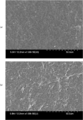
- A is an SEM ( ⁇ 1.00 k) image of a sheet electrode prepared from a solution in which carbon powder, fibrous cellulose and carbon nanotubes are dispersed, and
- (b) is a solution in which carbon powder and carbon nanotubes are dispersed.
- It is a SEM (x1.00k) image of the sheet electrode produced from the inside.
- It is the graph showing the relationship between the direct current internal resistance and the ratio of a fibrous cellulose in the electric double layer capacitor of an Example.
- Electrode and an electrode manufacturing method according to the present invention will be described in detail.
- a capacitor to which the electrode of this embodiment is applied will be described taking a coin-shaped electric double layer capacitor as an example.
- the electrode and the electrode manufacturing method according to the present invention are applicable not only to electric double layer capacitors.
- it can be applied to power storage devices such as various capacitors and secondary batteries such as electrochemical capacitors including lithium ion capacitors.
- the electrode and the electrode manufacturing method according to the present invention are not limited to the coin-type electric double layer capacitor, but may be applied to a laminate type heat sealed using a laminate film. Moreover, you may apply to the cylindrical element wound through the separator between the positive electrode and the negative electrode. Furthermore, the present invention can also be applied to power storage devices such as various capacitors and secondary batteries using a stacked element that is stacked between a positive electrode and a negative electrode via a separator.
- FIG. 1 is a cross-sectional view of a coin type electric double layer capacitor in which a sheet electrode is applied to a coin type cell as an example of an electric double layer capacitor.
- the coin-shaped electric double layer capacitor includes a negative electrode case 1, an electrolytic solution 2, an electrode 3, a separator 4, an electrode 5, a positive electrode case 6, and a gasket 7.
- the negative electrode case 1 and the positive electrode case 6 are cell casings that overlap to form a space inside.
- the negative electrode case 1 serves as a negative electrode current collector and a negative electrode terminal.
- the positive electrode case 6 serves as a positive electrode current collector and a positive electrode terminal.
- the gasket 7 is interposed in the caulking between the negative electrode case 1 and the positive electrode case 6. The gasket 7 maintains electrical insulation between the negative electrode and the positive electrode, and seals and seals the cell contents.
- Electrolytic solution 2, electrode 3, electrode 5, and separator 4 are cell contents and are accommodated in a space formed by negative electrode case 1 and positive electrode case 6.
- the electrodes 3 and 5 are integrated with a current collector (not shown).
- the electrode 3 is fixed and electrically connected to the positive electrode case 6 by a conductive resin adhesive, press bonding, or the like.
- the electrode 5 is fixed and electrically connected to the negative electrode case 1 by a conductive resin adhesive, press bonding, or the like.
- the separator 4 is disposed so as to be interposed between the electrode 3 and the electrode 5 in order to prevent a short circuit due to contact between the opposing electrode 3 and the electrode 5.
- the electrolytic solution 2 is impregnated in the electrode 3, the electrode 5, and the separator 7.
- the electrode 3 and the electrode 5 are sheet-like electrodes containing carbon powder, fibrous cellulose, and fibrous carbon.
- the sheet-like electrode can be obtained by mixing and dispersing carbon powder, fibrous cellulose, and fibrous carbon in a solvent, and then removing the solvent.
- Carbon powder expresses the main capacity of the electrode.
- the types of carbon powder include natural plant tissues such as palm, synthetic resins such as phenol, activated carbon derived from fossil fuels such as coal, coke, and pitch, ketjen black, acetylene black, channel black, etc. And carbon black, carbon nanohorn, amorphous carbon, natural graphite, artificial graphite, graphitized ketjen black, activated carbon, mesoporous carbon, and the like.
- the carbon powder is preferably used after being subjected to a porous treatment such as activation treatment or opening treatment.
- the carbon powder activation method varies depending on the raw material used, but conventionally known activation treatments such as a gas activation method and a drug activation method can be usually used.
- the gas used in the gas activation method include water vapor, air, carbon monoxide, carbon dioxide, hydrogen chloride, oxygen, or a gas composed of a mixture thereof.
- the chemicals used in the chemical activation method include alkali metal hydroxides such as sodium hydroxide and potassium hydroxide, alkaline earth metal hydroxides such as calcium hydroxide, boric acid, phosphoric acid, sulfuric acid, and hydrochloric acid.
- Inorganic acids such as zinc chloride or inorganic salts such as zinc chloride.
- the carbon powder is heat-treated as necessary.
- an opening treatment for forming holes in the carbon powder may be used.
- the carbon powder preferably has a specific surface area in the range of 600 to 2000 m 2 / g.
- the carbon powder preferably has an average primary particle size of less than 100 nm, and particularly preferably less than 50 nm. If the average particle size of the carbon powder is less than 100 nm, the diffusion resistance is low and the conductivity is high because of the extremely small particle size. Moreover, since the specific surface area by the porous treatment is large, an effect of expressing a high capacity can be expected. If the average particle diameter of the carbon powder is larger than 100 nm, the ion diffusion resistance in the carbon powder particles increases, and the internal resistance of the resulting capacitor increases.
- the average particle diameter of the carbon powder is larger than 100 nm, there is a possibility that it is difficult to be supported between fibers of fibrous carbon or fibrous cellulose.
- the carbon powder is too fine, the carbon powder may be agglomerated and supported between the fibers, so the average particle diameter is preferably 5 nm or more.
- the improvement of electrical conductivity is obtained by taking the form which connected the very small carbon powder which made the average particle diameter less than 100 nm individually in a daisy chain form.
- the material of the carbon powder is not limited to a specific material, but carbon black is particularly preferable. Moreover, even when the average particle diameter of the carbon powder is less than 10 ⁇ m, the effects of the present invention can be achieved by the ultracentrifugation process and the jet mixing process described later as the dispersion method.
- fibrous carbon The fibrous carbon used in the present embodiment plays a role of a binder in papermaking molding. That is, the carbon powder is dispersed and supported between the fibrous carbon fibers. Moreover, since fibrous carbon has electroconductivity, it does not have the bad influence which increases the internal resistance of an electrode like a resin-type binder. Examples of the type of fibrous carbon include fibrous carbon such as carbon nanotubes (hereinafter referred to as CNT) and carbon nanofibers (hereinafter referred to as CNF). In addition, you may use the opening process and activation process which make a hole in the front-end
- CNT carbon nanotubes
- CNF carbon nanofibers
- the CNT used as the fibrous carbon may be a single-walled carbon nanotube (SWCNT) having a single graphene sheet or a multi-walled carbon nanotube (MWCNT) in which two or more graphene sheets are rounded coaxially and the tube wall forms a multilayer. Well, they may be mixed. Moreover, since the capacity density of CNT itself is so high that there are few layers of the graphene sheet of CNT, CNT of the number of layers is 50 layers or less, Preferably the range of 10 layers or less is preferable from the point of capacity density.
- the outer diameter of the fibrous carbon is desirably 1 to 100 nm, preferably 2 to 70 nm, and more preferably 3 to 40 nm.
- the length of the fibrous carbon is preferably 50 to 1000 ⁇ m, preferably 70 to 500 ⁇ m, more preferably 100 to 200 ⁇ m.
- the specific surface area of the fibrous carbon is 100 to 2600 m 2 / g, preferably 200 to 2000 m 2 / g. If the specific surface area is larger than 2600 m 2 / g, the formed sheet electrode tends to expand, and if it is smaller than 100 m 2 / g, the electrode density is difficult to increase.
- Fibrous cellulose can be obtained, for example, from trees such as bamboo, broad-leaved trees, conifers, rice straw, sugarcane pomace, sugar beet pomace, cassava pomace or potato pomace. Fibrous cellulose is obtained by defibrating cellulose. Fibrous cellulose, together with fibrous carbon, plays the role of a binder when forming a sheet-like electrode. Examples of fibrous cellulose include cellulose nanofibers. The cellulose nanofiber is preferably a fibrous cellulose having an outer diameter of 4 to 100 nm and a length of 50 to 1000 ⁇ m.
- the fibrous cellulose and the fibrous carbon are uniformly dispersed when mixed in a solvent. Further, it is considered that the carbon powder is prevented from agglomerating and is uniformly entangled between the dispersed fibers.
- particle diameter and outer diameter of carbon powder and fibrous carbon were measured by ASTM D3849-04 (also referred to as ASTM particle diameter).
- Electrodes 3 and 5 of this embodiment contain the above carbon powder, fibrous cellulose, and a mixture of fibrous carbon. It is preferable that the carbon powder is 70 wt% or more and 95 wt% or less with respect to the total amount of the mixture, and the remainder is fibrous cellulose and fibrous carbon. If the carbon powder is less than 70% by weight, sufficient electrical characteristics as an electrode cannot be obtained. If it exceeds 95% by weight, the amount of the binder is reduced as a result, and it may not be possible to form a sheet.
- the amount of fibrous cellulose is preferably 5% by weight or more and 75% by weight or less with respect to the total amount of fibrous cellulose and fibrous carbon.
- the fibrous cellulose is less than 5% by weight, the carbon terminal and the fibrous carbon tend to aggregate, and the internal resistance of the capacitor increases and the capacity density tends to decrease. Up to at least 75% by weight, there was no particular effect on the insulating properties of the fibrous cellulose, and neither an increase in the internal resistance of the capacitor nor a decrease in the capacitance density was confirmed.
- the ratio of the fibrous cellulose to the total amount of the mixture constituting the electrodes 3 and 5 is preferably 2% by weight or more.
- the fibrous cellulose is preferably 20% by weight or more with respect to the total amount of fibrous cellulose and fibrous carbon.
- the ratio of the fibrous cellulose is at least 1% by weight or less with respect to the total amount of the mixture constituting the electrodes 3 and 5, the mixture formed into a sheet shape is press-bonded to the etched current collector.
- the anchor effect does not work well, and the mixture molded into a sheet is peeled off from the current collector, increasing the internal resistance.
- the ratio of fibrous cellulose is 2% by weight or more with respect to the total amount of the mixture constituting the electrode, the anchor effect works well, and the electrode and the current collector can be integrated by press bonding. Adhesive is not required. If the conductive adhesive is not required, the internal resistance will not be increased by the resin binder which is an adhesive component contained in the conductive adhesive.
- Solvents for mixing and dispersing carbon powder, fibrous cellulose and fibrous carbon include methanol, alcohols such as ethanol and 2-propanol, hydrocarbon solvents, aromatic solvents, N-methyl-2-pyrrolidone (NMP). ) And N, N-dimethylformamide (DMF), water, and various solvents such as water, those using these solvents alone, or those containing a mixture of two or more. Moreover, you may add additives, such as a dispersing agent, in this solvent.
- a conductive material such as aluminum foil, platinum, gold, nickel, titanium, steel, and carbon can be used.
- shape of the current collector any shape such as a film shape, a foil shape, a plate shape, a net shape, an expanded metal shape, and a cylindrical shape can be adopted.
- the surface of the current collector may be formed with an uneven surface (roughened) by etching or the like, or may be a plain surface.
- Negative electrode case positive electrode case
- the negative electrode case 1 is formed by drawing a stainless steel plate whose outer surface is plated with Ni. Further, the positive electrode case 6 is made of stainless steel plated with Ni on the outer side surface serving as the cell case main body or a valve action metal such as Al or Ti.
- Mo-containing stainless steels such as SUS316, 316L and double-layered stainless steel, and valve metals such as Al and Ti have high corrosion resistance and can be suitably used. Further, it is particularly preferable to use a clad material in which stainless steel and a valve metal such as Ai or Ti are bonded by crimping by cold rolling or the like, with the valve metal side being the inner surface of the cell. This is because a cell having high corrosion resistance against high voltage application, high mechanical strength at the time of sealing, and high reliability of sealing can be obtained.
- the negative electrode case 1 and the positive electrode case 6 may be made of the materials described as the above-described current collector, or may be applied in the form.
- the separator 4 can be a cellulose separator, a synthetic fiber nonwoven fabric separator, a mixed paper separator made by mixing cellulose and synthetic fibers, or the like.
- Polyester, polyphenylene sulfide, polyethylene terephthalate, polybutylene terephthalate, polyamide, polyimide, fluororesin, polyolefin resins such as polypropylene and polyethylene, non-woven fabrics made of fibers such as ceramics and glass, mixed paper or porous films are preferably used. Can do. When performing reflow soldering, a resin having a heat distortion temperature of 230 ° C. or higher is used.
- polyphenylene sulfide polyethylene terephthalate, polyamide, fluororesin, ceramics, glass, or the like can be used.
- an acid-resistant material synthetic fiber nonwoven fabric or glass material.
- Electrolytic Solution 2 The solvent of the electrolytic solution 2 is ethylene carbonate, propylene carbonate, vinylene carbonate, butylene carbonate, 4-fluoro-1,3-dioxolan-2-one, 4- (trifluoromethyl) -1,3- Cyclic carbonates such as dioxolan-2-one, dimethyl carbonate, ethyl methyl carbonate, diethyl carbonate, methyl n-propyl carbonate, methyl isopropyl carbonate, n-butyl methyl carbonate, diethyl carbonate, ethyl n-propyl carbonate, ethyl isopropyl carbonate, n -Butylethyl carbonate, di-n-propyl carbonate, diisopropyl carbonate, di-n-butyl carbonate, fluoroethyl methyl carbonate, difluoroethyl methyl Carbonate, chain carbonate such as trifluoroethyl methyl carbon
- the sulfolane compound has a cyclic sulfone structure of tetrahydrothiophene-1,1-dioxide, and is, for example, a compound having a side chain of an alkyl group on a sulfolane skeleton such as sulfolane and 3-methylsulfolane, or a mixture thereof.
- the chain sulfone has a chain structure in which two alkyl groups are bonded to a sulfonyl group, and examples thereof include ethyl isopropyl sulfone, ethyl methyl sulfone, and ethyl isobutyl sulfone.
- the electrolytic solution 2 contains one or more electrolytes selected from the group consisting of quaternary ammonium salts or lithium salts. Any quaternary ammonium salt or lithium salt can be used as long as the electrolyte can generate quaternary ammonium ions and lithium ions. It is more preferable to use one or more selected from the group consisting of quaternary ammonium salts and lithium salts.
- ethyltrimethylammonium BF 4 diethyldimethylammonium BF 4 , triethylmethylammonium BF 4 , tetraethylammonium BF 4 , spiro- (N, N ′)-bipyrrolidinium BF 4 , methylethylpyrrolidinium BF 4 , 1-ethyl- 3-methylimidazolium BF 4 , 1-ethyl-2,3-dimethylimidazolium BF 4 , ethyltrimethylammonium PF 6 , diethyldimethylammonium PF 6 , triethylmethylammonium PF 6 , tetraethylammonium PF 6 , spiro- (N, N ') - bipyrrolidinium PF 6, tetramethyl ammonium bis (oxalato) borate, trimethyl ammonium bis (ox)
- the electrolyte solution 2 may contain various additives.
- additives include phosphoric acids and derivatives thereof (phosphoric acid, phosphorous acid, phosphoric esters, phosphonic acids, etc.), boric acids and derivatives thereof (boric acid, boric oxide, boric esters, boron and hydroxyl groups, And / or a complex with a compound having a carboxyl group), a nitrate (such as lithium nitrate), a nitro compound (such as nitrobenzoic acid, nitrophenol, nitrophenetole, nitroacetophenone, and an aromatic nitro compound).
- phosphoric acids and derivatives thereof phosphoric acid, phosphorous acid, phosphoric esters, phosphonic acids, etc.
- boric acids and derivatives thereof boric acid, boric oxide, boric esters, boron and hydroxyl groups, And / or a complex with a compound having a carboxyl group
- a nitrate such as lithium nitrate
- the amount of the additive is preferably 10% by weight or less, more preferably 5% by weight or less of the total electrolyte from the viewpoint of conductivity.
- the electrolytic solution 2 may contain a gas absorbent.
- the absorbent for gas generated from the electrodes 3 and 5 is not particularly limited as long as it does not react with each component of the electrolyte (solvent, electrolyte salt, various additives, etc.) and does not remove (adsorb). Specific examples include zeolite and silica gel.
- the gasket 7 is mainly composed of a resin that is insoluble in the electrolytic solution 2 and has an electrical insulating property.
- the gasket 7 is usually made of a resin such as polypropylene or nylon.
- a resin having a heat distortion temperature of 230 ° C. or higher is used.
- polyphenylene sulfide, polyethylene terephthalate, polyamide, liquid crystal polymer (LCP), tetrafluoroethylene-perfluoroalkyl vinyl ether copolymer resin (PFA), polyether ether ketone resin (PEEK), polyether nitrile resin (PEN), Polyetherketone resin (PEK), polyarylate resin, polybutylene terephthalate resin, polycyclohexanedimethylene terephthalate resin, polyethersulfone resin, polyaminobismaleimide resin, polyetherimide resin, fluorine resin, and the like can be used.
- a material obtained by adding glass fibers, My Cowisker, ceramic fine powder and the like to these materials in an addition amount of about 30% by weight or less can be suitably used.
- Electrode manufacturing method The manufacturing method of the electrode 3 and the electrode 5 described above includes the following steps. (1) Dispersing step of dispersing carbon powder, fibrous cellulose and fibrous carbon in a solvent (2) Removing the solvent of the solution obtained in the dispersing step, and removing carbon powder, fibrous cellulose and fibrous carbon electrodes Obtaining electrode formation process
- Dispersing step carbon powder, fibrous cellulose and fibrous carbon are dispersed in a solvent. That is, in a dispersion
- the carbon powder in the mixed solution before the dispersion treatment is aggregated, and the fibrous cellulose and the fibrous carbon are in a bundle shape in which fibers are entangled with each other.
- the material in the mixed solution is subdivided and homogenized and dispersed in the solution.
- the order of mixing carbon powder, fibrous cellulose, and fibrous carbon, and the timing of performing the dispersion treatment are limited to a specific order. I can't.
- Three types of materials may be mixed with a solvent at the same time for dispersion treatment.
- the three solutions may be mixed after the three types are separately added to the solvent and the respective solutions are dispersed.
- Two types of materials may be mixed first and subjected to a dispersion treatment, and then the remaining one type of material may be mixed with two types of mixed solutions and further subjected to a dispersion treatment.
- one of the following patterns can be selected as the distributed processing mode.
- -A carbon powder, fibrous cellulose, and fibrous carbon are mixed simultaneously, and a dispersion process is performed.
- -Carbon powder, fibrous cellulose, and fibrous carbon are put into separate solvents, dispersion treatment is performed on each solution, and finally the solution is mixed.
- -Dispersion treatment is performed by adding fibrous cellulose and fibrous carbon to a solvent, and dispersion treatment is performed by adding carbon powder to the mixed solution.
- -Dispersion treatment is performed by adding carbon powder and fibrous cellulose to a solvent, and dispersion treatment is performed by adding fibrous carbon to the mixed solution.
- -Dispersion treatment is performed by adding fibrous carbon and carbon powder to a solvent, and dispersion treatment is performed by adding fibrous cellulose to the mixed solution.
- the mixing method is preferably jet mixing or ultracentrifugation.
- jet mixing or ultracentrifugation aggregation of carbon powder having an extremely small particle diameter and bundles of fibrous cellulose and fibrous carbon are suppressed.
- a physical force is applied to the material in the solvent using a ball mill, a homogenizer, a homomixer, or the like, and the material is agitated and then subdivided.
- the agglomerated material can be subdivided and homogenized, and the intertwined material can be solved.
- a pair of nozzles are provided at positions facing each other on the inner wall of the cylindrical chamber.
- the mixed solution containing the material is pressurized by a high-pressure pump and sprayed from a pair of nozzles to cause a frontal collision in the chamber.
- the bundle of fibrous cellulose and fibrous carbon can be pulverized, dispersed and homogenized.
- the pressure is preferably 100 MPa or more and the concentration is less than 5 g / l.
- ultracentrifugation is performed on a mixed solution containing materials.
- shear stress and centrifugal force are applied to the mixed solution in a rotating container.
- the mixed solution is introduced into the inner cylinder of the container, and the inner cylinder is swung so that the centrifugal force causes the material inside the inner cylinder to collide with the inner wall of the outer cylinder through the through hole of the inner cylinder.
- the centrifugal force causes the material inside the inner cylinder to collide with the inner wall of the outer cylinder through the through hole of the inner cylinder.
- both the shear stress between the inner wall and the centrifugal force from the inner cylinder are simultaneously applied to the material, and a large mechanical energy is applied to the material in the mixed solution.
- the centrifugal force exerted on the material of the inner tube necessary for the present invention is 1500 N (kgms -2) or more, preferably 60000N (kgms -2) or more, more preferably 270000N (kgms -2) or more.
- the sheet-like electrode 3 and the electrode 5 which consist of carbon powder, fibrous cellulose, and fibrous carbon are obtained by papermaking molding.
- the solvent of the mixed solution that has passed through the dispersing step is removed by filtering the mixed solution that has passed through the dispersing step.
- a glass fiber nonwoven fabric, an organic nonwoven fabric (polytetrafluoroethylene, polyethylene, etc.), or a metal fiber nonwoven fabric, a filtration member such as a penetrating foil can be used.
- the solvent in the mixed solution is removed by filtering and drying the mixed solution under reduced pressure using the filter member.
- carbon powder, fibrous cellulose, and fibrous carbon are deposited on the filtration member, and the sheet electrode 3 and the electrode 5 are obtained. Fibrous cellulose and fibrous carbon fibers are loosened and uniformly dispersed, and carbon powder is entangled and supported between the dispersed fibers.
- the sheet-like electrode 3 and the electrode 5 are preferably used by being peeled from the filter member. In addition, when a penetration foil is used as a filtration member, since the penetration foil can be used as a current collector, it need not be peeled off.
- the sheet-like electrode 3 and the electrode 5 produced in this sheet electrode forming step are cut to the same size as the current collector.
- the cut sheet-like electrode 3 and electrode 5 are placed on an etched aluminum foil to be a current collector, and are pressed from above and below the foil and the sheet electrode to bite into the uneven surface of the aluminum foil.
- the aforementioned press may be used, or a conductive adhesive may be used.
- the electrode 3 and the electrode 5 may be subjected to a flattening process by pressing or the like before being integrated with the current collector, if necessary.
- the sheet electrode forming step can be formed by coating in addition to a method using a filtration member.
- Coating is a method in which a mixed solution is applied to a conductive material to be a current collector. The solvent is removed by evaporating the mixed solution, and the sheet-like electrodes 3 and 5 are formed on the current collector.
- the effect which the electrodes 3 and 5 of this embodiment show is as follows.
- the electrodes 3 and 5 of this embodiment contain carbon powder, fibrous cellulose, and fibrous carbon. Carbon powder is supported between the fibers of fibrous cellulose and fibrous carbon. Since conductive fibrous carbon plays a role as a binder instead of a resin binder, the internal resistance of the electrodes 3 and 5 can be reduced.
- cellulose itself is an insulating material, but it can be seen that, when used as an electrode material together with carbon powder and fibrous carbon, the internal resistance of the electrode is further reduced and the capacity density is also increased. It was.
- the ratio of the fibrous cellulose to the total weight of the fibrous cellulose and fibrous carbon is preferably 5% by weight or more and 75% by weight or less. If the fibrous cellulose is less than 5% by weight, the carbon terminals and the fibrous carbon tend to aggregate, the internal resistance of the electrodes 3 and 5 increases, and the capacity density tends to decrease. Up to at least 75% by weight, there is no effect on the insulating properties of the fibrous cellulose, and neither an increase in internal resistance nor a decrease in capacity density is observed.
- the ratio of the fibrous cellulose to the total weight of the carbon powder, the fibrous cellulose, and the fibrous carbon is preferably 2% by weight or more. In this range, when the mixture molded into a sheet shape is press-bonded to the etched current collector, the anchor effect works well, and the mixture molded into the sheet shape does not peel from the current collector, and the conductive adhesive. Is no longer necessary.
- the fibrous carbon may have an outer diameter of 1 to 100 nm and a length of 50 to 1000 ⁇ m, and the fibrous cellulose may have an outer diameter of 4 to 100 nm and a length of 50 to 1000 ⁇ m.
- the carbon powder may be porous carbon black. Since carbon black made porous by activation treatment or the like has a large specific surface area, a high capacity expression effect can be expected. Carbon black is dispersed and supported in a network of fibrous cellulose as small aggregates. Therefore, the dispersion degree of carbon black in fibrous cellulose can be improved. Therefore, an increase in internal resistance can be suppressed.
- the manufacturing method of the electrodes 3 and 5 of this embodiment removes the solvent of the dispersion process which disperse
- conductive fibrous carbon and fibrous cellulose that improves the dispersibility of the carbon powder and the fibrous carbon are used as the binder.
- the internal resistance of the electrodes 3 and 5 can be reduced and the capacity density can be improved.
- a dispersion technique such as jet mixing or ultracentrifugation, the degree of dispersion of the material in the mixed solution is improved, so that the sheet electrode is in a dense and homogeneous form and the electrode density is increased. Therefore, an excellent sheet electrode capable of obtaining a capacity equivalent to that of the electrodes 3 and 5 using the conventional micron-sized carbon powder is realized.
- the solvent obtained by filtering the solution obtained in the dispersion step using a filtration member may be removed to form a sheet-like electrode containing carbon powder, fibrous cellulose, and fibrous carbon.
- the internal resistance can be reduced by forming the sheet-like electrodes 3 and 5 on the filtration member without using a resin binder.
- the solution obtained in the dispersing step is applied on the current collector and removed by evaporating the solvent, and the carbon powder, fibrous cellulose, and fibrous material are removed on the current collector.
- An electrode containing carbon may be formed.
- the carbon powder carbon black having an average particle size of 12 nm was used.
- a cellulose nanofiber hereinafter referred to as “CeNF”
- a carbon nanotube hereinafter referred to as “CNT”
- the total amount of carbon black, CeNF and CNT contained in the electrode was 50 mg, and 40 mg was measured so that the carbon black was 80 wt%.
- CeNF and CNT were weighed in the following amounts in Examples 1 to 6, respectively.
- the weight% shown in parentheses is a ratio with respect to the total amount of CeNF and CNT of 10 mg.
- Example 1 CeNF: 0.5 mg (5 wt%) CNT: 9.5 mg (95 wt%)
- Example 2 CeNF: 1.0 mg (10 wt%) CNT: 9.0 mg (90 wt%)
- Example 3 CeNF: 2.5 mg (25 wt%) CNT: 7.5 mg (75 wt%)
- Example 6 CeNF: 7.5 mg (75% by weight)
- the sheet electrode was peeled from the aluminum plate and cut into the same size as the current collector.
- the cut sheet electrode was attached to an aluminum foil serving as a current collector with a conductive adhesive and dried at 120 ° C. for 1 hour under normal pressure to obtain two electrode bodies.
- the obtained two electrode bodies were arranged via a cellulose separator to produce an electric double layer capacitor element (electrode area: 2.1 cm 2 ).
- the element was heat sealed using a laminate film, An evaluation cell (electric double layer capacitor) was produced.
- Comparative Example 1 a mixed solution was prepared by mixing 40 mg of carbon black and 10 mg of CNT without using CeNF. Otherwise, an evaluation cell was prepared in the same manner as in the example.
- Comparative Example 2 a mixed solution was prepared by mixing 40 mg of carbon black and 10 mg of CeNF without using CNT. Otherwise, an evaluation cell was prepared in the same manner as in the example.
- the press pressure after papermaking was set to 1 t / cm 2 because electrode formation was difficult at 4 t / cm 2 .
- FIG. 2 (a) shows the SEM ( ⁇ 1.00k) image of the sheet electrode obtained in Example 5, and FIG. 2 (b) shows the sheet obtained in Comparative Example 1.
- the SEM (x1.00k) image of an electrode is shown.
- the sheet electrode of Comparative Example 1 shown in FIG. 2B many white streaks and dots are confirmed, and it can be seen that CNT bundles and carbon black aggregates remain.
- the sheet electrode of Example 5 shown in FIG. 2 (a) has few white streaks and dots, the CNT bundles and the aggregation of carbon black are loosened, and the surface of the sheet electrode is uniform and dense. .
- FIG. 3 is a graph showing the relationship between the ratio of CeNF and the capacity density in Examples 1 to 6 and Comparative Examples 1 and 2.
- the charging voltage was 3.0V.
- the capacity density of Examples 1 to 5 using CeNF is higher than that of Comparative Example 1 in which CeNF is not used.
- the capacity density tends to increase as the proportion of CeNF increases.
- Comparative Example 2 in which the total amount of 10 mg is CeNF and no CNT is used, the capacity density is reduced.
- FIG. 4 is a graph showing the relationship between the ratio of CeNF and DC internal resistance (DCIR) in Examples 1 to 6 and Comparative Examples 1 and 2. The result of measurement after a charge voltage of 3.0 V and voltage application for 30 minutes is shown.
- Examples 1-6 using CeNF have the tendency for direct current
- Examples 1 to 6 the reduced DC internal resistance is maintained even if CeNF increases.
- Comparative Example 2 where the total amount of 10 mg is CeNF and CNT is not used, the DC internal resistance is greatly increased.
- the electric double layer capacitors of Examples 7 to 10 differ in the mixing ratio of carbon black, cellulose nanofiber, and carbon nanotube.
- the sheet electrode and the current collector are integrated by press bonding.
- the total amount of carbon black, CeNF and CNT was adjusted to 50 mg, of which 45 mg was measured so that the carbon black was 90% by weight, and the total amount of CeNF and CNT was 10% by weight. A total of 5 mg was weighed out.
- the weight ratios of CeNF and CNT are as follows in Examples 7 to 10. The values in parentheses are percentages with respect to the total weight of carbon black, CeNF and CNT.
- Example 7 CeNF: 0.5 mg (1 wt%) CNT: 4.5 mg (9 wt%)
- Example 8 CeNF: 1.0 mg (2% by weight) CNT: 4.0 mg (8% by weight)
- Example 9 CeNF: 2.5 mg (5 wt%) CNT: 2.5 mg (5 wt%)
- Example 10 CeNF: 4.5 mg (9 wt%) CNT: 0.5 mg (1 wt%)
- a sheet electrode having the same size as the current collector was obtained from the weighed carbon black, CeNF and CNT under the same conditions and in the same manner as in Examples 1 to 6, and the current collector and the sheet electrode were integrated by press bonding. .
- press bonding a sheet electrode is placed on an aluminum foil (foil thickness 30 ⁇ m, etching thickness 10 ⁇ m on one side) to be a current collector, which is a current collector, and sandwiched by another aluminum plate, and 4 t / cm from the vertical direction of the foil. Pressed at a pressure of 2 for 1 minute. Then, it was confirmed whether or not peeling between the sheet electrode and the current collector occurred when the press jig was released and the aluminum plate was removed.
Landscapes
- Engineering & Computer Science (AREA)
- Power Engineering (AREA)
- Microelectronics & Electronic Packaging (AREA)
- Chemical & Material Sciences (AREA)
- Materials Engineering (AREA)
- Manufacturing & Machinery (AREA)
- Electric Double-Layer Capacitors Or The Like (AREA)
Abstract
電極の内部抵抗を低減し、容量密度を増加させる。電極は、炭素粉末と繊維状セルロースと繊維状炭素と、を含む。炭素粉末は、繊維状セルロースと繊維状炭素の繊維間に担持されている。炭素粉末と繊維状セルロースと繊維状炭素が堆積してシート状に形成されている。
Description
本発明は、電極、電極を用いたキャパシタ、および電極の製造方法に関する。
従来、キャパシタは、一対の電極と、この間に存在するセパレータと、それぞれの電極の集電層とから構成される。キャパシタに使用される代表的な電極には、炭素粉末などの炭素材料が用いられている。
キャパシタに使用される電極の製造方法としては、以下の方法が知られている。すなわち、代表的な電極の材料である活性炭粉末に、アセチレンブラック等の導電性物質及びポリテトラフルオロエチレン、四フッ化エチレン樹脂等の樹脂をバインダーとして添加して混合した後、加圧成型してシート状の分極性電極を形成する。またこの他には、この混合物を溶媒に含ませ集電体に塗布する方法(コーティング法)が挙げられる。
上記の通り、キャパシタの電極では樹脂系のバインダーを用いているが、樹脂によって電極の内部抵抗が高くなってしまう問題がある。樹脂系のバインダーの代わりに導電性を有する繊維状炭素をバインダーとして用いることで内部抵抗を低減することもできるが、より内部抵抗を低減し、さらに容量密度を増加させることが求められている。
本発明は、上記課題を解決するために提案されたものである。その目的は、内部抵抗を低減して容量密度を増加させた電極、電極を用いたキャパシタ、及び電極の製造方法を提供することにある。
上記の目標を達成するため、本発明の電極は、炭素粉末とセルロースと繊維状炭素とを含み、前記炭素粉末が前記繊維状セルロースと前記繊維状炭素の繊維間に担持されている。
前記セルロースと繊維状炭素の合計重量に対する前記セルロースの割合を5重量%以上75重量%以下としても良い。
前記炭素粉末と前記繊維状セルロースと前記繊維状炭素の合計重量に対する前記繊維状セルロースの割合が2重量%以上であるようにしてもよい。
前記繊維状炭素を、外径が1~100nmで長さが50~1000μmとし、前記繊維状セルロースを、外径が4~100nmであり長さが50~1000μmとしても良い。
前記炭素粉末を多孔質化されたカーボンブラックとしても良い。
上記に記載の電極を、集電体の上に形成したキャパシタも、本発明の一態様である。キャパシタにおいて、前記集電体は予めエッチング等の粗面化処理されて成り、前記電極はシート状に成型されて成り、前記電極と前記集電体とはプレス接合されてもよい。
また、上記の電極を製造する方法も、本発明の一態様であり、炭素粉末と繊維状セルロースと繊維状炭素とを溶媒中に分散させる分散工程と、前記分散工程で得られた溶液の溶媒を除去し、炭素粉末と繊維状セルロースと繊維状炭素とを含む電極を得る電極形成工程と、を有する。
前記電極形成工程において、前記分散工程で得られた溶液を濾過部材を用いて濾過することにより前記溶媒を除去して、炭素粉末と繊維状セルロースと繊維状炭素とを含むシート状の電極を形成しても良い。
前記電極形成工程において、前記分散工程で得られた溶液を集電体上に塗布し、前記溶媒を蒸発させることにより除去して、前記集電体上に炭素粉末と繊維状セルロースと繊維状炭素とを含む電極を形成しても良い。
本発明によれば、内部抵抗を小さくした電極、電極を用いたキャパシタ、及び電極の製造方法を提供することができる。
[1.構成]
以下、本発明に係る電極および電極の製造方法の実施形態について詳細に説明する。まず、本実施形態の電極が適用されるキャパシタについて、コイン形の電気二重層キャパシタを例に説明する。なお、本発明に係る電極及び電極の製造方法は、電気二重層キャパシタに限らず適用可能である。例えば、リチウムイオンキャパシタを含む電気化学キャパシタなど、各種キャパシタや二次電池などの蓄電デバイスに適用することができる。
以下、本発明に係る電極および電極の製造方法の実施形態について詳細に説明する。まず、本実施形態の電極が適用されるキャパシタについて、コイン形の電気二重層キャパシタを例に説明する。なお、本発明に係る電極及び電極の製造方法は、電気二重層キャパシタに限らず適用可能である。例えば、リチウムイオンキャパシタを含む電気化学キャパシタなど、各種キャパシタや二次電池などの蓄電デバイスに適用することができる。
また、本発明に係る電極及び電極の製造方法は、コイン型の電気二重層キャパシタに限らず、ラミネートフィルムを用いて熱封止したラミネート型に適用してもよい。また、正極電極及び負極電極の間にセパレータを介して巻回した円筒型素子に適用してもよい。さらに、正極電極及び負極電極の間にセパレータを介して積層した積層型素子を使用した各種キャパシタや二次電池などの蓄電デバイスにも適用することができる。
(1)電気二重層キャパシタ
図1は、電気二重層キャパシタの一例として、シート電極をコイン形セルに適用したコイン形電気二重層キャパシタの断面図である。コイン形の電気二重層キャパシタは、負極ケース1、電解液2、電極3、セパレータ4、電極5、正極ケース6、ガスケット7からなる。
図1は、電気二重層キャパシタの一例として、シート電極をコイン形セルに適用したコイン形電気二重層キャパシタの断面図である。コイン形の電気二重層キャパシタは、負極ケース1、電解液2、電極3、セパレータ4、電極5、正極ケース6、ガスケット7からなる。
負極ケース1と正極ケース6は、重なり合って内部に空間を形成するセルの筐体である。負極ケース1は、負極集電体と負極端子を兼ねる。正極ケース6は、正極集電体と正極端子を兼ねる。ガスケット7は、負極ケース1と正極ケース6との間のカシメに介在する。ガスケット7は、負極と正極との間の電気的絶縁性を保ち、またセル内容物を密封及び封止する。
電解液2、電極3、電極5、およびセパレータ4はセル内容物であり、負極ケース1と正極ケース6で形成された空間の内部に収容される。電極3および電極5は不図示の集電体と一体化されている。
電極3は、導電性樹脂接着剤やプレス圧着等により正極ケース6に固定されるとともに電気的に接続される。電極5は、導電性樹脂接着剤やプレス圧着等により負極ケース1に固定されるとともに電気的に接続される。セパレータ4は、対向する電極3及び電極5の接触による短絡を防止すべく、電極3と電極5との間に介在するように配設される。電解液2は、電極3、電極5及びセパレータ7に含浸される。以下、電気二重層キャパシタの各構成要素について、詳細に説明する。
(2)電極
以上のような電気二重層キャパシタにおいて、電極3および電極5は、炭素粉末、繊維状セルロース及び繊維状炭素を含むシート状の電極である。製造方法は詳しくは後述するが、シート状電極は、炭素粉末、繊維状セルロース及び繊維状炭素を溶媒中で混合して分散させた後に、溶媒を除去することで得られる。
以上のような電気二重層キャパシタにおいて、電極3および電極5は、炭素粉末、繊維状セルロース及び繊維状炭素を含むシート状の電極である。製造方法は詳しくは後述するが、シート状電極は、炭素粉末、繊維状セルロース及び繊維状炭素を溶媒中で混合して分散させた後に、溶媒を除去することで得られる。
(炭素粉末)
炭素粉末は、電極の主たる容量を発現するものである。炭素粉末の種類としては、やしがら等の天然植物組織、フェノール等の合成樹脂、石炭、コークス、ピッチ等の化石燃料由来のものを原料とする活性炭、ケッチェンブラック、アセチレンブラック、チャネルブラックなどのカーボンブラック、カーボンナノホーン、無定形炭素、天然黒鉛、人造黒鉛、黒鉛化ケッチェンブラック、活性炭、メソポーラス炭素などを挙げることができる。
炭素粉末は、電極の主たる容量を発現するものである。炭素粉末の種類としては、やしがら等の天然植物組織、フェノール等の合成樹脂、石炭、コークス、ピッチ等の化石燃料由来のものを原料とする活性炭、ケッチェンブラック、アセチレンブラック、チャネルブラックなどのカーボンブラック、カーボンナノホーン、無定形炭素、天然黒鉛、人造黒鉛、黒鉛化ケッチェンブラック、活性炭、メソポーラス炭素などを挙げることができる。
炭素粉末には、賦活処理や開口処理などの多孔質化処理を施して使用するのが好ましい。炭素粉末の賦活方法としては、用いる原料により異なるが、通常、ガス賦活法、薬剤賦活法などの従来公知の賦活処理を用いることができる。ガス賦活法に用いるガスとしては、水蒸気、空気、一酸化炭素、二酸化炭素、塩化水素、酸素またはこれらを混合したものからなるガスが挙げられる。また、薬剤賦活法に用いる薬剤としては、水酸化ナトリウム、水酸化カリウム等のアルカリ金属の水酸化物、水酸化カルシウム等のアルカリ土類金属の水酸化物、ホウ酸、リン酸、硫酸、塩酸等の無機酸類、または塩化亜鉛などの無機塩類などが挙げられる。この賦活処理の際には必要に応じて炭素粉末に加熱処理が施される。なお、これらの賦活処理以外にも炭素粉末に孔を形成する開口処理を用いても良い。
また、炭素粉末は比表面積が、600~2000m2/gの範囲にあるものが望ましい。炭素粉末はその一次粒子の平均粒子径としては100nm未満が望ましく、その中でも特に50nm未満が望ましい。炭素粉末の平均粒子径が100nm未満であると、極めて小さい粒子径であるため拡散抵抗が低くその導電率は高い。また、多孔質化処理による比表面積が大きいため高容量発現効果を期待することができる。炭素粉末の平均粒子径が100nmより大きいと、炭素粉末の粒子内のイオン拡散抵抗が大きくなり、結果として得られるキャパシタの内部抵抗が高くなってしまう。さらに、炭素粉末の平均粒子径が100nmより大きいと、繊維状炭素や繊維状セルロースの繊維間に担持されにくくなる可能性がある。一方、炭素粉末が細かすぎると、繊維間に炭素粉末が凝集して担持される場合があるため、平均粒子径は5nm以上が好ましい。なお、平均粒子径が100nm未満とした極めて小さな炭素粉末を数珠つなぎ状に個々に連結した形態をとることで導電率の向上が得られる。
炭素粉末の材料は特定のものに限定されないが、カーボンブラックが特に好ましい。また、炭素粉末の平均粒子径としては10μm未満の場合にでも、分散方法として後述する超遠心処理及びジェットミキシングによる処理により、本発明の効果を奏することが可能である。
(繊維状炭素)
本実施形態で使用する繊維状炭素は、抄紙成型の際のバインダーの役割を担う。すなわち、炭素粉末は、繊維状炭素の繊維間に分散して担持される。また、繊維状炭素は導電性を有することから、樹脂系のバインダーのように電極の内部抵抗を増加させる悪影響を及ぼさない。繊維状炭素の種類としては、カーボンナノチューブ(以下、CNT)、カーボンナノファイバ(以下、CNF)などの繊維状炭素を挙げることができる。なお、この繊維状炭素に対しても、繊維状炭素の先端や壁面に穴をあける開口処理や賦活処理を用いても良い。
本実施形態で使用する繊維状炭素は、抄紙成型の際のバインダーの役割を担う。すなわち、炭素粉末は、繊維状炭素の繊維間に分散して担持される。また、繊維状炭素は導電性を有することから、樹脂系のバインダーのように電極の内部抵抗を増加させる悪影響を及ぼさない。繊維状炭素の種類としては、カーボンナノチューブ(以下、CNT)、カーボンナノファイバ(以下、CNF)などの繊維状炭素を挙げることができる。なお、この繊維状炭素に対しても、繊維状炭素の先端や壁面に穴をあける開口処理や賦活処理を用いても良い。
繊維状炭素として使用するCNTは、グラフェンシートが1層である単層カーボンナノチューブ(SWCNT)でも、2層以上のグラフェンシートが同軸状に丸まり、チューブ壁が多層をなす多層カーボンナノチューブ(MWCNT)でもよく、それらが混合されていてもよい。また、CNTのグラフェンシートの層数が少ないほど、CNT自身の容量密度が高いため、層数が50層以下、好ましくは10層以下の範囲のCNTが容量密度の点から好ましい。
繊維状炭素の外径は1~100nm、好ましくは2~70nm、さらには3~40nmの範囲にあることが望ましい。また、繊維状炭素の長さは50~1000μm、好ましくは70~500μm、さらには100~200μmの範囲にあるものが好ましい。
また、繊維状炭素の比表面積は100~2600m2/g、好ましくは200~2000m2/gの範囲にあるものが望ましい。比表面積が2600m2/gより大きいと形成されたシート電極が膨張しやすくなり、100m2/gより小さいと電極密度が上がりにくくなる。
(繊維状セルロース)
繊維状セルロースは、例えば、竹、広葉樹、針葉樹等の樹木、稲わら、さとうきびの搾りかす、さとう大根の搾りかす、キャッサバの搾りかす又はジャガイモの搾りかすから得ることができる。繊維状セルロースはセルロースを解繊処理等して得られる。繊維状セルロースは繊維状炭素と共に、シート状電極を形成する際のバインダーの役割を果たす。繊維状セルロースとしては、セルロースナノファイバー等を挙げることができる。セルロースナノファイバーは、外径が4~100nmであり、長さが50~1000μmの繊維状セルロースが好ましい。繊維状セルロースの外径及び長さを、繊維状炭素に近い範囲とすることで、溶媒中で混合した際に、繊維状セルロースと繊維状炭素が均一に分散する。また炭素粉末は凝集が抑制され、分散した繊維の間に均一に絡めとられると考えられる。
繊維状セルロースは、例えば、竹、広葉樹、針葉樹等の樹木、稲わら、さとうきびの搾りかす、さとう大根の搾りかす、キャッサバの搾りかす又はジャガイモの搾りかすから得ることができる。繊維状セルロースはセルロースを解繊処理等して得られる。繊維状セルロースは繊維状炭素と共に、シート状電極を形成する際のバインダーの役割を果たす。繊維状セルロースとしては、セルロースナノファイバー等を挙げることができる。セルロースナノファイバーは、外径が4~100nmであり、長さが50~1000μmの繊維状セルロースが好ましい。繊維状セルロースの外径及び長さを、繊維状炭素に近い範囲とすることで、溶媒中で混合した際に、繊維状セルロースと繊維状炭素が均一に分散する。また炭素粉末は凝集が抑制され、分散した繊維の間に均一に絡めとられると考えられる。
なお、炭素粉末や繊維状炭素の粒子径や外径は、ASTMD3849-04(ASTM粒子径とも言う)によって測定した。
(含有量)
本実施形態の電極3,5は、以上のような炭素粉末、繊維状セルロース及び繊維状炭素の混合物を含む。混合物の全体量に対して、炭素粉末を70重量%以上95重量%以下とし、残りを繊維状セルロース及び繊維状炭素とすると良い。炭素粉末が70重量%を下回ると、電極として十分な電気特性が得られない。95重量%を上回ると、結果としてバインダーの量が減り、シート状に形成できない可能性がある。繊維状セルロース及び繊維状炭素の合計量に対して、繊維状セルロースを5重量%以上75重量%以下とすると良い。繊維状セルロースが5重量%を下回ると、炭素端末及び繊維状炭素が凝集しやすくなり、キャパシタの内部抵抗が上昇するとともに、容量密度が減少する傾向がある。少なくとも75重量%までは、繊維状セルロースの絶縁性への影響は特に見られず、キャパシタの内部抵抗の上昇や容量密度の減少も確認されなかった。
本実施形態の電極3,5は、以上のような炭素粉末、繊維状セルロース及び繊維状炭素の混合物を含む。混合物の全体量に対して、炭素粉末を70重量%以上95重量%以下とし、残りを繊維状セルロース及び繊維状炭素とすると良い。炭素粉末が70重量%を下回ると、電極として十分な電気特性が得られない。95重量%を上回ると、結果としてバインダーの量が減り、シート状に形成できない可能性がある。繊維状セルロース及び繊維状炭素の合計量に対して、繊維状セルロースを5重量%以上75重量%以下とすると良い。繊維状セルロースが5重量%を下回ると、炭素端末及び繊維状炭素が凝集しやすくなり、キャパシタの内部抵抗が上昇するとともに、容量密度が減少する傾向がある。少なくとも75重量%までは、繊維状セルロースの絶縁性への影響は特に見られず、キャパシタの内部抵抗の上昇や容量密度の減少も確認されなかった。
電極3,5をプレス接合により集電体と一体化させる場合には、電極3,5を構成する混合物の全体量に対して、繊維状セルロースの割合が2重量%以上であると良い。例えば、炭素粉末を混合物の全体量に対して90重量%とする場合には、繊維状セルロース及び繊維状炭素の合計量に対して、繊維状セルロースは20重量%以上であると良い。
電極3,5を構成する混合物の全体量に対して、繊維状セルロースの割合が少なくとも1重量%以下であると、エッチング処理した集電体に対してシート状に成型した混合物をプレス接合しても、アンカー効果が良好に働かず、シート状に成型した混合物が集電体から剥離してしまい、内部抵抗を上昇させてしまう。一方、電極を構成する混合物の全体量に対して、繊維状セルロースの割合が2重量%以上であれば、良好にアンカー効果が働き、プレス接合で電極と集電体を一体化できるので、導電性接着剤が不要となる。導電性接着剤が不要となれば、導電性接着剤に含有の接着成分である樹脂バインダーによって、内部抵抗が上昇することはない。
(分散溶液)
炭素粉末、繊維状セルロース及び繊維状炭素を混合して分散させる溶媒としては、メタノール、エタノールや2-プロパノールなどのアルコール、炭化水素系溶媒、芳香族系溶媒、N-メチル-2-ピロリドン(NMP)やN,N-ジメチルホルムアミド(DMF)などのアミド系溶媒、水、これらの溶媒を単独で使用するものや2種類以上を混合するものなどの各種溶媒を使用することができる。またこの溶媒中には分散剤などの添加剤を加えてもよい。
炭素粉末、繊維状セルロース及び繊維状炭素を混合して分散させる溶媒としては、メタノール、エタノールや2-プロパノールなどのアルコール、炭化水素系溶媒、芳香族系溶媒、N-メチル-2-ピロリドン(NMP)やN,N-ジメチルホルムアミド(DMF)などのアミド系溶媒、水、これらの溶媒を単独で使用するものや2種類以上を混合するものなどの各種溶媒を使用することができる。またこの溶媒中には分散剤などの添加剤を加えてもよい。
(集電体)
シート状電極3および電極5と一体化される集電体としては、アルミニウム箔、白金、金、ニッケル、チタン、鋼、およびカーボンなどの導電材料を使用することができる。集電体の形状は、膜状、箔状、板状、網状、エキスパンドメタル状、円筒状などの任意の形状を採用することができる。また集電体の表面はエッチング処理などによる凹凸面(粗面化)を形成してもよく、またプレーン面であってもよい。
シート状電極3および電極5と一体化される集電体としては、アルミニウム箔、白金、金、ニッケル、チタン、鋼、およびカーボンなどの導電材料を使用することができる。集電体の形状は、膜状、箔状、板状、網状、エキスパンドメタル状、円筒状などの任意の形状を採用することができる。また集電体の表面はエッチング処理などによる凹凸面(粗面化)を形成してもよく、またプレーン面であってもよい。
(3)負極ケース、正極ケース
負極ケース1は外側片面をNiメッキしたステンレス鋼製の板を絞り加工したものからなる。また、正極ケース6はセルケース本体となる外側片面をNiメッキしたステンレス鋼もしくはAl、Ti等の弁作用金属等からなる。
負極ケース1は外側片面をNiメッキしたステンレス鋼製の板を絞り加工したものからなる。また、正極ケース6はセルケース本体となる外側片面をNiメッキしたステンレス鋼もしくはAl、Ti等の弁作用金属等からなる。
負極ケース1および正極ケース6としては、SUS316、316Lや二層ステンレス等のMo含有ステンレス鋼やAl、Ti等の弁作用金属が、耐食性が高く好適に用いることができる。また、ステンレス鋼とAiやTi等の弁作用金属を冷間圧延等で圧着接合して貼り合せたクラッド材を、弁作用金属側をセルの内側面にして用いることが特に好ましい。高電圧印加に対する耐食性が高く、且つ封口時の機械的強度が高く、封口の信頼性の高いセルが得られるからである。なお、負極ケース1および正極ケース6は、前述の集電体として記載した材料を用いてもよく、またその形態を適用しても良い。
(4)セパレータ
セパレータ4はセルロース系セパレータ、合成繊維不織布系セパレータやセルロースと合成繊維を混抄した混抄セパレータなどが使用できる。ポリエステル、ポリフェニレンサルファイド、ポリエチレンテレフタレート、ポリブチレンテレフタレート、ポリアミド、ポリイミド、フッ素樹脂、ポリプロピレンやポリエチレン等のポリオレフィン系樹脂、セラミクスやガラス等々の繊維からなる不織布や混抄紙あるいは多孔質フィルム等を好適に用いることができる。リフローハンダ付けを行なう場合には、熱変形温度が230℃以上の樹脂を用いる。例えば、ポリフェニレンサルファイド、ポリエチレンテレフタレート、ポリアミド、フッ素樹脂やセラミクス、ガラス等を用いることができる。キャパシタにおいては、耐酸性の材料(合成繊維不織布やガラス材料)を用いるのが好ましい。
セパレータ4はセルロース系セパレータ、合成繊維不織布系セパレータやセルロースと合成繊維を混抄した混抄セパレータなどが使用できる。ポリエステル、ポリフェニレンサルファイド、ポリエチレンテレフタレート、ポリブチレンテレフタレート、ポリアミド、ポリイミド、フッ素樹脂、ポリプロピレンやポリエチレン等のポリオレフィン系樹脂、セラミクスやガラス等々の繊維からなる不織布や混抄紙あるいは多孔質フィルム等を好適に用いることができる。リフローハンダ付けを行なう場合には、熱変形温度が230℃以上の樹脂を用いる。例えば、ポリフェニレンサルファイド、ポリエチレンテレフタレート、ポリアミド、フッ素樹脂やセラミクス、ガラス等を用いることができる。キャパシタにおいては、耐酸性の材料(合成繊維不織布やガラス材料)を用いるのが好ましい。
(5)電解液
電解液2の溶媒は、エチレンカーボネート、プロピレンカーボネート、ビニレンカーボネート、ブチレンカーボネート、4-フルオロ-1,3-ジオキソラン-2-オン、4-(トリフルオロメチル)-1,3-ジオキソラン-2-オンなどの環状カーボネート、ジメチルカーボネート、エチルメチルカーボネート、ジエチルカーボネート、メチルn-プロピルカーボネート、メチルイソプロピルカーボネート、n-ブチルメチルカーボネート、ジエチルカーボネート、エチルn-プロピルカーボネート、エチルイソプロピルカーボネート、n-ブチルエチルカーボネート、ジn-プロピルカーボネート、ジイソプロピルカーボネート、ジn-ブチルカーボネート、フルオロエチルメチルカーボネート、ジフルオロエチルメチルカーボネート、トリフルオロエチルメチルカーボネートなどの鎖状カーボネート、エチルイソプロピルスルホン、エチルメチルスルホン、エチルイソブチルスルホンなどの鎖状スルホン、スルホラン、3-メチルスルホラン、γ-ブチロラクトン、アセトニトリル、1,2-ジメトキシエタン、N-メチルピロリドン、ジメチルホルムアミド、ジメチルスルホキシド、テトラヒドロフラン、2-メチルテトラヒドロフラン、1,3-ジオキソラン、ニトロメタン、エチレングリコール、エチレングリコールジメチルエーテル、エチレングリコールジエチルエーテル、水又はこれらの混合物を使用することができる。特に、溶媒として、スルホランと、スルホラン骨格に側鎖を有するスルホラン化合物又は鎖状スルホンとの混合物を用いた場合には、電気二重層キャパシタの電極容量の時間経過による影響を低減することができる。スルホラン化合物は、テトラヒドロチオフェン-1,1-ジオキシドの環状スルホン構造を有し、例えば、スルホラン、3-メチルスルホラン等のスルホラン骨格にアルキル基の側鎖を有する化合物、又はこれらの混合物である。鎖状スルホンは、2つのアルキル基がスルホニル基に結合して鎖状構造を有し、例えば、エチルイソプロピルスルホン、エチルメチルスルホン、エチルイソブチルスルホン等を挙げることができる
電解液2の溶媒は、エチレンカーボネート、プロピレンカーボネート、ビニレンカーボネート、ブチレンカーボネート、4-フルオロ-1,3-ジオキソラン-2-オン、4-(トリフルオロメチル)-1,3-ジオキソラン-2-オンなどの環状カーボネート、ジメチルカーボネート、エチルメチルカーボネート、ジエチルカーボネート、メチルn-プロピルカーボネート、メチルイソプロピルカーボネート、n-ブチルメチルカーボネート、ジエチルカーボネート、エチルn-プロピルカーボネート、エチルイソプロピルカーボネート、n-ブチルエチルカーボネート、ジn-プロピルカーボネート、ジイソプロピルカーボネート、ジn-ブチルカーボネート、フルオロエチルメチルカーボネート、ジフルオロエチルメチルカーボネート、トリフルオロエチルメチルカーボネートなどの鎖状カーボネート、エチルイソプロピルスルホン、エチルメチルスルホン、エチルイソブチルスルホンなどの鎖状スルホン、スルホラン、3-メチルスルホラン、γ-ブチロラクトン、アセトニトリル、1,2-ジメトキシエタン、N-メチルピロリドン、ジメチルホルムアミド、ジメチルスルホキシド、テトラヒドロフラン、2-メチルテトラヒドロフラン、1,3-ジオキソラン、ニトロメタン、エチレングリコール、エチレングリコールジメチルエーテル、エチレングリコールジエチルエーテル、水又はこれらの混合物を使用することができる。特に、溶媒として、スルホランと、スルホラン骨格に側鎖を有するスルホラン化合物又は鎖状スルホンとの混合物を用いた場合には、電気二重層キャパシタの電極容量の時間経過による影響を低減することができる。スルホラン化合物は、テトラヒドロチオフェン-1,1-ジオキシドの環状スルホン構造を有し、例えば、スルホラン、3-メチルスルホラン等のスルホラン骨格にアルキル基の側鎖を有する化合物、又はこれらの混合物である。鎖状スルホンは、2つのアルキル基がスルホニル基に結合して鎖状構造を有し、例えば、エチルイソプロピルスルホン、エチルメチルスルホン、エチルイソブチルスルホン等を挙げることができる
電解液2には、第4級アンモニウム塩またはリチウム塩からなる群から選ばれる1種以上の電解質が含有されている。第4級アンモニウムイオンやリチウムイオンを生成し得る電解質であれば、あらゆる第4級アンモニウム塩またはリチウム塩を用いることができる。第4級アンモニウム塩およびリチウム塩からなる群より選ばれる1種以上を用いることがより好ましい。特に、エチルトリメチルアンモニウムBF4、ジエチルジメチルアンモニウムBF4、トリエチルメチルアンモニウムBF4、テトラエチルアンモニウムBF4、スピロ-(N,N’)-ビピロリジニウムBF4、メチルエチルピロリジニウムBF4、1-エチル-3-メチルイミダゾリウムBF4、1-エチル-2,3-ジメチルイミダゾリウムBF4、エチルトリメチルアンモニウムPF6、ジエチルジメチルアンモニウムPF6、トリエチルメチルアンモニウムPF6、テトラエチルアンモニウムPF6、スピロ-(N,N’)-ビピロリジニウムPF6、テトラメチルアンモニウムビス(オキサラト)ボレート、エチルトリメチルアンモニウムビス(オキサラト)ボレート、ジエチルジメチルアンモニウムビス(オキサラト)ボレート、トリエチルメチルアンモニウムビス(オキサラト)ボレート、テトラエチルアンモニウムビス(オキサラト)ボレート、スピロ-(N,N’)-ビピロリジニウムビス(オキサラト)ボレート、テトラメチルアンモニウムジフルオロオキサラトボレート、エチルトリメチルアンモニウムジフルオロオキサラトボレート、ジエチルジメチルアンモニウムジフルオロオキサラトボレート、トリエチルメチルアンモニウムジフルオロオキサラトボレート、テトラエチルアンモニウムジフルオロオキサラトボレート、スピロ-(N,N’)-ビピロリジニウムジフルオロオキサラトボレート、LiBF4、LiPF6、リチウムビス(オキサラト)ボレート、リチウムジフルオロオキサラトボレート等が好ましい。
また、電解液2には、各種添加剤を含有してもよい。添加剤としては、リン酸類及びその誘導体(リン酸、亜リン酸、リン酸エステル類、ホスホン酸類等)、ホウ酸類及びその誘導体(ホウ酸、酸化ホウ酸、ホウ酸エステル類、ホウ素と水酸基及び/又はカルボキシル基を有する化合物との錯体等)、硝酸塩(硝酸リチウム等)、ニトロ化合物(ニトロ安息香酸、ニトロフェノール、ニトロフェネトール、ニトロアセトフェノン、芳香族ニトロ化合物等)等があげられる。添加剤量は、導電性の観点から好ましくは電解質全体の10重量%以下であり、さらに好ましくは5重量%以下である。また、電解液2には、ガス吸収剤を含有してもよい。電極3,5から発生するガスの吸収剤として、電解質の各成分(溶媒、電解質塩、各種添加剤等)と反応せず、かつ、除去(吸着など)しないものであれば、特に制限されない。具体例としては、例えば、ゼオライト、シリカゲルなどが挙げられる。
(6)ガスケット
ガスケット7は、電解液2に不溶性耐食性且つ電気絶縁性のある樹脂を主体とする。例えば、ガスケット7は、通常ポリプロピレンやナイロン等の樹脂が用いられる。リフローハンダ付けを行なう場合には、熱変形温度が230℃以上の樹脂を用いる。例えば、ポリフェニレンサルファイド、ポリエチレンテレフタレート、ポリアミド、液晶ポリマー(LCP)、テトラフルオロエチレン-パーフルオロアルキルビニルエーテル共重合樹脂(PFA)、ポリエーテルエーテルケトン樹脂(PEEK)、ポリエーテルニトリル樹脂(PEN)、また、ポリエーテルケトン樹脂(PEK)、ポリアリレート樹脂、ポリブチレンテレフタレート樹脂、ポリシクロヘキサンジメチレンテレフタレート樹脂、ポリエーテルスルホン樹脂、ポリアミノビスマレイミド樹脂、ポリエーテルイミド樹脂、フッ素樹脂等々が使用できる。また、これらの材料に30重量%程度以下の添加量でガラス繊維、マイカウイスカー、セラミック微粉末等を添加したものを好適に用いることができる。
ガスケット7は、電解液2に不溶性耐食性且つ電気絶縁性のある樹脂を主体とする。例えば、ガスケット7は、通常ポリプロピレンやナイロン等の樹脂が用いられる。リフローハンダ付けを行なう場合には、熱変形温度が230℃以上の樹脂を用いる。例えば、ポリフェニレンサルファイド、ポリエチレンテレフタレート、ポリアミド、液晶ポリマー(LCP)、テトラフルオロエチレン-パーフルオロアルキルビニルエーテル共重合樹脂(PFA)、ポリエーテルエーテルケトン樹脂(PEEK)、ポリエーテルニトリル樹脂(PEN)、また、ポリエーテルケトン樹脂(PEK)、ポリアリレート樹脂、ポリブチレンテレフタレート樹脂、ポリシクロヘキサンジメチレンテレフタレート樹脂、ポリエーテルスルホン樹脂、ポリアミノビスマレイミド樹脂、ポリエーテルイミド樹脂、フッ素樹脂等々が使用できる。また、これらの材料に30重量%程度以下の添加量でガラス繊維、マイカウイスカー、セラミック微粉末等を添加したものを好適に用いることができる。
[2.電極の製造方法]
上述した電極3及び電極5の製造方法は、以下の工程を含む。
(1)炭素粉末、繊維状セルロース及び繊維状炭素を溶媒中に分散させる分散工程
(2)分散工程で得られた溶液の溶媒を除去し、炭素粉末、繊維状セルロース及び繊維状炭素の電極を得る電極形成工程
上述した電極3及び電極5の製造方法は、以下の工程を含む。
(1)炭素粉末、繊維状セルロース及び繊維状炭素を溶媒中に分散させる分散工程
(2)分散工程で得られた溶液の溶媒を除去し、炭素粉末、繊維状セルロース及び繊維状炭素の電極を得る電極形成工程
(1)分散工程
分散工程では、炭素粉末、繊維状セルロース及び繊維状炭素を溶媒中に分散させる。すなわち、分散工程では、炭素粉末、繊維状セルロース及び繊維状炭素を溶媒中に混合した混合溶液に対して、分散処理を行う。分散処理前の混合溶液中の炭素粉末は凝集し、繊維状セルロースと繊維状炭素は繊維同士が絡みあったバンドル状になっている。分散処理を行うことで、混合溶液中の材料を細分化及び均一化し、溶液中に分散させる。
分散工程では、炭素粉末、繊維状セルロース及び繊維状炭素を溶媒中に分散させる。すなわち、分散工程では、炭素粉末、繊維状セルロース及び繊維状炭素を溶媒中に混合した混合溶液に対して、分散処理を行う。分散処理前の混合溶液中の炭素粉末は凝集し、繊維状セルロースと繊維状炭素は繊維同士が絡みあったバンドル状になっている。分散処理を行うことで、混合溶液中の材料を細分化及び均一化し、溶液中に分散させる。
最終的に三種類の材料が溶媒中で混合した混合溶液が得られれば良いため、炭素粉末、繊維状セルロース及び繊維状炭素を混合する順序や、分散処理を行うタイミングは、特定の順序に限られない。三種類の材料を同時に溶媒に混合して、分散処理を行っても良い。あるいは、三種類を別々に溶媒に投入してそれぞれの溶液に分散処理を行ってから、3つの溶液を混合しても良い。二種類の材料を先に混合して分散処理を行ってから、後から残りの一種類の材料を二種類の混合溶液に混合し、さらに分散処理を行っても良い。分散処理の態様としては、例えば、以下のいずれかのパターンを選択することができる。
・炭素粉末、繊維状セルロース及び繊維状炭素を同時に混合して分散処理を行う。
・炭素粉末、繊維状セルロース及び繊維状炭素をそれぞれ別々の溶媒に投入し、それぞれの溶液に対して分散処理を行い、最終的に溶液を混合する。
・繊維状セルロース及び繊維状炭素を溶媒に投入して分散処理を行い、混合溶液に炭素粉末を投入して分散処理を行う。
・炭素粉末及び繊維状セルロースを溶媒に投入して分散処理を行い、混合溶液に繊維状炭素を投入して分散処理を行う。
・繊維状炭素及び炭素粉末を溶媒に投入して分散処理を行い、混合溶液に繊維状セルロースを投入して分散処理を行う。
・炭素粉末、繊維状セルロース及び繊維状炭素を同時に混合して分散処理を行う。
・炭素粉末、繊維状セルロース及び繊維状炭素をそれぞれ別々の溶媒に投入し、それぞれの溶液に対して分散処理を行い、最終的に溶液を混合する。
・繊維状セルロース及び繊維状炭素を溶媒に投入して分散処理を行い、混合溶液に炭素粉末を投入して分散処理を行う。
・炭素粉末及び繊維状セルロースを溶媒に投入して分散処理を行い、混合溶液に繊維状炭素を投入して分散処理を行う。
・繊維状炭素及び炭素粉末を溶媒に投入して分散処理を行い、混合溶液に繊維状セルロースを投入して分散処理を行う。
分散方法としては、ミキサー、ジェットミキシング(噴流衝合)、または、超遠心処理、その他超音波処理などを使用できる。溶媒中における材料の分散度合いの向上と、得られたシート電極の電極密度の向上を考慮すると、分散方法としては、ジェットミキシング又は超遠心処理が好ましい。特に、このようなジェットミキシング又は超遠心処理を用いることで、極めて小さい粒子径である炭素粉末の凝集や、繊維状セルロース及び繊維状炭素のバンドルが抑制される。
ミキサーによる分散方法では、ボールミル、ホモジナイザー、ホモミキサーなどにより、溶媒中の材料に物理的な力を加え、撹拌することにより細分化する。材料に対して外力を加えることで、凝集した材料を細分化及び均一化するとともに、絡み合った材料を解すことができる。
ジェットミキシングによる分散方法では、筒状のチャンバの内壁の互いに対向する位置に一対のノズルを設ける。材料を含む混合溶液を、高圧ポンプにより加圧し、一対のノズルより噴射してチャンバ内で正面衝突させる。これにより、繊維状セルロース及び繊維状炭素のバンドルが粉砕され、分散及び均質化することができる。ジェットミキシングの条件としては、圧力は100MPa以上、濃度は5g/l未満が好ましい。
超遠心処理による分散方法では、材料を含む混合溶液に対して超遠心処理を行う。超遠心処理は、旋回する容器内で混合溶液にずり応力と遠心力を加える。例えば、超遠心処理では、容器の内筒内部に混合溶液を投入し、内筒を旋回することによってその遠心力で内筒内部の材料が内筒の貫通孔を通って外筒の内壁に衝突し、薄膜状となって内壁の上部へずり上がる。この状態では材料には内壁との間のずり応力と内筒からの遠心力の双方が同時に加わり、混合溶液中の材料に大きな機械的エネルギーが加わることになる。
この超遠心処理は、混合溶液中の材料に加えられるずり応力と遠心力の機械的エネルギーによって実現できるものと考えられるが、このずり応力と遠心力は内筒内の混合溶液中の材料に加えられる遠心力によって生じる。したがって、本発明に必要な内筒内の材料に加えられる遠心力は1500N(kgms-2)以上、好ましくは60000N(kgms-2)以上、さらに好ましくは270000N(kgms-2)以上である。
この超遠心処理においては、混合溶液中の炭素粉末と繊維状セルロースにずり応力と遠心力の双方の機械的エネルギーが同時に加えられることによって、この機械的なエネルギーが、混合溶液中の材料を均一化及び細分化させる。
(2)シート電極形成工程
シート電極形成工程では、抄紙成型で炭素粉末、繊維状セルロース及び繊維状炭素からなるシート状の電極3及び電極5を得る。抄紙成型では、分散工程を経た混合溶液を濾過することで、分散工程を経た混合溶液の溶媒を除去する。抄紙成型では、ガラス繊維の不織布、有機系不織布(ポリテトラフルオロエチレンやポリエチレンなど)、または、金属製繊維の不織布、貫通箔などの濾過部材を用いることが出来る。濾過部材を用いて混合溶液を減圧濾過および乾燥することで、混合溶液中の溶媒が除去される。よって、この濾過部材上に炭素粉末、繊維状セルロース及び繊維状炭素が堆積し、シート電極3および電極5が得られる。繊維状セルロースと繊維状炭素の繊維はほぐされて均一に分散し、炭素粉末は分散した繊維の間に絡められて担持されている。シート状の電極3及び電極5は、濾過部材から剥離して使用することが好ましい。なお、濾過部材として貫通箔を用いた場合には、貫通箔は集電体として使用することができるため、剥離しなくても良い。
シート電極形成工程では、抄紙成型で炭素粉末、繊維状セルロース及び繊維状炭素からなるシート状の電極3及び電極5を得る。抄紙成型では、分散工程を経た混合溶液を濾過することで、分散工程を経た混合溶液の溶媒を除去する。抄紙成型では、ガラス繊維の不織布、有機系不織布(ポリテトラフルオロエチレンやポリエチレンなど)、または、金属製繊維の不織布、貫通箔などの濾過部材を用いることが出来る。濾過部材を用いて混合溶液を減圧濾過および乾燥することで、混合溶液中の溶媒が除去される。よって、この濾過部材上に炭素粉末、繊維状セルロース及び繊維状炭素が堆積し、シート電極3および電極5が得られる。繊維状セルロースと繊維状炭素の繊維はほぐされて均一に分散し、炭素粉末は分散した繊維の間に絡められて担持されている。シート状の電極3及び電極5は、濾過部材から剥離して使用することが好ましい。なお、濾過部材として貫通箔を用いた場合には、貫通箔は集電体として使用することができるため、剥離しなくても良い。
このシート電極形成工程で作製したシート状の電極3および電極5は、集電体と同じサイズに切り取られる。切り取られたシート状の電極3および電極5は、集電体となるエッチング処理したアルミニウム箔の上に載せられ、箔およびシート電極の上下方向からプレスされることで、アルミニウム箔の凹凸面に食い込み一体化される。一体化については、前述のプレスでもよく、また導電性接着剤を用いても良い。なお、電極3及び電極5は、必要に応じて、集電体と一体化する前にプレスなどによる平坦化処理を施しても良い。
シート電極形成工程としては、濾過部材を使用する方法の他に、コーティングによっても形成することができる。コーティングは、集電体となる導電材料に混合溶液を塗布する方法である。混合溶液を蒸発させることにより溶媒が取り除かれ、集電体上にシート状の電極3,5が形成される。
[3.作用効果]
本実施形態の電極3,5が奏する作用効果は以下の通りである。
(1)本実施形態の電極3,5は、炭素粉末と繊維状セルロースと繊維状炭素を含むものである。炭素粉末が繊維状セルロースと繊維状炭素の繊維間に担持されている。樹脂系のバインダーに代わって導電性の繊維状炭素がバインダーとしての役割を担うため、電極3,5の内部抵抗を低減することができる。また、発明者の鋭意研究の結果、セルロース自体は絶縁材料ではあるが、炭素粉末及び繊維状炭素と共に電極材料として用いることで、電極の内部抵抗をさらに低減し、容量密度も増加させることがわかった。これは、セルロースの界面活性作用により、溶媒中で混合した炭素粉末及び繊維状炭素の分散性が向上して凝集やバンドルが防止されたことによるものと考えられる。さらに、繊維状のセルロースは、繊維状炭素と共にバインダーの役割も果たすことができる。界面活性作用によって分散された炭素粉末が、繊維状セルロースの繊維間で絡め取られて担持されるため、内部抵抗を低減し、容量密度が増加させることができる。
本実施形態の電極3,5が奏する作用効果は以下の通りである。
(1)本実施形態の電極3,5は、炭素粉末と繊維状セルロースと繊維状炭素を含むものである。炭素粉末が繊維状セルロースと繊維状炭素の繊維間に担持されている。樹脂系のバインダーに代わって導電性の繊維状炭素がバインダーとしての役割を担うため、電極3,5の内部抵抗を低減することができる。また、発明者の鋭意研究の結果、セルロース自体は絶縁材料ではあるが、炭素粉末及び繊維状炭素と共に電極材料として用いることで、電極の内部抵抗をさらに低減し、容量密度も増加させることがわかった。これは、セルロースの界面活性作用により、溶媒中で混合した炭素粉末及び繊維状炭素の分散性が向上して凝集やバンドルが防止されたことによるものと考えられる。さらに、繊維状のセルロースは、繊維状炭素と共にバインダーの役割も果たすことができる。界面活性作用によって分散された炭素粉末が、繊維状セルロースの繊維間で絡め取られて担持されるため、内部抵抗を低減し、容量密度が増加させることができる。
(2)繊維状セルロースと繊維状炭素の合計重量に対する繊維状セルロースの割合を5重量%以上75重量%以下とすると良い。繊維状セルロースが5重量%を下回ると、炭素端末及び繊維状炭素が凝集しやすくなり、電極3,5の内部抵抗が上昇するとともに、容量密度が減少する傾向がある。少なくとも75重量%までは、繊維状セルロースの絶縁性への影響は見られず、内部抵抗の上昇や容量密度の減少も見られない。
炭素粉末と繊維状セルロースと繊維状炭素の合計重量に対する繊維状セルロースの割合が2重量%以上であると良い。この範囲では、エッチング処理した集電体に対してシート状に成型した混合物をプレス接合すると、良好にアンカー効果が働き、シート状に成型した混合物が集電体から剥離せず、導電性接着剤が不要となる。
(3)繊維状炭素は、外径が1~100nmであり長さが50~1000μmであり、繊維状セルロースは外径が4~100nmであり長さが50~1000μmであっても良い。繊維状炭素と繊維状セルロースを共にナノサイズのものを用いることによって、溶媒中で混合した際に、繊維状セルロースと繊維状炭素が均一に分散し、また炭素粉末の凝集が抑制され、繊維間に均一に絡めとられるため、容量密度を増加させ、内部抵抗を低減することができる。
(4)炭素粉末は、多孔質化されたカーボンブラックとしても良い。賦活処理等により多孔質化されたカーボンブラックは、比表面積が大きいため高容量発現効果を期待することができる。また、カーボンブラックは、小さな凝集体として網目状の繊維状セルロースに分散して担持される。よって、繊維状セルロースにおけるカーボンブラックの分散度合いを向上させることができる。そのため、内部抵抗の上昇を抑制することができる。
また、本実施形態の電極3,5の製造方法が奏する作用効果は以下の通りである。
(5)本実施形態の電極3,5の製造方法は、炭素粉末と繊維状セルロースと繊維状炭素を溶媒中に分散させる分散工程と、前記分散工程で得られた溶液の溶媒を除去し、炭素粉末と繊維状セルロースと繊維状炭素のシート電極を得るシート電極形成工程と、を有する。
(5)本実施形態の電極3,5の製造方法は、炭素粉末と繊維状セルロースと繊維状炭素を溶媒中に分散させる分散工程と、前記分散工程で得られた溶液の溶媒を除去し、炭素粉末と繊維状セルロースと繊維状炭素のシート電極を得るシート電極形成工程と、を有する。
内部抵抗を増大させる樹脂系のバインダーの代わりに、導電性を有する繊維状炭素と、炭素粉末と繊維状炭素の分散性を高める繊維状セルロースをバインダーとして用いる。これによって、電極3,5の内部抵抗を低減し、容量密度を向上させることができる。また、ジェットミキシングや超遠心処理などの分散手法を用いて、混合溶液中の材料の分散度合いを向上させることで、シート電極が緻密かつ均質な形態とされ電極密度が高まる。よって、従来のミクロンサイズの炭素粉末を用いた電極3,5と同等レベルの容量を得ることができる優れたシート電極が実現される。
(6)電極形成工程において、分散工程で得られた溶液を濾過部材を用いて濾過することにより溶媒を除去して、炭素粉末と繊維状セルロースと繊維状炭素とを含むシート状電極としても良い。樹脂系のバインダーを使用せずに、濾過部材上にシート状の電極3,5を形成することで、内部抵抗を低減することができる。
(7)また、電極形成工程において、分散工程で得られた溶液を集電体上に塗布し、溶媒を蒸発させることにより除去して、集電体上に炭素粉末と繊維状セルロースと繊維状炭素とを含む電極を形成しても良い。集電体に直接電極を形成することにより、キャパシタを製造する際には、集電体と電極3,5を一体化させる工程を省略することができ、利便性が高い。
以下、実施例に基づいて本発明をさらに詳細に説明する。なお、本発明は下記実施例に限定されるものではない。
<実施例1~6の電気二重層キャパシタの作成>
炭素粉末として、平均粒子径12nmのカーボンブラックを用いた。繊維状セルロースとして、外径20nm、長さ150μmのセルロースナノファイバー(以下、「CeNF」と表記する。)を用いた。繊維状炭素として外径20nm、長さ150μmのカーボンナノチューブ(以下、「CNT」と表記する)を用いた。各実施例及び比較例において、電極に含まれるカーボンブラック、CeNF及びCNTの合計量が50mgとなるようにし、そのうちカーボンブラックが80重量%となるように40mg量り取った。CeNF及びCNTは、実施例1~6において、それぞれを以下の量で量り取った。なお、カッコ書きで示した重量%は、CeNF及びCNTの合計量10mgに対する割合である。
実施例1:CeNF:0.5mg(5重量%) CNT:9.5mg(95重量%)
実施例2:CeNF:1.0mg(10重量%) CNT:9.0mg(90重量%)
実施例3:CeNF:2.5mg(25重量%) CNT:7.5mg(75重量%)
実施例4:CeNF:4.0mg(40重量%) CNT:6.0mg(60重量%)
実施例5:CeNF:5.0mg(50重量%) CNT:5.0mg(50重量%)
実施例6:CeNF:7.5mg(75重量%) CNT:2.5mg(25重量%)
炭素粉末として、平均粒子径12nmのカーボンブラックを用いた。繊維状セルロースとして、外径20nm、長さ150μmのセルロースナノファイバー(以下、「CeNF」と表記する。)を用いた。繊維状炭素として外径20nm、長さ150μmのカーボンナノチューブ(以下、「CNT」と表記する)を用いた。各実施例及び比較例において、電極に含まれるカーボンブラック、CeNF及びCNTの合計量が50mgとなるようにし、そのうちカーボンブラックが80重量%となるように40mg量り取った。CeNF及びCNTは、実施例1~6において、それぞれを以下の量で量り取った。なお、カッコ書きで示した重量%は、CeNF及びCNTの合計量10mgに対する割合である。
実施例1:CeNF:0.5mg(5重量%) CNT:9.5mg(95重量%)
実施例2:CeNF:1.0mg(10重量%) CNT:9.0mg(90重量%)
実施例3:CeNF:2.5mg(25重量%) CNT:7.5mg(75重量%)
実施例4:CeNF:4.0mg(40重量%) CNT:6.0mg(60重量%)
実施例5:CeNF:5.0mg(50重量%) CNT:5.0mg(50重量%)
実施例6:CeNF:7.5mg(75重量%) CNT:2.5mg(25重量%)
量り取ったカーボンブラック、CeNF及びCNTを50mlのイソプロピルアルコールと混合させて混合溶液を作製した。上記の混合溶液に対して、超遠心分散処理において、周速40m/sで300秒間分散処理を行い、カーボンブラック/CeNF/CNT分散液を作製した。この分散液をPTFE濾紙(直径:80mm、平均細孔0.2μm)を用いて減圧濾過して抄紙成型した。これをアルミニウム板の上に載せ、別のアルミニウム板で挟み、板の上下方向から4t/cm2の圧力で1分間プレスすることで、カーボンブラック、CeNF及びCNTを含むシート電極を得た。シート電極の厚みは約130μmであった。
このシート電極をアルミニウム板から剥離し、集電体と同じサイズに切り分けた。切り分けたシート電極を、集電体となるアルミニウム箔の上に導電性接着剤により貼り付け、常圧下120℃にて1時間乾燥し、2枚の電極体を得た。得られた2枚の電極体を、セルロース系セパレータを介して配置し、電気二重層キャパシタ素子を作製した(電極面積:2.1cm2)。そして、プロピレンカーボネート(PC)溶媒1Lに、電解質としてTEMABF4を1.4モル添加した(1.4M TEMABF4/PC)電解液を素子に含浸した後、ラミネートフィルムを用いて熱封止し、評価用セル(電気二重層キャパシタ)を作製した。
<比較例1及び2の電気二重層キャパシタの作成>
比較例1では、CeNFを用いず、40mgのカーボンブラックと10mgのCNTを混合して混合溶液を作製した。その他は、実施例と同様の方法で評価用セルを作製した。比較例2では、CNTを用いず、40mgのカーボンブラックと10mgのCeNFを混合して、混合溶液を作製した。その他は、実施例と同様の方法で評価用セルを作製した。ただし、抄紙成型後のプレス圧力は、4t/cm2では電極形成が困難だったため、1t/cm2とした。
比較例1では、CeNFを用いず、40mgのカーボンブラックと10mgのCNTを混合して混合溶液を作製した。その他は、実施例と同様の方法で評価用セルを作製した。比較例2では、CNTを用いず、40mgのカーボンブラックと10mgのCeNFを混合して、混合溶液を作製した。その他は、実施例と同様の方法で評価用セルを作製した。ただし、抄紙成型後のプレス圧力は、4t/cm2では電極形成が困難だったため、1t/cm2とした。
(a)シート電極のSEM像
図2(a)に実施例5において得られたシート電極のSEM(×1.00k)像を示し、図2(b)に、比較例1において得られたシート電極のSEM(×1.00k)像を示す。図2(b)に示した比較例1のシート電極では白い筋や点が多く確認され、CNTのバンドルやカーボンブラックの凝集が残っていることがわかる。一方、図2(a)に示した実施例5のシート電極は、白い筋や点は少なく、CNTのバンドルやカーボンブラックの凝集がほぐされて、シート電極の表面が均一で緻密になっている。
図2(a)に実施例5において得られたシート電極のSEM(×1.00k)像を示し、図2(b)に、比較例1において得られたシート電極のSEM(×1.00k)像を示す。図2(b)に示した比較例1のシート電極では白い筋や点が多く確認され、CNTのバンドルやカーボンブラックの凝集が残っていることがわかる。一方、図2(a)に示した実施例5のシート電極は、白い筋や点は少なく、CNTのバンドルやカーボンブラックの凝集がほぐされて、シート電極の表面が均一で緻密になっている。
評価用セルについて、初期特性評価として、静電容量の算出と初期の直流内部抵抗の測定を行った結果を以下に示す。
(b)静電容量の算出
図3は、実施例1~6及び比較例1及び2における、CeNFの割合と容量密度の関係を表したグラフである。充電電圧は3.0Vとした。図3を見ると、CeNFを用いなかった比較例1に対して、CeNFを用いた実施例1~5は容量密度が上昇している。実施例1~6を見ると、CeNFの割合が増加すると容量密度が増加する傾向にあることがわかる。一方、10mgの全量をCeNFとし、CNTを用いない比較例2においては、容量密度が減少している。
図3は、実施例1~6及び比較例1及び2における、CeNFの割合と容量密度の関係を表したグラフである。充電電圧は3.0Vとした。図3を見ると、CeNFを用いなかった比較例1に対して、CeNFを用いた実施例1~5は容量密度が上昇している。実施例1~6を見ると、CeNFの割合が増加すると容量密度が増加する傾向にあることがわかる。一方、10mgの全量をCeNFとし、CNTを用いない比較例2においては、容量密度が減少している。
(c)初期直流内部抵抗の測定
図4は、実施例1~6及び比較例1及び2における、CeNFの割合と直流内部抵抗(DCIR)の関係を表したグラフである。充電電圧3.0Vとし、30分間電圧印加後に測定した結果を示している。図4を見ると、CeNFを用いなかった比較例1に対して、CeNFを用いた実施例1~6は直流内部抵抗が減少する傾向がある。実施例1~6において、CeNFが増加しても減少した直流内部抵抗が維持されている。一方、10mgの全量をCeNFとし、CNTを用いない比較例2においては、直流内部抵抗が大きく上昇している。
図4は、実施例1~6及び比較例1及び2における、CeNFの割合と直流内部抵抗(DCIR)の関係を表したグラフである。充電電圧3.0Vとし、30分間電圧印加後に測定した結果を示している。図4を見ると、CeNFを用いなかった比較例1に対して、CeNFを用いた実施例1~6は直流内部抵抗が減少する傾向がある。実施例1~6において、CeNFが増加しても減少した直流内部抵抗が維持されている。一方、10mgの全量をCeNFとし、CNTを用いない比較例2においては、直流内部抵抗が大きく上昇している。
<実施例7~10の電気二重層キャパシタの作成>
実施例1~6に比し、実施例7~10の電気二重層キャパシタは、カーボンブラック、セルロースナノファイバー及びカーボンナノチューブの混合比が異なる。また、実施例7~10の電気二重層キャパシタでは、シート電極と集電体とをプレス接合により一体化させている。実施例7~10において、カーボンブラック、CeNF及びCNTの合計量が50mgになるようにし、そのうちカーボンブラックが90重量%となるよう45mg量り取り、CeNF及びCNTの合計量が10重量%となるように合計5mg量り取った。CeNF及びCNTの重量比率は、実施例7~10において以下の通りである。括弧内はカーボンブラック、CeNF及びCNTの合計重量に対する百分率である。
実施例7:CeNF:0.5mg(1重量%) CNT:4.5mg(9重量%)
実施例8:CeNF:1.0mg(2重量%) CNT:4.0mg(8重量%)
実施例9:CeNF:2.5mg(5重量%) CNT:2.5mg(5重量%)
実施例10:CeNF:4.5mg(9重量%) CNT:0.5mg(1重量%)
実施例1~6に比し、実施例7~10の電気二重層キャパシタは、カーボンブラック、セルロースナノファイバー及びカーボンナノチューブの混合比が異なる。また、実施例7~10の電気二重層キャパシタでは、シート電極と集電体とをプレス接合により一体化させている。実施例7~10において、カーボンブラック、CeNF及びCNTの合計量が50mgになるようにし、そのうちカーボンブラックが90重量%となるよう45mg量り取り、CeNF及びCNTの合計量が10重量%となるように合計5mg量り取った。CeNF及びCNTの重量比率は、実施例7~10において以下の通りである。括弧内はカーボンブラック、CeNF及びCNTの合計重量に対する百分率である。
実施例7:CeNF:0.5mg(1重量%) CNT:4.5mg(9重量%)
実施例8:CeNF:1.0mg(2重量%) CNT:4.0mg(8重量%)
実施例9:CeNF:2.5mg(5重量%) CNT:2.5mg(5重量%)
実施例10:CeNF:4.5mg(9重量%) CNT:0.5mg(1重量%)
量り取ったカーボンブラック、CeNF及びCNTから実施例1~6と同一条件及び同一方法により集電体と同じサイズのシート電極を得て、プレス接合により該集電体と該シート電極を一体化した。プレス接合では、集電体となる交流エッチング処理したアルミニウム箔(箔厚30μm、エッチング厚み片側10μm)の上にシート電極を載置し、別のアルミニウム板で挟み、箔の上下方向から4t/cm2の圧力で1分間プレスした。そして、プレス治具を離してアルミニウム板を外した際に、シート電極と集電体との剥離が発生したか否かを確認した。
<比較例3の電気二重層キャパシタの作成>
比較例3では、CeNFを用いず、45mgのカーボンブラックと5.0mgのCNTを混合し、実施例7~10と同一条件及び同一方法によりシート電極を得て、プレス接合にて集電体とシート電極を得た。そして、プレス治具を離してアルミニウム板を外した際に、シート電極と集電体との剥離が発生したか否かを確認した。
比較例3では、CeNFを用いず、45mgのカーボンブラックと5.0mgのCNTを混合し、実施例7~10と同一条件及び同一方法によりシート電極を得て、プレス接合にて集電体とシート電極を得た。そして、プレス治具を離してアルミニウム板を外した際に、シート電極と集電体との剥離が発生したか否かを確認した。
実施例7~10及び比較例3の確認結果を以下表1に示す。表中、カーボンブラック、CeNF及びCNTに対する各重量百分率は、カーボンブラック、CeNF及びCNTを合わせたシート電極の全重量に対する。
(表1)

表1では、剥離が見られた場合を「×」印で表し、剥離がなかった場合を「○」印で表している。表1に示すように、シート電極全重量に対してCeNFが2重量%以上含有している場合には、シート電極と集電体とに剥離はなかった。一方、シート電極全重量に対してCeNFの含有量が1重量%以下である場合には、シート電極と集電体とに剥離が見られた。従って、シート電極全重量に対してCeNFが2重量%以上含有させていれば、プレス接合が可能となるため、内部抵抗の低減に有利であることが確認された。
1 負極ケース
2 電解液
3,5 電極
4 セパレータ
6 正極ケース
7 ガスケット
2 電解液
3,5 電極
4 セパレータ
6 正極ケース
7 ガスケット
Claims (10)
- 炭素粉末と繊維状セルロースと繊維状炭素とを含み、前記炭素粉末が前記繊維状セルロースと前記繊維状炭素の繊維間に担持されていることを特徴とする電極。
- 前記繊維状セルロースと繊維状炭素の合計重量に対する前記繊維状セルロースの割合が5重量%以上75重量%以下であることを特徴とする請求項1記載の電極。
- 前記炭素粉末と前記繊維状セルロースと前記繊維状炭素の合計重量に対する前記繊維状セルロースの割合が2重量%以上であることを特徴とする請求項1又は2記載の電極。
- 前記繊維状炭素は、外径が1~100nmであり長さが50~1000μmであり、
前記繊維状セルロースは外径が4~100nmであり長さが50~1000μmであることを特徴とする請求項1乃至3のいずれか一項記載の電極。 - 前記炭素粉末は、多孔質化されたカーボンブラックであることを特徴とする請求項1~4のいずれか一項記載の電極。
- 請求項1~5のいずれか一項に記載の電極を、集電体の上に形成したことを特徴とするキャパシタ。
- 前記集電体は予め粗面化処理されて成り、
前記電極はシート状に成型されて成り、
前記電極と前記集電体とはプレス接合されていること、
を特徴とする請求項6記載のキャパシタ。 - 炭素粉末と繊維状セルロースと繊維状炭素とを溶媒中に分散させる分散工程と、
前記分散工程で得られた溶液の溶媒を除去し、炭素粉末と繊維状セルロースと繊維状炭素とを含む電極を得る電極形成工程と、
を有することを特徴とする電極の製造方法。 - 前記電極形成工程において、前記分散工程で得られた溶液を濾過部材を用いて濾過することにより前記溶媒を除去して、炭素粉末と繊維状セルロースと繊維状炭素とを含むシート状の電極を形成することを特徴とする請求項8記載の電極の製造方法。
- 前記電極形成工程において、前記分散工程で得られた溶液を集電体上に塗布し、前記溶媒を蒸発させることにより除去して、前記集電体上に炭素粉末と繊維状セルロースと繊維状炭素とを含む電極を形成することを特徴とする請求項8記載の電極の製造方法。
Priority Applications (1)
| Application Number | Priority Date | Filing Date | Title |
|---|---|---|---|
| CN201780008103.4A CN108496233B (zh) | 2016-01-29 | 2017-01-25 | 电容器 |
Applications Claiming Priority (4)
| Application Number | Priority Date | Filing Date | Title |
|---|---|---|---|
| JP2016016401 | 2016-01-29 | ||
| JP2016-016401 | 2016-01-29 | ||
| JP2016-122941 | 2016-06-21 | ||
| JP2016122941A JP2017139435A (ja) | 2016-01-29 | 2016-06-21 | 電極、電極を用いたキャパシタ、および電極の製造方法 |
Publications (1)
| Publication Number | Publication Date |
|---|---|
| WO2017131016A1 true WO2017131016A1 (ja) | 2017-08-03 |
Family
ID=59398089
Family Applications (1)
| Application Number | Title | Priority Date | Filing Date |
|---|---|---|---|
| PCT/JP2017/002507 Ceased WO2017131016A1 (ja) | 2016-01-29 | 2017-01-25 | 電極、電極を用いたキャパシタ、および電極の製造方法 |
Country Status (1)
| Country | Link |
|---|---|
| WO (1) | WO2017131016A1 (ja) |
Citations (4)
| Publication number | Priority date | Publication date | Assignee | Title |
|---|---|---|---|---|
| JPH0414209A (ja) * | 1990-05-07 | 1992-01-20 | Matsushita Electric Ind Co Ltd | 電気二重層キャパシタおよびその製造法 |
| JP2014520395A (ja) * | 2011-06-09 | 2014-08-21 | ブルー ソリューション | 複合電気化学システムの組み立て方法 |
| JP2014212314A (ja) * | 2013-04-04 | 2014-11-13 | 有限会社ターナープロセス | 活性炭を含む電極 |
| JP2015005722A (ja) * | 2013-02-20 | 2015-01-08 | 日本ケミコン株式会社 | 電極、その電極を用いた電気二重層キャパシタ、及び電極の製造方法 |
-
2017
- 2017-01-25 WO PCT/JP2017/002507 patent/WO2017131016A1/ja not_active Ceased
Patent Citations (4)
| Publication number | Priority date | Publication date | Assignee | Title |
|---|---|---|---|---|
| JPH0414209A (ja) * | 1990-05-07 | 1992-01-20 | Matsushita Electric Ind Co Ltd | 電気二重層キャパシタおよびその製造法 |
| JP2014520395A (ja) * | 2011-06-09 | 2014-08-21 | ブルー ソリューション | 複合電気化学システムの組み立て方法 |
| JP2015005722A (ja) * | 2013-02-20 | 2015-01-08 | 日本ケミコン株式会社 | 電極、その電極を用いた電気二重層キャパシタ、及び電極の製造方法 |
| JP2014212314A (ja) * | 2013-04-04 | 2014-11-13 | 有限会社ターナープロセス | 活性炭を含む電極 |
Similar Documents
| Publication | Publication Date | Title |
|---|---|---|
| JP6543885B2 (ja) | 電極、その電極を用いた電気二重層キャパシタ、及び電極の製造方法 | |
| JP4918418B2 (ja) | リチウムイオンのプレドープ方法およびリチウムイオン・キャパシタ蓄電素子の製造方法 | |
| JP6375593B2 (ja) | 電極、その電極を用いた電気二重層キャパシタ、及び電極の製造方法 | |
| WO2013073526A1 (ja) | 蓄電デバイス用電極、蓄電デバイスおよび蓄電デバイス用電極の製造方法 | |
| JP2008227481A (ja) | 導電性スラリー、電極スラリー、それらを用いた電気二重層キャパシタ用電極 | |
| JP2010153375A (ja) | 電極膜、電極およびその製造方法、ならびに蓄電デバイス | |
| EP3279911A1 (en) | Hybrid capacitor and separator for hybrid capacitors | |
| JP2005129924A (ja) | 電気二重層コンデンサ用金属製集電体およびそれを用いた分極性電極並びに電気二重層コンデンサ | |
| JP2013098575A (ja) | 電極活物質組成物、その製造方法、及びこれを用いた電気化学キャパシタ | |
| CN108496233B (zh) | 电容器 | |
| JP2016197649A (ja) | 電気二重層キャパシタ用セパレータおよび電気二重層キャパシタ | |
| CN101017736A (zh) | 一种聚苯胺/炭混合型超级电容器 | |
| KR20160045064A (ko) | 전기화학 커패시터 | |
| JP6623538B2 (ja) | ハイブリッドキャパシタ用セパレータおよびハイブリッドキャパシタ | |
| JP6848877B2 (ja) | 電極、その電極を用いたキャパシタ、および電極の製造方法 | |
| WO2017131016A1 (ja) | 電極、電極を用いたキャパシタ、および電極の製造方法 | |
| JP2016197648A (ja) | 電気二重層キャパシタ | |
| JP2007294539A (ja) | リチウムイオンハイブリッドキャパシタ | |
| JP2015122393A (ja) | 電気二重層キャパシタ | |
| JP2006245386A (ja) | 極細炭素繊維および/または極細活性炭素繊維を導電補助材として用いた電気二重層キャパシタ |
Legal Events
| Date | Code | Title | Description |
|---|---|---|---|
| 121 | Ep: the epo has been informed by wipo that ep was designated in this application |
Ref document number: 17744246 Country of ref document: EP Kind code of ref document: A1 |
|
| NENP | Non-entry into the national phase |
Ref country code: DE |
|
| 122 | Ep: pct application non-entry in european phase |
Ref document number: 17744246 Country of ref document: EP Kind code of ref document: A1 |