WO2017130957A1 - 植物系材料の成形方法及び成形体 - Google Patents
植物系材料の成形方法及び成形体 Download PDFInfo
- Publication number
- WO2017130957A1 WO2017130957A1 PCT/JP2017/002329 JP2017002329W WO2017130957A1 WO 2017130957 A1 WO2017130957 A1 WO 2017130957A1 JP 2017002329 W JP2017002329 W JP 2017002329W WO 2017130957 A1 WO2017130957 A1 WO 2017130957A1
- Authority
- WO
- WIPO (PCT)
- Prior art keywords
- plant
- molding
- die
- based material
- molded body
- Prior art date
- Legal status (The legal status is an assumption and is not a legal conclusion. Google has not performed a legal analysis and makes no representation as to the accuracy of the status listed.)
- Ceased
Links
Images



Classifications
-
- B—PERFORMING OPERATIONS; TRANSPORTING
- B27—WORKING OR PRESERVING WOOD OR SIMILAR MATERIAL; NAILING OR STAPLING MACHINES IN GENERAL
- B27M—WORKING OF WOOD NOT PROVIDED FOR IN SUBCLASSES B27B - B27L; MANUFACTURE OF SPECIFIC WOODEN ARTICLES
- B27M1/00—Working of wood not provided for in subclasses B27B - B27L, e.g. by stretching
-
- B—PERFORMING OPERATIONS; TRANSPORTING
- B27—WORKING OR PRESERVING WOOD OR SIMILAR MATERIAL; NAILING OR STAPLING MACHINES IN GENERAL
- B27M—WORKING OF WOOD NOT PROVIDED FOR IN SUBCLASSES B27B - B27L; MANUFACTURE OF SPECIFIC WOODEN ARTICLES
- B27M1/00—Working of wood not provided for in subclasses B27B - B27L, e.g. by stretching
- B27M1/02—Working of wood not provided for in subclasses B27B - B27L, e.g. by stretching by compressing
-
- B—PERFORMING OPERATIONS; TRANSPORTING
- B27—WORKING OR PRESERVING WOOD OR SIMILAR MATERIAL; NAILING OR STAPLING MACHINES IN GENERAL
- B27M—WORKING OF WOOD NOT PROVIDED FOR IN SUBCLASSES B27B - B27L; MANUFACTURE OF SPECIFIC WOODEN ARTICLES
- B27M3/00—Manufacture or reconditioning of specific semi-finished or finished articles
-
- B—PERFORMING OPERATIONS; TRANSPORTING
- B27—WORKING OR PRESERVING WOOD OR SIMILAR MATERIAL; NAILING OR STAPLING MACHINES IN GENERAL
- B27N—MANUFACTURE BY DRY PROCESSES OF ARTICLES, WITH OR WITHOUT ORGANIC BINDING AGENTS, MADE FROM PARTICLES OR FIBRES CONSISTING OF WOOD OR OTHER LIGNOCELLULOSIC OR LIKE ORGANIC MATERIAL
- B27N3/00—Manufacture of substantially flat articles, e.g. boards, from particles or fibres
- B27N3/08—Moulding or pressing
- B27N3/28—Moulding or pressing characterised by using extrusion presses
-
- B—PERFORMING OPERATIONS; TRANSPORTING
- B27—WORKING OR PRESERVING WOOD OR SIMILAR MATERIAL; NAILING OR STAPLING MACHINES IN GENERAL
- B27N—MANUFACTURE BY DRY PROCESSES OF ARTICLES, WITH OR WITHOUT ORGANIC BINDING AGENTS, MADE FROM PARTICLES OR FIBRES CONSISTING OF WOOD OR OTHER LIGNOCELLULOSIC OR LIKE ORGANIC MATERIAL
- B27N5/00—Manufacture of non-flat articles
Definitions
- the present invention relates to a method for molding a plant material and a molded body, and more specifically, a long plant material is pushed into a die mold having an arbitrary extrusion ratio (section reduction rate) and a die angle.
- the present invention relates to a method and a molded body for a plant material in which the tissue and cells of the plant material are sheared / compressed in the cross-sectional direction to continuously mold the gap while crushing and fix the shape.
- the present invention is intended to produce a relatively long plant-based material such as wood or bamboo, which is expected to be highly utilized as a resource that can be continuously regenerated, by using a simple device and process, and using the original cells of the plant-based material.
- the present invention provides a novel molding technique for plant-based materials that is molded into an arbitrary cross-sectional three-dimensional shape while maintaining tissue continuity.
- Plant materials such as wood and bamboo are materials that can be re-produced and are attracting attention as alternatives to plastics made from oil, which is a buried resource.
- thermoplastic resin or thermosetting resin is mixed into powdered wood to make it flowable, and this is used as a mold. And a method of cooling and solidifying it (see Patent Documents 3 to 4) and the like.
- JP 2006-076055 A Japanese Patent Laid-Open No. 2004-009567 JP 2011-161835 A JP 2002-146195 A
- the present inventors can solve the problems of the prior art reliably in view of the prior art, and from plant materials such as wood and bamboo, special devices and processes.
- New plant-based material that realizes continuous molding while realizing a good compressed state of cells and tissue structure for a desired cross-sectional shape even with long materials by simple means and methods without using
- plant materials are extruded and drawn into a die mold with a predetermined extrusion ratio and die angle, and the entire plant material supplied to the die mold is obtained. After forming a compressive stress state, the constituent cells are deformed by a shearing action to give a cross-sectional shape.
- a jig having a required cross-sectional shape for example, a bearing (long material is finished to a predetermined size) after molding. Therefore, the cross-sectional dimension provided in the die mold is constant (in this specification, a member having an area that gradually changes in combination with the die mold))))) is installed.
- the long plant system has a symmetrical cross-sectional shape such as a round bar and has no cracks, etc. It has been found that materials can be obtained, and the present invention has been completed.
- An object of this invention is to provide the manufacturing method of the novel molded object of plant-type materials, such as wood and bamboo, and its molded object.
- the present invention has a long compression-molded body produced by the above-described method for producing a molded body, and uses the original texture of plant-based materials such as wood and bamboo to maintain the continuity of the tissue structure.
- the object is to provide a reflected molded product.
- a method for molding a plant material according to the present invention is an extrusion die having a predetermined extrusion ratio (cross-sectional reduction rate) and a die angle for a long plant material that is long in the fiber direction.
- the plant-based material before molding can be supplied to the die mold as an aggregate of single or plural bulk bodies.
- a hole is formed in the length direction of the plant-based material before molding, the cross-sectional reduction rate in the longitudinal direction at the time of molding is adjusted, and the distribution of the bulk density in the longitudinal direction after molding is generated. It is possible to control the weight of the molded body to be formed and its balance.
- the dissimilar material can be arranged inside the molded body.
- the plant material molded body obtained by the plant material molding method of the present invention comprises a long plant material, and the constituent tissue of the plant material is compressed in the central direction to increase the density, It is characterized by high strength.
- the plant material molding method and molded body of the present invention the following effects are exhibited. (1) It is possible to provide a method for efficiently densifying a plant-based material by a simple technique and a molded body thereof. (2) Even if the plant-based material before molding is single or divided into a plurality of parts, they can be integrated in the molding process. (3) It is possible to control mechanical properties such as an elongated shaped body and an axial density distribution and strength distribution by crafting the cross section of the plant-based material before molding. (4) Since the plant-based material used in the present invention is made from a plant-based material that is a recycling resource, it can be a fundamental solution to the resource problem and the waste problem. (5) It is possible to provide a compression-molded body formed by using a plant-based material as a raw material and maintaining the continuity of fiber cells of the plant-based material.
- the present invention relates to a method for producing a molded body by forming a long plant material by applying a shearing force in a compressive stress field, the plant material being subjected to a predetermined extrusion ratio (cross-sectional reduction rate) and a die.
- a predetermined extrusion ratio cross-sectional reduction rate
- compress and shear deform the constituent cells in the die in the centripetal direction and extrude while drawing (reducing the cross section) to obtain a long, high-density, high-strength compact
- a method for producing a molded article characterized by further having a desired long shape having an arbitrary cross-sectional shape and a bulk density distribution in the axial direction by arranging a jig such as a bearing for fixing the shape at the die outlet. It is characterized by obtaining a molded body with high density and high strength.
- the plant-based material before molding is supplied to the die mold as a single or a plurality of bulk bodies, and the moldability is controlled by impregnating the plant-based material before molding with a resin or the like. Controlling the mechanical properties and physical properties of the molded article is a preferred embodiment.
- the extrusion ratio and die angle of the die by appropriately selecting the extrusion ratio and die angle of the die to be used, by controlling the compression / drawing deformation state of the material at the time of molding, cells / Controlling the overall bulk density and cross-sectional bulk density distribution while ensuring the continuity of the tissue, forming a plant material impregnated with resin before molding with a heated die, die temperature, molding speed and
- the plant-based material is wood or bamboo, a long and high-density molded body having an arbitrary cross-sectional shape and a bulk density distribution in the axial direction, and the plant-based material is continuously diced.
- Into the mold It is a preferred embodiment of that incoming city molding.
- the present invention is a method for producing a molded body by deforming a long plant material by applying a shearing force in a compressive stress field, and the plant material has a predetermined extrusion ratio (cross section). (Reduction rate) and press into a die having a die angle, and the constituent cells are compressed and sheared in the centric direction and extruded while being drawn (reduced in cross-section), forming a long, high-density, high-strength mold.
- a method for producing a molded body characterized by obtaining a body, and further, by arranging a jig such as a bearing for fixing a shape at a die outlet, an arbitrary cross-sectional shape and a bulk density distribution in an axial direction can be obtained.
- a desired long, high-density, high-strength molded body is obtained.
- a plant-based material is extruded and compressed and drawn to obtain a molded body having an arbitrary cross-sectional shape and bulk density in the axial direction.
- the molding method is a method of pushing the material into a mold.
- the present invention is not limited to this, and the same or similar molding method, or any other molding method that can perform extrusion molding, can be used in the same manner.
- the plant-based material means a renewable organic resource synthesized by a plant using solar energy and water, soil, and air.
- the plant material which is the raw material of the present invention is not particularly limited, and the present invention can be applied to all plant materials, and specifically, for example, wood, bamboo, herbaceous Agricultural waste is exemplified as a particularly suitable material.
- the cross section of the plant-based material before molding (the end face), that is, by forming holes in the length direction of the plant-based material and adjusting its diameter, length, and shape, It is also possible to adjust the cross-sectional reduction rate (extrusion ratio) in the direction to produce a distribution of bulk density in the longitudinal direction after molding, and to control the weight of the resulting molded body and its balance.
- the plant-based material before molding is divided and separated into a plurality of parts, it is integrated after molding by molding with the connecting member inserted into the above-described holes, etc.
- the plant-based material can be supplied to the die mold and the bearing as a single or a plurality of bulk bodies, and the present invention can be applied to the case where the plant-based material is single or divided and separated into a plurality.
- the method for producing a molded article can be similarly applied.
- a hollow molded body By using a cross-section of the plant-based material before molding (the mouth end surface), that is, a hole formed in the length direction of the plant-based material, etc., by using an extrusion tool such as a mandrel together, a hollow molded body can be obtained. It is also possible to obtain.
- the fiber When the method for producing a molded body of the present invention is applied to a plant-based material having a fiber structure, the fiber hardly breaks during the molding process, so that the molded body has the original fiber structure of the plant-based material. Is possible.
- the fiber structure on the surface of the molded body is densified and smoothed to the same extent as the mold surface properties, the density density, which is a strong defect of plant materials, is improved and the strength reliability is improved. Can be achieved.
- the manufacturing method of the molded object of the plant-type material in this invention is demonstrated.
- the plant-based material is pushed into a die mold having a predetermined extrusion ratio (cross-sectional reduction rate) and die angle, and the constituent cells are compressed and shear-deformed in the centric direction in the die mold to reduce (cross-sectional reduction).
- the greatest feature is to form a molded body having a desired shape by extruding.
- the deformation of the material keeps the material immediately under the die in the compressive stress field due to the restriction of the die. Since the shape is imparted by imparting compressive deformation, it is possible to achieve better densified deformation compared to a molding method using uniaxial compression, which is conventionally performed with ordinary plate-like wood and rod-like wood.
- uniaxial compression tensile stress is generated in the compression process in the direction perpendicular to the compression direction, so that it induces the generation of defects such as cracks. If it is defective or the supply amount is excessive, good molding is impossible due to generation of burrs and the like.
- a die mold (extrusion ratio: 2.6, a die angle of 5.45 °, a die die of 15 mm) shown in FIG. 1 is used.
- An example is a method in which the cedar is heated to 100 ° C. or higher and the moisture content is adjusted.
- the material of the die mold in addition to SKD (alloy tool steel (die steel)) such as SKD11 used in the present embodiment, a hard metal material such as stainless steel used as the material of the die mold, An inorganic material or the like can be used.
- the cedar that receives a load in the axial (fiber) direction is shaped by being pressed into a die mold and subjected to deformation that decreases in cross section while receiving a compressive force from the mold contact surface in the centripetal direction. Finally, a compact is obtained as a densified round bar in which a cedar having a diameter of 50 mm is drawn to a diameter of 31 mm (FIG. 2).
- the continuity of the grain is confirmed from the raw material to the molded product as indicated by the arrows, and the continuity of the fibers in the longitudinal direction is maintained while giving a cross-sectional change in the longitudinal direction.
- the shaping to the cross-sectional shape is complete.
- the wood grain confirmed in the material cross section A before molding is narrowed due to compression in the centripetal direction in the molding process, and the density is increased (particularly, molding). It is understood that the degree of compression is higher near the surface.
- the properties and the like of the molded body can be arbitrarily controlled by setting the mold temperature, the mold surface finish state, the extrusion speed, the raw material moisture content, the raw material resin impregnation and the like.
- the surface of the molded body after resin curing is completed is the original raw material of the plant material. While reflecting the continuity of the grain, a very hard and smooth molded product can be obtained.
- any molding for pressing the material by pressing it into the die shown in FIG. preferably any molding for pressing the material by pressing it into the die shown in FIG.
- a molding means composed of a die mold having a die angle and an extrusion ratio and a bearing for fixing the shape, and a pressure means and a heating means attached thereto are used.
- the specific shape, structure, shape of the cross section for molding, and the like can be arbitrarily designed according to the target product. Further, by pulling out the molded body from the rear side of the die, it is possible to prevent the buckling of the plant-based material before molding and to reduce the extrusion load.
- the molding conditions such as the type of plant material, the shape and size of the raw material plant material supplied to the die mold, its moisture content, extrusion load, temperature time, etc. It can be arbitrarily set according to the cross-sectional shape and structure of the body, the kind of the deep bottom, the texture of the required raw material, and the like.
- the method of the present invention is a method conventionally known as a molding method utilizing plastic deformation of a material as a molding method.
- the method is, for example, a highly plastic material such as a resin or a high fluidity. It is a molding technique applied to the material, and is a molding technique considered to be inapplicable to plant-based materials such as bamboo and wood.
- a molding technique applied to the material, and is a molding technique considered to be inapplicable to plant-based materials such as bamboo and wood.
- a raw material roughly cut to a diameter of about 50 mm or less that can be inserted into a die mold was cut out from a cedar (coniferous tree), impregnated with about 38% of a phenol resin, and subjected to an extrusion experiment.
- extrusion molding a forward extrusion molding method using a die mold having a predetermined die angle, extrusion ratio, and bearing length was used.
- One material was inserted into a die mold heated to 180 ° C., and the material was directly pressed and deformed by pressing. Thereafter, the mold was cooled and the pressurized material was taken out to obtain a drawn / compressed molded body having a sectional shape reduced from 50 mm to 31 mm.
- the molded product part had a smooth surface, had gloss, was hardened, and maintained the continuity of the grain.
- a material that has been rough-processed to a diameter of 50 mm or less that can be inserted into a die mold is cut out from a cedar (coniferous tree), a through hole is made in the longitudinal direction near the center of the cross section, and the material is impregnated with about 38% of a phenolic resin. Then, it was subjected to an extrusion experiment (FIG. 4).
- FOG. 4 extrusion molding, a forward extrusion molding method using a die mold having a predetermined die angle, extrusion ratio, and bearing length was used.
- One material was inserted into a die mold heated to 180 ° C., and the material was directly pressed and deformed by pressing.
- the mold was cooled and the molded body was taken out to obtain a molded body in which the cross-sectional shape was reduced from 50 mm to 31 mm, and at the same time, the holes provided in the initial stage were closed together with the compression.
- the size of the hole and the depth in the longitudinal direction By adjusting the size of the hole and the depth in the longitudinal direction, the surface of the molded part with the same diameter is smooth and glossy and hardened, and the density in the longitudinal direction is maintained while maintaining the continuity of the grain. Long wood materials with different distributions (weight per unit volume) are obtained.
- a material that has been rough-processed to a diameter of 50 mm or less that can be inserted into a die mold is cut out from a cedar (coniferous tree), a through hole is made in the longitudinal direction near the center of the cross section, and the material is impregnated with about 38% of a phenolic resin. And subjected to an extrusion experiment.
- extrusion molding a forward extrusion molding method using a die mold having a predetermined die angle, extrusion ratio, and bearing length was used. Two materials (a state in which bamboo was inserted into a through hole with a 50 mm length material) were inserted into a die mold heated to 180 ° C., and the material was directly pressed and deformed by pressing (FIG. 5).
- the present invention relates to a method for molding a plant material and a molded body thereof, and converts a long plant material into a die mold having an arbitrary extrusion ratio (cross-sectional reduction rate) and a die angle.
- Longitudinal axial direction by extruding and drawing to fix the shape by continuously forming while pressing and crushing the gaps by shearing and compressing the tissue and cells of plant material against the long axis cross section direction
Landscapes
- Life Sciences & Earth Sciences (AREA)
- Engineering & Computer Science (AREA)
- Wood Science & Technology (AREA)
- Forests & Forestry (AREA)
- Mechanical Engineering (AREA)
- Manufacturing & Machinery (AREA)
- Dry Formation Of Fiberboard And The Like (AREA)
Abstract
比較的長尺な植物系材料を、簡便な装置及び工程により、植物系材料本来の細胞組織の連続性を維持した状態で任意断面3次元形状に成形する植物系材料の成形方法を提供するため、繊維方向に長い長尺の植物系材料に対して、所定の押出し比とダイス角を持つ押出用ダイス型を介して、当該材料を押出しながら、材料の中心方向に連続的に植物系材料の構成組織を圧縮・絞り変形を与え、高密度化、高強度化するようにした長尺の植物系材料を得る。
Description
本発明は、植物系材料の成形方法及び成形体に関するものであり、更に詳しくは、長尺の植物系材料を任意の押出し比(断面減少率)並びにダイス角度を持つダイス型に押し込み、長軸断面方向に対して植物系材料の組織・細胞をせん断・圧縮して空隙を押し潰しながら連続的に成形させて形状を固定する植物系材料の成形方法及び成形体に関するものである。
そして、本発明は、持続的再生産可能な資源としてその活用が高く期待されている木材や竹等の比較的長尺な植物系材料を、簡便な装置及び工程により、植物系材料本来の細胞組織の連続性を維持した状態で任意断面3次元形状に成形する植物系材料の新規成形技術を提供するものである。
木材や竹等の植物系材料は、再生産が可能であり、埋蔵資源である石油を原料として作られるプラスチックに替わる材料として注目されている材料である。
これらの植物系材料を所望する形状に成形するために、圧縮成形木材及びそれを用いた電子機器の外装材に関して、板状の木材を1組の凹凸金型で1軸加圧して成形する方法(特許文献1参照。)や、圧縮木材の成形方法として、比較的長尺(棒状)の木材を1組の金型で1軸加圧して成形する方法(特許文献2参照。)、また、リグノセルロース・熱可塑性樹脂複合材料や木質系の熱硬化性樹脂成形材料の成形方法として、粉末化した木材に熱可塑性樹脂もしくは熱硬化性樹脂を混入して流動性を持たせ、これを金型に流し込み、冷却・固化させる方法(特許文献3~4参照。)等が提案されている。
しかしながら、特許文献1に開示された板状や棒状の植物系材料を複数の凹凸金型で一方向から加圧して成形する方法では、丸棒等の対称性断面を持つ長尺製品の成形では1軸加圧過程において型との接触がない自由表面において破壊が生じたり、材料の供給量が適切でない場合には、未充填による成形不良や材料過剰によるバリの発生等によって所定断面において良好な圧縮状態が付与できないものであった。
また、特許文献2に開示された成形方法において重要となる、植物系材料の細胞を加圧により圧縮して変形させるためには、原料と同等程度のサイズの凹凸型とそれを1軸加圧するための大型加圧盤を持つプレス装置が必要となる。
そのため、そのサイズに制約があり、製作可能な形状が限定されるという問題や連続的な成形が不可能であった。
そのため、そのサイズに制約があり、製作可能な形状が限定されるという問題や連続的な成形が不可能であった。
また、特許文献3~4に開示された微粉末を原料とする方法では、植物系材料の粉末化に多大な時間とエネルギーを要し、更に、混入・混練する樹脂によって植物系の微粉末との分散性や相溶性の良し悪しに起因する機械的性質及び物理的性質の低下、意匠性の低下、環境負荷が増大するという問題がある。
このような状況の中で、本発明者らは、上記従来技術に鑑みて、上記従来技術の諸問題を確実に解決し得るとともに、木材や竹等の植物系材料から、特殊な装置及び工程を用いることなく、簡便の手段及び方法で、長尺素材であっても良好な細胞・組織構造の圧縮状態を所望の断面形状に対して実現しながら連続的な成形を実現する新しい植物系材料の成形技術を開発することを目標として鋭意研究を積み重ねた結果、植物系材料を所定の押出し比及びダイス角度を持つダイス型に押出し・絞り成形し、ダイス型に供給される植物系材料全体を圧縮応力状態にした上でせん断作用により構成細胞を変形させて断面形状を付与し、必要に応じて場合によっては成形後に所要断面形状の治具(例えば、ベアリング(長尺材料を所定寸法に仕上げるために、ダイス型に設けられた断面寸法が一定(本明細書において、ダイス型と組み合わせて漸次変化するようにしたものを含む。)の領域を有する部材をいう。))を設置することで、例えば、長尺の植物系材料の細胞・組織の連続性を維持しつつ丸棒等の対称断面形状で表層に亀裂等がなく平滑で、高密度化、高強度化した長尺の植物系材料を得られることを見出し、本発明を完成するに至った。
本発明は、木材、竹等の植物系材料の新規成形体の製造方法及びその成形体を提供することを目的とするものである。
また、本発明は、上記成形体の製造方法で作製した長尺の圧縮成形体を有し、組織構造の連続性を維持するため木材、竹等の植物系材料の本来の風合いを成形体に反映させた成形体製品を提供することを目的とするものである。
また、本発明は、上記成形体の製造方法で作製した長尺の圧縮成形体を有し、組織構造の連続性を維持するため木材、竹等の植物系材料の本来の風合いを成形体に反映させた成形体製品を提供することを目的とするものである。
上記目的を達成するため、本発明の植物系材料の成形方法は、繊維方向に長い長尺の植物系材料に対して、所定の押出し比(断面減少率)とダイス角を持つ押出用ダイス型を介して、当該材料を押出しながら、材料の中心方向に連続的に植物系材料の構成組織を圧縮・絞り変形を与え、高密度化、高強度化するようにした長尺の植物系材料を得ることを特徴とする。
この場合において、ダイス型の後方に、長手方向に対して横断面変化を与えた治具を配置することで、長手方向の繊維の連続性を維持した状態で、任意形状への賦形を行うようにすることができる。
また、成形前の植物系材料に樹脂材料を含浸し、加熱成形を行うようにすることができる。
また、成形前の植物系材料が、単一又は複数のバルク体の集合体としてダイス型に供給されるようにすることができる。
また、成形前の植物系材料に、その長さ方向に穴を形成し、成形時の長手方向への断面減少率を調整し、成形後の長手方向へのかさ密度の分布を生じせしめ、得られる成形体の重量とそのバランスを制御するようにすることができる。
また、成形前の植物系材料に、その長さ方向に穴を形成し、該穴に異種材料を組み込み、一体成形することによって、成形体の内部に異種材料を配置させるようにすることができる。
また、本発明の植物系材料の成形方法によって得られる植物系材料の成形体は、長尺の植物系材料からなり、該植物系材料の構成組織が、中心方向に圧縮され、高密度化、高強度化されてなることを特徴とする。
本発明の植物系材料の成形方法及び成形体によれば、次のような効果が奏される。
(1)植物系材料を簡便な手法で効率よく高密度化成形する方法及びその成形体を提供することができる。
(2)成形前の植物系材料が、単一であっても複数に分割、分離していても成形過程で一体化させることができる。
(3)成形前の植物系材料の断面等の細工により、長尺状の成形体や軸方向の密度分布・強度分布等の機械的性質を制御することができる。
(4)本発明で使用する植物系材料は、循環型資源である植物系材料を原料としているため、資源問題、廃棄物問題に対する根本的な解決策となり得る。
(5)植物系材料を原料に用いて成形された、植物系材料の繊維細胞の連続性を保持されている圧縮成形体を提供することができる。
(1)植物系材料を簡便な手法で効率よく高密度化成形する方法及びその成形体を提供することができる。
(2)成形前の植物系材料が、単一であっても複数に分割、分離していても成形過程で一体化させることができる。
(3)成形前の植物系材料の断面等の細工により、長尺状の成形体や軸方向の密度分布・強度分布等の機械的性質を制御することができる。
(4)本発明で使用する植物系材料は、循環型資源である植物系材料を原料としているため、資源問題、廃棄物問題に対する根本的な解決策となり得る。
(5)植物系材料を原料に用いて成形された、植物系材料の繊維細胞の連続性を保持されている圧縮成形体を提供することができる。
以下、本発明の植物系材料の成形方法及び成形体の実施の形態を、図面に基づいて説明する。
本発明は、長尺の植物系材料を圧縮応力場にてせん断力を加えることにより成形して成形体を製造する方法であって、植物系材料を所定の押出し比(断面減少率)並びにダイス角度を持つダイス型に押し込み、ダイス型内で構成細胞を向心方向に圧縮・せん断変形させて絞り(断面減少させ)ながら押出し、長尺、高密度化、高強度の成形体を得ることを特徴とする成形体の製造方法であって、更には、ダイス出口に形状固定用のベアリング等の治具を配置することで、軸方向に任意の断面形状並びにかさ密度分布を持つ所望の長尺、高密度化、高強度の成形体を得ることを特徴とするものである。
本発明では、成形前の植物系材料が、単一又は複数のバルク体としてダイス型に供給されること、成形前の植物系材料に樹脂等を含浸することにより、成形性を制御し、得られる成形体の機械的特性、物理的特性を制御することを好ましい実施の態様としている。
また、本発明では、使用するダイス型の押出し比、ダイス角度を適宜選択することにより、成形時の材料の圧縮・絞り変形状態を制御することにより、得られる成形体の表面付近での細胞・組織の連続性を確保しつつ全体かさ密度並びに断面かさ密度分布を制御すること、成形前に樹脂を含浸させた植物系材料を加熱状態のダイス型で成形すること、ダイス型温度、成形速度及び原料含水率、樹脂の種類、樹脂濃度及び分布を調整することにより、成形体の機械的性質及び物理的性質を改良することに加えて、原料の木目等の風合いを成形体に反映させること、植物系材料が、木材、又は竹であること、長尺で高密度化された軸方向に任意断面形状とかさ密度分布を有する成形体を作製すること、更に、連続的に植物系材料をダイス型へと投入し成形することを好ましい実施の態様としている。
本発明は、上述のように、長尺の植物系材料を圧縮応力場にてせん断力を加えることにより変形して成形体を製造する方法であって、植物系材料を所定の押出し比(断面減少率)並びにダイス角度を持つダイス型に押し込み、ダイス型内で構成細胞を向心方向に圧縮・せん断変形させて絞り(断面減少させ)ながら押出し、長尺、高密度化、高強度の成形体を得ることを特徴とする成形体の製造方法であって、更には、ダイス出口に形状固定用のベアリング等の治具を配置することで、軸方向に任意の断面形状並びにかさ密度分布を持つ所望の長尺、高密度化、高強度の成形体を得ることを特徴とするものである。
本発明では、植物系材料を押出し圧縮・絞り成形して軸方向に任意の断面形状並びにかさ密度の成形体を得る方法であるが、この場合、成形法としては、材料を型に押し込む成形法であればすべて適用可能であり、例えば、材料を加圧方向と反対の方向へと変形させて成形する後方押出し成形法、材料を加圧方向と同一方向へ移動させて成形する前方押出し成形法が例示されるが、これに制限されるものではなく、これらと同等ないし類似の成形法や、その他押出し成形等が可能な成形法であれば同様に使用することができる。
本発明において、植物系材料とは、太陽エネルギーと水、土、及び空気を使って植物が合成した再生可能な有機性資源を意味する。
本発明の原料である、植物系材料としては、特に限定されることはなく、本発明は、植物系材料全般に対して適用可能であるが、具体的には、例えば、木材、竹、草本、農業廃棄物が特に好適な材料として例示される。
本発明の原料である、植物系材料としては、特に限定されることはなく、本発明は、植物系材料全般に対して適用可能であるが、具体的には、例えば、木材、竹、草本、農業廃棄物が特に好適な材料として例示される。
本発明の成形体の製造方法によると、長尺の植物系材料を圧縮応力場にてせん断力を加えることにより変形して成形体を製造する方法であって、植物系材料を所定の押出し比(断面減少率)並びにダイス角度を持つダイス型に押し込み、ダイス型内で構成細胞を向心方向に圧縮・せん断変形させて絞り(断面減少させ)ながら押出すため、材料の変形は主にダイス近傍にて優勢に進行する。
このため、成形前の植物系材料の横断面(木口面)、すなわち、植物系材料の長さ方向に穴等を形成し、その径・長さ・形状を調整することにより、成形時の長手方向への断面減少率(押出し比)を調整し、成形後の長手方向へのかさ密度の分布を生じせしめ、得られる成形体の重量とそのバランスを制御することも可能である。
また、成形前の植物系材料が、複数に分割、分離していても、上述の穴等に連結用部材等を挿入した状態で成形することで、成形後には一体化するため、成形前の植物系材料は、単一又は複数のバルク体としてダイス型及びベアリングに供給することが可能であり、該植物系材料が単一である場合も複数に分割、分離している場合も、本発明の成形体の製造方法では同様に適用可能である。
このため、成形前の植物系材料の横断面(木口面)、すなわち、植物系材料の長さ方向に穴等を形成し、その径・長さ・形状を調整することにより、成形時の長手方向への断面減少率(押出し比)を調整し、成形後の長手方向へのかさ密度の分布を生じせしめ、得られる成形体の重量とそのバランスを制御することも可能である。
また、成形前の植物系材料が、複数に分割、分離していても、上述の穴等に連結用部材等を挿入した状態で成形することで、成形後には一体化するため、成形前の植物系材料は、単一又は複数のバルク体としてダイス型及びベアリングに供給することが可能であり、該植物系材料が単一である場合も複数に分割、分離している場合も、本発明の成形体の製造方法では同様に適用可能である。
成形前の植物系材料の横断面(木口面)、すなわち、植物系材料の長さ方向に形成した穴等を利用して、マンドレル等の押出し用工具を併用することで、中空の成形体を得ることも可能である。
本発明の成形体の製造方法を、繊維構造を持つ植物系材料に適用した場合、成形過程で繊維がほとんど破壊することがないため、成形体に植物系材料の本来の繊維構造を持たせることが可能である。
また、成形体表面の繊維構造は緻密化され型表面性状と同等程度に平滑化されているために、植物系材料の強度的な欠陥となる密度の疎密状態を改善し強度的信頼性の向上を図ることができる。
また、成形体表面の繊維構造は緻密化され型表面性状と同等程度に平滑化されているために、植物系材料の強度的な欠陥となる密度の疎密状態を改善し強度的信頼性の向上を図ることができる。
次に、本発明における植物系材料の成形体の製造方法について説明する。
本発明では、植物系材料を所定の押出し比(断面減少率)並びにダイス角度を持つダイス型に押し込み、ダイス型内で構成細胞を向心方向に圧縮・せん断変形させて絞り(断面減少させ)ながら押出すことにより所望の形状の成形体とすることを最大の特徴としている。
本発明では、植物系材料を所定の押出し比(断面減少率)並びにダイス角度を持つダイス型に押し込み、ダイス型内で構成細胞を向心方向に圧縮・せん断変形させて絞り(断面減少させ)ながら押出すことにより所望の形状の成形体とすることを最大の特徴としている。
本発明の成形体の製造方法による場合、材料の変形は、ダイスの拘束によってダイス直下の材料が圧縮応力場に保持されるため、破壊の要因となる引張応力の発生を防ぎ、細胞のせん断・圧縮変形を与えて形状付与するため、従来、通常の板状木材、棒状木材で行われている、1軸圧縮を利用した成形法に比べ、良好な高密度化変形が可能となる。
1軸圧縮による場合では、圧縮過程において圧縮方向に対して垂直方向に引張応力が生じるため、それが亀裂等の欠陥の発生を誘発すること、材料の供給量が適正でない場合は未充填による成形不良、供給量が過剰な場合はバリ等の発生により良好な成形が不可能である。
1軸圧縮による場合では、圧縮過程において圧縮方向に対して垂直方向に引張応力が生じるため、それが亀裂等の欠陥の発生を誘発すること、材料の供給量が適正でない場合は未充填による成形不良、供給量が過剰な場合はバリ等の発生により良好な成形が不可能である。
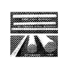
植物系材料として、例えば、針葉樹である杉を用いて当該成形を行うには、図1に示されるダイス金型(押出し比:2.6、ダイス角度 5.45°、ダイス型アール15mm)を100℃以上に加熱し、そこに含水率を調整した杉を押し込む方法が例示される。
ここで、ダイス金型の材質としては、本実施例で使用したSKD11等のSKD(合金工具鋼(ダイス鋼))のほか、ダイス金型の材料として用いられるステンレス鋼等の硬質の金属材料や無機材料等を用いることができる。
軸(繊維)方向に荷重を受けた杉は、ダイス型に押し込まれることで型接触面から向心方向に圧縮力を受けながら断面減少する変形を受けて成形される。
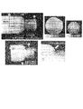
最終的に、直径50mmの杉が直径31mmに絞り成形された高密度化丸棒として成形体が得られる(図2)。
ここで、ダイス金型の材質としては、本実施例で使用したSKD11等のSKD(合金工具鋼(ダイス鋼))のほか、ダイス金型の材料として用いられるステンレス鋼等の硬質の金属材料や無機材料等を用いることができる。
軸(繊維)方向に荷重を受けた杉は、ダイス型に押し込まれることで型接触面から向心方向に圧縮力を受けながら断面減少する変形を受けて成形される。
最終的に、直径50mmの杉が直径31mmに絞り成形された高密度化丸棒として成形体が得られる(図2)。
図2では、外観として素材から成形品にかけて、矢印で示すように木目の連続性が確認され、長手方向に対して横断面変化を与えつつ長手方向の繊維の連続性を維持した状態で、円断面形状への賦形が完了している。
また、成形前の素材断面Aにおいて確認される木目が、成形品の断面Bでは、成形工程での向心方向への圧縮によって間隔が狭くなっており、高密度化されている(特に、成形表面付近でより圧縮度合いの高い状態になっている。)ことがわかる。
また、成形前の素材断面Aにおいて確認される木目が、成形品の断面Bでは、成形工程での向心方向への圧縮によって間隔が狭くなっており、高密度化されている(特に、成形表面付近でより圧縮度合いの高い状態になっている。)ことがわかる。
本発明の成形体の製造方法は、型温度、型表面仕上げ状態、押出し速度、原料含水率、原料樹脂含浸等を設定することにより、成形体の性状等を任意に制御することができる。
例えば、熱硬化性樹脂の表面含浸素材を使用し、ダイス出口の型表面を鏡面仕上げ状態にした加熱絞り成形では、樹脂硬化が完了した成形体の表面は、植物系材料の持つ原材料の本来の木目の連続性を反映させつつ、非常に硬質で滑らかな光沢のある成形品が得られる。
更に、同様のダイス条件でも、型温度及び押出し速度を上げることで、成形体表面の高密度化層の厚さを変化させたり、成形に必要な荷重を低減することも適宜可能である。
例えば、熱硬化性樹脂の表面含浸素材を使用し、ダイス出口の型表面を鏡面仕上げ状態にした加熱絞り成形では、樹脂硬化が完了した成形体の表面は、植物系材料の持つ原材料の本来の木目の連続性を反映させつつ、非常に硬質で滑らかな光沢のある成形品が得られる。
更に、同様のダイス条件でも、型温度及び押出し速度を上げることで、成形体表面の高密度化層の厚さを変化させたり、成形に必要な荷重を低減することも適宜可能である。
従来の植物系材料の成形法では、竹、木材等の植物系材料を1軸プレス用金型に供給して、原材料の風合いを成形体に反映させて、長尺状の任意断面を持つ成形体の連続的な圧縮加工することは困難であった。
これに対し、本発明は、植物系材料を加圧して圧縮(プレス)する場合は、長尺の植物系材料についてダイス型に連続的に押し込むことによって、理論的には無限に長い物体を形成できる。
また、植物系材料を適宜、継ぎ足すことによって成形と同時に接合も可能であり、長尺成形体の連続製造を可能とするものである。
これに対し、本発明は、植物系材料を加圧して圧縮(プレス)する場合は、長尺の植物系材料についてダイス型に連続的に押し込むことによって、理論的には無限に長い物体を形成できる。
また、植物系材料を適宜、継ぎ足すことによって成形と同時に接合も可能であり、長尺成形体の連続製造を可能とするものである。
本発明では、植物系材料を圧縮・絞り成形により、例えば、長尺の圧縮成形体を製造するため、好適には、図1に示されるダイス型に押し込んで材料を加圧するための任意の成形用のダイス角度と押出し比を有するダイス金型と形状固定用のベアリング部で構成される成形手段と、これに付属する加圧手段及び加熱手段を配設した装置が用いられるが、これらの大きさ、具体的な形状、構造及び成形用の横断面の形状等は、その目的製品に応じて任意に設計することができる。
また、ダイス後方から成形体を引き抜くことによって成形前の植物系材料の座屈の発生を防止するとともに、押出し荷重を低減させることも可能である。
また、ダイス後方から成形体を引き抜くことによって成形前の植物系材料の座屈の発生を防止するとともに、押出し荷重を低減させることも可能である。
更に、本発明では、植物系材料の種類、ダイス金型に供給する原料植物系材料の形状及び大きさ、その含水率、押出し荷重、温度時間等の成形条件は、植物系材料の種類、成形体の断面形状及び構造、深底の種類、要求される原料の風合い等に応じて任意に設定することができる。
本発明の方法は、成形手法としては、従来、材料の塑性変形を利用した成形方法として知られている手法であるが、当該方法は、例えば、樹脂等の可塑性の高い材料や流動性の高い材料に適用される成形手法であって、竹や木材のような植物系材料に対しては適用し得ないと考えられていた成形手法であり、本発明者らは、成形の圧力、温度、原料含水率、処理時間等の条件を種々検討した結果、これらの植物系材料であっても、原材料の風合いを付与した形で任意の形態に成形体を製造できることを見出し、植物系材料の新しい成形技術として確立されるに至ったものである。
次に、本発明を実施例に基づいて具体的に説明するが、本発明は、以下の実施例によって何ら限定されるものではない。
杉(針葉樹)から、ダイス金型に挿入可能な大きさ直径50mm以下程度に荒加工した素材を切り出し、それを水浸漬し表面含水状態として押出し実験に供した。
押出し成形には所定のダイス角度、押出し比、ベアリング長さを持つダイス金型による前方押出し成形法を用いた(図1)。
150℃に加熱したダイス金型に素材1個を挿入し、プレスにより直接素材を押し込んで加圧し変形させた。
その後、金型を冷却せずに加圧素材を取り出して断面形状が50mmから31mmに絞られた絞り・圧縮成形体(図2)を得た。
なお、成形に要した時間は約10秒程度であった。
また、得られた成形品部は、図2C及びDのように、ほとんど変色せず、木目の連続性を保っていた。
押出し成形には所定のダイス角度、押出し比、ベアリング長さを持つダイス金型による前方押出し成形法を用いた(図1)。
150℃に加熱したダイス金型に素材1個を挿入し、プレスにより直接素材を押し込んで加圧し変形させた。
その後、金型を冷却せずに加圧素材を取り出して断面形状が50mmから31mmに絞られた絞り・圧縮成形体(図2)を得た。
なお、成形に要した時間は約10秒程度であった。
また、得られた成形品部は、図2C及びDのように、ほとんど変色せず、木目の連続性を保っていた。
杉(針葉樹)から、ダイス金型に挿入可能な大きさ直径50mm以下程度に荒加工した素材を切り出し、それにフェノール樹脂を38%程度含浸して押出し実験に供した。
押出し成形には所定のダイス角度、押出し比、ベアリング長さを持つダイス金型による前方押出し成形法を用いた。
180℃に加熱したダイス金型に素材1個を挿入し、プレスにより直接素材を押し込んで加圧し変形させた。
その後、金型を冷却して加圧素材を取り出して断面形状が50mmから31mmに絞られた絞り・圧縮成形体を得た。
成形品部は、滑らかな表面で光沢を持ち、硬質化されており、木目の連続性を保っていた。
押出し成形には所定のダイス角度、押出し比、ベアリング長さを持つダイス金型による前方押出し成形法を用いた。
180℃に加熱したダイス金型に素材1個を挿入し、プレスにより直接素材を押し込んで加圧し変形させた。
その後、金型を冷却して加圧素材を取り出して断面形状が50mmから31mmに絞られた絞り・圧縮成形体を得た。
成形品部は、滑らかな表面で光沢を持ち、硬質化されており、木目の連続性を保っていた。
桐(広葉樹)から、ダイス金型に挿入可能な大きさ直径50mm以下程度に荒加工した材料を切り出し、それにフェノール樹脂を22%程度含浸して押出し実験に供した。
押出し成形には所定のダイス角度、押出し比、ベアリング長さを持つダイス金型による前方押出し成形法を用いた(図3)。
180℃に加熱したダイス金型に素材1個を挿入し、プレスにより直接素材を押し込んで加圧し変形させた。
その後、金型を冷却して成形体を取り出して断面形状が50mmから31mmに絞られた絞り・圧縮成形体を得た。
成形体は、滑らかな表面で光沢を持ち、硬質化されており、木目の連続性を保っていた。
押出し成形には所定のダイス角度、押出し比、ベアリング長さを持つダイス金型による前方押出し成形法を用いた(図3)。
180℃に加熱したダイス金型に素材1個を挿入し、プレスにより直接素材を押し込んで加圧し変形させた。
その後、金型を冷却して成形体を取り出して断面形状が50mmから31mmに絞られた絞り・圧縮成形体を得た。
成形体は、滑らかな表面で光沢を持ち、硬質化されており、木目の連続性を保っていた。
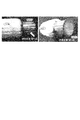
杉(針葉樹)から、ダイス金型に挿入可能な大きさ直径50mm以下程度に荒加工した素材を切り出し、横断面中心付近に長手方向に貫通穴をあけ、その素材にフェノール樹脂を38%程度含浸して押出し実験に供した(図4)。
押出し成形には所定のダイス角度、押出し比、ベアリング長さを持つダイス金型による前方押出し成形法を用いた。
180℃に加熱したダイス金型に素材1個を挿入し、プレスにより直接素材を押し込んで加圧し変形させた。
その後、金型を冷却して成形体を取り出して断面形状が50mmから31mmに絞られると同時に、初期に設けた穴が絞り圧縮とともに閉塞する成形体を得た。
この穴の大きさ、長手方向深さを調整すれば、同一直径の成形品部表面は、滑らかな表面で光沢を持ち、硬質化されており、木目の連続性を保ちつつ、長手方向に密度分布(単位体積あたりの重量)が異なる長尺木質材が得られる。
押出し成形には所定のダイス角度、押出し比、ベアリング長さを持つダイス金型による前方押出し成形法を用いた。
180℃に加熱したダイス金型に素材1個を挿入し、プレスにより直接素材を押し込んで加圧し変形させた。
その後、金型を冷却して成形体を取り出して断面形状が50mmから31mmに絞られると同時に、初期に設けた穴が絞り圧縮とともに閉塞する成形体を得た。
この穴の大きさ、長手方向深さを調整すれば、同一直径の成形品部表面は、滑らかな表面で光沢を持ち、硬質化されており、木目の連続性を保ちつつ、長手方向に密度分布(単位体積あたりの重量)が異なる長尺木質材が得られる。
杉(針葉樹)から、ダイス金型に挿入可能な大きさ直径50mm以下程度に荒加工した素材を切り出し、横断面中心付近に長手方向に貫通穴をあけ、その素材にフェノール樹脂を38%程度含浸して押出し実験に供した。
押出し成形には所定のダイス角度、押出し比、ベアリング長さを持つダイス金型による前方押出し成形法を用いた。
180℃に加熱したダイス金型に素材2個(50mm長さの素材を貫通穴に竹を挿入した状態)を挿入し、プレスにより直接素材を押し込んで加圧し変形させた(図5)。
その後、金型を冷却して加圧素材を取り出して断面形状が50mmから31mmに絞られると同時に、2個の素材が長手方向に接合された絞り・加圧成形体を得た。
成形品部の横断面には、竹と杉が良好に接触しており、竹のしなやかさを絞り・圧縮杉に付与しつつ、成形品部表面は、滑らかな表面で光沢を持ち、硬質化されており、杉木目の連続性を保っていた。
このような方式を繰り返すことにより、長さに制限のない長尺木質製品が得られる。
押出し成形には所定のダイス角度、押出し比、ベアリング長さを持つダイス金型による前方押出し成形法を用いた。
180℃に加熱したダイス金型に素材2個(50mm長さの素材を貫通穴に竹を挿入した状態)を挿入し、プレスにより直接素材を押し込んで加圧し変形させた(図5)。
その後、金型を冷却して加圧素材を取り出して断面形状が50mmから31mmに絞られると同時に、2個の素材が長手方向に接合された絞り・加圧成形体を得た。
成形品部の横断面には、竹と杉が良好に接触しており、竹のしなやかさを絞り・圧縮杉に付与しつつ、成形品部表面は、滑らかな表面で光沢を持ち、硬質化されており、杉木目の連続性を保っていた。
このような方式を繰り返すことにより、長さに制限のない長尺木質製品が得られる。
杉(針葉樹)から、ダイス金型(出口径24mm)に挿入可能な大きさ直径30mm程度に荒加工した素材を用いて押出し実験に供した。このとき、内径25mmで長さ500mmのベアリングを併用することで、図6に示す長尺の絞り・圧縮成形体を得た。このときの押出し比は、1.44(断面減少率は31%)であった。
成形品の横断面は、円周方向から圧縮を受けており、表層部分で高密度化していた。成形品の表面は、滑らかな表面で光沢を持ち、硬質化されており、杉木目の連続性を保っていた。
成形品の横断面は、円周方向から圧縮を受けており、表層部分で高密度化していた。成形品の表面は、滑らかな表面で光沢を持ち、硬質化されており、杉木目の連続性を保っていた。
以上詳述したように、本発明は、植物系材料の成形方法及びその成形体に関するものであり、長尺の植物系材料を任意の押出し比(断面減少率)並びにダイス角度を持つダイス型に押し込み、長軸断面方向に対して植物系材料の組織・細胞をせん断・圧縮して空隙を押し潰しながら連続的に成形させて形状を固定する押出し・絞り成形によって、長尺でありながら軸方向に機械的・物理的性質を制御された任意断面の圧縮成形体を製造し、提供することができる。
Claims (7)
- 繊維方向に長い長尺の植物系材料に対して、所定の押出し比とダイス角を持つ押出用ダイス型を介して、当該材料を押出しながら、材料の中心方向に連続的に植物系材料の構成組織を圧縮・絞り変形を与え、高密度化、高強度化するようにした長尺の植物系材料を得ることを特徴とする植物系材料の成形方法。
- ダイス型の後方に、長手方向に対して横断面変化を与えた治具を配置することで、長手方向の繊維の連続性を維持した状態で、任意形状への賦形を行うようにしたことを特徴とする請求項1に記載の植物系材料の成形方法。
- 成形前の植物系材料に樹脂材料を含浸し、加熱成形を行うようにしたことを特徴とする請求項1に記載の植物系材料の成形方法。
- 成形前の植物系材料が、単一又は複数のバルク体の集合体としてダイス型に供給されるようにしたことを特徴とする請求項1に記載の植物系材料の成形方法。
- 成形前の植物系材料に、その長さ方向に穴を形成し、成形時の長手方向への断面減少率を調整し、成形後の長手方向へのかさ密度の分布を生じせしめ、得られる成形体の重量とそのバランスを制御するようにしたことを特徴とする請求項1に記載の植物系材料の成形方法。
- 成形前の植物系材料に、その長さ方向に穴を形成し、該穴に異種材料を組み込み、一体成形することによって、成形体の内部に異種材料を配置させるようにしたことを特徴とする請求項1に記載の植物系材料の成形方法。
- 長尺の植物系材料からなり、該植物系材料の構成組織が、中心方向に圧縮され、高密度化、高強度化されてなることを特徴とする植物系材料の成形体。
Priority Applications (2)
| Application Number | Priority Date | Filing Date | Title |
|---|---|---|---|
| JP2017564264A JP6750781B2 (ja) | 2016-01-27 | 2017-01-24 | 植物系材料の成形方法及び成形体 |
| US16/071,223 US11691312B2 (en) | 2016-01-27 | 2017-01-24 | Method of molding plant-based material and molded body |
Applications Claiming Priority (2)
| Application Number | Priority Date | Filing Date | Title |
|---|---|---|---|
| JP2016-012904 | 2016-01-27 | ||
| JP2016012904 | 2016-01-27 |
Publications (1)
| Publication Number | Publication Date |
|---|---|
| WO2017130957A1 true WO2017130957A1 (ja) | 2017-08-03 |
Family
ID=59398185
Family Applications (1)
| Application Number | Title | Priority Date | Filing Date |
|---|---|---|---|
| PCT/JP2017/002329 Ceased WO2017130957A1 (ja) | 2016-01-27 | 2017-01-24 | 植物系材料の成形方法及び成形体 |
Country Status (3)
| Country | Link |
|---|---|
| US (1) | US11691312B2 (ja) |
| JP (1) | JP6750781B2 (ja) |
| WO (1) | WO2017130957A1 (ja) |
Cited By (1)
| Publication number | Priority date | Publication date | Assignee | Title |
|---|---|---|---|---|
| JP2023184207A (ja) * | 2022-06-17 | 2023-12-28 | ヤマハ株式会社 | 成形体の製造方法及び成形体 |
Families Citing this family (1)
| Publication number | Priority date | Publication date | Assignee | Title |
|---|---|---|---|---|
| CH718995A1 (fr) * | 2021-09-24 | 2023-03-31 | Creaholic Sa | Procédé de formage du bois. |
Citations (4)
| Publication number | Priority date | Publication date | Assignee | Title |
|---|---|---|---|---|
| JPH0367046U (ja) * | 1989-11-02 | 1991-06-28 | ||
| JP2001026005A (ja) * | 1999-07-13 | 2001-01-30 | Tesac Corp | 柱状圧縮集合木材の製造方法及び柱状圧縮集合木材 |
| JP2003145511A (ja) * | 2002-11-15 | 2003-05-20 | Nakai Sangyo Kk | 国産材、杉・松、間伐材等の木材を原材料とした建材及び木材成形品の製造方法 |
| JP2003231101A (ja) * | 2002-02-07 | 2003-08-19 | Kochi Prefecture | 木材の曲げ加工方法及び木材の曲げ加工装置 |
Family Cites Families (10)
| Publication number | Priority date | Publication date | Assignee | Title |
|---|---|---|---|---|
| JPS58184012A (ja) * | 1982-04-21 | 1983-10-27 | Sankyo Alum Ind Co Ltd | 曲がり形材の製造方法 |
| JPH0567338A (ja) * | 1991-09-06 | 1993-03-19 | Canon Inc | トラツク横断信号生成装置 |
| JPH09155819A (ja) * | 1995-12-11 | 1997-06-17 | Tomiyasu Honda | 圧縮木質材およびその製造方法 |
| JP3580537B2 (ja) * | 2000-07-31 | 2004-10-27 | 独立行政法人産業技術総合研究所 | 木材成形装置および木材成形方法 |
| JP2002146195A (ja) | 2000-11-07 | 2002-05-22 | Fudow Co Ltd | 木質系の熱硬化性樹脂成形材料およびその成形方法 |
| JP2004009567A (ja) | 2002-06-07 | 2004-01-15 | Goto Kensetsu Kk | 圧縮木材の成形方法と、金型装置を利用した圧縮木材 |
| JP4020901B2 (ja) | 2004-09-08 | 2007-12-12 | オリンパス株式会社 | 圧縮成形木材、その製造方法、およびそれを用いた電子機器の外装材 |
| JP2006240032A (ja) * | 2005-03-02 | 2006-09-14 | Kyoto Univ | 水蒸気処理、樹脂含浸処理の複合による、木材の圧密化 |
| JP4849609B2 (ja) * | 2006-08-04 | 2012-01-11 | 独立行政法人産業技術総合研究所 | 植物系材料の成形方法及びその成形体 |
| JP5864078B2 (ja) | 2010-02-12 | 2016-02-17 | 奈良県 | 混練型wpcの製造方法 |
-
2017
- 2017-01-24 JP JP2017564264A patent/JP6750781B2/ja active Active
- 2017-01-24 WO PCT/JP2017/002329 patent/WO2017130957A1/ja not_active Ceased
- 2017-01-24 US US16/071,223 patent/US11691312B2/en active Active
Patent Citations (4)
| Publication number | Priority date | Publication date | Assignee | Title |
|---|---|---|---|---|
| JPH0367046U (ja) * | 1989-11-02 | 1991-06-28 | ||
| JP2001026005A (ja) * | 1999-07-13 | 2001-01-30 | Tesac Corp | 柱状圧縮集合木材の製造方法及び柱状圧縮集合木材 |
| JP2003231101A (ja) * | 2002-02-07 | 2003-08-19 | Kochi Prefecture | 木材の曲げ加工方法及び木材の曲げ加工装置 |
| JP2003145511A (ja) * | 2002-11-15 | 2003-05-20 | Nakai Sangyo Kk | 国産材、杉・松、間伐材等の木材を原材料とした建材及び木材成形品の製造方法 |
Cited By (1)
| Publication number | Priority date | Publication date | Assignee | Title |
|---|---|---|---|---|
| JP2023184207A (ja) * | 2022-06-17 | 2023-12-28 | ヤマハ株式会社 | 成形体の製造方法及び成形体 |
Also Published As
| Publication number | Publication date |
|---|---|
| JP6750781B2 (ja) | 2020-09-02 |
| US11691312B2 (en) | 2023-07-04 |
| JPWO2017130957A1 (ja) | 2018-11-22 |
| US20210170625A1 (en) | 2021-06-10 |
Similar Documents
| Publication | Publication Date | Title |
|---|---|---|
| JP5723964B2 (ja) | 閉断面ビーム要素を製造する方法及び押し出しデバイス | |
| KR102773234B1 (ko) | 분말 사출 성형에 의한 물품 제조 공정 | |
| JP5500541B2 (ja) | 植物系材料の成形体の製造方法及びその成形体 | |
| HU219103B (hu) | Eljárás facellulóz rostos anyagú lemez folyamatos gyártására | |
| JP6750781B2 (ja) | 植物系材料の成形方法及び成形体 | |
| JP4849609B2 (ja) | 植物系材料の成形方法及びその成形体 | |
| CN1504072A (zh) | 一种松散状生物质材料成型模腔及成型机 | |
| CN105965846A (zh) | 一种生物质木塑发泡地板的连续共挤自增强设备及方法 | |
| CN108015923A (zh) | 一种纤维增强热塑性复合材料产品的加工成型工艺 | |
| EP3778163B1 (de) | Verfahren zur herstellung eines holz-formteils | |
| CN107399090B (zh) | 一种纤维增强发泡复合材料及其制造方法 | |
| JP6607965B2 (ja) | 木質成形バット及びその製造方法 | |
| JPH07285105A (ja) | 竹を原材料とした加圧成形品及び加圧成形方法 | |
| JP4502848B2 (ja) | 繊維を有する植物系熱圧成形材料及びその製造方法 | |
| JP2012161933A (ja) | 植物系材料の成形体製造装置 | |
| EP3006175B1 (en) | Method and device for extruding plasticized powdered materials (variants) | |
| JP5550080B2 (ja) | 植物系材料の成形体製造方法及び植物系材料の成形体 | |
| RU2489253C1 (ru) | Способ экструзии пластифицированных порошковых материалов (варианты) и устройство для его осуществления (варианты) | |
| JP7624638B2 (ja) | 木目を有する木質成形体及びその製造方法 | |
| JP5629863B2 (ja) | 熱圧処理木材ならびにその製造方法 | |
| CN101119831A (zh) | 用于制造成形木制品的方法 | |
| JPH0976328A (ja) | 長繊維強化熱可塑性樹脂の押出成形方法及び押出成形装置 | |
| JPWO2003103912A1 (ja) | 木質成形体の製造方法および木質成形体 | |
| JP2011037184A (ja) | 圧密木材複合成形品の成形方法 | |
| FI122690B (fi) | Menetelmä puukuitupitoisen levyn valmistamiseksi |
Legal Events
| Date | Code | Title | Description |
|---|---|---|---|
| 121 | Ep: the epo has been informed by wipo that ep was designated in this application |
Ref document number: 17744187 Country of ref document: EP Kind code of ref document: A1 |
|
| ENP | Entry into the national phase |
Ref document number: 2017564264 Country of ref document: JP Kind code of ref document: A |
|
| NENP | Non-entry into the national phase |
Ref country code: DE |
|
| 122 | Ep: pct application non-entry in european phase |
Ref document number: 17744187 Country of ref document: EP Kind code of ref document: A1 |