WO2017130710A1 - 加工用液の回収システムおよび回収方法 - Google Patents
加工用液の回収システムおよび回収方法 Download PDFInfo
- Publication number
- WO2017130710A1 WO2017130710A1 PCT/JP2017/000763 JP2017000763W WO2017130710A1 WO 2017130710 A1 WO2017130710 A1 WO 2017130710A1 JP 2017000763 W JP2017000763 W JP 2017000763W WO 2017130710 A1 WO2017130710 A1 WO 2017130710A1
- Authority
- WO
- WIPO (PCT)
- Prior art keywords
- processing liquid
- mist collector
- processing
- storage tank
- cutting oil
- Prior art date
- Legal status (The legal status is an assumption and is not a legal conclusion. Google has not performed a legal analysis and makes no representation as to the accuracy of the status listed.)
- Ceased
Links
Images

Classifications
-
- B—PERFORMING OPERATIONS; TRANSPORTING
- B01—PHYSICAL OR CHEMICAL PROCESSES OR APPARATUS IN GENERAL
- B01D—SEPARATION
- B01D46/00—Filters or filtering processes specially modified for separating dispersed particles from gases or vapours
-
- B—PERFORMING OPERATIONS; TRANSPORTING
- B01—PHYSICAL OR CHEMICAL PROCESSES OR APPARATUS IN GENERAL
- B01D—SEPARATION
- B01D46/00—Filters or filtering processes specially modified for separating dispersed particles from gases or vapours
- B01D46/42—Auxiliary equipment or operation thereof
-
- B—PERFORMING OPERATIONS; TRANSPORTING
- B23—MACHINE TOOLS; METAL-WORKING NOT OTHERWISE PROVIDED FOR
- B23Q—DETAILS, COMPONENTS, OR ACCESSORIES FOR MACHINE TOOLS, e.g. ARRANGEMENTS FOR COPYING OR CONTROLLING; MACHINE TOOLS IN GENERAL CHARACTERISED BY THE CONSTRUCTION OF PARTICULAR DETAILS OR COMPONENTS; COMBINATIONS OR ASSOCIATIONS OF METAL-WORKING MACHINES, NOT DIRECTED TO A PARTICULAR RESULT
- B23Q11/00—Accessories fitted to machine tools for keeping tools or parts of the machine in good working condition or for cooling work; Safety devices specially combined with or arranged in, or specially adapted for use in connection with, machine tools
- B23Q11/10—Arrangements for cooling or lubricating tools or work
-
- B—PERFORMING OPERATIONS; TRANSPORTING
- B23—MACHINE TOOLS; METAL-WORKING NOT OTHERWISE PROVIDED FOR
- B23Q—DETAILS, COMPONENTS, OR ACCESSORIES FOR MACHINE TOOLS, e.g. ARRANGEMENTS FOR COPYING OR CONTROLLING; MACHINE TOOLS IN GENERAL CHARACTERISED BY THE CONSTRUCTION OF PARTICULAR DETAILS OR COMPONENTS; COMBINATIONS OR ASSOCIATIONS OF METAL-WORKING MACHINES, NOT DIRECTED TO A PARTICULAR RESULT
- B23Q11/00—Accessories fitted to machine tools for keeping tools or parts of the machine in good working condition or for cooling work; Safety devices specially combined with or arranged in, or specially adapted for use in connection with, machine tools
-
- B—PERFORMING OPERATIONS; TRANSPORTING
- B24—GRINDING; POLISHING
- B24B—MACHINES, DEVICES, OR PROCESSES FOR GRINDING OR POLISHING; DRESSING OR CONDITIONING OF ABRADING SURFACES; FEEDING OF GRINDING, POLISHING, OR LAPPING AGENTS
- B24B55/00—Safety devices for grinding or polishing machines; Accessories fitted to grinding or polishing machines for keeping tools or parts of the machine in good working condition
- B24B55/12—Devices for exhausting mist of oil or coolant; Devices for collecting or recovering materials resulting from grinding or polishing, e.g. of precious metals, precious stones, diamonds or the like
Definitions
- the present invention relates to a processing liquid recovery system and recovery method for recovering and reusing a mist of processing fluid such as cutting oil and grinding oil generated during operation of a processing machine such as a machine tool.
- cutting fluid containing oil as the main component and cutting fluid containing water as the main component are sprayed onto the tool and workpiece to reduce friction between the workpiece and the tool. In addition, it suppresses overheating and covers it with a so-called splash cover to prevent scattering of cutting oil and cutting waste.
- the cutting oil sprayed toward the workpiece or the like is collected in the cutting oil tank and reused, but a part of the cutting oil is misted by mixing with air.
- an oil mist collector is used (see, for example, Patent Document 1).
- the oil mist collector takes the air containing the oil mist in the splash cover into the main body with a negative pressure inside the lumen with a fan motor, gas-liquid separation with a filter, and traps the separated gas at the bottom of the main body while exhausting the separated gas. Collected cutting oil is discharged to the outside by its own weight. The cutting oil collected by the oil mist collector is collected in the processing liquid tank and reused.
- Patent Document 1 discloses a method in which the container is screwed into the bottom surface of the oil mist collector main body while being sealed with packing, and gas intrusion into the oil mist collector drain is prevented by the cutting oil accumulated in the container. is doing.
- oil mist collectors tend to accumulate sludge, it is necessary to periodically disassemble and maintain them frequently.
- the oil reservoir is attached to the oil mist collector body.
- One of the objects of the present invention is to use various kinds of cutting oil, cutting fluid, grinding fluid, grinding fluid, polishing fluid, polishing fluid, etc., used in processing of a processing machine that performs cutting, grinding, polishing, etc. of a workpiece.
- An object of the present invention is to provide a processing liquid recovery system and recovery method capable of significantly improving the efficiency of maintenance work of a mist collector for recovery while reliably recovering mist generated from the processing liquid.
- the recovery system of the present invention collects gas containing mist generated from the processing liquid in the processing chamber by a mist collector in the processing machine that recovers the processing liquid supplied from the storage tank into the processing chamber in the storage tank.
- a processing liquid recovery system for recovering the processing liquid obtained by gas-liquid separation in the storage tank using its own weight, An opening for receiving a discharge pipe extending from the mist collector for guiding the processing liquid collected at the bottom of the mist collector downward, a lumen for storing the processing liquid, and the discharge disposed in the lumen
- a movable container independent of the mist collector One end is connected to the discharge port, and the other end is located at a position where the processing liquid can be discharged directly to the storage tank or can be discharged from the processing chamber to the storage path for the processing liquid.
- An arranged collection tube It is characterized by
- the recovery method of the present invention is a processing machine that recovers a processing liquid supplied from a storage tank into a processing chamber to the storage tank, and collects a gas containing mist generated from the processing liquid in the processing chamber by a mist collector.
- the other end of the recovery pipe having one end connected to the discharge port can be discharged directly into the storage tank, or discharged from the processing chamber into the storage path for the processing liquid to the storage tank. It arrange
- the container for collecting and storing the processing liquid collected by the mist collector is movable independently of the mist collector, so that when the mist collector is maintained, the processing liquid is already in the container.
- the efficiency of the maintenance operation of the mist collector is greatly improved, and the field environment is not polluted.
- the container for collecting the processing liquid is movable, the degree of freedom of arrangement of the mist collector is increased, and it becomes possible to install the mist collector at a position where maintenance work is easy, A single mist collector can be commonly used for mist collection of a plurality of processing machines.
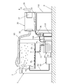
- FIG. 1 is a schematic view of a processing liquid recovery system according to an embodiment of the present invention. Schematic of the process liquid collection
- FIG. 1 is a schematic view of a processing liquid recovery system according to an embodiment of the present invention.
- the “working liquid” is used for lubrication, cooling, etc. when machining a workpiece such as a machining process by a machining center, a lathe, a grinding process by a grinding machine, or an abrasive process by a polishing machine.
- This includes oily liquids such as various cutting oils and grinding oils used in the field, and cutting liquids and grinding liquids mainly composed of water, and liquids that require mist to be collected during processing.
- this embodiment demonstrates the case where cutting oil is used as a process liquid.
- FIG. 1 is a schematic view of a processing liquid recovery system according to an embodiment of the present invention.
- the “working liquid” is used for lubrication, cooling, etc. when machining a workpiece such as a machining process by a machining center, a lathe, a grinding process by a grinding machine, or an abrasive process by a polish
- the machine tool 1 installed on the reference plane B is, for example, a machining center, but the machine body is not shown for convenience of explanation.
- the processing chamber 2 is a closed space defined by a splash cover (not shown), and a workpiece is cut in the processing chamber 2.
- a storage tank 40 for storing the cutting oil ML and an injection pump 50 for injecting the cutting oil are installed on the reference surface B below the processing chamber 2.
- the injection pump 50 discharges the cutting oil ML supplied from the storage tank 40 through the communication pipe 51 to the discharge pipe 52.
- the end of the discharge pipe 52 is provided in the processing chamber 2, and the cutting oil ML is sprayed from a spray nozzle 53 connected to the end of the discharge pipe 52 toward a workpiece or a cutting tool (not shown).
- the bottom surface 3 of the processing chamber 2 is inclined toward the discharge port 4 so that the cutting oil ML falling after being sprayed from the spray nozzle 53 can be received and collected at the discharge port 4.
- One end of the recovery pipe 11 is connected to the discharge port 4, and the other end of the recovery pipe 11 is connected to the upper part of the storage tank 40. Thereby, the cutting oil ML collected at the discharge port 4 falls into the collection pipe 11 by its own weight, is collected into the storage tank 40 through the collection pipe 11, and is used again for cutting.
- an oil mist collector 30 is disposed in the upper part of the processing chamber 2, and the intake port 31 of the oil mist collector 30 communicates with the upper part of the processing chamber 2 by the duct 10.
- the oil mist collector 30 has a fume filter 35 and a fan motor 37 in its inner cavity 33.
- the fume filter 35 is provided in the immediate vicinity of the intake port 31.
- the fan motor 37 is a motor-driven fan, and exhausts the gas G in the lumen 33 of the oil mist collector 30 to the exhaust pipe 39. Due to the exhaust action of the fan motor 37, the inner cavity 33 of the oil mist collector 30 is maintained at a negative pressure.
- a discharge pipe 38 is connected to the discharge port 36 of the oil mist collector 30.
- the discharge pipe 38 is provided so as to guide the cutting oil ML discharged from the discharge port 36 using its own weight downward.
- the discharge pipe 38 can be a resin-made flexible tube or a metal tube, but is provided so as not to hinder the flow of the cutting oil ML that falls by its own weight from the discharge port 36.
- the container 100 is a bottomed cylindrical member, and the material is not particularly limited, but is made of metal in the present embodiment.
- the container 100 has an opening 101 at the upper end, and has a lumen 102 for storing the cutting oil ML inside. Furthermore, when the level of the liquid level LS1 of the stored cutting oil ML reaches a predetermined overflow level OFL, the side wall surface of the container 100 has a discharge port 103 for overflowing the cutting oil ML to the outside.
- a pipe joint 104 is provided outside the discharge port 103.
- the position of the liquid level LS2 of the cutting oil ML in the discharge pipe 38 is lower than the level of the liquid level LS1 of the cutting oil ML in the container 100 because the lumen 33 has a negative pressure while the oil mist collector 30 is operating. Is also in a high position.
- One end 120a of the recovery pipe 120 is detachably fitted into the pipe joint 104.
- the material for forming the collection tube 120 is not particularly limited, but it is preferable to use a flexible resin tube because the other end 120b of the collection tube 120 can be disposed at an arbitrary position.
- the other end 120b of the recovery pipe 120 can be disposed at any position as long as the cutting oil ML can be recovered in the storage tank 40 using its own weight, but in this embodiment, the container 100 is installed.
- the cutting oil ML discharged from the other end 120 b of the recovery pipe 120 falls to the bottom surface 3, then moves on the inclined bottom surface 3 by its own weight toward the discharge port 4, and is recovered in the storage tank 40 through the recovery pipe 11.
- the arrangement of the other end 120b of the recovery pipe 120 can be arbitrarily selected, the length of the recovery pipe 120 can be minimized.
- the container 100 can be moved independently of the arrangement of the oil mist collector 30 and can be arranged at an arbitrary height.
- the discharge port 103 of the container 100 is positioned lower than the oil mist collector 30, and the discharge port 103 of the container 100 is positioned higher than the storage tank 40. What is necessary is just to arrange.
- the container 100 can receive the distal end portion 38 a of the discharge tube 38 in the inner cavity 102 through the opening 101.
- the distal end portion 38a of the discharge pipe 38 is disposed in the cutting oil ML accumulated in the lumen 102, and the distal end portion 38a does not open to the atmosphere.
- the cutting oil ML does not exist in the inner cavity 102 of the container 100. Therefore, the cutting oil ML is supplied from the outside in advance, and the distal end portion 38a of the discharge pipe 38 is always immersed in the cutting oil ML. It is preferable to keep it in a state.
- the container 100 for storing the collected cutting oil ML is provided independently of the oil mist collector 30 and is movable independently of the oil mist collector 30. Since all of the cutting oil ML collected by the oil mist collector 30 is collected in the container 100, a large amount of cutting oil ML does not leak even if the oil mist collector 30 is disassembled during maintenance work. If necessary, the workability of the maintenance work is further improved by moving the container 100 to a place away from the place where the maintenance work is performed. Further, according to the present embodiment, the bottom surface of the oil mist collector 30 is flat and does not have a protruding portion, so that it can be easily installed on the top surface of the machine tool 1.
- the oil mist collector 30 is arranged at a lower position than the upper part of the machine tool 1.
- the oil mist collector 30 is supported by a support base 150 having a predetermined height.
- the efficiency of the maintenance work of the oil mist collector 30 can be greatly improved. Since the oil mist collector 30 is disposed on the upper side of the machine tool 1, it is necessary to perform maintenance work by climbing up to the upper part of the machine tool 1 using a ladder or the like.
- the oil mist collector 30 is arranged at a height at which the maintenance work can be performed on the reference plane B without climbing the upper part of the machine tool 1 using a ladder or the like, the maintenance work is further facilitated. . Further, there is no need to work from the bottom side of the oil mist collector 30, and it is advantageous in that the work can be done from the side.
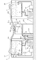
- the processing chambers 2 of a plurality of (two) machine tools 1A and 1B are connected to a common oil mist collector 30A via ducts 10A and 10B, respectively.
- the oil mist collector 30A has an intake port 31A in the ceiling portion, to which a T-shaped pipe joint 34 is connected.
- Ducts 10 ⁇ / b> A and 10 ⁇ / b> B are connected to the T-shaped pipe joint 34.
- a fume filter 35A is provided in the immediate vicinity of the intake port 31A.
- the oil mist collector 30A is arranged at a lower position than the upper parts of the machine tools 1A and 1B.
- the oil mist collector 30A is supported by a support base 150 having a predetermined height.
- the cutting oil ML collected in the container 100 is directly collected in a storage tank 40 provided in one machine tool 1A.
- the oil mist collector 30A common to the plurality of machine tools 1A and 1B is used for maintenance work.
- the total man-hours required can be greatly reduced. That is, when an oil mist collector is provided for each machine tool, maintenance work for the oil mist collectors corresponding to the number of machine tools is required, but in this embodiment, only maintenance work for the oil mist collector 30A is required.
- a cutting machine such as a machining center has been described as an example.
- the application target of the present invention is not limited to this, and includes various processes such as grinding and polishing.
- processing fluid oil-based cutting oil has been given as an example.
- the present invention is not limited to this, and it is not limited to this. It is included in the object of the invention.
Landscapes
- Chemical & Material Sciences (AREA)
- Chemical Kinetics & Catalysis (AREA)
- Engineering & Computer Science (AREA)
- Mechanical Engineering (AREA)
- Auxiliary Devices For Machine Tools (AREA)
Abstract
【課題】被加工物の切削、研削、研摩等を行う加工機械の加工に用いられる、切削油等の各種の加工用液から生じたミストを確実に回収しつつ、ミストコレクタのメンテナンス作業の効率を大幅に改善する。 【解決手段】ミストコレクタ(30)の底部(32)に集められた切削油(ML)を下方に導くミストコレクタ(30)から延びる排出管(38)を受容可能な開口部(101)と、切削油(ML)を貯留する内腔(102)と、排出管(38)の先端部が当該内腔(102)に貯留された切削油(ML)に浸漬された状態において当該切削油の液面レベルが一定レベルを超えるとオーバーフローさせるための排出口(103)とを有するミストコレクタ(30)とは独立に可動の容器(100)と、一端部(120a)が排出口(38)に接続され貯留タンク(40)への回収経路に排出可能に他端部(120b)が配置された回収管(120)とを有する。
Description
本発明は、工作機械等の加工機械の稼働中に生じる、切削油、研削油等の加工用液のミストを回収して再利用する加工用液の回収システムおよび回収方法に関する。
マシニングセンタ等の工作機械では、油を主成分とした切削油や水を主成分とした切削液(以下、切削油と呼ぶ)を工具およびワークに噴射して、ワークおよび工具との摩擦を軽減し、過熱を抑制し、いわゆるスプラッシュカバーで覆って切削油や切削屑の飛散を防いでいる。ワーク等に向けて噴射された切削油は切削油タンクに回収されて再利用されるが、切削油の一部は空気と混ざることによってミスト化する。このオイルミストを捕集するために、オイルミストコレクタが用いられる(例えば、特許文献1参照)。オイルミストコレクタは、スプラッシュカバー内のオイルミストを含む空気を、ファンモータで内腔を負圧にした本体に取り込み、フィルターで気液分離し、分離した気体を排気しつつ本体内の底部に捕集した切削油を自重により外部に排出する。オイルミストコレクタで捕集された切削油は、加工用液タンクに回収されて再利用される。
ここで、特許文献1にも開示されているように、オイルミストコレクタの内部を負圧に保ってオイルミストを安定的かつ効率的に捕集するためには、切削油の排出経路を通じてオイルミストコレクタの本体内に外気が侵入するのを防ぐ必要がある。このため、特許文献1では、パッキンでシールしつつ容器をオイルミストコレクタ本体の底面にねじ込み装着し、オイルミストコレクタの排油口への気体の侵入を容器に溜めた切削油で防ぐ方法を開示している。
しかしながら、オイルミストコレクタは、スラッジが溜まりやすいため、高頻度で定期的に分解してメンテナンスする必要があり、特許文献1のような構造では、油を溜めた容器をオイルミストコレクタ本体に対して着脱しなければならず、着脱作業に非常に手間がかかりメンテナンス作業の効率が悪く、また、メンテナンス作業中に油により現場環境が汚染されやすい。さらに、特許文献1のねじ込み式構造では、容器とオイルミストコレクタ本体との間のシールの経年劣化により、油漏れが発生する可能性がある。
加えて、通常、オイルミストコレクタで捕集した切削油を、自重を利用して切削油タンクに回収するため、工作機械の上方にオイルミストコレクタを設置するが、オイルミストコレクタ本体の底面から容器が突出していると、より大きな設置スペースが必要となる。また、容器が装着されるとともに高い位置に設置されたオイルミストコレクタは、メンテナンス作業の作業性をさらに悪化させる。
しかしながら、オイルミストコレクタは、スラッジが溜まりやすいため、高頻度で定期的に分解してメンテナンスする必要があり、特許文献1のような構造では、油を溜めた容器をオイルミストコレクタ本体に対して着脱しなければならず、着脱作業に非常に手間がかかりメンテナンス作業の効率が悪く、また、メンテナンス作業中に油により現場環境が汚染されやすい。さらに、特許文献1のねじ込み式構造では、容器とオイルミストコレクタ本体との間のシールの経年劣化により、油漏れが発生する可能性がある。
加えて、通常、オイルミストコレクタで捕集した切削油を、自重を利用して切削油タンクに回収するため、工作機械の上方にオイルミストコレクタを設置するが、オイルミストコレクタ本体の底面から容器が突出していると、より大きな設置スペースが必要となる。また、容器が装着されるとともに高い位置に設置されたオイルミストコレクタは、メンテナンス作業の作業性をさらに悪化させる。
本発明の目的の一つは、被加工物の切削、研削、研摩等を行う加工機械の加工に用いられる、切削油、切削液、研削油、研削液、研摩油、研摩液等の各種の加工用液から生じたミストを確実に回収しつつ、回収のためのミストコレクタのメンテナンス作業の効率を大幅に改善可能な加工用液の回収システムおよび回収方法を提供することにある。
本発明の回収システムは、貯留タンクから加工室内に供給された加工用液を前記貯留タンクに回収する加工機械において、前記加工室内において加工用液から生じたミストを含むガスをミストコレクタにより収集して気液分離して得られた加工用液をその自重を利用して前記貯留タンクに回収する、加工用液の回収システムであって、
前記ミストコレクタの底部に集められた加工用液を下方に導く前記ミストコレクタから延びる排出管を受容する開口部と、加工用液を貯留する内腔と、前記内腔内に配置された前記排出管の先端部が当該内腔に貯留された加工用液に浸漬された状態において当該加工用液の液面のレベルが一定レベルを超えると加工用液をオーバーフローさせるための排出口とを有し、前記ミストコレクタとは独立に可動の容器と、
一端部が前記排出口に接続され、加工用液を前記貯留タンクへ直接的に排出可能又は前記加工室から前記貯留タンクへの前記加工用液の回収経路に排出可能な位置に他端部が配置された回収管と、
を有することを特徴とする。
前記ミストコレクタの底部に集められた加工用液を下方に導く前記ミストコレクタから延びる排出管を受容する開口部と、加工用液を貯留する内腔と、前記内腔内に配置された前記排出管の先端部が当該内腔に貯留された加工用液に浸漬された状態において当該加工用液の液面のレベルが一定レベルを超えると加工用液をオーバーフローさせるための排出口とを有し、前記ミストコレクタとは独立に可動の容器と、
一端部が前記排出口に接続され、加工用液を前記貯留タンクへ直接的に排出可能又は前記加工室から前記貯留タンクへの前記加工用液の回収経路に排出可能な位置に他端部が配置された回収管と、
を有することを特徴とする。
本発明の回収方法は、貯留タンクから加工室内に供給された加工用液を前記貯留タンクに回収する加工機械において、前記加工室内において加工用液から生じたミストを含むガスをミストコレクタにより収集して気液分離して得られた加工用液をその自重を利用して前記貯留タンクに回収する、加工用液の回収方法であって、
前記ミストコレクタとは独立に可動な容器の開口部を通じて、前記ミストコレクタの底部に集められた加工用液を下方に導く前記ミストコレクタから延びる排出管の先端部を、当該容器に貯留された加工用液内に配置し、
前記ミストコレクタから延びる排出管から供給された、一定レベルを超える加工用液を前記容器の排出口からオーバーフローさせ、
一端部が前記排出口に接続された回収管の他端部を、加工用液を前記貯留タンクへ直接的に排出可能又は前記加工室から前記貯留タンクへの前記加工用液の回収経路に排出可能な位置に配置して、前記ミストコレクタで集めた加工用液を前記貯留タンクへ回収する、ことを特徴とする。
前記ミストコレクタとは独立に可動な容器の開口部を通じて、前記ミストコレクタの底部に集められた加工用液を下方に導く前記ミストコレクタから延びる排出管の先端部を、当該容器に貯留された加工用液内に配置し、
前記ミストコレクタから延びる排出管から供給された、一定レベルを超える加工用液を前記容器の排出口からオーバーフローさせ、
一端部が前記排出口に接続された回収管の他端部を、加工用液を前記貯留タンクへ直接的に排出可能又は前記加工室から前記貯留タンクへの前記加工用液の回収経路に排出可能な位置に配置して、前記ミストコレクタで集めた加工用液を前記貯留タンクへ回収する、ことを特徴とする。
本発明によれば、ミストコレクタで集めた加工用液を回収して貯留する容器をミストコレクタとは別個独立に可動としたので、ミストコレクタをメンテナンスする際には、加工用液は既に容器に回収されており、加えて、容器はミストコレクタとは独立しているので、ミストコレクタのメンテナンス作業の効率が大幅に改善され、現場環境が汚染されない。
また、本発明によれば、加工用液を回収する容器が可動であるので、ミストコレクタの配置の自由度が増し、ミストコレクタをメンテナンス作業しやすい位置に設置することが可能になり、また、単一のミストコレクタを複数の加工機械のミスト回収に共通に使用可能となる。
また、本発明によれば、加工用液を回収する容器が可動であるので、ミストコレクタの配置の自由度が増し、ミストコレクタをメンテナンス作業しやすい位置に設置することが可能になり、また、単一のミストコレクタを複数の加工機械のミスト回収に共通に使用可能となる。
以下に添付図面を参照しながら、本発明の実施形態について詳細に説明する。なお、本明細書及び図面において、実質的に同一の機能構成を有する構成要素については、同一の符号を付することにより重複説明を省略する。
第1実施形態
図1を参照して本発明の第1の実施形態について説明する。
図1は本発明の一実施形態に係る加工用液の回収システムの概略図である。
なお、本発明において、「加工用液」とは、マシニングセンタ、旋盤等による切削加工や、研削盤等による研削加工、研摩機等による研摩加工などワークを加工する際に、潤滑、冷却などを目的に使用される各種の切削油や研削油等の油性の液体や、水を主成分とした切削液や研削液等を含み、加工中にミストが生じて回収する必要がある液体を含む。また、本実施形態では、加工用液として、切削油を用いる場合について説明する。
図1において、基準面B上に設置された工作機械1は、例えば、マシニングセンタであるが、説明の便宜上、マシン本体の図示は省略する。加工室2は、図示しないスプラッシュカバーで画定される閉空間であり、この加工室2内でワークの切削加工が行われる。
加工室2の下方の基準面B上には、切削油MLを貯留する貯留タンク40および切削油を噴射するための噴射ポンプ50が設置されている。噴射ポンプ50は、連通管51を通じて貯留タンク40から供給される切削油MLを、吐出管52に吐出する。吐出管52の端部は、加工室2内に設けられており、吐出管52の端部に接続された噴射ノズル53から、図示しないワークや切削工具に向けて切削油MLが噴射される。
図1を参照して本発明の第1の実施形態について説明する。
図1は本発明の一実施形態に係る加工用液の回収システムの概略図である。
なお、本発明において、「加工用液」とは、マシニングセンタ、旋盤等による切削加工や、研削盤等による研削加工、研摩機等による研摩加工などワークを加工する際に、潤滑、冷却などを目的に使用される各種の切削油や研削油等の油性の液体や、水を主成分とした切削液や研削液等を含み、加工中にミストが生じて回収する必要がある液体を含む。また、本実施形態では、加工用液として、切削油を用いる場合について説明する。
図1において、基準面B上に設置された工作機械1は、例えば、マシニングセンタであるが、説明の便宜上、マシン本体の図示は省略する。加工室2は、図示しないスプラッシュカバーで画定される閉空間であり、この加工室2内でワークの切削加工が行われる。
加工室2の下方の基準面B上には、切削油MLを貯留する貯留タンク40および切削油を噴射するための噴射ポンプ50が設置されている。噴射ポンプ50は、連通管51を通じて貯留タンク40から供給される切削油MLを、吐出管52に吐出する。吐出管52の端部は、加工室2内に設けられており、吐出管52の端部に接続された噴射ノズル53から、図示しないワークや切削工具に向けて切削油MLが噴射される。
加工室2の底面3は、噴射ノズル53から噴射された後に落下する切削油MLを受け止めて排出口4に集めることができるように、排出口4に向かって傾斜している。排出口4には、回収管11の一端が接続され、回収管11の他端は、貯留タンク40の上部に接続されている。これにより、排出口4に集められた切削油MLは、回収管11内に自重により落下し、回収管11を通じて貯留タンク40内に回収され、再び、切削加工に利用される。
ここで、噴射ノズル53から噴射された切削油MLの一部は、ガスGと混ざることでオイルミストMSとなる。オイルミストMSを放置しておくと、これが加工室2から外部に漏れて現場環境を汚染する可能性がある。このため、加工室2の上部には、オイルミストコレクタ30が配置され、オイルミストコレクタ30の取り込み口31は加工室2の上部とダクト10によって連通している。
オイルミストコレクタ30は、その内腔33内に、ヒュームフィルター35およびファンモータ37を有している。ヒュームフィルター35は取り込み口31の直近に設けられ、加工室2内のオイルミストMSを含むガスGが内腔33内に吸い込まれる際に、気液分離機能により、ガスGとオイルミストMSを分離する。分離されたオイルミストMSは、オイルミストコレクタ30の底面32に切削油MLとして集められる。底面32は、排出口36に向けて傾斜しており、底面32に落下した切削油MLは、自重を利用して排出口36に向けて移動する。
ファンモータ37は、モータ駆動のファンであり、オイルミストコレクタ30の内腔33のガスGを排気管39に排気する。ファンモータ37の排気作用により、オイルミストコレクタ30の内腔33は負圧に保たれる。ここで重要なことは、オイルミストコレクタ30の内腔33を負圧に保つためには、排出口36を通じて外部から空気を侵入させないことである。内腔33が排出口36を通じて大気に開放されていると、オイルミストコレクタ30の内腔33の圧力が大気圧にほぼ等しくなり、加工室2内のオイルミストMSを含むガスGをオイルミストコレクタ30内に効率よく吸引できなくなるからである。
オイルミストコレクタ30は、その内腔33内に、ヒュームフィルター35およびファンモータ37を有している。ヒュームフィルター35は取り込み口31の直近に設けられ、加工室2内のオイルミストMSを含むガスGが内腔33内に吸い込まれる際に、気液分離機能により、ガスGとオイルミストMSを分離する。分離されたオイルミストMSは、オイルミストコレクタ30の底面32に切削油MLとして集められる。底面32は、排出口36に向けて傾斜しており、底面32に落下した切削油MLは、自重を利用して排出口36に向けて移動する。
ファンモータ37は、モータ駆動のファンであり、オイルミストコレクタ30の内腔33のガスGを排気管39に排気する。ファンモータ37の排気作用により、オイルミストコレクタ30の内腔33は負圧に保たれる。ここで重要なことは、オイルミストコレクタ30の内腔33を負圧に保つためには、排出口36を通じて外部から空気を侵入させないことである。内腔33が排出口36を通じて大気に開放されていると、オイルミストコレクタ30の内腔33の圧力が大気圧にほぼ等しくなり、加工室2内のオイルミストMSを含むガスGをオイルミストコレクタ30内に効率よく吸引できなくなるからである。
オイルミストコレクタ30の排出口36には、排出管38が接続されている。排出管38は、排出口36から自重を利用して排出される切削油MLを下方に導くように設けられている。排出管38には、樹脂製の可撓性のチューブや、金属製のチューブを使用できるが、排出口36から自重で落下する切削油MLの流れを妨げないように設けられる。
容器100は、有底の筒状部材であり、材料は特に限定されないが、本実施例では、金属製である。容器100は、上端部に開口部101を有し、内部に切削油MLを溜めるための内腔102を有する。さらに、貯留する切削油MLの液面LS1のレベルが所定のオーバーフローレベルOFLに達すると、切削油MLを外部にオーバーフローさせるための排出口103を容器100の側壁面に有する。この排出口103の外側には、管継手104が設けられている。なお、排出管38内の切削油MLの液面LS2の位置は、オイルミストコレクタ30を稼働中は内腔33が負圧になるので、容器100内の切削油MLの液面LS1のレベルよりも高い位置にある。
管継手104には、回収管120の一端部120aが着脱自在に嵌合挿入されている。回収管120の形成材料は特に限定されないが、回収管120の他方端部120bを任意の位置に配置できることから、可撓性の樹脂製チューブを用いることが好ましい。回収管120の他方端部120bは、貯留タンク40に切削油MLを、自重を利用して回収できる位置であればいずれの位置にも配置可能であるが、本実施形態では、容器100を設置した側の加工室2の底面3上に配置している。回収管120の他方端部120bから排出される切削油MLは、底面3に落下した後、傾斜した底面3を排出口4に向かって自重で移動し、回収管11を通じて貯留タンク40に回収される。このように、回収管120の他方端部120bの配置を任意に選択できるので、回収管120の長さを最小限にすることができる。
管継手104には、回収管120の一端部120aが着脱自在に嵌合挿入されている。回収管120の形成材料は特に限定されないが、回収管120の他方端部120bを任意の位置に配置できることから、可撓性の樹脂製チューブを用いることが好ましい。回収管120の他方端部120bは、貯留タンク40に切削油MLを、自重を利用して回収できる位置であればいずれの位置にも配置可能であるが、本実施形態では、容器100を設置した側の加工室2の底面3上に配置している。回収管120の他方端部120bから排出される切削油MLは、底面3に落下した後、傾斜した底面3を排出口4に向かって自重で移動し、回収管11を通じて貯留タンク40に回収される。このように、回収管120の他方端部120bの配置を任意に選択できるので、回収管120の長さを最小限にすることができる。
容器100は、支持台110により支持されているが、容器100はオイルミストコレクタ30の配置とは独立に移動可能であり、また、任意の高さに配置できる。容器100からオーバーフローした切削油MLを貯留タンク40に戻すためには、容器100の排出口103をオイルミストコレクタ30より低い位置するとともに、容器100の排出口103を貯留タンク40よりも高い位置に配置すればよい。
容器100は、その開口部101を通じて排出管38の先端部38aを内腔102内に受容可能となっている。排出管38の先端部38aは、内腔102に溜めた切削油ML内に配置され、先端部38aは大気に開放しない。これにより、オイルミストコレクタ30内に排出管38および排出口36を通じて気体が侵入するのを防ぐことができる。なお、容器100の内腔102には、初期状態において、切削油MLは存在しないので、あらかじめ外部から切削油MLを供給して排出管38の先端部38aが切削油ML内に常時浸漬された状態にしておくことが好ましい。
容器100は、その開口部101を通じて排出管38の先端部38aを内腔102内に受容可能となっている。排出管38の先端部38aは、内腔102に溜めた切削油ML内に配置され、先端部38aは大気に開放しない。これにより、オイルミストコレクタ30内に排出管38および排出口36を通じて気体が侵入するのを防ぐことができる。なお、容器100の内腔102には、初期状態において、切削油MLは存在しないので、あらかじめ外部から切削油MLを供給して排出管38の先端部38aが切削油ML内に常時浸漬された状態にしておくことが好ましい。
オイルミストコレクタ30は、使用状況にもよるが、内部にスラッジが溜まるため、通常は1~2か月程の周期で、分解清掃するメンテナンス作業が必要である。
本実施形態では、捕集した切削油MLを溜めるための容器100をオイルミストコレクタ30とは別個独立に設け、しかも、オイルミストコレクタ30とは独立に可動としている。オイルミストコレクタ30が捕集した切削油MLは容器100にすべて回収されているので、メンテナンス作業の際に、オイルミストコレクタ30を分解したとしても大量の切削油MLが漏れ出すことがなく、また、必要に応じて、容器100をメンテナンス作業する場所から離れた場所に移動させておくことで、メンテナンス作業の作業性がより向上する。
また、本実施形態によれば、オイルミストコレクタ30の底面は平坦で、突出部がないので、工作機械1の上面に容易に設置可能である。
本実施形態では、捕集した切削油MLを溜めるための容器100をオイルミストコレクタ30とは別個独立に設け、しかも、オイルミストコレクタ30とは独立に可動としている。オイルミストコレクタ30が捕集した切削油MLは容器100にすべて回収されているので、メンテナンス作業の際に、オイルミストコレクタ30を分解したとしても大量の切削油MLが漏れ出すことがなく、また、必要に応じて、容器100をメンテナンス作業する場所から離れた場所に移動させておくことで、メンテナンス作業の作業性がより向上する。
また、本実施形態によれば、オイルミストコレクタ30の底面は平坦で、突出部がないので、工作機械1の上面に容易に設置可能である。
第2実施形態
図2を参照して本発明の第2の実施形態について説明する。なお、図1において、第1の実施形態と同様の構成部分には同一の符号を使用している。
本実施形態では、オイルミストコレクタ30を工作機械1の上部ではなく、より下方の位置に配置している。オイルミストコレクタ30は、所定高の支持台150により支持されている。
第1の実施形態では、容器100をオイルミストコレクタ30とは独立にかつ可動に配置したことで、オイルミストコレクタ30のメンテナンス作業の効率を大幅に改善することができるが、工作機械1の上部にオイルミストコレクタ30を配置しているので、梯子等を用いて工作機械1の上部に登ってメンテナンス作業する必要がある。
本実施形態では、梯子等を用いて工作機械1の上部に登らずに、基準面B上でメンテナンス作業ができる高さにオイルミストコレクタ30を配置しているので、メンテナンス作業がさらに容易になる。また、オイルミストコレクタ30の底面側から作業する必要がなく側面側から作業すればよい点においても有利である。
図2を参照して本発明の第2の実施形態について説明する。なお、図1において、第1の実施形態と同様の構成部分には同一の符号を使用している。
本実施形態では、オイルミストコレクタ30を工作機械1の上部ではなく、より下方の位置に配置している。オイルミストコレクタ30は、所定高の支持台150により支持されている。
第1の実施形態では、容器100をオイルミストコレクタ30とは独立にかつ可動に配置したことで、オイルミストコレクタ30のメンテナンス作業の効率を大幅に改善することができるが、工作機械1の上部にオイルミストコレクタ30を配置しているので、梯子等を用いて工作機械1の上部に登ってメンテナンス作業する必要がある。
本実施形態では、梯子等を用いて工作機械1の上部に登らずに、基準面B上でメンテナンス作業ができる高さにオイルミストコレクタ30を配置しているので、メンテナンス作業がさらに容易になる。また、オイルミストコレクタ30の底面側から作業する必要がなく側面側から作業すればよい点においても有利である。
第3実施形態
図3を参照して本発明の第3の実施形態について説明する。
本実施形態では、複数台(2台)の工作機械1A,1Bの加工室2がそれぞれダクト10A,10Bを介して共通のオイルミストコレクタ30Aに接続されている。
オイルミストコレクタ30Aは、天井部に取り込み口31Aを有し、これにT状管継手34が接続されている。T状管継手34には、ダクト10A,10Bが接続されている。取り込み口31Aの直近には、ヒュームフィルター35Aが設けられている。
本実施形態では、オイルミストコレクタ30Aを工作機械1A,1Bの上部ではなく、より下方の位置に配置している。オイルミストコレクタ30Aは、所定高の支持台150により支持されている。
容器100に回収された切削油MLは、一方の工作機械1Aに設けられた貯留タンク40に直接回収される。
図3を参照して本発明の第3の実施形態について説明する。
本実施形態では、複数台(2台)の工作機械1A,1Bの加工室2がそれぞれダクト10A,10Bを介して共通のオイルミストコレクタ30Aに接続されている。
オイルミストコレクタ30Aは、天井部に取り込み口31Aを有し、これにT状管継手34が接続されている。T状管継手34には、ダクト10A,10Bが接続されている。取り込み口31Aの直近には、ヒュームフィルター35Aが設けられている。
本実施形態では、オイルミストコレクタ30Aを工作機械1A,1Bの上部ではなく、より下方の位置に配置している。オイルミストコレクタ30Aは、所定高の支持台150により支持されている。
容器100に回収された切削油MLは、一方の工作機械1Aに設けられた貯留タンク40に直接回収される。
本実施形態によれば、第1および第2の実施形態において得られる格別顕著な効果に加えて、複数台の工作機械1A,1Bに共通のオイルミストコレクタ30Aを使用することで、メンテナンス作業に要する総工数を大幅に削減できる。すなわち、工作機械毎にオイルミストコレクタを設けると、工作機械の台数分のオイルミストコレクタのメンテナンス作業が必要となるが、本実施形態では、オイルミストコレクタ30Aのメンテナンス作業だけでよい。
上記各実施形態では、マシニングセンタ等の切削加工機械を例に挙げて説明したが、本発明の適用対象は、これに限定されるわけではなく、研削加工、研摩加工等のあらゆる加工が含まれる。加工用液として、油性の切削油を例に挙げたが、これに限定されるわけではなく、水を主成分とする切削液、研削液、研摩液等、ミストが発生するものであれば本発明の対象に含まれる。
1,1A,1B 工作機械
2 加工室
3 底面
4 排出口
10,10A,10B ダクト
11 回収管
30 オイルミストコレクタ
31、31A 取り込み口
32 底面
33 内腔
34 T状管継手
35,35A ヒュームフィルター
36 排出口
37 ファンモータ
38 排出管
39 排気管
40 貯留タンク
50 噴射ポンプ
100 容器
101 開口部
102 内腔
103 排出口
104 管継手
110 支持台
120 回収管
150 支持台
ML 切削油
MS オイルミスト
OFL オーバーフローレベル
LS1、LS2 液面
G ガス
2 加工室
3 底面
4 排出口
10,10A,10B ダクト
11 回収管
30 オイルミストコレクタ
31、31A 取り込み口
32 底面
33 内腔
34 T状管継手
35,35A ヒュームフィルター
36 排出口
37 ファンモータ
38 排出管
39 排気管
40 貯留タンク
50 噴射ポンプ
100 容器
101 開口部
102 内腔
103 排出口
104 管継手
110 支持台
120 回収管
150 支持台
ML 切削油
MS オイルミスト
OFL オーバーフローレベル
LS1、LS2 液面
G ガス
Claims (2)
- 貯留タンクから加工室内に供給された加工用液を前記貯留タンクに回収する加工機械において、前記加工室内において加工用液から生じたミストを含むガスをミストコレクタにより収集して気液分離して得られた加工用液をその自重を利用して前記貯留タンクに回収する、加工用液の回収システムであって、
前記ミストコレクタの底部に集められた加工用液を下方に導く前記ミストコレクタから延びる排出管を受容する開口部と、加工用液を貯留する内腔と、前記内腔内に配置された前記排出管の先端部が当該内腔に貯留された加工用液に浸漬された状態において当該加工用液の液面のレベルが一定レベルを超えると加工用液をオーバーフローさせるための排出口とを有し、前記ミストコレクタとは独立に可動の容器と、
一端部が前記排出口に接続され、加工用液を前記貯留タンクへ直接的に排出可能又は前記加工室から前記貯留タンクへの前記加工用液の回収経路に排出可能な位置に他端部が配置された回収管と、
を有することを特徴とする回収システム。 - 貯留タンクから加工室内に供給された加工用液を前記貯留タンクに回収する加工機械において、前記加工室内において加工用液から生じたミストを含むガスをミストコレクタにより収集して気液分離して得られた加工用液をその自重を利用して前記貯留タンクに回収する、加工用液の回収方法であって、
前記ミストコレクタとは独立に可動な容器の開口部を通じて、前記ミストコレクタの底部に集められた加工用液を下方に導く前記ミストコレクタから延びる排出管の先端部を、当該容器に貯留された加工用液内に配置し、
前記ミストコレクタから延びる排出管から供給された、一定レベルを超える加工用液を前記容器の排出口からオーバーフローさせ、
一端部が前記排出口に接続された回収管の他端部を、加工用液を前記貯留タンクへ直接的に排出可能又は前記加工室から前記貯留タンクへの前記加工用液の回収経路に排出可能な位置に配置して、前記ミストコレクタで集めた加工用液を前記貯留タンクへ回収する、ことを特徴とする回収方法。
Priority Applications (1)
| Application Number | Priority Date | Filing Date | Title |
|---|---|---|---|
| JP2017563789A JP7041947B2 (ja) | 2016-01-29 | 2017-01-12 | 加工用液の回収システムおよび回収方法 |
Applications Claiming Priority (2)
| Application Number | Priority Date | Filing Date | Title |
|---|---|---|---|
| JP2016016047 | 2016-01-29 | ||
| JP2016-016047 | 2016-01-29 |
Publications (1)
| Publication Number | Publication Date |
|---|---|
| WO2017130710A1 true WO2017130710A1 (ja) | 2017-08-03 |
Family
ID=59398115
Family Applications (1)
| Application Number | Title | Priority Date | Filing Date |
|---|---|---|---|
| PCT/JP2017/000763 Ceased WO2017130710A1 (ja) | 2016-01-29 | 2017-01-12 | 加工用液の回収システムおよび回収方法 |
Country Status (2)
| Country | Link |
|---|---|
| JP (1) | JP7041947B2 (ja) |
| WO (1) | WO2017130710A1 (ja) |
Cited By (5)
| Publication number | Priority date | Publication date | Assignee | Title |
|---|---|---|---|---|
| JP2019072786A (ja) * | 2017-10-13 | 2019-05-16 | 株式会社ディスコ | バイト切削装置 |
| CN109834593A (zh) * | 2019-03-06 | 2019-06-04 | 吴宝昕 | 一种砂轮打磨机废弃物收集处理装置 |
| CN113618471A (zh) * | 2021-08-23 | 2021-11-09 | 津上精密机床(浙江)有限公司 | 一种数控机床自动下料系统 |
| JP2021178368A (ja) * | 2020-05-11 | 2021-11-18 | Dmg森精機株式会社 | 工作機械 |
| US20210387300A1 (en) * | 2019-01-31 | 2021-12-16 | Qingdao university of technology | Oil mist recovery, separation and purification device for minimum quantity lubricant grinding process |
Citations (4)
| Publication number | Priority date | Publication date | Assignee | Title |
|---|---|---|---|---|
| JPS6325114U (ja) * | 1986-07-28 | 1988-02-19 | ||
| JPH0483552U (ja) * | 1990-11-29 | 1992-07-21 | ||
| JP2002320809A (ja) * | 2001-04-27 | 2002-11-05 | Tecno Wasino Co Ltd | ミストクリーンシステム |
| JP2014205212A (ja) * | 2013-04-12 | 2014-10-30 | 株式会社アンレット | ミスト及び粉塵の捕集装置 |
Family Cites Families (2)
| Publication number | Priority date | Publication date | Assignee | Title |
|---|---|---|---|---|
| JP2006095514A (ja) | 2004-09-02 | 2006-04-13 | Ooden:Kk | ミスト除去装置及びミスト除去方法 |
| JP3177816U (ja) | 2012-06-07 | 2012-08-16 | ホーコス株式会社 | オイルミストコレクタ |
-
2017
- 2017-01-12 JP JP2017563789A patent/JP7041947B2/ja not_active Expired - Fee Related
- 2017-01-12 WO PCT/JP2017/000763 patent/WO2017130710A1/ja not_active Ceased
Patent Citations (4)
| Publication number | Priority date | Publication date | Assignee | Title |
|---|---|---|---|---|
| JPS6325114U (ja) * | 1986-07-28 | 1988-02-19 | ||
| JPH0483552U (ja) * | 1990-11-29 | 1992-07-21 | ||
| JP2002320809A (ja) * | 2001-04-27 | 2002-11-05 | Tecno Wasino Co Ltd | ミストクリーンシステム |
| JP2014205212A (ja) * | 2013-04-12 | 2014-10-30 | 株式会社アンレット | ミスト及び粉塵の捕集装置 |
Cited By (8)
| Publication number | Priority date | Publication date | Assignee | Title |
|---|---|---|---|---|
| JP2019072786A (ja) * | 2017-10-13 | 2019-05-16 | 株式会社ディスコ | バイト切削装置 |
| JP7034543B2 (ja) | 2017-10-13 | 2022-03-14 | 株式会社ディスコ | バイト切削装置 |
| US20210387300A1 (en) * | 2019-01-31 | 2021-12-16 | Qingdao university of technology | Oil mist recovery, separation and purification device for minimum quantity lubricant grinding process |
| US11898699B2 (en) * | 2019-01-31 | 2024-02-13 | Qingdao university of technology | Oil mist recovery, separation and purification device for minimum quantity lubricant grinding process |
| CN109834593A (zh) * | 2019-03-06 | 2019-06-04 | 吴宝昕 | 一种砂轮打磨机废弃物收集处理装置 |
| CN109834593B (zh) * | 2019-03-06 | 2020-05-26 | 白益凡 | 一种砂轮打磨机废弃物收集处理装置 |
| JP2021178368A (ja) * | 2020-05-11 | 2021-11-18 | Dmg森精機株式会社 | 工作機械 |
| CN113618471A (zh) * | 2021-08-23 | 2021-11-09 | 津上精密机床(浙江)有限公司 | 一种数控机床自动下料系统 |
Also Published As
| Publication number | Publication date |
|---|---|
| JP7041947B2 (ja) | 2022-03-25 |
| JPWO2017130710A1 (ja) | 2018-11-22 |
Similar Documents
| Publication | Publication Date | Title |
|---|---|---|
| WO2017130710A1 (ja) | 加工用液の回収システムおよび回収方法 | |
| RU2520815C2 (ru) | Система и способ удаления материала, система для образования пены и устройство для преобразования пены в жидкость | |
| CN102463239A (zh) | 管件内表面喷淋清洗设备 | |
| KR101604923B1 (ko) | 공기노즐을 이용한 동시 흡배기 방식의 절삭유 흡입청소기와 공작기계의 연결기구 | |
| JP5650705B2 (ja) | 濾過装置 | |
| CN217314947U (zh) | 刮刀装置和废气处理系统 | |
| JP5357228B2 (ja) | ミスト除去装置 | |
| CN102773164B (zh) | 自清洗型工业油烟净化装置 | |
| CN212284576U (zh) | 一种用于机床刀具表面涂层的喷涂装置 | |
| CN209175453U (zh) | 一种透镜加工用铣磨装置 | |
| EP3006159B1 (en) | Mobile device for cooling of machine tools with exhaustion and filtration of oil mist | |
| CN207842477U (zh) | 一种雕铣机 | |
| CN108161561B (zh) | 排屑供液装置及方法 | |
| CN103212853A (zh) | 激光切割机 | |
| KR101747849B1 (ko) | 사용후 절삭유 정제 제어장치 | |
| CN222176340U (zh) | 一种激光切管机除渣装置 | |
| CN216799032U (zh) | 一种自动净油系统 | |
| KR20120126732A (ko) | 오일 미스트 집진장치 | |
| CN204525010U (zh) | 一种机床用油雾收集装置 | |
| KR101660957B1 (ko) | 오일 미스트 집진기 | |
| CN220901268U (zh) | 吹气除油装置 | |
| CN221713719U (zh) | 曲轴箱生产线油霉收集处理设备 | |
| CN116511990B (zh) | 一种高速高刚性加工中心 | |
| CN219581208U (zh) | 一种用于龙门加工中心工作台滑块的表面清洗装置 | |
| JP2006305646A (ja) | 工作機の加工屑及び加工液の排出装置 |
Legal Events
| Date | Code | Title | Description |
|---|---|---|---|
| 121 | Ep: the epo has been informed by wipo that ep was designated in this application |
Ref document number: 17743941 Country of ref document: EP Kind code of ref document: A1 |
|
| ENP | Entry into the national phase |
Ref document number: 2017563789 Country of ref document: JP Kind code of ref document: A |
|
| NENP | Non-entry into the national phase |
Ref country code: DE |
|
| 122 | Ep: pct application non-entry in european phase |
Ref document number: 17743941 Country of ref document: EP Kind code of ref document: A1 |