WO2017130291A1 - センサユニット、センサ制御装置、センサデータ処理装置、センサ制御プログラム、センサデータ処理プログラム - Google Patents
センサユニット、センサ制御装置、センサデータ処理装置、センサ制御プログラム、センサデータ処理プログラム Download PDFInfo
- Publication number
- WO2017130291A1 WO2017130291A1 PCT/JP2016/052173 JP2016052173W WO2017130291A1 WO 2017130291 A1 WO2017130291 A1 WO 2017130291A1 JP 2016052173 W JP2016052173 W JP 2016052173W WO 2017130291 A1 WO2017130291 A1 WO 2017130291A1
- Authority
- WO
- WIPO (PCT)
- Prior art keywords
- sensor
- radio wave
- sensor unit
- inertial
- unit
- Prior art date
- Legal status (The legal status is an assumption and is not a legal conclusion. Google has not performed a legal analysis and makes no representation as to the accuracy of the status listed.)
- Ceased
Links
Images








Classifications
-
- A—HUMAN NECESSITIES
- A61—MEDICAL OR VETERINARY SCIENCE; HYGIENE
- A61B—DIAGNOSIS; SURGERY; IDENTIFICATION
- A61B5/00—Measuring for diagnostic purposes; Identification of persons
- A61B5/103—Measuring devices for testing the shape, pattern, colour, size or movement of the body or parts thereof, for diagnostic purposes
- A61B5/11—Measuring movement of the entire body or parts thereof, e.g. head or hand tremor or mobility of a limb
- A61B5/1118—Determining activity level
-
- A—HUMAN NECESSITIES
- A61—MEDICAL OR VETERINARY SCIENCE; HYGIENE
- A61B—DIAGNOSIS; SURGERY; IDENTIFICATION
- A61B5/00—Measuring for diagnostic purposes; Identification of persons
- A61B5/02—Detecting, measuring or recording for evaluating the cardiovascular system, e.g. pulse, heart rate, blood pressure or blood flow
- A61B5/0205—Simultaneously evaluating both cardiovascular conditions and different types of body conditions, e.g. heart and respiratory condition
-
- A—HUMAN NECESSITIES
- A61—MEDICAL OR VETERINARY SCIENCE; HYGIENE
- A61B—DIAGNOSIS; SURGERY; IDENTIFICATION
- A61B5/00—Measuring for diagnostic purposes; Identification of persons
- A61B5/02—Detecting, measuring or recording for evaluating the cardiovascular system, e.g. pulse, heart rate, blood pressure or blood flow
- A61B5/024—Measuring pulse rate or heart rate
-
- A—HUMAN NECESSITIES
- A61—MEDICAL OR VETERINARY SCIENCE; HYGIENE
- A61B—DIAGNOSIS; SURGERY; IDENTIFICATION
- A61B5/00—Measuring for diagnostic purposes; Identification of persons
- A61B5/103—Measuring devices for testing the shape, pattern, colour, size or movement of the body or parts thereof, for diagnostic purposes
- A61B5/11—Measuring movement of the entire body or parts thereof, e.g. head or hand tremor or mobility of a limb
-
- A—HUMAN NECESSITIES
- A61—MEDICAL OR VETERINARY SCIENCE; HYGIENE
- A61B—DIAGNOSIS; SURGERY; IDENTIFICATION
- A61B5/00—Measuring for diagnostic purposes; Identification of persons
- A61B5/48—Other medical applications
- A61B5/4806—Sleep evaluation
-
- A—HUMAN NECESSITIES
- A61—MEDICAL OR VETERINARY SCIENCE; HYGIENE
- A61B—DIAGNOSIS; SURGERY; IDENTIFICATION
- A61B5/00—Measuring for diagnostic purposes; Identification of persons
- A61B5/72—Signal processing specially adapted for physiological signals or for diagnostic purposes
- A61B5/7235—Details of waveform analysis
-
- A—HUMAN NECESSITIES
- A61—MEDICAL OR VETERINARY SCIENCE; HYGIENE
- A61B—DIAGNOSIS; SURGERY; IDENTIFICATION
- A61B2562/00—Details of sensors; Constructional details of sensor housings or probes; Accessories for sensors
- A61B2562/02—Details of sensors specially adapted for in-vivo measurements
- A61B2562/0219—Inertial sensors, e.g. accelerometers, gyroscopes, tilt switches
-
- A—HUMAN NECESSITIES
- A61—MEDICAL OR VETERINARY SCIENCE; HYGIENE
- A61B—DIAGNOSIS; SURGERY; IDENTIFICATION
- A61B5/00—Measuring for diagnostic purposes; Identification of persons
- A61B5/0002—Remote monitoring of patients using telemetry, e.g. transmission of vital signals via a communication network
- A61B5/0015—Remote monitoring of patients using telemetry, e.g. transmission of vital signals via a communication network characterised by features of the telemetry system
- A61B5/0022—Monitoring a patient using a global network, e.g. telephone networks, internet
Definitions
- the technology described in this specification relates to a sensor unit, a sensor control device, a sensor data processing device, a sensor control program, and a sensor data processing program.
- the distance between the radio wave sensor and the sensing target may differ depending on the installation location.
- the radio wave transmitted by the radio wave sensor has a propagation characteristic that attenuates as the propagation distance increases.
- the detection value by the radio wave sensor may differ depending on the difference in distance.
- the case where the radio wave sensor is installed above the space such as the ceiling or the case where it is installed below the space such as the bed
- the case where the radio wave sensor is installed above the space is more Since the distance to the sensing target existing in the area tends to be long, the detection value tends to be small.
- an error may occur in detection of body movement, heartbeat, respiration, and the like.
- one of the objects of the technique described in this specification is to improve detection accuracy according to the arrangement position of the sensor unit.
- the sensor unit may include an inertial sensor, a radio wave sensor, and a control unit.
- the control unit may control the transmission power of the radio wave of the radio wave sensor according to the direction of gravity detected by the inertial sensor.
- the sensor unit may include an inertial sensor, a radio wave sensor, a communication unit, and a control unit.
- the control unit may cause the communication unit to transmit information indicating whether the sensor unit is disposed below the space or above the space according to the direction of gravity detected by the inertial sensor.
- the sensor control device may include a communication unit.
- the communication unit may transmit a signal for controlling the transmission power of the radio wave from the radio sensor to the sensor unit based on the detection information of the inertia sensor received from the sensor unit including the inertia sensor and the radio wave sensor.
- the sensor data processing device changes processing on the reflected wave of the transmission radio wave by the radio wave sensor based on the detection information of the inertial sensor in the sensor unit including the inertial sensor and the radio wave sensor. Good.
- the sensor control program controls the transmission power of the radio wave of the radio wave sensor according to the gravitational direction detected by the inertial sensor in the sensor unit including the inertial sensor and the radio wave sensor. May be executed by a computer.
- the sensor control program is arranged below the space according to the direction of gravity detected by the inertial sensor in a sensor unit including an inertial sensor, a radio wave sensor, and a communication unit.
- the computer may execute a process of causing the communication unit to transmit information indicating whether the space is arranged above the space.
- the sensor control program outputs a signal for controlling transmission power of radio waves from the radio wave sensor based on detection information of the inertial sensor in a sensor unit including an inertial sensor and a radio wave sensor. Processing to be sent to the unit may be executed by a computer.
- the sensor data processing program changes a process for a reflected wave of a transmission radio wave by the radio wave sensor based on detection information of the inertial sensor in a sensor unit including an inertial sensor and a radio wave sensor.
- the processing may be executed by a computer.
- FIG. 2 is a block diagram illustrating a configuration example of a sensor illustrated in FIG. 1.
- FIG. 2 is a block diagram illustrating a configuration example of a sensor illustrated in FIG. 1.
- FIG. 2 is a block diagram illustrating a configuration example of a sensor illustrated in FIG. 1.
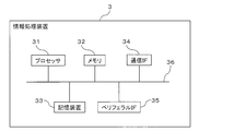
- FIG. 2 is a block diagram illustrating a configuration example of an information processing apparatus illustrated in FIG. 1.
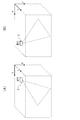
- (A) is a figure for demonstrating an example of the relationship between the gravity direction and radio wave irradiation surface when the sensor which concerns on one Embodiment is installed in the ceiling of indoor space
- (B) is one Embodiment. It is a figure for demonstrating an example of the relationship between the gravity direction and radio wave irradiation surface at the time of the sensor which concerns on being installed in the bed.
- 2 is a flowchart for explaining an operation example (first embodiment) of the sensor system illustrated in FIG. 1; It is a figure which shows an example of the angle table used in order to determine the sensor installation angle which concerns on one Embodiment.
- (A) is a figure which shows typically a mode that the sensor was installed in the wall so that the radio wave irradiation surface of the sensor which concerns on one Embodiment may face diagonally downward toward the center of indoor space from the upper right side of a wall.
- (B) is a figure which shows typically a mode that the sensor was installed in the wall so that the radio wave irradiation surface of the sensor which concerns on one Embodiment may face diagonally downward toward the center of indoor space from the upper left side of a wall. is there. It is a figure which shows an example of the transmission power control table which concerns on one Embodiment.
- FIG. 6 is a flowchart for explaining an operation example (second embodiment) of the sensor system illustrated in FIG. 1; It is a flowchart for demonstrating the operation example (3rd Example) of the sensor system illustrated in FIG.
- FIG. 20 is a diagram for explaining threshold correction exemplified in FIG. 19.
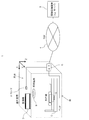
- FIG. 1 is a block diagram illustrating a configuration example of a sensor system according to an embodiment.
- the sensor system 1 illustrated in FIG. 1 may include a sensor 2 and an information processing device 3 exemplarily.
- Sensor 2 may be communicatively connected to network 4 via router 6, for example. Further, the information processing apparatus 3 may be connected to the network 4 so as to be able to communicate. Therefore, for example, the sensor 2 may be able to communicate with the information processing device 3 via the router 6 and the network 4. Communication between the sensor 2 and the information processing device 3 may be bidirectional communication.
- the sensor 2 illustratively transmits information obtained by the sensor 2 to the information processing device 3 by communication with the information processing device 3 or receives a control signal for the sensor 2 from the information processing device 3. Can be.
- the information obtained by the sensor 2 may be referred to as “sensor information”, “sensor data”, or “detection information” for convenience.
- the connection between the sensor 2 and the router 6 may be a wired connection or a wireless connection.
- the sensor 2 may be provided with a communication interface (IF) that supports communication by one or both of wired and wireless.
- IF communication interface
- WiFi Wireless Fidelity
- Bluetooth registered trademark
- the network 4 may correspond to, for example, a WAN (Wide Area Network), a LAN (Local Area Network), or the Internet.
- the network 4 may include a radio access network.
- the router 6 may be able to communicate with the information processing apparatus 3 by connecting to the wireless access network through a wireless IF.
- the information processing apparatus 3 can communicate with the sensor 2 via the network 4 and the router 6 as described above.
- the information processing device 3 may control the operation of the sensor 2 based on information received from the sensor 2 or may control the environment of a space that includes a part or all of the sensing range of the sensor 2. it can.
- the space may be an indoor (or indoor) space.
- the sensor 2 may be installed (may be referred to as “arrangement”) in an indoor space such as a bedroom.
- Controlling the operation of the sensor 2 may illustratively include controlling the transmission power of the radio wave transmitted by the sensor 2 as will be described later. Therefore, the information processing device 3 may be regarded as an example of a “sensor control device”.
- controlling the environment of the indoor space may include, for example, controlling the indoor space to a comfortable environment for the user in the indoor space.
- the information processing device 3 controls the temperature, the air volume, the wind direction, the dimming of the lighting fixture 8, and the like installed in the indoor space by communication via the network 4 based on the sensor information.
- the control may illustratively be a control that helps a user sleep. Such control may be referred to as “quiet sleep control” for convenience.
- the air conditioner 7 and the lighting fixture 8 are connected to the router 6 in a wired or wireless manner, like the sensor 2, so that the router 6 and the network 4 are connected. It may be possible to communicate with the information processing apparatus 3 via the network.
- the information processing apparatus 3 may be configured using one or a plurality of servers, for example.
- the environment of the sensor 2 and the indoor space may be controlled by one server, or may be controlled in a distributed manner by a plurality of servers.
- the server may correspond to a cloud server provided in a cloud data center.
- the air conditioner 7 and the lighting fixture 8 may be for home use or business use.
- the home air conditioner 7 and the lighting fixture 8 are examples of so-called “home appliances”, and “home appliances” capable of communicating with the network 4 may be referred to as “information home appliances”.
- the information processing apparatus 3 can receive (and may be referred to as “acquisition”) the sensor data of the sensor 2 via the network 4 and process it. Therefore, the information processing device 3 may be referred to as a sensor data processing device 3.
- the information processing device 3 can determine the state of the user's body movement, heartbeat, respiration, etc. (may be referred to as “estimation”). Based on the estimation result, the information processing apparatus 3 may control the indoor environment as described above.
- the sensor 2 is capable of sensing the biological information of the user in the indoor space without contact.
- the user in the indoor space is an example of a sensing target by the sensor 2.
- the “user” may be referred to as “observed person” or “subject” by the sensor 2.
- the “biological information” may be referred to as “vital information”.
- “Sensing” may be rephrased as “detection” or “measurement”.
- a non-limiting example of vital information is information indicating a user's heartbeat, breathing, and body movement.
- the “body movement” of the user may be abbreviated as “body movement” for convenience.
- the “body movement” is not limited to the movement of the user during the activity, and may include a movement of the body in accordance with a change in heartbeat and breathing at the time of rest such as sleep of the user. Based on the vital information, for example, it is possible to detect, determine, or estimate the sleep state of whether the user is sleeping or awake.
- the sensor 2 may be referred to as “non-contact type body motion sensor 2” or “non-contact type sleep sensor 2” for convenience.
- the determination of the sleep state based on vital information may be abbreviated as “sleep determination” for convenience. An example of the sleep determination method will be described later.
- “Sensor information” transmitted from the sensor 2 to the information processing device 3 may include one or both of a measurement value as a sensing result and information generated by the sensor 2 based on the measurement value.
- the sensor 2 may include a radio wave sensor 21 and an inertial sensor 22 as will be described later with reference to FIGS. 4 and 5.
- the sensor 2 including the radio wave sensor 21 and the inertial sensor 22 may be referred to as “sensor unit 2” for convenience.
- the radio wave sensor 21 irradiates a sensing target with radio waves such as microwaves, and can detect the “movement” of the sensing target in a non-contact manner based on a change in a reflected wave received by being reflected by the sensing target.
- the radio wave sensor 21 may be referred to as a “Doppler sensor 21”.
- the reflected wave changes due to the Doppler effect.
- the change in the reflected wave can be viewed as a change in one or both of the amplitude and frequency of the reflected wave.
- the sensing object is illustratively a living body such as a human body
- vital information can be sensed because the distance between the radio wave sensor 21 and the sensing object changes according to the “movement” of the living body.
- the “movement” of the living body (which may be referred to as “position change”) is not limited to the physical movement during the activity of the living body, but the heartbeat and breathing at rest such as sleeping of the living body. Movement of the biological surface (eg, skin) in response to
- the movement of the living body surface occurs according to the movement of the organ of the living body.
- the skin moves according to the heartbeat.
- the skin moves according to the expansion and contraction of the lungs accompanying breathing.
- the reflected wave of the microwave irradiated by the radio wave sensor 21 changes due to the Doppler effect. Based on the change, for example, physical movement, heartbeat, respiration, and the like are indicated. It is possible to sense vital information.
- the radio wave sensor 21 Based on the vital information sensed by the radio wave sensor 21, it is possible to detect, determine, or estimate the sleep state of the living body in a non-contact manner, for example, whether the living body is sleeping or awake. .
- the senor 2 may be disposed inside or outside the ceiling or wall of the indoor space, the lighting fixture 8 attached to the ceiling, or inside or outside the air conditioner 7 attached to the wall. It may be arranged on furniture or bedding (for example, bed 5) installed in the room. As a non-limiting example, FIG. 1 illustrates that the sensor 2 may be disposed on the ceiling or the bed 5.
- the mode in which the sensor 2 is arranged on the ceiling is an example of the mode in which the sensor 2 is arranged above the space with the radio wave transmission side of the radio wave sensor 21 facing the space.
- the mode in which the sensor 2 is disposed on the bed 5 is an example of a mode in which the sensor 2 is disposed below the space with the radio wave transmission side of the radio wave sensor 21 facing upward.
- the mode in which the sensor 2 is arranged on the wall is an example of a mode in which the sensor 2 is arranged on the side of the space with the radio wave transmission side of the radio wave sensor 21 facing the side of the space.
- the senor 2 may be arranged in association with the user.
- the sensor 2 may be attached to the bed 5 such that the sensing range includes a part or all of the sleeping area that is assumed to be occupied by the user at bedtime.
- the senor 2 may be attached at a position where the directivity of the transmission radio wave is formed with respect to the sleeping area of the user and the radio wave can be emitted toward the user.
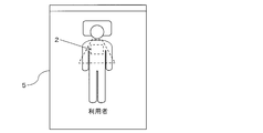
- an attachment position (sometimes referred to as a “sensor attachment position” for convenience), as schematically illustrated in FIGS. 2 and 3, the back side of the bed 5, for example, the back side of the mattress 52. The position where the user can radiate radio waves is given.
- the senor 2 directs the transmission radio wave in the area corresponding to the sleeping area of the user on the floor board (also referred to as “bottom board”) 53 (see FIG. 3) of the bed 5 on which the mattress 52 is placed. It may be attached so that the sex faces upward.
- the floor board also referred to as “bottom board” 53 (see FIG. 3) of the bed 5 on which the mattress 52 is placed. It may be attached so that the sex faces upward.
- the sensing range of the sensor 2 may be set so as to include the chest of the user, as schematically illustrated in FIGS. This setting facilitates measurement of the user's heart rate and respiration.
- the sensing range of the sensor 2 can be adjusted by controlling the transmission power of the radio wave transmitted by the radio wave sensor 21, as will be described later.
- a region including at least the chest of the user is included in the sensing range so that the user's heartbeat and respiration can be easily measured. Easy to adjust.
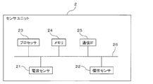
- the sensor 2 may include, for example, a radio wave sensor 21, an inertial sensor 22, a processor 23, a memory 24, and a communication IF 25.
- the radio wave sensor 21, the inertial sensor 22, the processor 23, the memory 24, and the communication IF 25 are exemplarily connected to each other via a communication bus 26 so that communication via the processor 23 is possible. Good.
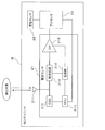
- the radio wave sensor 21 may be the Doppler sensor 21 and illustratively generates a beat signal by phase detection of the radio wave transmitted to the space and the reflected wave of the transmission radio wave.
- a beat signal may be given to the processor 23 as an output signal of the radio wave sensor 21.
- the radio wave sensor 21 includes an antenna 211, a local oscillator (Oscillator, OSC) 212, an MCU (Micro Control Unit) 213, a detection circuit 214, an operational amplifier (OP) 215, and a power source (or power source). Circuit) 216.
- OSC local oscillator
- MCU Micro Control Unit
- OP operational amplifier
- Circuit 216.
- the antenna 211 transmits the radio wave having the oscillation frequency generated by the OSC 212 to the space, and receives the radio wave (reflected wave) reflected by the user located in the space.
- the antenna 211 is shared for transmission and reception, but may be individual for transmission and reception.
- the OSC 212 illustratively oscillates according to the control of the MCU 213 and outputs a signal of a predetermined frequency (may be referred to as a “local signal” for convenience).
- the local signal is transmitted as a transmission radio wave from the antenna 211 and input to the detection circuit 214.
- the oscillation frequency of the OSC 212 (in other words, the frequency of the radio wave transmitted by the radio wave sensor 21) may be, for example, a frequency in the microwave band.
- the microwave band may be a 2.4 GHz band or a 24 GHz band.
- These frequency bands are examples of frequency bands that are allowed to be used indoors by the Japanese Radio Law.
- a frequency band not subject to regulations of the Radio Law may be used for the transmission radio wave of the radio sensor 21.
- the MCU 213 exemplarily controls the oscillation operation of the OSC 212 according to the control of the processor 23.
- the detection circuit 214 detects the phase of the reflected wave received by the antenna 211 and the local signal from the OSC 212 (in other words, the transmission radio wave) and outputs a beat signal.
- the detection circuit 214 may be replaced with a mixer that mixes the transmission radio wave and the reflected wave. Mixing by the mixer may be regarded as equivalent to phase detection.
- an amplitude change and a frequency change appear due to the Doppler effect in accordance with physical changes such as a user's heartbeat, respiration, and body movement.
- the beat signal includes information indicating physical changes such as a user's heartbeat, respiration, and body movement.
- the operational amplifier 215 amplifies the beat signal output from the detection circuit 214.
- the amplified beat signal is input to the processor 23.
- the power supply unit 216 illustratively supplies drive power to the MCU 213, the detection circuit 214, and the operational amplifier 215.
- the inertial sensor 22 may detect, for example, the orientation of the sensor 2 with respect to the direction of gravity (which may be referred to as “attachment angle” or “installation angle”).
- the inertial sensor 22 may be an acceleration sensor or a gyroscope.
- the acceleration sensor for example, any one of a piezoelectric sensor and a capacitance sensor may be applied.
- the gyroscope any of a rotary machine (coma) type, an optical type, and a vibration type sensor may be applied.
- the inertial sensor 22 may have one or a plurality of detection axes.
- the gravity component in the direction along the detection axis may be detected as “acceleration”, for example.
- At least one detection axis of the inertial sensor 22 may be oriented in the direction of directivity of radio waves transmitted from the radio wave sensor 21 to the outside of the sensor unit 2 (which may be referred to as “radio wave irradiation direction” for convenience). .
- At least one detection axis of the inertial sensor 22 may be oriented in a direction along the direction from the radio wave sensor 21 that is a radio wave transmission source toward the radio wave irradiation surface or the radio wave irradiation side of the sensor unit 2.
- the detection signal of the inertial sensor 22 may be input to the processor 23.
- the processor 23 is an example of an arithmetic processing device having arithmetic processing capability.
- the arithmetic processing apparatus may be referred to as an arithmetic processing device or an arithmetic processing circuit.
- an integrated circuit Integrated Circuit, IC
- MPU Micro Processing Unit
- DSP Digital Signal Processor
- the “processor” may be referred to as a “control unit” or a “computer”.
- the processor 23 can detect the vital information of the user in the indoor space based on the detection signal of the radio wave sensor 21, and can determine the sleep state of the user based on the vital information.
- the detection signal of the inertial sensor 22 may be used for transmission power control of the radio wave transmitted by the radio wave sensor 21.
- the detection signal of the inertial sensor 22 is a correction of the detection signal of the radio wave sensor 21 or information obtained based on the detection signal (may be collectively referred to as “correction of sensor information” for convenience) or body movement. You may use for the correction
- both the detection signal of the radio wave sensor 21 and the detection signal of the inertial sensor 22 may be referred to as “detection value” or “output value”.
- the detection value of the radio wave sensor 21 may be referred to as “radio wave sensor value” for convenience
- the detection value of the inertial sensor 22 may be referred to as “inertia sensor value” for convenience.
- part or all of the above-described transmission power control of the radio wave sensor 21, detection of vital information, determination of a user's sleep state, correction of sensor information, and correction of a threshold value are exemplarily performed in the sensor unit 2. Or may be implemented in the information processing apparatus 3.
- the memory 24 is an example of a storage medium, and may be a RAM (Random Access Memory), a flash memory, or the like.
- the memory 24 may store programs and data used for the processor 23 to read and operate.
- the “program” may be referred to as “software” or “application”.
- the “data” may include data generated according to the operation of the processor 23.
- the communication IF 25 is an example of a communication unit provided in the sensor unit 2.
- the communication IF 25 is connected to the router 6 (see FIG. 1) and enables communication with the information processing apparatus 3 via the network 4.
- the communication IF 25 may transmit information obtained based on one or both of the detection signals of the radio wave sensor 21 and the inertial sensor 22 or one or both of the detection signals to the information processing apparatus 3.
- the sensor information transmitted from the sensor 2 to the information processing device 3 may include one or both of the measured values obtained by the radio wave sensor 21 and the inertial sensor 22, or one or both of the measured values. Information obtained on the basis of may be included.
- the sensor unit 2 may be supplied with electric power from the outside.
- the sensor unit 2 may be supplied with electric power from an alternating current (AC) power source provided in an indoor space, or may be supplied with electric power from a power source provided in the air conditioner 7, the lighting fixture 8, or the bed 5. May be.
- the power source for the sensor unit 2 may be shared with the power source for the air conditioner 7, the lighting fixture 8, and the bed 5.
- the sensor unit 2 is capable of sensing.
- the sensor unit 2 can operate as the sensor unit 2 alone even when the power for the air conditioner 7, the lighting fixture 8, and the bed 5 is not supplied, and thus can be used as a “watch function”.
- a universal serial bus may be applied to the connection between the sensor unit 2 and the power supply for the air conditioner 7, the lighting fixture 8, and the bed 5.
- USB universal serial bus
- the sensor unit 2 may be detachably connected to the USB port with a USB cable.
- the information processing apparatus 3 may include a processor 31, a memory 32, a storage device 33, a communication interface (IF) 34, and a peripheral IF 35, for example.
- the processor 31, the memory 32, the storage device 33, the communication IF 34, and the peripheral IF 35 may be communicatively connected to each other via the processor 31 by a communication bus 36, for example.
- the processor 31 is an example of an arithmetic processing device having arithmetic processing capability.
- the arithmetic processing apparatus may be referred to as an arithmetic processing device or an arithmetic processing circuit.
- an IC or DSP such as a CPU or MPU may be applied to the processor 31 which is an example of an arithmetic processing unit.
- the processor 31 is an example of a control unit (or computer) that controls the overall operation of the information processing apparatus 3 exemplarily. Control by the processor 31 may include controlling communication via the network 4. For example, the air conditioner 7 and the lighting fixture 8 may be remotely controlled via the network 4 by controlling the communication.
- the processor 31 may perform part or all of the above-described processing that may be performed by the processor 23 of the sensor 2 based on the sensor information of the sensor 2 received by the communication IF 34.
- Examples of the processing described above are transmission power control of the radio wave sensor 21, correction of sensor information, correction of a threshold value used for body movement detection and sleep determination, and the like.
- the processor 31 may generate a control signal for the sensor 2 exemplarily.
- the processor 31 may generate a control signal for controlling the transmission power of the radio wave transmitted by the radio wave sensor 21 based on the detection information of the inertial sensor 22 acquired from the sensor 2.
- the processor 31 may generate a control signal for controlling the environment of the space where the sensor 2 is installed, for example, a control signal for controlling the operation of the air conditioner 7 or the lighting fixture 8.
- the said control signal may be produced
- the control signal generated by the processor 31 may be transmitted to the sensor 2, the air conditioner 7, the lighting fixture 8, and the like via the communication IF 34, for example.
- the memory 32 is an example of a storage medium, and may be a RAM, a flash memory, or the like.
- the memory 32 may store a program and data used for the processor 31 to read and operate.
- the storage device 33 may store various data and programs.
- the storage device 33 may be a hard disk drive (HDD), a solid state drive (SSD), a flash memory, or the like.
- the data stored in the storage device 33 exemplarily includes the sensor information of the sensor 2, the vital information obtained based on the sensor information, and the sleep state estimated based on the vital information received by the communication IF 34.
- a determination result or the like may be included.
- the data stored in the storage device 33 may be appropriately converted into a database (DB).
- DB data may be referred to as “cloud data” or “big data”.
- the storage device 33 and the memory 32 may be collectively referred to as “storage unit”.
- the program stored in the storage device 33 may include a program for executing processing to be described later with reference to FIGS.
- the program for executing the processing described later in FIG. 8 may be referred to as a “sensor control program” for convenience.
- a program for executing the processing described later with reference to FIGS. 18 and 19 may be referred to as a “sensor data processing program” for convenience.
- All or part of the program code constituting the program may be stored in the storage unit, or may be described as part of the operating system (OS).
- OS operating system
- the program and data may be provided in a form recorded on a computer-readable recording medium.
- the recording medium include a flexible disk, CD-ROM, CD-R, CD-RW, MO, DVD, Blu-ray disk, portable hard disk, and the like.
- a semiconductor memory such as a USB (UniversalUniversSerial Bus) memory is also an example of a recording medium.
- the program and data may be provided (downloaded) to the information processing apparatus 3 via the network 4 from a server or the like.
- a program and data may be provided to the information processing device 3 through the communication IF 34.
- the program and data may be input to the information processing apparatus 3 from an input device described later connected to the peripheral IF 35.
- the communication IF 34 is an example of a communication unit provided in the information processing apparatus 3 and is illustratively connected to the network 4 to enable communication via the network 4.
- the communication IF 34 is an example of a receiving unit (may be referred to as an “acquisition unit”) that receives information transmitted from the sensor 2 to the information processing device 3 when attention is focused on reception processing.
- the communication IF 34 is an example of a transmission unit that transmits the control signal generated by the processor 31 to the sensor 2, the air conditioner 7, and the lighting fixture 8.
- an Ethernet (registered trademark) card may be applied to the communication IF 34.
- the peripheral IF 35 is an interface for connecting peripheral devices to the information processing apparatus 3 exemplarily.
- Peripheral devices may include an input device for inputting information to the information processing device 3 and an output device for outputting information generated by the information processing device 3.
- the input device may include a keyboard, a mouse, a touch panel, and the like.
- the output device may include a display, a printer, and the like.
- the average distance between the sensor 2 and the user may differ depending on the arrangement position.
- the average distance between the sensor 2 and the user is greater in the ceiling installation than in the bed installation. It can be said.
- the radio wave transmitted by the radio wave sensor 21 is attenuated as the propagation distance becomes longer. Therefore, unless the processing for the transmission power and the received wave of the radio wave sensor 21 is appropriately selected according to the distance between the sensor 2 and the user, the user's The body motion detection accuracy, and thus the user's sleep determination accuracy, may be reduced.
- the detection signal level of the radio wave sensor 21 may not reach a level sufficient to detect the user's body movement. There is.
- the received wave responds to an object or a person's movement that is different from the body motion component of the user who is the sensing target.
- the component is easily mixed into the detection signal of the radio wave sensor 21.
- the received power of the reflected wave becomes too high, and the detection signal of the radio wave sensor 21 is saturated, and there is a possibility that the user's body motion component cannot be detected.
- the transmission power and detection signal level of the radio wave sensor 21 can be regarded as examples of parameters that determine the detection sensitivity of the user's body motion component. If the transmission power or the detection signal level of the radio wave sensor 21 is excessive or insufficient with respect to the distance between the sensor 2 and the user, the detection sensitivity of the body motion component may be excessive or insufficient. As a result, the user's body motion detection accuracy, and thus the user's sleep determination accuracy, may be reduced.
- body motion detection or sleep determination is performed by comparing the detection signal of the radio wave sensor 21 (or information obtained based on the detection signal) with a threshold value, an assumed distance between the sensor 2 and the user If the threshold value corresponding to is not set, the accuracy of body movement detection and sleep determination may be reduced.
- the threshold used for body motion detection and sleep determination can be regarded as another example of a parameter that determines the detection sensitivity of the user's body motion component. If the threshold according to the distance between the sensor 2 and the user is not set appropriately, the body motion component and the sensitivity of sleep determination may be excessive or insufficient. As a result, the user's body motion detection accuracy, and thus the user's sleep determination accuracy, may be reduced.
- a sensor that is prepared by installing in advance a sensor 2 that adjusts the transmission power and detection signal level of the radio wave sensor 21 according to the assumed distance between the sensor 2 and the user, for example, according to the installation location of the sensor 2. If 2 is properly used, excess or deficiency in detection sensitivity may be avoided.
- a sensor 2 adjusted for ceiling installation and a sensor 2 adjusted for bed installation are prepared, the ceiling installation sensor 2 is installed on the ceiling, and the bed installation sensor 2 is installed on the bed 5. Install.
- the transmission power and the detection signal level of the radio wave sensor 21 can be adjusted, for example, when the sensor 2 is installed, one sensor 2 can be shared by a plurality of installation locations. Take it. In some cases, the sensor 2 must be provided with a switch for switching the transmission power and the detection signal level according to the installation location of the sensor 2.
- the sensor 2 is a sensor 2 for each installation location or the sensor 2 is not limited to the installation location, the sensor (for example, either the sensor 2 or the information processing device 3) may be used for processing or analyzing sensor information. The trouble of registering information or the like that can identify the installation location of 2 may occur.
- the detection signal level of the radio wave sensor 21 and the body motion detection threshold value can be corrected according to the assumed distance between the sensor 2 and the user, in other words, according to the installation location of the sensor 2. It is to make it.
- the degree of freedom and flexibility may be limited with respect to the setting location of the sensor 2 and the information processing device 3 and the layout change of the indoor space, for example, in relation to the installation location of the sensor 2.
- the installation location of the sensor 2 is detected, determined, or estimated using the inertial sensor 22 provided in the sensor 2, and the detection sensitivity of the radio wave sensor 21 is controlled according to the result.
- the body motion detection accuracy of the user, and thus the sleep determination accuracy is improved.
- the installation location of the sensor 2 may be detected, determined, or estimated based on the orientation of the sensor 2 with respect to the direction of gravity detected by the inertial sensor 22 as an example.
- the inertial sensor 22 when at least one detection axis of the inertial sensor 22 is oriented in the direction along the radio wave irradiation direction of the radio wave sensor 21, and the sensor 2 is installed on the ceiling, it is installed on the bed 5. Assuming that it is installed on a wall.
- the installation on the ceiling is an example of an aspect in which the sensor 2 is installed above the indoor space to be sensed by the sensor 2, and the installation on the bed 5 is the sensor 2 installed below the indoor space.
- Installation on the wall is an example of a mode in which the sensor 2 is installed on the side of the indoor space.
- the radio wave irradiation surface by the radio wave sensor 21 of the sensor 2 is below the indoor space (for example, in the positive direction of the Z axis).
- the direction of gravity detected by the inertial sensor 22 is directed to the same side as the side where the radio wave is transmitted from the sensor 2 by the radio wave sensor 21.
- the direction of gravity detected by the inertial sensor 22 is shifted from or orthogonal to the direction in which radio waves are transmitted from the radio wave sensor 21 in the sensor 2. Facing the direction.
- Control of detection sensitivity by the radio wave sensor 21 based on the determination result as described above may include controlling or correcting a parameter that changes the detection sensitivity as described above.
- the detection sensitivity of the radio wave sensor 21 may be controlled by controlling or correcting at least one of the transmission power of the radio wave sensor 21, the detection signal level of the radio wave sensor 21, and the threshold used for body movement detection and sleep determination. .
- correcting the detection signal level of the radio wave sensor 21 and correcting the threshold value are both examples of changing the process of the reflected wave of the transmission radio wave by the radio wave sensor 21. .
- the information processing device 3 can change the processing of the reflected wave of the transmission radio wave by the radio wave sensor 21 according to the direction of gravity detected by the inertial sensor 22.
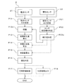
- FIG. 8 is a flowchart illustrating an operation example of the sensor system 1 according to the first embodiment.
- the flowchart illustrated in FIG. 8 may be executed by the information processing apparatus 3 (for example, the processor 31) exemplarily.
- the information processing device 3 receives the sensor value of the radio wave sensor 21 from the sensor 2 (processing P11). Further, the information processing device 3 receives the inertial sensor value from the inertial sensor 22 (Process P21).
- the information processing device 3 may determine the installation angle of the sensor 2 based on the inertial sensor value (processing P22). For the determination, for example, an installation location classification table 321 shown in FIG. 9 may be used. For example, the installation location classification table 321 may be stored in the memory 32 of the information processing apparatus 3.
- the installation location classification table 321 is an example of information that classifies the installation location of the sensor 2 by a combination of detection values for each detection axis of the inertial sensor 22.
- the installation location classification table 321 indicates whether the sensor 2 is installed above (for example, the ceiling), below (for example, the bed 5), or side (for example, the wall) of the indoor space.
- the inertial sensor 22 is a three-axis sensor having three detection axes X, Y, and Z orthogonal to each other, and accelerations Ax, Ay in directions along the individual detection axes X, Y, and Z And Az are detected as inertial sensor values, respectively.
- the ceiling and the floor are regarded as planes parallel to the XY plane.
- the wall can be regarded as a plane parallel to the XZ plane or the YZ plane.
- the processor 31 which is an example of the control unit in the information processing device 3, It can be determined that it is installed on the ceiling.
- the processor 31 can determine that the sensor 2 is installed on the bed 5.
- the inertial sensor value Ax takes a negative value
- the gravity direction detected based on the inertial sensor value is neither the same side as the side on which the radio wave is transmitted from the sensor 2 or the opposite side. 31 may determine that the sensor 2 is installed on the wall.
- the information processing apparatus 3 refers to the installation location classification table 321 based on the inertial sensor values (Ax, Ay, Az), so that the sensor 2 has the ceiling, the bed 5, and the wall of the indoor space. It can be easily determined and identified at low load whether it is installed (right side or left side).
- the information processing device 3 uses the radio wave so that the transmission power of the radio wave transmitted by the radio wave sensor 21 becomes an appropriate power (in other words, detection sensitivity) according to the installation location of the sensor 2.
- the sensor 21 may be controlled (processing P23 and P24 in FIG. 8).
- a lateral distance for example, a distance between opposing walls
- a vertical distance in other words, a distance between a ceiling and a floor. Therefore, when the transmission power of the radio wave sensor 21 when the sensor 2 is installed on the side of the indoor space is the reference power, the transmission power of the radio wave sensor 21 when the sensor 2 is installed on the ceiling is smaller than the reference power. It's okay.
- the transmission power of the radio wave sensor 21 when the sensor 2 is installed on the bed 5 may be smaller than the transmission power when the sensor 2 is installed on the ceiling.
- the processor 31 increases the transmission power of the radio wave sensor 21 in comparison with the case where the sensor 2 is installed on the bed 5 in response to the determination that the sensor 2 is installed on the ceiling located above the indoor space. Control may be performed. By this control, it is possible to suppress or avoid that the amount of body movement of the user is under-detected or difficult to detect.
- the processor 31 determines the transmission power of the radio wave sensor 21 as compared with the case where the sensor 2 is installed on the ceiling in response to the determination that the sensor 2 is installed on the bed 5 positioned below the indoor space. Control to make it smaller may be performed. By this control, it is possible to suppress or avoid that the amount of body movement of the user is excessively detected or that the detection signal of the radio wave sensor 21 is saturated and difficult to detect.
- the processor 31 determines the transmission power of the radio wave sensor 21 in response to the determination that the sensor 2 is installed on the side wall of the indoor space, compared to the case where the sensor 2 is installed on the bed 5 and the ceiling. You may perform control to enlarge. By this control, it is possible to suppress or avoid that the amount of body movement of the user is under-detected or difficult to detect.
- the transmission power 21 can be represented by the transmission power control table 322 in FIG.
- the information processing apparatus 3 may calculate the correction value of the transmission power of the radio wave sensor 21 according to the installation location of the sensor 2 based on the transmission power control table 322 (process P23 in FIG. 8). Then, the information processing device 3 may generate a transmission power control signal of the radio wave sensor 21 according to the calculated correction value and transmit it to the sensor 2 (processing P24).
- the transmission power control signal is received by, for example, the processor 23 of the sensor 2 (see FIG. 6), and the processor 23 controls the MCU 213 of the radio wave sensor 21 according to the transmission power control signal to Control power.
- the transmission power of the radio wave transmitted from the radio wave sensor 21 is controlled to a power suitable for the installation location of the sensor 2, and the detection sensitivity of the radio wave sensor 21 is controlled to a sensitivity suitable for the installation location of the sensor 2.
- the information processing device 3 acquires the measurement value of the inertial sensor 22 from the sensor 2 as an example of detection information of the inertial sensor 22.
- the information processing device 3 may acquire information obtained based on the measurement value of the inertial sensor 22, for example, information indicating the direction of gravity or information indicating the location of the sensor 2 from the sensor 2. Good.
- the sensor 2 may transmit the measurement value itself of the inertial sensor 22 to the information processing device 3, or information obtained based on the measurement value.
- Information that can be specified by the device 3 may be transmitted to the information processing device 3.
- the information processing device 3 can control the transmission power of the radio wave sensor 21 according to the installation location of the sensor 2 as described above based on the information obtained from the sensor 2 and capable of specifying the installation location of the sensor 2. .
- the information processing apparatus 3 uses the radio wave sensor value received from the sensor 2 as a user.
- the body movement amount detection and sleep state determination may be performed.
- the information processing device 3 appropriately amplifies the radio wave sensor value received from the sensor 2 (processing P12), calculates the amplitude change amount of the radio wave sensor value (processing P13), The “wavelength” may be calculated (processing P14). Further, the information processing apparatus 3 may calculate the “body movement amount” of the user based on the “wavelength during extension” (processing P15).
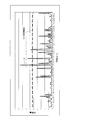
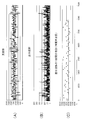
- FIG. 12 is a diagram illustrating an example of a temporal change in body movement as an example of vital information obtained based on the radio wave sensor value.
- a signal waveform indicated by a dotted line A shows an example of a temporal change in the amount of body movement. Good).
- the amount of body movement exceeds the determination threshold, it may be determined that the user is awake, and if the amount of body movement is less than the determination threshold, it may be determined that the user is sleeping. .
- the amount of body movement can be grasped as a time change of the radio wave sensor value. For example, when a user who is a sensing target is awake and active, the body movement of the sensing target appears as a change in amplitude value and frequency in the radio wave sensor value. For example, the amplitude value and frequency of the radio wave sensor value tend to increase as the amount of body movement of the user increases.
- the body movement of the user is dominated by changes in heart rate and breathing. Therefore, it may be considered that the amplitude value of the radio wave sensor value does not change or can be ignored even if there is a change.
- the body movement caused by changes in heart rate and respiration appears as a frequency change of the radio wave sensor value.
- the frequency of the radio wave sensor value tends to increase as the heart rate and the respiration rate increase.
- the amount of body movement can be detected based on the change in the amplitude value and frequency of the radio wave sensor value.
- Changes in the amplitude value and frequency of the radio wave sensor value can be grasped as, for example, a change in length when the signal waveform (see dotted line A) shown in FIG. 12 is straightened in the time domain.
- the “wavelength during extension” is a different concept from the normal “wavelength”.
- the “stretching wavelength” may be regarded as corresponding to the length of the locus drawn by the radio wave sensor value in the time domain in a certain unit time.
- the unit time may be a “second” unit or a “minute” unit.
- FIG. 13 schematically illustrates the concept of “wavelength during extension”.
- the horizontal axis in FIG. 13 indicates time (t), and the vertical axis in FIG. 13 indicates a radio wave sensor value (for example, voltage [V]).
- a radio wave sensor value for example, voltage [V]
- a signal waveform indicated by a dotted line A schematically represents a time change of the radio wave sensor value when the user to be sensed is sleeping.
- a signal waveform indicated by a solid line B schematically represents a time change of the radio wave sensor value when the sensing target user is awake and active.
- the “wavelength during extension” corresponds to the length when the signal waveform per unit time ( ⁇ T) indicated by the dotted line A and the solid line B is linearly extended in the time direction. To do.
- the “wavelength during extension” is illustratively stored in the memory 32 (see FIG. 6) sequentially, for example, at a certain period (which may be referred to as “sampling period”). It can be calculated by adding the amount of change in amplitude value over a unit time.
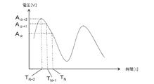
- the horizontal axis in FIG. 14 represents time (t), and the vertical axis in FIG. 14 represents a radio wave sensor value (for example, voltage [V] corresponding to an amplitude value).
- the Doppler sensor values are “A ⁇ + 2 ”, “A ⁇ + 1 ”, and “ A ⁇ ”.
- N is an integer representing a timing label.
- A is a real number that the voltage value [V] can take, and “ ⁇ ” is an integer representing a label of the voltage value.
- the sampling timing interval may be constant or different.
- the information processing apparatus 3 exemplarily determines the amplitude change amount between the sampling timings based on the amplitude value (voltage value) obtained at each sampling timing.
- the processor 31 of the information processing device 3 may obtain a difference between amplitude values at adjacent sampling timings as an amplitude change amount between the sampling timings (corresponding to the process P13 in FIG. 8).
- the processor 31 repeatedly performs such an operation over the number of samplings per unit time, and the obtained amplitude change amount is expressed as
- the “wavelength during extension” can be calculated (corresponding to process P14 in FIG. 8).
- the radio wave sensor value when the radio wave sensor value is represented by a voltage value [V], the unit of “wavelength during extension” may be represented by, for example, “voltage / time” (V / min). .
- FIG. 15 (A) to FIG. 15 (C) show an example of extension wavelength calculation processing.
- 15A shows an example of the original waveform of the radio wave sensor value
- FIG. 15B shows an example of the difference waveform
- FIG. 15C shows the difference waveform for a predetermined time (for example, 1 second). ) Shows an example of the summed value over.
- the differential waveform illustrated in FIG. 15B represents an amplitude change amount for each predetermined minute time with respect to the original waveform illustrated in FIG. 15A, and is illustratively a differential waveform calculated at a sampling period of 1 kHz. It is. Therefore, the amplitude change amount illustratively represents an amplitude change amount every 1/1000 second.
- the difference waveform may be summed every second in the period ⁇ T illustrated in FIG.
- the amplitude change amount may be summed every 1000 in the period ⁇ T.
- the extension wavelength in the period ⁇ T is calculated.
- the “wavelength during extension” may be time averaged over a predetermined time. For example, the average of 60 “wavelengths during extension” obtained per minute with a unit time of 1 second may be taken.
- the “wavelength during extension” may be calculated as follows.
- FIG. 16 shows an example in which the “wavelength during extension” of the curve AB is calculated.
- AB is divided into n minute sections, each minute section is approximated by a line segment, and the sum Sn of the lengths is expressed by the following formula 1.
- Equation 2 the minute displacement in the x direction in the minute section is ⁇ xk and the minute displacement in the y direction is ⁇ yk
- Equation 3 when the number n of minute sections in Equation 2 is increased infinitely, the sum Sn approaches the length L of the curve AB.
- Equation 3 assuming that the x-direction is the time axis and the sampling period of the radio wave sensor value is constant (for example, 1 kHz), “x k ” is constant, and “y k ” has a radio wave sensor value (for example, By substituting (amplitude value), the “wavelength during extension” is calculated.
- the information processing apparatus 3 calculates the “body movement amount” of the user based on the above-mentioned “stretching wavelength” and sleeps the user based on the calculated “body movement amount”.
- the state may be determined (Process P16).
- AW2 expression For sleep determination, for example, an arithmetic expression called “AW2 expression” or “Cole expression” (may be referred to as “determination expression”) may be applied. For example, if the value calculated by the “AW2 formula” or “Cole formula” based on the “body movement amount” obtained over a certain determination time (for example, several minutes) is equal to or greater than a certain threshold value, “sleep” If it is less than the threshold, it may be determined as “wakefulness”.
- the information processing device 3 Based on the sleep determination result, the information processing device 3 generates, for example, a control signal for controlling the operation of the air conditioner 7, the dimming of the lighting fixture 8, and the like, and transmits the control signal to the air conditioning device 7 or the lighting fixture 8. Good (processing P17). Thereby, the indoor space can be controlled in a comfortable environment for the user.
- the result of the sleep determination by the information processing device 3 may be appropriately output to an output device such as a display or a printer (processing P18). Further, the extension wavelength calculated in process P14 and the amount of body movement calculated in process P15 may be appropriately output to an output device such as a display or a printer. In this case, the status of the calculation process of information used for sleep determination can be confirmed.
- the process P14 for calculating the extension wavelength may be optional as shown by a dotted line in FIG.
- the body movement amount may be calculated in process P15 without calculating the extension wavelength. This point may be the same in the second embodiment (FIG. 18) and the third embodiment (FIG. 19) described later.
- the transmission power of the radio wave sensor 21 provided in the sensor 2 is controlled according to the direction of gravity detected by the inertial sensor 22 provided in the sensor 2.
- the detection sensitivity of the radio wave sensor 21 can be optimized according to the installation location of the sensor 2.
- the sensor installer is allowed to install the sensor 2 in the sense of the installer without performing detailed adjustment work at the beginning of sensor installation.
- the installation location of the sensor 2 can be automatically recognized based on the inertial sensor value, for example, the labor of adding or registering information that can identify the installation location to the sensor 2 or the information processing device 3 is troublesome. Can be omitted. Further, it is possible to save the trouble of changing the analysis process and the analysis algorithm of the sensor information according to the installation location of the sensor 2.
- the installation location of the sensor 2 can be freely changed after installation, and the degree of freedom and flexibility of the initial setting of the sensor 2 and the layout change of the indoor space can be improved.
- the detection sensitivity of the radio wave sensor 21 is optimized according to the installation location of the sensor 2, it is possible to prevent the detection sensitivity from being excessive or insufficient, and the probability that erroneous detection of body motion detection or erroneous determination of sleep determination occurs. Can be reduced. Therefore, it is possible to improve the accuracy of user body motion detection and sleep determination.
- the transmission power of the radio wave sensor 21 is optimized according to the installation location, the power consumption efficiency of the sensor 2 can be improved.
- the accuracy of the user's body motion detection and sleep determination can be improved, for example, the accuracy of the environmental control of the indoor space using the result of the body motion detection and sleep determination can be improved, and the efficiency of the environmental control Can be achieved.
- the information processing device 3 adaptively controls the operation of the air conditioner 7 and the dimming of the lighting fixture 8 according to the results of body movement detection and sleep determination, so that the indoor space is comfortable for the user. Can be controlled to the environment. Therefore, the accuracy of the environmental control can be improved by improving the accuracy of the user's body motion detection and sleep determination.
- the installation location classification table 321 illustrated in FIG. 9 may be created based on the angle information of the inertial sensor 22 calculated from the inertial sensor value, in other words, the angle information of the sensor 2.
- the angle information of the inertial sensor 22 includes accelerations Ax, Ay, and Az obtained for the detection axes X, Y, and Z of the inertial sensor 22, respectively. Based on the above, it can be obtained by the following equations 4 to 6.
- the installation location classification table 321 can be created by associating the angle information obtained by the above equations 4 to 6 with the location where the sensor 2 is assumed to be installed in the indoor space.
- the transmission power of the radio wave sensor 21 may be controlled based on the angle information obtained by Equations 4 to 6 without using the installation location classification table 321.
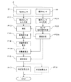
- the second embodiment is an operation example in which the detection signal level of the radio wave sensor 21 is corrected according to the direction of gravity detected by the inertial sensor 22.
- Correcting the detection signal level of the radio wave sensor 21 may be regarded as an example of changing the processing of the reflected wave of the transmission radio wave by the radio wave sensor 21.
- the processes P11, P13 to P17, P21, and P22 in FIG. 18 may be the same as the processes P11, P13 to P17, P21, and P22 described in FIG.
- the information processing device 3 causes the radio wave sensor value to have an appropriate detection signal level according to the installation location of the sensor 2 determined based on the inertial sensor value (in other words, detection sensitivity is obtained).
- the amplification factor of the radio wave sensor value in the process P12a may be controlled.
- the information processing apparatus 3 may determine a correction value for the amplification factor according to the installation location of the sensor 2. For example, the gain of the radio wave sensor value may be increased as the distance between the sensor 2 and the user is increased. Therefore, the correction value of the gain is determined in the same manner as the relationship in the table 322 illustrated in FIG. May be.
- the correction value of the amplification factor can be expressed by expressing the standard correction value when the wall of the sensor 2 is installed as “large”, the correction value when installing the ceiling as “medium”, and the correction value when installing the bed as “small”.
- the processing device 3 may correct the amplification factor of the current radio wave sensor value with a correction value corresponding to each installation location.
- the radio wave sensor value is based on information such as a table in which the angle information obtained by the above-described mathematical expressions 4 to 6 is associated with the place where the sensor 2 is assumed to be installed in the indoor space.
- the amplification factor may be corrected.
- the amplification factor of the radio wave sensor value may be corrected based on the angle information obtained by Equations 4-6.
- the amplification factor to be corrected may be the amplification factor of the operational amplifier 215 in the radio wave sensor 21 illustrated in FIG.
- the information processing apparatus 3 may generate a control signal including the correction value of the amplification factor (which may be referred to as “amplification factor control signal”) and transmit the control signal to the sensor 2 (for example, the processor 23).
- the correction target is not limited to the amplification factor, and as illustrated by the dotted arrow in FIG. 18, the “wavelength during extension” calculated in the process P14 may be used, or the process P15 based on the “wavelength during extension”.
- the correction values for “extension wavelength” and “body movement amount” may be determined in the same relationship as the magnitude relationship of the correction values for the amplification factor.
- the correction of the “wavelength at extension” can be realized by, for example, correcting the amplitude change amount of the candidate radio wave sensor value added to the “wavelength at extension”, so that the calculation amount by the processor 23 is suppressed. Can do.
- the detection value (or information obtained based on the detection value) of the radio wave sensor 21 is corrected in accordance with the direction of gravity detected by the inertial sensor 22.
- the detection sensitivity by 21 can be optimized according to the installation location of the sensor 2.
- the same effect as the first embodiment can be obtained, and in the second embodiment, unlike the first embodiment, it is not necessary to control the transmission power of the radio wave sensor 21.
- the delay of motion detection and sleep determination can be suppressed.
- the third example is an operation example in which the threshold of the amount of body movement (or sleep determination based on the amount of body movement) obtained based on the radio wave sensor value is corrected according to the direction of gravity detected by the inertial sensor 22.
- the threshold correction may be regarded as another example of changing the process for the reflected wave of the transmission radio wave by the radio wave sensor 21.
- the flowchart illustrated in FIG. 19 corresponds to a flowchart in which the processes P15 and P23 in FIG. 8 of the first embodiment are replaced with the processes P15b and P23b, respectively, and the process P24 in FIG. 8 is deleted.
- the processes P11 to P14, P16, P17, P21, and P22 in FIG. 19 may be the same as the processes P11 to P14, P16, P17, P21, and P22 described in FIG.
- the information processing apparatus 3 determines that the threshold used for the determination of the amount of body movement calculated in the process P15b is an appropriate value according to the installation location of the sensor 2 determined based on the inertial sensor value (in other words, detection
- the threshold value may be controlled so as to be (sensitivity).
- the information processing device 3 may determine a determination threshold for body movement amount according to the installation location of the sensor 2 determined based on the inertial sensor value. Correcting and determining the determination threshold may be exemplarily taken as controlling the reference value of the amount of body movement handled as a noise component.
- the body movement amount determination threshold may be corrected to be smaller. It may be considered that reducing the determination threshold corresponds to increasing the detection sensitivity of the body movement amount.
- the body movement amount determination threshold is “small” when the wall is installed, where the distance between the sensor 2 and the user is relatively large in the indoor space, “medium” when the ceiling is installed, and “large” when the bed is installed.
- the information processing apparatus 3 may determine and set a threshold value corresponding to each installation location as a determination threshold value for body movement based on the magnitude relationship.
- the calculated amount of body movement tends to be smaller.
- the information processing apparatus 3 corrects and sets the determination threshold C to a value smaller than that at the time of bed installation, for example, as schematically illustrated in FIG. May be high.
- the information processing apparatus 3 may correct and set the determination threshold C to a value larger than that at the time of ceiling installation to lower the detection sensitivity of the body movement amount.
- the information processing apparatus 3 sets the determination threshold C to a smaller value at the time of wall installation than at the time of ceiling installation. It may be corrected and set.
- the threshold value to be corrected according to the installation location of the sensor 2 is a threshold value (referred to as a reference value) for a signal level that does not have to be processed as a noise component in the process P12, as exemplified by a dotted arrow in FIG. It is also possible.
- the threshold value used for the sleep determination in the process P16 may be corrected according to the installation location of the sensor 2.
- the signal level threshold and the threshold used for sleep determination may be controlled to a smaller value in order to increase the detection sensitivity as the distance between the sensor 2 and the user increases.
- the information processing apparatus 3 has a small and small relationship when installing a wall, “medium” when installing a ceiling, and “large” when installing a bed.
- the threshold of the signal level and the threshold for sleep determination may be controlled accordingly.
- the determination threshold value is determined based on information such as a table in which the angle information obtained by the above-described mathematical expressions 4 to 6 is associated with the place where the sensor 2 is assumed to be installed in the indoor space. It may be corrected. Alternatively, the determination threshold value may be corrected based on the angle information obtained by Equations 4-6.
- the threshold value used for body movement detection and sleep determination based on the detection value (or information obtained based on the detection value) of the radio wave sensor 21 is corrected according to the direction of gravity detected by the inertial sensor 22. Therefore, the detection sensitivity of the radio wave sensor 21 can be optimized according to the installation location of the sensor 2.
- the third embodiment does not have to control the transmission power of the radio wave sensor 21 as in the second embodiment. Delay in detection and sleep determination can be suppressed.
- the first embodiment described above and one or both of the second embodiment and the third embodiment may be implemented in combination.
- the transmission power control of the radio wave sensor 21 according to the installation location of the sensor 2 and the process control of the reflected wave of the transmission radio wave by the radio wave sensor 21 may be performed in combination.
- the control of the detection sensitivity by the radio wave sensor 21 can be distributed to the transmission power control and the control of the process for the reflected wave, so that the control amount (in other words, the variable width) in each control can be set independently. It can be smaller than the control. Therefore, it is possible to reduce the control load and to reduce the performance required for the sensor 2 and the information processing device 3.
- FIGS. 8, 18 and 19 the mode in which the processing illustrated in FIGS. 8, 18 and 19 is performed by the information processing apparatus 3 (for example, the processor 31) has been described.
- part or all of the processing illustrated in FIGS. 8, 18 and 19 may be performed by the sensor 2 (for example, the processor 23).
- a program corresponding to the process performed by the sensor 2 may be stored in the memory 24 (see FIG. 5) of the sensor 2, for example.
- the determination process P22 illustrated in FIGS. 8, 18, and 19 may be performed by the processor 23 of the sensor 2.
- the processor 23 transmits information indicating the installation location of the sensor 2 determined based on the direction of gravity detected by the inertial sensor 2 from, for example, the communication IF 25 (see FIG. 5), which is an example of a communication unit, to the information processing apparatus 3. You may let me.
- the information indicating the installation location of the sensor 2 is, for example, whether the sensor 2 is disposed below the space (for example, the bed 5), disposed above the space (for example, the ceiling), or side of the space (for example, the wall). It may be information indicating whether or not it is arranged.
- the information processing device 3 controls the transmission power of the radio wave sensor 21 according to the installation location of the sensor 2 as described in the first embodiment. You can do it.
- the function addition of the information processing device 3 may be performed by modifying the program or data that the processor 31 of the information processing device 3 reads and operates. Updates are easily possible. Therefore, the sensor system 1 can be easily updated in an integrated manner by modifying the information processing apparatus 3 without modifying the sensor 2.
- the sleep determination of the user in the indoor space has been described. However, based on the radio wave sensor value, it is determined whether the user is staying in the indoor space or absent. You may do it.
- the information processing device 3 may adaptively remotely control the operations of the air conditioner 7 and the lighting fixture 8 according to the stay and absence of the user.
Landscapes
- Health & Medical Sciences (AREA)
- Life Sciences & Earth Sciences (AREA)
- Engineering & Computer Science (AREA)
- Physiology (AREA)
- Molecular Biology (AREA)
- General Health & Medical Sciences (AREA)
- Biophysics (AREA)
- Pathology (AREA)
- Veterinary Medicine (AREA)
- Biomedical Technology (AREA)
- Heart & Thoracic Surgery (AREA)
- Medical Informatics (AREA)
- Public Health (AREA)
- Surgery (AREA)
- Animal Behavior & Ethology (AREA)
- Physics & Mathematics (AREA)
- Cardiology (AREA)
- Dentistry (AREA)
- Oral & Maxillofacial Surgery (AREA)
- Pulmonology (AREA)
- Artificial Intelligence (AREA)
- Computer Vision & Pattern Recognition (AREA)
- Psychiatry (AREA)
- Signal Processing (AREA)
- Measurement Of The Respiration, Hearing Ability, Form, And Blood Characteristics Of Living Organisms (AREA)
Abstract
センサユニット(2)は、慣性センサ(22)と、電波センサ(21)と、制御部(23)と、を備えてよい。制御部(23)は、慣性センサ(22)で検出された重力方向に応じて、電波センサ(21)の電波の送信電力を制御してよい。
Description
本明細書に記載する技術は、センサユニット、センサ制御装置、センサデータ処理装置、センサ制御プログラム、センサデータ処理プログラムに関する。
ドップラーセンサ等の電波センサを用いて、人の体動や心拍、呼吸等のバイタル情報を検出する技術がある。
電波センサが屋内や室内等の空間に設置(「配置」と称してもよい。)される場合、設置場所によって電波センサとセンシング対象との距離が異なり得る。電波センサが送信する電波は、伝搬距離が長くなるほど減衰する伝搬特性を有する。
そのため、電波センサとセンシング対象との間の距離が異なると、電波センサによる検出値に距離の相違に応じた相違が生じ得る。
例えば、電波センサを天井等の空間上方に設置した場合とベッド等の空間下方に設置した場合とでは、空間上方に設置した場合の方が空間下方に設置した場合よりも、電波センサから空間内に存在するセンシング対象までの距離が長い傾向にあるので、検出値が小さくなり易い。
そのため、電波センサの設置場所に応じて電波センサによる検出値を補正しないと、体動や心拍、呼吸等の検出に誤差が生じ得る。
1つの側面では、本明細書に記載する技術の目的の1つは、センサユニットの配置位置に応じた検出精度の向上を図ることにある。
1つの側面において、センサユニットは、慣性センサと、電波センサと、制御部と、を備えてよい。制御部は、慣性センサで検出された重力方向に応じて、電波センサの電波の送信電力を制御してよい。
また、1つの側面において、センサユニットは、慣性センサと、電波センサと、通信部と、制御部と、を備えてよい。制御部は、慣性センサで検出された重力方向に応じて、センサユニットが空間の下方に配置されたか、空間の上方に配置されたかの別を示す情報を、通信部に送信させてよい。
更に、1つの側面において、センサ制御装置は、通信部を備えてよい。通信部は、慣性センサと電波センサとを備えたセンサユニットから受信した、慣性センサの検出情報に基づいて、電波センサによる電波の送信電力を制御する信号を、センサユニットに送信してよい。
また、1つの側面において、センサデータ処理装置は、慣性センサと電波センサとを備えたセンサユニットにおける前記慣性センサの検出情報に基づいて、電波センサによる送信電波の反射波についての処理を変更してよい。
更に、1つの側面において、センサ制御プログラムは、慣性センサと電波センサとを備えたセンサユニットにおける前記慣性センサで検出された重力方向に応じて、電波センサの電波の送信電力を制御する、処理を、コンピュータに実行させてよい。
また、1つの側面において、センサ制御プログラムは、慣性センサと電波センサと通信部とを備えたセンサユニットにおける前記慣性センサで検出された重力方向に応じて、前記センサユニットが空間の下方に配置されたか、前記空間の上方に配置されたかの別を示す情報を、前記通信部に送信させる、処理を、コンピュータに実行させてよい。
更に、1つの側面において、センサ制御プログラムは、慣性センサと電波センサとを備えたセンサユニットにおける前記慣性センサの検出情報に基づいて、前記電波センサによる電波の送信電力を制御する信号を、前記センサユニットに送信する、処理を、コンピュータに実行させてよい。
また、1つの側面において、センサデータ処理プログラムは、慣性センサと電波センサとを備えたセンサユニットにおける前記慣性センサの検出情報に基づいて、前記電波センサによる送信電波の反射波についての処理を変更する、処理を、コンピュータに実行させてよい。
1つの側面として、センサユニットの配置位置に応じた検出精度の向上を図ることができる。
以下、図面を参照して実施の形態を説明する。ただし、以下に説明する実施形態は、あくまでも例示であり、以下に明示しない種々の変形や技術の適用を排除する意図はない。また、以下に説明する各種の例示的態様は、適宜に組み合わせて実施しても構わない。なお、以下の実施形態で用いる図面において、同一符号を付した部分は、特に断らない限り、同一若しくは同様の部分を表す。
図1は、一実施形態に係るセンサシステムの構成例を示すブロック図である。図1に示すセンサシステム1は、例示的に、センサ2と、情報処理装置3と、を備えてよい。
センサ2は、例示的に、ルータ6を介して、ネットワーク4と通信可能に接続されてよい。また、ネットワーク4に、情報処理装置3が通信可能に接続されてよい。したがって、センサ2は、例示的に、ルータ6及びネットワーク4を介して情報処理装置3と通信可能であってよい。センサ2と情報処理装置3との通信は、双方向の通信であってよい。
センサ2は、例示的に、情報処理装置3との通信により、センサ2によって得られた情報を情報処理装置3宛に送信したり、センサ2のための制御信号を情報処理装置3から受信したりすることができる。センサ2によって得られた情報は、便宜的に、「センサ情報」、「センサデータ」、又は、「検出情報」と称してもよい。
センサ2とルータ6との間の接続は、有線接続でもよいし無線接続でもよい。別言すると、センサ2には、有線及び無線の一方又は双方による通信をサポートする通信インタフェース(IF)が備えられてよい。無線接続には、例示的に、「WiFi(Wireless Fidelity)」(登録商標)や「Bluetooth」(登録商標)が用いられてよい。
ネットワーク4は、例示的に、WAN(Wide Area Network)や、LAN(Local Area Network)、インターネットに該当してよい。また、ネットワーク4には、無線アクセス網が含まれてもよい。例えば、ルータ6は、無線IFによって無線アクセス網に接続して情報処理装置3と通信することが可能であってよい。
情報処理装置3は、既述のように、ネットワーク4及びルータ6経由でセンサ2と通信が可能である。例えば、情報処理装置3は、センサ2から受信した情報に基づいて、センサ2の動作を制御したり、センサ2のセンシング範囲の一部又は全部が含まれる空間の環境を制御したりすることができる。当該空間は、例示的に、屋内(又は室内)の空間であってよい。非限定的な一例として、センサ2は、寝室等の室内空間に設置(「配置」と称してもよい。)されてよい。
センサ2の動作を制御することには、例示的に、後述するようにセンサ2が送信する電波の送信電力を制御することが含まれてよい。そのため、情報処理装置3は、「センサ制御装置」の一例であると捉えてもよい。また、室内空間の環境を制御することには、例示的に、室内空間における利用者にとって当該室内空間を快適な環境に制御することが含まれてよい。
例えば、情報処理装置3は、センサ情報に基づいて、室内空間に設置された、空調機7の温度や風量、風向、照明器具8の調光等を、ネットワーク4を経由した通信によって制御することで、室内空間を利用者にとって快適な環境に制御できる。当該制御は、例示的に、利用者の快眠を助けるような制御であってよい。そのような制御は、便宜的に、「快眠制御」と称してもよい。
室内環境の制御を可能にするために、例示的に、空調機7や照明器具8は、センサ2と同様に、ルータ6に通信可能に有線又は無線にて接続されて、ルータ6及びネットワーク4経由で情報処理装置3と通信可能であってよい。
情報処理装置3は、例示的に、1又は複数のサーバを用いて構成されてよい。別言すると、センサ2や室内空間の環境は、1つのサーバによって制御されてもよいし、複数のサーバによって分散的に制御されてもよい。サーバは、例えば、クラウドデータセンタに備えられたクラウドサーバに該当してもよい。
空調機7や照明器具8は、家庭用及び業務用のいずれであってもよい。家庭用の空調機7や照明器具8は、所謂「家電」の一例であり、ネットワーク4と通信が可能な「家電」は、「情報家電」と称されてもよい。
情報処理装置3は、既述のように、ネットワーク4経由でセンサ2のセンサデータを受信(「取得」と称してもよい。)し処理することが可能である。したがって、情報処理装置3は、センサデータ処理装置3と称してもよい。
受信したセンサデータを基に、情報処理装置3は、利用者の体動や心拍、呼吸等の状態を判定(「推定」と称してもよい。)することができる。推定結果を基に、情報処理装置3は、既述のように室内環境を制御してよい。
センサ2は、例示的に、室内空間における利用者の生体情報を非接触でセンシングすることが可能である。室内空間における利用者は、センサ2によるセンシング対象の一例である。「利用者」は、センサ2による「被観測者」あるいは「被験者」と称されてもよい。「生体情報」は、「バイタル情報」と称してもよい。「センシング」は、「検出」あるいは「測定」と言い換えられてもよい。
バイタル情報の非限定的な一例は、利用者の心拍や、呼吸、身体の動きを示す情報である。利用者の「身体の動き」は、便宜的に、「体動」と略称してよい。
「体動」には、例示的に、利用者の活動中の動きに限らず、利用者の睡眠時等の安静時の心拍や呼吸の変化に応じた身体の動きが含まれてよい。バイタル情報を基に、例えば、利用者が睡眠中であるか覚醒中であるかの睡眠状態を検出、判定、又は、推定することが可能である。
したがって、センサ2は、便宜的に、「非接触式体動センサ2」あるいは「非接触式睡眠センサ2」と称してもよい。バイタル情報に基づく睡眠状態の判定は、便宜的に、「睡眠判定」と略称してよい。睡眠判定手法の一例については後述する。
センサ2が情報処理装置3宛に送信する「センサ情報」には、センシング結果である測定値、及び、測定値を基にしてセンサ2で生成された情報の一方又は双方が含まれてよい。
センサ2は、図4及び図5にて後述するように、電波センサ21と慣性センサ22とを備えてよい。電波センサ21と慣性センサ22とを備えたセンサ2は、便宜的に、「センサユニット2」と称してもよい。
電波センサ21は、マイクロ波等の電波をセンシング対象に照射し、センシング対象で反射して受信される反射波の変化を基に、センシング対象の「動き」を非接触で検出することができる。なお、電波センサ21は、「ドップラーセンサ21」と称してもよい。
例えば、電波センサ21とセンシング対象との間の距離が変化すると、ドップラー効果によって、反射波に変化が生じる。反射波の変化は、例示的に、反射波の振幅及び周波数の一方又は双方の変化として捉えることができる。
センシング対象が例示的に人体等の生体であれば、電波センサ21とセンシング対象との間の距離が生体の「動き」に応じて変化するから、バイタル情報をセンシングできる。
生体の「動き」(「位置変化」と言い換えてもよい。)には、既述のとおり、生体の活動中の身体的な動きに限らず、生体の睡眠時等の安静時の心拍や呼吸に応じた生体表面(例えば、皮膚)の動きが含まれてよい。
生体表面の動きは、生体の臓器の動きに応じて生じる、と捉えてよい。例えば、心臓の鼓動に応じて皮膚に動きが生じる。また、呼吸に伴う肺臓の伸縮に応じて皮膚に動きが生じる。
これらの生体の「動き」に応じて、電波センサ21が照射したマイクロ波の反射波にドップラー効果による変化が生じるから、当該変化を基に、例えば、身体的な動きや心拍、呼吸等を示すバイタル情報をセンシングすることが可能である。
電波センサ21によってセンシングされたバイタル情報を基に、例えば、生体が睡眠中であるか覚醒中であるかといった、生体の睡眠状態を非接触で検出、判定、又は、推定することが可能である。
センサ2は、例示的に、室内空間の天井や壁、天井に取り付けられた照明器具8の内部又は外部、壁に取り付けられた空調機7の内部又は外部に配置されてもよいし、室内空間に設置された家具や寝具(例えば、ベッド5)等に配置されてもよい。非限定的な一例として、図1には、センサ2が天井に配置されてもよいし、ベッド5に配置されてもよいことを例示している。
センサ2を天井に配置する態様は、センサ2を、電波センサ21による電波の送信側を空間の可能に向けた状態で、空間の上方に配置した態様の一例である。
これに対し、センサ2をベッド5に配置する態様は、センサ2を、電波センサ21による電波の送信側を空間の上方に向けた状態で、空間の下方に配置した態様の一例である。
また、センサ2を壁に配置する態様は、センサ2を、電波センサ21による電波の送信側を空間の側方に向けた状態で、空間の側方に配置した態様の一例である。
センサ2をベッド5に配置する態様では、センサ2は、利用者に対応付けて配置されてよい。例えば、ベッド5において、センサ2は、センシング範囲に、利用者が就寝時に占有すると想定される就寝領域の一部又は全部が含まれるようにベッド5に取り付けられてよい。
非限定的な一例として、センサ2は、利用者の就寝領域に対して送信電波の指向性が形成されて、利用者に向けて電波を照射可能な位置に取り付けられてよい。そのような取り付け位置(便宜的に「センサ取り付け位置」と称することがある。)の一例としては、図2及び図3に模式的に例示するように、ベッド5の裏側、例えばマットレス52の裏側から利用者へ電波を照射可能な位置が挙げられる。
例えば、センサ2は、マットレス52が置かれるベッド5の床板(「底板」と称してもよい。)53(図3参照)の、利用者の就寝領域に対応する領域内に、送信電波の指向性が上方を向くように取り付けられてよい。
センサ2のセンシング範囲は、それぞれ、図2及び図3に模式的に例示するように、利用者の胸部が含まれるように設定されてよい。当該設定により、利用者の心拍や呼吸を測定し易くなる。
センサ2のセンシング範囲は、後述するように、電波センサ21が送信する電波の送信電力を制御することで調整できる。
図2及び図3に例示したように、センサ2をベッド5の床板53に取り付ける態様では、利用者の心拍や呼吸を測定し易いように、利用者の少なくとも胸部を含む領域がセンシング範囲に含まれるように調整し易い。
(センサ2の構成例)
次に、図4及び図5を参照して、センサ2の構成例について説明する。図4及び図5に示すように、センサ2は、例示的に、電波センサ21、慣性センサ22、プロセッサ23、メモリ24、及び、通信IF25を備えてよい。
次に、図4及び図5を参照して、センサ2の構成例について説明する。図4及び図5に示すように、センサ2は、例示的に、電波センサ21、慣性センサ22、プロセッサ23、メモリ24、及び、通信IF25を備えてよい。
図5に例示するように、電波センサ21、慣性センサ22、プロセッサ23、メモリ24、及び、通信IF25は、例示的に、通信バス26によって、互いにプロセッサ23を介した通信が可能に接続されてよい。
電波センサ21は、ドップラーセンサ21であってよく、例示的に、空間へ送信した電波と、当該送信電波の反射波と、を位相検波してビート信号を生成する。ビート信号が電波センサ21の出力信号としてプロセッサ23に与えられてよい。
例えば図4に示すように、電波センサ21は、アンテナ211、ローカル発振器(Oscillator, OSC)212、MCU(Micro Control Unit)213、検波回路214、オペアンプ(OP)215、及び、電源部(又は電源回路)216を備えてよい。
アンテナ211は、OSC212で生成された発振周波数をもつ電波を空間へ送信し、また、当該送信電波が空間に位置する利用者で反射した電波(反射波)を受信する。なお、図4の例において、アンテナ211は、送受信に共用であるが、送受信に個別であってもよい。
OSC212は、例示的に、MCU213の制御に応じて発振動作して、所定周波数の信号(便宜的に「ローカル信号」と称してよい。)を出力する。ローカル信号は、アンテナ211から送信電波として送信されると共に、検波回路214に入力される。
OSC212の発振周波数(別言すると、電波センサ21が送信する電波の周波数)は、例示的に、マイクロ波帯の周波数であってよい。マイクロ波帯は、例示的に、2.4GHz帯でもよいし、24GHz帯でもよい。これらの周波数帯は、日本の電波法で屋内での使用が認められている周波数帯の一例である。電波法の規制を受けない周波数帯を、電波センサ21の送信電波に用いても構わない。
MCU213は、例示的に、プロセッサ23の制御に応じてOSC212の発振動作を制御する。
検波回路214は、アンテナ211で受信された反射波と、OSC212からのローカル信号(別言すると、送信電波)と、を位相検波してビート信号を出力する。なお、検波回路214は、送信電波と反射波とをミキシングするミキサに置換されてもよい。ミキサによるミキシングは、位相検波と等価であると捉えてよい。
ここで、検波回路214によって得られるビート信号には、利用者の心拍や、呼吸、体動等の身体的な変化に応じて、ドップラー効果によって、振幅変化と周波数変化とが現われる。
例えば、室内空間における利用者の身体的な変化量(別言すると、ドップラーセンサ21に対する相対速度)が大きくなるほど、ビート信号の周波数及び振幅値は大きくなる傾向にある。別言すると、ビート信号には、利用者の心拍や、呼吸、体動等の身体的な変化を示す情報が含まれる。
オペアンプ215は、検波回路214から出力されるビート信号を増幅する。増幅されたビート信号は、プロセッサ23に入力される。
電源部216は、例示的に、MCU213、検波回路214及びオペアンプ215に駆動電力を供給する。
一方、慣性センサ22は、例示的に、重力方向を基準としたセンサ2の向き(「取り付け角」又は「設置角」と称してもよい。)を検出してよい。
慣性センサ22は、加速度センサでもよいし、ジャイロスコープでもよい。加速度センサには、例示的に、圧電式及び静電容量式のいずれのセンサを適用してもよい。ジャイロスコープには、回転機械(コマ)式、光学式、及び、振動式のいずれのセンサを適用してもよい。
慣性センサ22は、1又は複数の検出軸を有していてよい。検出軸に沿う方向の重力成分が例えば「加速度」として検出されてよい。
慣性センサ22の少なくとも1つの検出軸は、電波センサ21からセンサユニット2外部へ送信される電波の指向性の方向(便宜的に「電波照射方向」と称してよい。)に方向付けられてよい。
別言すると、慣性センサ22の少なくとも1つの検出軸は、電波送信源である電波センサ21からセンサユニット2の電波照射面又は電波照射側に向かう方向に沿う方向に方向付けられてよい。
慣性センサ22の検出信号は、プロセッサ23に入力されてよい。
プロセッサ23は、演算処理能力を備えた演算処理装置の一例である。演算処理装置は、演算処理デバイス又は演算処理回路と称されてもよい。演算処理装置の一例であるプロセッサ23には、例示的に、MPU(Micro Processing Unit)等の集積回路(Integrated Circuit, IC)や、DSP(Digital Signal Processor)が適用されてよい。なお、「プロセッサ」は、「制御部」あるいは「コンピュータ」と称してもよい。
プロセッサ23は、電波センサ21の検出信号に基づいて、室内空間における利用者のバイタル情報を検出することができ、また、バイタル情報に基づいて当該利用者の睡眠状態を判定することができる。
慣性センサ22の検出信号は、電波センサ21が送信する電波の送信電力制御に用いられてよい。また、慣性センサ22の検出信号は、電波センサ21の検出信号又は当該検出信号を基に得られる情報の補正(便宜的に、「センサ情報の補正」と総称してよい。)や、体動検出又は睡眠判定に用いられる閾値の補正に用いられてもよい。補正処理の具体例については後述する。
なお、電波センサ21の検出信号及び慣性センサ22の検出信号は、いずれも、「検出値」あるいは「出力値」と称してもよい。また、電波センサ21の検出値は、便宜的に、「電波センサ値」と称してよく、慣性センサ22の検出値は、便宜的に、「慣性センサ値」と称してよい。
また、上述した電波センサ21の送信電力制御、バイタル情報の検出、利用者の睡眠状態判定、センサ情報の補正、及び、閾値の補正の一部又は全部は、例示的に、センサユニット2において実施されてもよいし、情報処理装置3において実施されてもよい。
次に、図5において、メモリ24は、記憶媒体の一例であり、RAM(Random Access Memory)やフラッシュメモリ等であってよい。メモリ24には、プロセッサ23が読み取って動作するために用いられる、プログラムやデータが記憶されてよい。「プログラム」は、「ソフトウェア」あるいは「アプリケーション」と称されてもよい。「データ」には、プロセッサ23の動作に応じて生成されたデータが含まれてよい。
通信IF25は、センサユニット2に備えられた通信部の一例であり、例示的に、ルータ6(図1参照)と接続されてネットワーク4経由で情報処理装置3との通信を可能にする。
例えば、通信IF25は、電波センサ21及び慣性センサ22の各検出信号の一方又は双方や、各検出信号の一方又は双方を基にして得られた情報を情報処理装置3宛に送信してよい。
別言すると、センサ2から情報処理装置3宛に送信されるセンサ情報には、電波センサ21及び慣性センサ22による各測定値の一方又は双方が含まれてよいし、各測定値の一方又は双方を基にして得られた情報が含まれてもよい。
なお、センサユニット2は、外部から電力の供給を受けてもよい。例えば、センサユニット2は、室内空間に備えられた交流(AC)電源から電力の供給を受けてもよいし、空調機7や照明器具8、ベッド5に備えられた電源から電力の供給を受けてもよい。別言すると、センサユニット2のための電源は、空調機7や照明器具8、ベッド5のための電源と共用であってもよい。
ただし、空調機7や照明器具8、ベッド5のための電源とは個別の電源からセンサユニット2に給電すれば、空調機7や照明器具8、ベッド5のための電源がOFFであっても、センサユニット2はセンシングが可能である。
別言すると、センサユニット2は、空調機7や照明器具8、ベッド5のための電力が供給されていない状態であってもセンサユニット2単体として作動可能なので、「見守り機能」として利用できる。
なお、センサユニット2と、空調機7や照明器具8、ベッド5のための電源と、の接続には、非限定的な一例として、ユニバーサルシリアルバス(USB)が適用されてよい。例えば、空調機7や照明器具8、ベッド5に電力供給が可能なUSBポートが備えられていれば、センサユニット2は、USBケーブルにてUSBポートに着脱自在に接続されてよい。
(情報処理装置3の構成例)
次に、図6を参照して、図1に例示した情報処理装置3の構成例について説明する。図6に示すように、情報処理装置3は、例示的に、プロセッサ31、メモリ32、記憶装置33、通信インタフェース(IF)34、及び、ペリフェラルIF35を備えてよい。
次に、図6を参照して、図1に例示した情報処理装置3の構成例について説明する。図6に示すように、情報処理装置3は、例示的に、プロセッサ31、メモリ32、記憶装置33、通信インタフェース(IF)34、及び、ペリフェラルIF35を備えてよい。
プロセッサ31、メモリ32、記憶装置33、通信IF34、及び、ペリフェラルIF35は、例示的に、通信バス36によって、互いにプロセッサ31を介した通信が可能に接続されてよい。
プロセッサ31は、演算処理能力を備えた演算処理装置の一例である。演算処理装置は、演算処理デバイス又は演算処理回路と称されてもよい。演算処理装置の一例であるプロセッサ31には、例示的に、CPUやMPU等のIC、DSPが適用されてよい。
プロセッサ31は、例示的に、情報処理装置3の全体的な動作を制御する制御部(又はコンピュータ)の一例である。プロセッサ31による制御には、ネットワーク4を経由した通信を制御することが含まれてよい。通信の制御によって、ネットワーク4経由で例えば空調機7や照明器具8が遠隔制御されてよい。
例示的に、プロセッサ31は、通信IF34で受信された、センサ2のセンサ情報を基に、センサ2のプロセッサ23にて実施されてよい既述の処理の一部又は全部を実施してよい。既述の処理の一例は、電波センサ21の送信電力制御や、センサ情報の補正、及び、体動検出や睡眠判定に用いられる閾値の補正等である。
また、プロセッサ31は、例示的に、センサ2のための制御信号を生成してよい。例えば、プロセッサ31は、センサ2から取得した慣性センサ22の検出情報に基づいて、電波センサ21が送信する電波の送信電力を制御する制御信号を生成してよい。
更に、プロセッサ31は、例示的に、センサ2が設置された空間の環境を制御するための制御信号、例えば、空調機7や照明器具8の動作を制御する制御信号を生成してよい。当該制御信号は、例示的に、センサ2から取得したセンサ情報や、当該センサ情報に基づいた利用者の睡眠に関する状態判定結果に基づいて生成されてよい。
プロセッサ31にて生成された制御信号は、例示的に、通信IF34を介して、センサ2や空調機7、照明器具8等に宛てて送信されてよい。
メモリ32は、記憶媒体の一例であり、RAMやフラッシュメモリ等であってよい。メモリ32には、プロセッサ31が読み取って動作するために用いられる、プログラムやデータが記憶されてよい。
記憶装置33は、種々のデータやプログラムを記憶してよい。記憶装置33には、ハードディスクドライブ(HDD)や、ソリッドステートドライブ(SSD)、フラッシュメモリ等が用いられてよい。
記憶装置33に記憶されるデータには、例示的に、通信IF34で受信された、センサ2のセンサ情報や、センサ情報を基に得られるバイタル情報、バイタル情報を基に推定される睡眠状態の判定結果等が含まれてよい。
記憶装置33に記憶されたデータは、適宜に、データベース(DB)化されてよい。DB化されたデータは、「クラウドデータ」や「ビッグデータ」等と称されてよい。なお、記憶装置33とメモリ32とを「記憶部」と総称してもよい。
記憶装置33に記憶されるプログラムには、図8や図18、図19にて後述する処理を実行するプログラムが含まれてよい。
図8にて後述する処理を実行するプログラムは、便宜的に、「センサ制御プログラム」と称してよい。図18や図19にて後述する処理を実行するプログラムは、便宜的に、「センサデータ処理プログラム」と称してよい。
プログラムを成すプログラムコードの全部又は一部は、記憶部に記憶されてもよいし、オペレーティングシステム(OS)の一部として記述されてもよい。
プログラムやデータは、コンピュータ読取可能な記録媒体に記録された形態で提供されてよい。記録媒体の一例としては、フレキシブルディスク、CD-ROM,CD-R,CD-RW,MO,DVD、ブルーレイディスク、ポータブルハードディスク等が上げられる。また、USB(Universal Serial Bus)メモリ等の半導体メモリも記録媒体の一例である。
あるいは、プログラムやデータは、サーバ等からネットワーク4経由で情報処理装置3に提供(ダウンロード)されてもよい。例えば、通信IF34を通じてプログラムやデータが情報処理装置3に提供されてよい。また、プログラムやデータは、ペリフェラルIF35に接続された後述の入力機器等から情報処理装置3に入力されてもよい。
通信IF34は、情報処理装置3に備えられた通信部の一例であり、例示的に、ネットワーク4に接続されて、ネットワーク4を経由した通信を可能にする。
通信IF34は、受信処理に着目すれば、センサ2が情報処理装置3宛に送信した情報を受信する受信部(「取得部」と称してもよい。)の一例である。
一方、送信処理に着目すれば、通信IF34は、例えば、プロセッサ31が生成した制御信号をセンサ2や空調機7、照明器具8宛に送信する送信部の一例である。通信IF34には、例示的に、イーサネット(登録商標)カードが適用されてよい。
ペリフェラルIF35は、例示的に、情報処理装置3に周辺機器を接続するためのインタフェースである。
周辺機器には、情報処理装置3に情報を入力するための入力機器や、情報処理装置3が生成した情報を出力する出力機器が含まれてよい。
入力機器には、キーボードやマウス、タッチパネル等が含まれてよい。出力機器には、ディスプレイやプリンタ等が含まれてよい。
ところで、電波センサ21を有するセンサ2を室内空間に配置する場合、配置位置によって、センサ2と利用者との間の平均的な距離が異なり得る。例えば、センサ2を天井に設置した場合とベッド5に設置した場合とでは、天井設置の場合の方が、ベッド設置の場合よりも、センサ2と利用者との間の平均的な距離は大きいと云える。
電波センサ21が送信する電波は伝搬距離が長くなるほど減衰するため、センサ2と利用者との距離に応じて、電波センサ21の送信電力や受信波に対する処理を適切に選ばないと、利用者の体動検出精度、ひいては、利用者の睡眠判定精度が低下し得る。
例えば、センサ2と利用者との距離に対して電波センサ21の送信電力が弱過ぎると、電波センサ21の検出信号レベルが、利用者の体動を検出するのに足りるレベルに至らない可能性がある。
逆に、センサ2と利用者との距離に対して電波センサ21の送信電力が強過ぎると、受信波に、センシング対象である利用者の体動成分とは異なる物や人の動きに応じた成分が電波センサ21の検出信号に混入し易くなる。あるいは、反射波の受信電力が高くなり過ぎて電波センサ21の検出信号が飽和してしまい、利用者の体動成分を検出できなくなるおそれがある。
したがって、電波センサ21の送信電力や検出信号レベルは、利用者の体動成分の検出感度を決めるパラメータの一例であると捉えることができる。センサ2と利用者との距離に対して電波センサ21の送信電力や検出信号レベルに過不足があると、体動成分の検出感度に過不足が生じ得る。その結果、利用者の体動検出精度、ひいては、利用者の睡眠判定精度が低下し得る。
また、例えば、電波センサ21の検出信号(又は検出信号を基に得られる情報)と閾値との比較で体動検出や睡眠判定を行なう場合、センサ2と利用者との間の想定される距離に応じた閾値を設定しないと、体動検出や睡眠判定の精度が低下し得る。
例えば、体動検出や睡眠判定が困難になったり、体動成分以外のノイズ成分を体動成分であるかのように誤検出したりする可能性がある。また、活動中の利用者を睡眠中であると誤判定したり、睡眠中の利用者を活動中であると誤判定したりする可能性がある。
したがって、体動検出や睡眠判定に用いる閾値は、利用者の体動成分の検出感度を決めるパラメータの他の一例であると捉えることができる。センサ2と利用者との距離に応じた閾値が適切に設定されないと、体動成分や睡眠判定の感度に過不足が生じ得る。その結果、利用者の体動検出精度、ひいては、利用者の睡眠判定精度が低下し得る。
センサ2と利用者との間の想定される距離の別、例えば、センサ2の設置場所の別に、電波センサ21の送信電力や検出信号レベルを調整したセンサ2を予め用意して、設置するセンサ2を使い分ければ、検出感度に過不足が生じることを回避できるかもしれない。
例えば、天井設置向けに調整したセンサ2とベッド設置向けに調整したセンサ2とを用意しておき、天井には天井設置用のセンサ2を設置し、ベッド5にはベッド設置用のセンサ2を設置する。しかし、設置場所の別にセンサ2を用意しておくことは、製造コストや在庫コスト等の面で不利である。
電波センサ21の送信電力や検出信号レベルを例えばセンサ2の設置時に調整可能とすれば、1つのセンサ2を複数の設置場所に共用できるが、設置時に調整作業が生じるため、設置者にとって手間がかかる。また、センサ2に、送信電力や検出信号レベルをセンサ2の設置場所に応じて切り替えるスイッチ等を設けなくてはならない場合がある。
更に、設置場所別のセンサ2にしろ設置場所を問わないセンサ2にしろ、センサ情報を処理あるいは解析する装置(例えば、センサ2及び情報処理装置3のいずれでもよい。)に対しては、センサ2の設置場所を識別可能な情報等を登録する手間が生じ得る。
例えば、電波センサ21の検出信号レベルや体動検出の閾値を、センサ2の設置場所に応じて、別言すると、センサ2と利用者との間の想定される距離に応じて、補正できるようにするためである。
別言すると、センサ2の設置場所に応じてセンサ情報の解析処理や解析アルゴリズムを改変する手間が発生し得る。また、センサ2がどのような場所に設置されるかを事前には把握できず、センサ2の設置場所を識別可能な情報をセンサ2や情報処理装置3に事前に与えることができない状況も有り得る。
以上のような手間や状況により、センサ2の設置場所との関係で、例えばセンサ2や情報処理装置3に対する設定、室内空間のレイアウト変更等に関して、自由度や柔軟性に制約が生じ得る。
そこで、本実施形態では、センサ2の設置場所を、センサ2に備えられた慣性センサ22を用いて検出、判定又は推定し、その結果に応じて、電波センサ21による検出感度を制御することで、利用者の体動検出精度、ひいては、睡眠判定精度の向上を図る。
センサ2の設置場所は、例示的に、慣性センサ22によって検出される重力方向を基準としたセンサ2の向きを基に検出、判定又は推定されてよい。
例えば、既述のように、慣性センサ22の少なくとも1つの検出軸が、電波センサ21の電波照射方向に沿う方向に方向付けられており、センサ2が天井に設置された場合、ベッド5に設置された場合、及び、壁に設置された場合を想定してみる。
なお、天井への設置は、センサ2によるセンシング対象である室内空間の上方にセンサ2が設置される態様の一例であり、ベッド5への設置は、当該室内空間の下方にセンサ2が設置される態様の一例である。壁への設置は、当該室内空間の側方にセンサ2が設置される態様の一例である
センサ2が天井に設置される場合、図7(A)に模式的に例示するように、センサ2の電波センサ21による電波照射面は、室内空間の下方(例えば、Z軸の正方向)に向く。そのため、慣性センサ22によって検出される重力方向(例えば、Z軸の正方向)は、センサ2から電波センサ21によって電波が送信される側と同じ側に向く。
一方、センサ2が例えば図2及び図3に例示したようにベッド5の裏側に設置される場合、図7(B)に模式的に例示するように、センサ2の電波センサ21による電波照射面は、室内空間の上方(Z軸の負方向)に向く。そのため、慣性センサ22によって検出される重力方向(Z軸の正方向)は、センサ2から電波センサ21によって電波が送信される側とは逆側に向く。
このように、センサ2が、天井等の空間の上方に設置される場合と、ベッド5等の空間の下方に設置される場合とでは、センサ2に備えられた慣性センサ22によって検出される重力方向が逆転する。
また、センサ2が室内空間の壁等の側方に設置された場合、慣性センサ22によって検出される重力方向は、センサ2内の電波センサ21から電波が送信される方向からずれた方向又は直交する方向に向く。
したがって、慣性センサ22によって検出される重力方向を基に、センサ2が空間の上方(例えば天井)に設置されたか、空間の下方(例えばベッド5)に設置されたか、空間の側方(例えば壁)に設置されたかの別を、判定、識別できる。
以上のような判定結果に基づく電波センサ21による検出感度の制御には、既述のように当該検出感度に変化を与えるパラメータを制御あるいは補正することが含まれてよい。
例えば、電波センサ21の送信電力、電波センサ21の検出信号レベル、体動検出や睡眠判定に用いられる閾値の少なくともいずれかを制御あるいは補正することで、電波センサ21による検出感度が制御されてよい。
なお、電波センサ21の検出信号レベルを補正すること、及び、閾値を補正することは、いずれも、電波センサ21による送信電波の反射波についての処理を変更することの一例であると捉えてよい。
別言すれば、情報処理装置3は、慣性センサ22によって検出された重力方向に応じて、電波センサ21による送信電波の反射波についての処理を変更することができる。
(動作例)
以下、一実施形態に係るセンサシステム1の幾つかの動作例について説明する。
例えば、慣性センサ22によって検出された重力方向に応じて、電波センサ21の送信電力を制御する動作例、電波センサ21の検出信号レベルを補正する動作例、及び、閾値を補正する動作例を、それぞれ、第1~第3実施例として説明する。
以下、一実施形態に係るセンサシステム1の幾つかの動作例について説明する。
例えば、慣性センサ22によって検出された重力方向に応じて、電波センサ21の送信電力を制御する動作例、電波センサ21の検出信号レベルを補正する動作例、及び、閾値を補正する動作例を、それぞれ、第1~第3実施例として説明する。
(第1実施例)
図8は、第1実施例に係るセンサシステム1の動作例を示すフローチャートである。図8に例示するフローチャートは、例示的に、情報処理装置3(例えば、プロセッサ31)にて実行されてよい。
図8は、第1実施例に係るセンサシステム1の動作例を示すフローチャートである。図8に例示するフローチャートは、例示的に、情報処理装置3(例えば、プロセッサ31)にて実行されてよい。
情報処理装置3は、センサ2から電波センサ21のセンサ値を受信する(処理P11)。また、情報処理装置3は、慣性センサ22から慣性センサ値を受信する(処理P21)。
情報処理装置3は、慣性センサ値を基に、センサ2の設置角を判定してよい(処理P22)。当該判定には、例示的に、図9に示す設置場所分類テーブル321が用いられてよい。設置場所分類テーブル321は、例示的に、情報処理装置3のメモリ32に記憶されてよい。
設置場所分類テーブル321は、慣性センサ22が有する検出軸毎の検出値の組み合わせによってセンサ2の設置場所を分類した情報の一例である。例えば、設置場所分類テーブル321は、センサ2が室内空間の上方(例えば天井)、下方(例えばベッド5)、及び、側方(例えば壁)のいずれに設置されているかを示す。
非限定的な一例として、慣性センサ22は、X,Y及びZの互いに直交する3つの検出軸を有する3軸センサであり、個々の検出軸X,Y及びZに沿う方向の加速度Ax,Ay及びAzが慣性センサ値としてそれぞれ検出される。
図1に模式的に例示するように、室内空間を便宜的に直方体で表現し、鉛直下方をZ軸の正方向に対応付けた場合、天井及び床は、XY面に平行な面として捉えることができ、壁は、XZ平面又はYZ平面に平行な面として捉えることができる。
センサ2が天井に電波照射面が鉛直下方を向くように設置されると、慣性センサ値(Ax,Ay,Az)は、(Ax,Ay,Az)=(0,0,+1G)を示す。なお、「G」は、重力加速度を表す。
この場合、慣性センサ値を基に検出された重力方向は、センサ2から電波が送信される側と同じ側であるため、情報処理装置3における制御部の一例であるプロセッサ31は、センサ2が天井に設置されていると判定できる。
これに対し、センサ2がベッド5に電波照射面が鉛直上方を向くように設置されると、慣性センサ値(Ax,Ay,Az)は、(Ax,Ay,Az)=(0,0,-1G)を示す。この場合、慣性センサ値を基に検出された重力方向は、センサ2から電波が送信される側と逆側であるため、プロセッサ31は、センサ2がベッド5に設置されていると判定できる。
また、図10(A)に模式的に例示するように、センサ2の電波照射面が壁の上方右側から室内空間の中心に向かう斜め下方向に向くようにセンサ2が壁に設置されると、慣性センサ値Ax,Ay及びAzは、いずれも正の値をとる。すなわち、(Ax,Ay,Az)=(正,正,正)となる。
一方、図10(B)に模式的に例示するように、センサ2の電波照射面が壁の上方左側から室内空間の中心に向かう斜め下方向に向くようにセンサ2が壁に設置されると、慣性センサ値Axは負の値をとり、慣性センサ値Ay及びAzは、いずれも正の値になる。すなわち、(Ax,Ay,Az)=(負,正,正)となる。
図10(A)及び図10(B)のケースでは、慣性センサ値を基に検出された重力方向は、センサ2から電波が送信される側と同じ側及び逆側のいずれでもないため、プロセッサ31は、センサ2が壁に設置されていると判定してよい。
以上のように、情報処理装置3は、慣性センサ値(Ax,Ay,Az)を基に、設置場所分類テーブル321を参照することで、センサ2が室内空間の天井、ベッド5、及び、壁(右側及び左側)のいずれに設置されているかを低負荷で容易に判定、識別できる。
当該判定結果を基に、情報処理装置3は、電波センサ21が送信する電波の送信電力が、センサ2の設置場所に応じた適切な電力(別言すると、検出感度)となるように、電波センサ21を制御してよい(図8の処理P23及びP24)。
例えば、室内空間は、鉛直方向の距離(別言すると、天井と床との間の距離)よりも、側方の距離(例えば対向する壁どうしの距離)の方が長いことが多い。そのため、室内空間の側方にセンサ2が設置された場合の電波センサ21の送信電力を基準電力とすると、センサ2が天井に設置された場合の電波センサ21の送信電力は基準電力よりも小さくてよい。
また、センサ2がベッド5に設置された場合は、センサ2が天井に設置された場合に比して、センシング対象である利用者とセンサ2との間の距離は短いことが多い。そのため、センサ2がベッド5に設置された場合の電波センサ21の送信電力は、センサ2が天井に設置された場合の送信電力よりも小さくてよい。
したがって、プロセッサ31は、センサ2が室内空間上方に位置する天井に設置されているとの判定に応じて、センサ2がベッド5に設置されている場合よりも、電波センサ21の送信電力を大きくする制御を行なってよい。当該制御により、利用者の体動量が過小検出されたり検出困難になったりすることを抑制あるいは回避できる。
逆に、プロセッサ31は、センサ2が室内空間下方に位置するベッド5に設置されているとの判定に応じて、センサ2が天井に設置されている場合よりも、電波センサ21の送信電力を小さくする制御を行なってよい。当該制御により、利用者の体動量が過大検出されたり電波センサ21の検出信号が飽和して検出困難になったりすることを抑制あるいは回避できる。
また、プロセッサ31は、センサ2が室内空間側方の壁に設置されているとの判定に応じて、センサ2がベッド5及び天井に設置されている場合よりも、電波センサ21の送信電力を大きくする制御を行なってよい。当該制御により、利用者の体動量が過小検出されたり検出困難になったりすることを抑制あるいは回避できる。
便宜的に、壁設置時の基準電力を「大」、天井設置時の送信電力を「中」、ベッド設置時の送信電力を「小」と表現すると、センサ2の設置場所に応じた電波センサ21の送信電力は、図11の送信電力制御テーブル322にて表すことができる。
情報処理装置3は、例示的に、送信電力制御テーブル322を基に、センサ2の設置場所に応じた電波センサ21の送信電力の補正値を算出してよい(図8の処理P23)。そして、情報処理装置3は、算出した補正値に応じた、電波センサ21の送信電力制御信号を生成して、センサ2宛に送信してよい(処理P24)。
送信電力制御信号は、例えば、センサ2のプロセッサ23(図6参照)にて受信され、プロセッサ23は、送信電力制御信号に応じて、電波センサ21のMCU213を制御することでOSC212による送信電波の電力を制御する。
これにより、電波センサ21から送信される電波の送信電力が、センサ2の設置場所に適した電力に制御されて、電波センサ21による検出感度がセンサ2の設置場所に適した感度に制御される。
したがって、利用者のセンサ2に対する距離の遠近によって、利用者の体動量が過小検出あるいは過大検出されたり検出困難になったりすることを回避あるいは抑制できる。
なお、上述した例は、慣性センサ22の検出情報の一例として、慣性センサ22の測定値を情報処理装置3がセンサ2から取得する例である。代替的に、情報処理装置3は、慣性センサ22の測定値を基に得られる情報、例えば重力方向を示す情報や、センサ2の設置場所の別を示す情報を、センサ2から取得してもよい。
別言すれば、センサ2は、慣性センサ22の測定値そのものを情報処理装置3宛に送信してもよいし、測定値を基に得られる情報であって、センサ2の設置場所を情報処理装置3において特定可能な情報を情報処理装置3宛に送信してもよい。
情報処理装置3は、センサ2から取得した、センサ2の設置場所を特定可能な情報を基に、上述したごとく、センサ2の設置場所に応じた、電波センサ21の送信電力制御が可能である。
電波センサ21の送信電力制御によって電波センサ21の検出感度がセンサ2の設置場所に応じて適正化された状態で、情報処理装置3は、センサ2から受信した電波センサ値を基に、利用者の体動量検出や睡眠状態判定を行なってよい。
例えば、情報処理装置3は、センサ2から受信した電波センサ値を適宜に増幅し(処理P12)、電波センサ値の振幅変化量を算出し(処理P13)、振幅変化量を基に「伸展時波長」を算出してよい(処理P14)。また、情報処理装置3は、「伸展時波長」を基に、利用者の「体動量」を算出してよい(処理P15)。
図12は、電波センサ値に基づいて得られるバイタル情報の一例としての体動量の時間変化の一例を示す図である。図12において、点線Aで示す信号波形が体動量の時間変化の一例を示し、点線Cは、「体動有り」又は「覚醒」と判定される体動量の閾値(「判定閾値」と称してよい。)を表す。
例示的に、体動量が判定閾値を超えていれば、利用者が覚醒していると判定してよく、体動量が判定閾値未満であれば当該利用者が睡眠中であると判定してよい。
体動量は、電波センサ値の時間変化として捉えることができる。例えば、センシング対象である利用者が覚醒しており活動中であると、センシング対象の体動が、電波センサ値に、振幅値及び周波数の変化として現われる。例えば、利用者の体動量が大きいほど、電波センサ値の振幅値及び周波数は大きくなる傾向にある。
利用者が睡眠中等の安静時では、利用者の体動は、心拍や呼吸の変化が支配的になる。そのため、電波センサ値の振幅値は変化しないか変化があっても無視してよい程度の変化であると考えてよい。
したがって、心拍や呼吸の変化に起因する体動は、電波センサ値の周波数変化として現われる、と考えてよい。例えば、心拍数や呼吸数が増加するほど、電波センサ値の周波数は大きくなる傾向にある。
よって、電波センサ値の振幅値及び周波数の変化を基に、体動量を検出することができる。電波センサ値の振幅値及び周波数の変化は、例えば、図12に示した信号波形(点線A参照)を時間領域で直線に伸ばした時の長さの変化として捉えることができる。
信号波形を時間領域で直線に伸ばした時の長さを、便宜的に、「伸展時波長」と称してよい。したがって、「伸展時波長」は、通常の「波長」とは異なる概念である。「伸展時波長」は、或る単位時間において、電波センサ値が時間領域で描く軌跡の長さに相当する、と捉えてもよい。なお、単位時間は、「秒」単位でもよいし、「分」単位でもよい。
図13に「伸展時波長」の概念を模式的に例示する。図13の横軸は時間(t)を示し、図13の縦軸は電波センサ値(例えば、電圧[V])を示す。
図13において、点線Aで示す信号波形は、例示的に、センシング対象の利用者が睡眠中である時の、電波センサ値の時間変化を模式的に表す。図13において、実線Bで示す信号波形は、センシング対象の利用者が覚醒して活動中である時の、電波センサ値の時間変化を模式的に表す。
「伸展時波長」は、図13の下部に例示するように、点線A及び実線Bで示される、単位時間(ΔT)あたりの信号波形を、時間方向に直線に伸ばした時の長さに相当する。
「伸展時波長」は、例示的に、電波センサ値を、或る周期(「サンプリング周期」と称してよい。)で、逐次的に、例えばメモリ32(図6参照)に記憶してゆき、単位時間にわたって振幅値の変化量を加算することで算出できる。
「伸展時波長」の算出例について、図14を参照して説明する。図14の横軸は、時間(t)を表し、図14の縦軸は、電波センサ値(例えば、振幅値に相当する電圧[V])を表す。
図14に例示する信号波形では、或るタイミングt=TN+2、t=TN+1、及び、t=TNにおいて、それぞれ、ドップラーセンサ値は、「Aα+2」、「Aα+1」、及び、「Aα」である。
なお、「N」はタイミングのラベルを表す整数である。「A」は電圧値[V]がとり得る実数であり、「α」は電圧値のラベルを表す整数である。各タイミングt=TN+2、t=TN+1、及び、t=TNは、それぞれ「サンプリングタイミング」と称してよい。サンプリングタイミングの間隔は、一定でもよいし異なっていてもよい。
情報処理装置3は、例示的に、各サンプリングタイミングで得られた振幅値(電圧値)を基に、サンプリングタイミング間の振幅変化量を求める。例えば、情報処理装置3のプロセッサ31は、隣り合うサンプリングタイミングでの振幅値の差分を、サンプリングタイミング間の振幅変化量として求めてよい(図8の処理P13に相当)。
例示的に、プロセッサ31は、サンプリングタイミングt=TN+2と、次のサンプリングタイミングt=TN+1との間の振幅変化量を絶対値|Aα+1-Aα+2|として求めてよい。同様に、プロセッサ31は、サンプリングタイミングt=TN+1と次のサンプリングタイミングt=TNとの間の振幅変化量を絶対値|Aα-Aα+1|として求めてよい。
プロセッサ31は、このような演算を、単位時間あたりのサンプリング回数にわたって繰り返し実施し、得られた振幅変化量を、|Aα-Aα+1|+|Aα+1-Aα+2|+…のように、加算することで、「伸展時波長」を算出できる(図8の処理P14に相当)。
なお、図13に例示したように、電波センサ値が電圧値[V]で表される場合、「伸展時波長」の単位は、例えば「電圧/時間」(V/min)で表されてよい。
図15(A)~図15(C)に、伸展時波長算出処理の一例を示す。図15(A)は、電波センサ値の原波形の例を示し、図15(B)は、差分波形の一例を示し、図15(C)は差分波形を所定時間(例示的に、1秒)にわたって合計した値の一例を示す。
図15(B)に例示する差分波形は、図15(A)に例示する原波形についての所定の微小時間毎の振幅変化量を表し、例示的に、1kHzのサンプリング周期で算出された差分波形である。したがって、振幅変化量は、例示的に、1/1000秒毎の振幅変化量を表す。
差分波形は、図13に例示した期間ΔTにおいて、1秒毎に合計されてよい。例えば、振幅変化量が、期間ΔTにおいて、1000個毎に合計されてよい。これにより、図15(C)に例示するように、期間ΔTにおける伸展時波長が算出される。
なお、単位時間あたりの振幅値のサンプリング数は、少なすぎると「伸展時波長」の算出精度が低下し、多すぎると演算負荷が高くなり演算遅延等が生じ得るから、現実的なレンジで設定されてよい。更に、「伸展時波長」は、所定時間にわたって時間平均されてよい。例えば、単位時間を1秒として1分間に得られた60個の「伸展時波長」の平均をとってよい。
「伸展時波長」は、次のようにして算出されてもよい。例えば図16に、曲線ABの「伸展時波長」を算出する例を示す。AB間をn個の微小区間に分割し、各微小区間を線分で近似し、その長さの和Snを以下の数式1で表す。

微小区間のx方向の微小変位をΔxk、y方向の微小変位をΔykとすると、三平方の定理より、ΔSkは、以下の数式2で表される。

以下の数式3に示すように、数式2の微小区間の個数nを無限に増やすと、和Snは、曲線ABの長さLに近づく。

数式3において、x方向を時間軸とし、電波センサ値のサンプリング周期が一定(例えば、1kHz)であると仮定すると、「xk」は一定であり、「yk」に電波センサ値(例えば、振幅値)を代入することで、「伸展時波長」が算出される。
情報処理装置3は、図8の処理P14及びP15において、上述した「伸展時波長」に基づいて利用者の「体動量」を算出し、算出した「体動量」を基に、利用者の睡眠状態を判定してよい(処理P16)。
睡眠判定には、例示的に、「AW2式」や「Cole式」と呼ばれる演算式(「判定式」と称してもよい。)を適用してよい。例えば、或る判定時間(例示的に、数分間)にわたって得られた「体動量」を基に「AW2式」や「Cole式」によって演算した値が、或る閾値以上であれば「睡眠」と判定し、閾値未満であれば「覚醒」と判定してよい。
睡眠判定結果を基に、情報処理装置3は、例えば、空調機7の運転や照明器具8の調光等を制御する制御信号を生成して、空調機7や照明器具8宛に送信してよい(処理P17)。これにより、室内空間を利用者にとって快適な環境に制御できる。
なお、情報処理装置3による睡眠判定の結果は、適宜に、ディスプレイやプリンタ等の出力機器に出力されてよい(処理P18)。また、処理P14で算出された伸展時波長や、処理P15で算出された体動量が、ディスプレイやプリンタ等の出力機器に適宜に出力されてもよい。この場合、睡眠判定に用いる情報の計算過程の状況を確認できる。
更に、伸展時波長を算出する処理P14は、図8において点線で示すように、オプションであってもよい。例えば、処理P13で算出された、電波センサ値の振幅変化量を基に、伸展時波長は算出せずに、処理P15で体動量を算出してもよい。この点は、後述する第2実施例(図18)及び第3実施例(図19)においても同様でよい。
以上のように、第1実施例によれば、センサ2に備えられた慣性センサ22によって検出された重力方向に応じて、当該センサ2に備えられた電波センサ21の送信電力を制御するので、電波センサ21による検出感度をセンサ2の設置場所に応じて適正化できる。
したがって、設置場所に個別のセンサ2を用意する必要がなく、また、センサ2内に設置場所に応じて処理を切り替えるスイッチ等を備える必要がない。よって、センサ2の製造コストや在庫コストを削減でき、また、センサ設置時の調整作業等の手間を省くことができる。
センサ設置時の調整作業等の手間を省くことができるから、センサ設置当初において、センサ設置者が詳細な調整作業を行なわずに設置者の感覚でセンサ2を設置することが許容される。
更に、センサ2の設置場所を慣性センサ値に基づいて自動認識できるので、例えば、センサ2や情報処理装置3に対して、設置場所を識別可能な情報を付加したり登録したりする作業の手間を省くことができる。また、センサ2の設置場所に応じてセンサ情報の解析処理や解析アルゴリズムを変更する手間を省くことができる。
したがって、例えば、センサ2の設置場所を設置後に自由に変更することができ、センサ2の初期設定や室内空間のレイアウト変更の自由度や柔軟性を向上できる。
また、電波センサ21による検出感度がセンサ2の設置場所に応じて適正化されるので、検出感度に過不足が生じることを抑制でき、体動検出の誤検出や睡眠判定の誤判定が生じる確率を低減できる。したがって、利用者の体動検出や睡眠判定の精度を向上できる。
更には、電波センサ21の送信電力が設置場所に応じて適正化されるので、センサ2の消費電力効率化を図ることもできる。
また、利用者の体動検出や睡眠判定の精度を向上できるから、例えば、体動検出や睡眠判定の結果を利用した、室内空間の環境制御の精度を向上することもでき、環境制御の効率化を図ることができる。
例えば、情報処理装置3は、体動検出や睡眠判定の結果に応じて、空調機7の運転や照明器具8の調光等を適応的に制御することで、室内空間を利用者にとって快適な環境に制御できる。したがって、利用者の体動検出や睡眠判定の精度が向上することにより、当該環境制御の効率化を図ることが可能となる。
なお、図9に例示した設置場所分類テーブル321は、慣性センサ値から算出される慣性センサ22の角度情報、別言すると、センサ2の角度情報を基に作成されてよい。
例えば図17(A)~図17(D)に模式的に例示するように、慣性センサ22の角度情報は、慣性センサ22の検出軸X,Y,Zについてそれぞれ得られる加速度Ax、Ay、Azを基に、以下の数式4~6によって求めることができる。



以上の数式4~6によって得られる角度情報と、室内空間においてセンサ2が設置されると想定される場所と、を対応付けることで、設置場所分類テーブル321を作成することが可能である。
なお、設置場所分類テーブル321を用いずに、数式4~6によって得られる角度情報を基にして、電波センサ21の送信電力が制御されてもよい。
(第2実施例)
次に、図18に例示するフローチャートを参照して、第2実施例について説明する。
第2実施例は、慣性センサ22によって検出された重力方向に応じて、電波センサ21の検出信号レベルを補正する動作例である。
次に、図18に例示するフローチャートを参照して、第2実施例について説明する。
第2実施例は、慣性センサ22によって検出された重力方向に応じて、電波センサ21の検出信号レベルを補正する動作例である。
電波センサ21の検出信号レベルを補正することは、電波センサ21による送信電波の反射波についての処理を変更することの一例であると捉えてよい。
図18に例示するフローチャートは、第1実施例の図8における処理P12及びP23が、それぞれ、処理P12a及びP23aに置き換えられ、かつ、図8における処理P24が削除されたフローチャートに相当する。
そのため、図18の処理P11、P13~P17、P21、及び、P22は、それぞれ、図8にて既述の処理P11、P13~P17、P21、及び、P22と同一でよい。
処理P23aにおいて、情報処理装置3は、電波センサ値が、慣性センサ値を基に判定したセンサ2の設置場所に応じた適切な検出信号レベルを有する(別言すると、検出感度となる)ように、例えば処理P12aでの電波センサ値の増幅率を制御してよい。
例えば、情報処理装置3は、センサ2の設置場所に応じた増幅率の補正値を決定してよい。電波センサ値の増幅率は、例示的に、センサ2と利用者との距離が大きいほど大きくしてよいので、図11に例示したテーブル322における関係と同様にして、増幅率の補正値が決定されてよい。
例えば、増幅率の補正値は、センサ2の壁設置時の基準補正値を「大」、天井設置時の補正値を「中」、ベッド設置時の補正値を「小」と表現すると、情報処理装置3は、それぞれの設置場所に応じた補正値にて現状の電波センサ値の増幅率を補正してよい。
代替的に、既述の数式4~6によって得られる角度情報と、室内空間においてセンサ2が設置されると想定される場所と、を対応付けたテーブル等の情報を基にして、電波センサ値の増幅率が補正されてもよい。あるいは、数式4~6によって得られる角度情報を基に、電波センサ値の増幅率が補正されてもよい。
なお、補正する増幅率は、図4に例示した電波センサ21におけるオペアンプ215の増幅率であってもよい。その場合、情報処理装置3は、増幅率の補正値を含む制御信号(「増幅率制御信号」と称してよい。)を生成して、センサ2(例えば、プロセッサ23)宛に送信してよい。
また、補正の対象は、増幅率に限らず、図18において点線矢印で例示するように、処理P14にて算出される「伸展時波長」でもよいし、「伸展時波長」を基に処理P15にて算出される「体動量」でもよい。
「伸展時波長」及び「体動量」のいずれも、センサ2と利用者との距離が大きいほど、小さくなり易いため、電波センサ21による検出感度が低くなり易いと云える。したがって、「伸展時波長」及び「体動量」のいずれの補正値についても、増幅率についての補正値の大小関係と同様の関係で決定されてよい。
なお、「伸展時波長」の補正は、例示的に、「伸展時波長」に加算される候補の電波センサ値の振幅変化量を補正することで実現できるので、プロセッサ23による演算量を抑えることができる。
以上のように、第2実施例によれば、慣性センサ22によって検出された重力方向に応じて、電波センサ21の検出値(又は検出値を基に得られる情報)を補正するので、電波センサ21による検出感度をセンサ2の設置場所に応じて適正化できる。
したがって、第1実施例と同等の作用効果が得られるほか、第2実施例では、第1実施例とは異なり、電波センサ21の送信電力を制御しなくてよいので、送信電力制御に伴う体動検出や睡眠判定の遅延を抑制できる。
(第3実施例)
次に、図19に例示するフローチャートを参照して、第3実施例について説明する。
第3実施例は、慣性センサ22によって検出された重力方向に応じて、電波センサ値を基に得られる体動量(あるいは体動量に基づく睡眠判定)の閾値を補正する動作例である。閾値補正は、電波センサ21による送信電波の反射波についての処理を変更することの他の一例であると捉えてよい。
次に、図19に例示するフローチャートを参照して、第3実施例について説明する。
第3実施例は、慣性センサ22によって検出された重力方向に応じて、電波センサ値を基に得られる体動量(あるいは体動量に基づく睡眠判定)の閾値を補正する動作例である。閾値補正は、電波センサ21による送信電波の反射波についての処理を変更することの他の一例であると捉えてよい。
図19に例示するフローチャートは、第1実施例の図8における処理P15及びP23が、それぞれ、処理P15b及びP23bに置き換えられ、かつ、図8における処理P24が削除されたフローチャートに相当する。
そのため、図19の処理P11~P14、P16、P17、P21、及び、P22は、それぞれ、図8にて既述の処理P11~P14、P16、P17、P21、及び、P22と同一でよい。
処理P23bにおいて、情報処理装置3は、処理P15bで算出される体動量の判定に用いる閾値が、慣性センサ値を基に判定したセンサ2の設置場所に応じた適切な値(別言すると、検出感度)となるように、閾値を制御してよい。
例えば、情報処理装置3は、慣性センサ値を基に判定したセンサ2の設置場所に応じた、体動量の判定閾値を決定してよい。判定閾値を補正、決定することは、例示的に、ノイズ成分として扱う体動量の基準値を制御すること、と捉えてもよい。
処理P15bにて算出される体動量は、例示的に、センサ2と利用者との距離が大きいほど小さくなる傾向にあるので、体動量の判定閾値も小さくなるように補正されてよい。判定閾値を小さくすることは、体動量の検出感度を高くすることに相当すると捉えてよい。
例えば、体動量の判定閾値は、室内空間においてセンサ2と利用者との距離が相対的に大きくなる壁設置時で「小」、天井設置時で「中」、ベッド設置時で「大」と表現できる。情報処理装置3は、当該大小関係を基に、それぞれの設置場所に応じた閾値を、体動量の判定閾値に決定、設定してよい。
例示的に、天井設置時ではベッド設置時よりもセンサ2と利用者との間の距離が大きいので、算出される体動量は小さくなる傾向にある。
したがって、天井設置時では、情報処理装置3は、例えば図20に模式的に例示するように、判定閾値Cを、ベッド設置時よりも小さな値に補正、設定して、体動量の検出感度を高くしてよい。
逆に、ベッド設置時では、情報処理装置3は、判定閾値Cを、天井設置時よりも大きな値に補正、設定して、体動量の検出感度を低くしてよい。
なお、壁設置時において算出される体動量は、天井設置時よりも更に小さくなる傾向にあるから、情報処理装置3は、壁設置時では、天井設置時よりも更に小さな値に判定閾値Cを補正、設定してよい。
また、センサ2の設置場所に応じて補正する閾値は、図19に点線矢印で例示するように、処理P12においてノイズ成分として扱って処理しなくてよい信号レベルについての閾値(基準値と称してもよい。)であってもよい。処理P16での睡眠判定に用いられる閾値が、センサ2の設置場所に応じて補正されてもよい。
信号レベルの閾値や睡眠判定に用いられる閾値も、体動量の判定閾値と同様に、センサ2と利用者との距離が大きいほど、検出感度を高めるために、小さな値に制御されてよい。
したがって、情報処理装置3は、例えば図20に例示したように、壁設置時で「小」、天井設置時で「中」、ベッド設置時で「大」という大小関係で、センサ2の設置場所に応じて、信号レベルの閾値や睡眠判定の閾値を制御してよい。
代替的に、既述の数式4~6によって得られる角度情報と、室内空間においてセンサ2が設置されると想定される場所と、を対応付けたテーブル等の情報を基にして、判定閾値が補正されてもよい。あるいは、数式4~6によって得られる角度情報を基に、判定閾値が補正されてもよい。
以上のように、慣性センサ22で検出された重力方向に応じて、電波センサ21の検出値(又は検出値を基に得られる情報)に基づく体動検出や睡眠判定に用いる閾値が補正されるので、電波センサ21による検出感度をセンサ2の設置場所に応じて適正化できる。
したがって、第1実施例と同等の作用効果が得られるほか、第3実施例では、第2実施例と同様、電波センサ21の送信電力を制御しなくてよいので、送信電力制御に伴う体動検出や睡眠判定の遅延を抑制できる。
(その他)
なお、上述した第1実施例と、第2実施例及び第3実施例の一方又は双方と、は、組み合わせて実施されてもよい。別言すると、センサ2の設置場所に応じた、電波センサ21の送信電力制御、及び、電波センサ21による送信電波の反射波についての処理の制御は、組み合わせて実施されてよい。
なお、上述した第1実施例と、第2実施例及び第3実施例の一方又は双方と、は、組み合わせて実施されてもよい。別言すると、センサ2の設置場所に応じた、電波センサ21の送信電力制御、及び、電波センサ21による送信電波の反射波についての処理の制御は、組み合わせて実施されてよい。
組み合わせ実施により、電波センサ21による検出感度の制御を、送信電力制御と反射波についての処理の制御とに分散できるから、個々の制御での制御量(別言すると、可変幅)を、単独での制御よりも小さくできる。したがって、制御負荷の低減を図ったり、センサ2や情報処理装置3に求められる性能の緩和を図ったりすることができる。
また、上述した各実施例を含む実施形態では、図8、図18及び図19に例示した処理が、情報処理装置3(例えば、プロセッサ31)にて実施される態様について説明した。しかし、図8、図18及び図19に例示した処理の一部又は全部は、センサ2(例えば、プロセッサ23)にて実施されてもよい。センサ2で実施する処理に応じたプログラムが、例えばセンサ2のメモリ24(図5参照)に記憶されてよい。
例えば、図8や図18、図19に例示した判定処理P22は、センサ2のプロセッサ23にて実施されてもよい。プロセッサ23は、慣性センサ2で検出された重力方向を基に判定したセンサ2の設置場所を示す情報を、通信部の一例である通信IF25(図5参照)から例えば情報処理装置3宛に送信させてよい。
センサ2の設置場所を示す情報は、例示的に、センサ2が空間の下方(例えばベッド5)に配置されたか、空間の上方(例えば天井)に配置されたか、空間の側方(例えば壁)に配置されたか、の別を示す情報であってよい。
情報処理装置3(例えば、プロセッサ31)は、センサ2から取得した当該情報を基に、第1実施例にて既述のとおり、センサ2の設置場所に応じて電波センサ21の送信電力を制御してよい。
情報処理装置3において算出処理や補正処理、睡眠判定処理を実施する態様であれば、例えば、情報処理装置3のプロセッサ31が読み取って動作するプログラムやデータの改変によって情報処理装置3の機能追加やアップデートが容易に可能になる。したがって、センサ2には改変等を加えずに、情報処理装置3の改変によって一元的にセンサシステム1のアップデート等が容易に可能になる。
また、上述した各実施例を含む実施形態では、室内空間における利用者の睡眠判定について説明したが、電波センサ値を基に、利用者が室内空間に滞在しているか不在であるかの判定を行なってもよい。情報処理装置3は、利用者の滞在及び不在に応じて、空調機7や照明器具8の動作を適応的に遠隔制御してよい。
1 センサシステム
2 センサ(センサユニット)
21 電波センサ
22 慣性センサ
23 プロセッサ
24 メモリ
25 通信インタフェース(IF)
26 通信バス
3 情報処理装置
31 プロセッサ
32 メモリ
321 設置場所分類テーブル
322 送信電力制御テーブル
33 記憶装置
34 通信IF
35 ペリフェラルIF
36 通信バス
4 ネットワーク(NW)
5 ベッド
6 ルータ
7 空調機
8 照明器具
2 センサ(センサユニット)
21 電波センサ
22 慣性センサ
23 プロセッサ
24 メモリ
25 通信インタフェース(IF)
26 通信バス
3 情報処理装置
31 プロセッサ
32 メモリ
321 設置場所分類テーブル
322 送信電力制御テーブル
33 記憶装置
34 通信IF
35 ペリフェラルIF
36 通信バス
4 ネットワーク(NW)
5 ベッド
6 ルータ
7 空調機
8 照明器具
Claims (21)
- 慣性センサと、
電波センサと、
前記慣性センサで検出された重力方向に応じて、前記電波センサの電波の送信電力を制御する制御部と、
を備えた、センサユニット。 - 前記制御部は、
前記検出された重力方向が、前記センサユニットからの前記電波の送信側と同じ側である場合に、前記検出された重力方向が、前記センサユニットからの前記電波の送信側と逆側である場合よりも、前記電波の送信電力を大きくする制御を行なう、請求項1に記載のセンサユニット。 - 前記制御部は、
前記検出された重力方向が、前記センサユニットからの前記電波の送信側と逆側である場合に、前記検出された重力方向が、前記センサユニットからの前記電波の送信側と同じ側である場合よりも、前記電波の送信電力を小さくする制御を行なう、請求項1に記載のセンサユニット。 - 前記制御部は、
前記検出された重力方向が、前記センサユニットからの前記電波の送信側と同じ側及び逆側のいずれでもない場合に、前記検出された重力方向が、前記センサユニットからの前記電波の送信側と同じ側である場合よりも、前記電波の送信電力を大きくする制御を行なう、請求項1~3のいずれか1項に記載のセンサユニット。 - 前記センサユニットは、前記電波の送信側を空間の下方に向けた状態で、前記空間の上方に配置された、請求項2に記載のセンサユニット。
- 前記センサユニットは、屋内の前記空間の天井に配置された、請求項5に記載のセンサユニット。
- 前記センサユニットは、前記電波の送信側を空間の上方に向けた状態で、前記空間の下方に配置された、請求項3に記載のセンサユニット。
- 前記センサユニットは、屋内の前記空間に備えられたベッドに配置された、請求項7に記載のセンサユニット。
- 前記センサユニットは、前記電波の送信側を空間の側方に向けた状態で、前記空間の側方に配置された、請求項4に記載のセンサユニット。
- 前記センサユニットは、屋内の前記空間の壁に配置された、請求項9に記載のセンサユニット。
- 前記電波センサは、体動の検出に用いられる電波センサである、請求項1~10のいずれか1項に記載のセンサユニット。
- センサユニットにおいて、
慣性センサと、
電波センサと、
通信部と、
前記慣性センサで検出された重力方向に応じて、前記センサユニットが空間の下方に配置されたか、前記空間の上方に配置されたかの別を示す情報を、前記通信部に送信させる制御部と、
を備えた、センサユニット。 - 慣性センサと電波センサとを備えたセンサユニットから受信した、前記慣性センサの検出情報に基づいて、前記電波センサによる電波の送信電力を制御する信号を、前記センサユニットに送信する通信部、
を備えた、センサ制御装置。 - 前記検出情報は、前記慣性センサによって測定された測定値、又は、前記慣性センサによって検出された重力方向を示す情報を含む、請求項13に記載のセンサ制御装置。
- 慣性センサと電波センサとを備えたセンサユニットにおける前記慣性センサの検出情報に基づいて、前記電波センサによる送信電波の反射波についての処理を変更する、センサデータ処理装置。
- 前記処理の変更は、ノイズ成分として扱う前記反射波に応じた信号レベルの基準値を制御することを含む、請求項15に記載のセンサデータ処理装置。
- 前記処理の変更は、前記反射波に応じた信号レベルを補正することを含む、請求項15に記載のセンサデータ処理装置。
- 慣性センサと電波センサとを備えたセンサユニットにおける前記慣性センサで検出された重力方向に応じて、前記電波センサの電波の送信電力を制御する
処理を、コンピュータに実行させる、センサ制御プログラム。 - 慣性センサと電波センサと通信部とを備えたセンサユニットにおける前記慣性センサで検出された重力方向に応じて、前記センサユニットが空間の下方に配置されたか、前記空間の上方に配置されたかの別を示す情報を、前記通信部に送信させる
処理を、コンピュータに実行させる、センサ制御プログラム。 - 慣性センサと電波センサとを備えたセンサユニットにおける前記慣性センサの検出情報に基づいて、前記電波センサによる電波の送信電力を制御する信号を、前記センサユニットに送信する
処理を、コンピュータに実行させる、センサ制御プログラム。 - 慣性センサと電波センサとを備えたセンサユニットにおける前記慣性センサの検出情報に基づいて、前記電波センサによる送信電波の反射波についての処理を変更する
処理を、コンピュータに実行させる、センサデータ処理プログラム。
Priority Applications (4)
| Application Number | Priority Date | Filing Date | Title |
|---|---|---|---|
| JP2017563430A JP6642591B2 (ja) | 2016-01-26 | 2016-01-26 | センサユニット、センサ制御装置、センサデータ処理装置、センサ制御プログラム、センサデータ処理プログラム |
| CN201680078885.4A CN108463167A (zh) | 2016-01-26 | 2016-01-26 | 传感器单元、传感器控制装置、传感器数据处理装置、传感器控制程序、传感器数据处理程序 |
| PCT/JP2016/052173 WO2017130291A1 (ja) | 2016-01-26 | 2016-01-26 | センサユニット、センサ制御装置、センサデータ処理装置、センサ制御プログラム、センサデータ処理プログラム |
| US16/014,288 US20180296132A1 (en) | 2016-01-26 | 2018-06-21 | Sensor device and sensor control device |
Applications Claiming Priority (1)
| Application Number | Priority Date | Filing Date | Title |
|---|---|---|---|
| PCT/JP2016/052173 WO2017130291A1 (ja) | 2016-01-26 | 2016-01-26 | センサユニット、センサ制御装置、センサデータ処理装置、センサ制御プログラム、センサデータ処理プログラム |
Related Child Applications (1)
| Application Number | Title | Priority Date | Filing Date |
|---|---|---|---|
| US16/014,288 Continuation US20180296132A1 (en) | 2016-01-26 | 2018-06-21 | Sensor device and sensor control device |
Publications (1)
| Publication Number | Publication Date |
|---|---|
| WO2017130291A1 true WO2017130291A1 (ja) | 2017-08-03 |
Family
ID=59397893
Family Applications (1)
| Application Number | Title | Priority Date | Filing Date |
|---|---|---|---|
| PCT/JP2016/052173 Ceased WO2017130291A1 (ja) | 2016-01-26 | 2016-01-26 | センサユニット、センサ制御装置、センサデータ処理装置、センサ制御プログラム、センサデータ処理プログラム |
Country Status (4)
| Country | Link |
|---|---|
| US (1) | US20180296132A1 (ja) |
| JP (1) | JP6642591B2 (ja) |
| CN (1) | CN108463167A (ja) |
| WO (1) | WO2017130291A1 (ja) |
Cited By (1)
| Publication number | Priority date | Publication date | Assignee | Title |
|---|---|---|---|---|
| JP2023118581A (ja) * | 2022-02-15 | 2023-08-25 | フクダ電子株式会社 | 生体情報モニター |
Families Citing this family (2)
| Publication number | Priority date | Publication date | Assignee | Title |
|---|---|---|---|---|
| US11850068B2 (en) * | 2019-11-27 | 2023-12-26 | International Business Machines Corporation | Modular sensing unit |
| CN111467642B (zh) * | 2020-03-06 | 2022-11-25 | 深圳市真元天成科技有限公司 | 智能枕头及其控制方法与装置、控制设备和存储介质 |
Citations (2)
| Publication number | Priority date | Publication date | Assignee | Title |
|---|---|---|---|---|
| JP2002224406A (ja) * | 2001-02-06 | 2002-08-13 | Sanki System Engineering Kk | 遊技機監視システム |
| JP2007122433A (ja) * | 2005-10-28 | 2007-05-17 | Nippon Telegr & Teleph Corp <Ntt> | センサデータ振分配信システムおよびその方法 |
Family Cites Families (6)
| Publication number | Priority date | Publication date | Assignee | Title |
|---|---|---|---|---|
| JP4266744B2 (ja) * | 2003-08-08 | 2009-05-20 | 東芝エレベータ株式会社 | エレベータの案内装置 |
| JP2005118402A (ja) * | 2003-10-20 | 2005-05-12 | Hinode Denki Seisakusho:Kk | 電子式運動姿勢認識装置 |
| JP2005249623A (ja) * | 2004-03-05 | 2005-09-15 | Hitachi Ltd | 車載レーダー装置およびその制御方法 |
| CN100353146C (zh) * | 2004-03-27 | 2007-12-05 | 赵晶 | 非开挖导向仪系统中的探测导向发射探头 |
| WO2011146517A2 (en) * | 2010-05-20 | 2011-11-24 | Lifeflow Technologies, Inc. | Patient monitoring and surveillance system, methods, and devices |
| CN104280746B (zh) * | 2013-07-04 | 2017-02-08 | 南京理工大学 | 一种惯性辅助gps的深组合半实物仿真方法 |
-
2016
- 2016-01-26 JP JP2017563430A patent/JP6642591B2/ja not_active Expired - Fee Related
- 2016-01-26 CN CN201680078885.4A patent/CN108463167A/zh active Pending
- 2016-01-26 WO PCT/JP2016/052173 patent/WO2017130291A1/ja not_active Ceased
-
2018
- 2018-06-21 US US16/014,288 patent/US20180296132A1/en not_active Abandoned
Patent Citations (2)
| Publication number | Priority date | Publication date | Assignee | Title |
|---|---|---|---|---|
| JP2002224406A (ja) * | 2001-02-06 | 2002-08-13 | Sanki System Engineering Kk | 遊技機監視システム |
| JP2007122433A (ja) * | 2005-10-28 | 2007-05-17 | Nippon Telegr & Teleph Corp <Ntt> | センサデータ振分配信システムおよびその方法 |
Cited By (2)
| Publication number | Priority date | Publication date | Assignee | Title |
|---|---|---|---|---|
| JP2023118581A (ja) * | 2022-02-15 | 2023-08-25 | フクダ電子株式会社 | 生体情報モニター |
| JP7840169B2 (ja) | 2022-02-15 | 2026-04-03 | フクダ電子株式会社 | 据置き型生体情報モニター |
Also Published As
| Publication number | Publication date |
|---|---|
| JP6642591B2 (ja) | 2020-02-05 |
| JPWO2017130291A1 (ja) | 2018-10-04 |
| US20180296132A1 (en) | 2018-10-18 |
| CN108463167A (zh) | 2018-08-28 |
Similar Documents
| Publication | Publication Date | Title |
|---|---|---|
| JP6642588B2 (ja) | センサシステム、センサ情報処理装置、及び、センサ情報処理プログラム | |
| US10563879B2 (en) | Air conditioner, sensor unit, and control system | |
| JP6439860B2 (ja) | 空調機、センサユニット、及び、空調システム | |
| CN111264015B (zh) | 无线电力传输装置及其控制方法 | |
| US10620307B2 (en) | Systems and methods for detection of occupancy using radio waves | |
| JP6775908B2 (ja) | 人位置検知装置、人位置検知システム、人位置検知方法及びプログラム | |
| JP6813064B2 (ja) | センサシステム、及び、センサ情報処理装置 | |
| CN113883668A (zh) | 空调器的助眠方法、装置、空调器和存储介质 | |
| TW202011050A (zh) | 人體存在探測器及其人體存在探測方法 | |
| JP2017000484A (ja) | 非接触活動量センサ及び空調機 | |
| JP2011215031A (ja) | 人感センサおよび空調装置 | |
| JP6642591B2 (ja) | センサユニット、センサ制御装置、センサデータ処理装置、センサ制御プログラム、センサデータ処理プログラム | |
| JP2014161580A (ja) | 通信装置、通信装置の制御方法、被制御装置、通信システム、制御プログラム、および記録媒体 | |
| CN107028604A (zh) | 传感器信息处理设备 | |
| CN107028605A (zh) | 传感器信息处理设备 | |
| JP2017144035A (ja) | センサ情報処理装置、センサユニット、及び、センサ情報処理プログラム | |
| JP2016000090A (ja) | 電子機器および音源特定プログラム | |
| CN107049293B (zh) | 传感器信息处理设备 | |
| JP2019195732A (ja) | センサ情報処理装置 | |
| JP7136575B2 (ja) | 空調システム及び制御方法 | |
| JP6337623B2 (ja) | 人活動量測定装置、人活動量測定方法及び人活動量測定プログラム | |
| JP2019130045A (ja) | 情報処理装置、情報処理方法及び情報処理システム | |
| CN112218585A (zh) | 超声波测量装置、接触判断服务器装置、接触判断程序以及接触判断方法 | |
| JP2024088341A (ja) | 活動状態取得装置、空気調和システム、および活動状態取得プログラム | |
| JP2024066618A (ja) | 生体情報取得装置、空気調和システム、および生体情報取得プログラム |
Legal Events
| Date | Code | Title | Description |
|---|---|---|---|
| 121 | Ep: the epo has been informed by wipo that ep was designated in this application |
Ref document number: 16887878 Country of ref document: EP Kind code of ref document: A1 |
|
| ENP | Entry into the national phase |
Ref document number: 2017563430 Country of ref document: JP Kind code of ref document: A |
|
| NENP | Non-entry into the national phase |
Ref country code: DE |
|
| 122 | Ep: pct application non-entry in european phase |
Ref document number: 16887878 Country of ref document: EP Kind code of ref document: A1 |