WO2017126385A1 - テープ巻治具及びテープ巻付長尺部材の製造方法 - Google Patents
テープ巻治具及びテープ巻付長尺部材の製造方法 Download PDFInfo
- Publication number
- WO2017126385A1 WO2017126385A1 PCT/JP2017/000620 JP2017000620W WO2017126385A1 WO 2017126385 A1 WO2017126385 A1 WO 2017126385A1 JP 2017000620 W JP2017000620 W JP 2017000620W WO 2017126385 A1 WO2017126385 A1 WO 2017126385A1
- Authority
- WO
- WIPO (PCT)
- Prior art keywords
- tape
- tape winding
- jig
- long member
- wire bundle
- Prior art date
- Legal status (The legal status is an assumption and is not a legal conclusion. Google has not performed a legal analysis and makes no representation as to the accuracy of the status listed.)
- Ceased
Links
Images






Classifications
-
- B—PERFORMING OPERATIONS; TRANSPORTING
- B65—CONVEYING; PACKING; STORING; HANDLING THIN OR FILAMENTARY MATERIAL
- B65B—MACHINES, APPARATUS OR DEVICES FOR, OR METHODS OF, PACKAGING ARTICLES OR MATERIALS; UNPACKING
- B65B13/00—Bundling articles
- B65B13/02—Applying and securing binding material around articles or groups of articles, e.g. using strings, wires, strips, bands or tapes
Definitions
- This invention relates to a technique for winding a tape around an electric wire or the like.
- Japanese Patent Application Laid-Open No. 2004-228561 forms a support portion that holds a bundled body on the periphery of a rotary drum that is rotatably supported, and holds the end portion of the tape on the front side in the rotational direction of the support portion of the rotary drum.
- the rotating drum rotates in a state where the bound body is held by the support portion, so that the tape having the end portion held by the holding portion is wound around the bound body.
- Patent Document 2 discloses an automatic tape winding device in which a tape winding hot water protrusion that rotates together with the drive gear is provided on a drive gear in which slit-shaped notches are formed.
- the tape is wound around the harness by rotating the tape winding unit together with the drive gear in a state where the tape is disposed in the slit-shaped notch.
- Patent Document 3 discloses a partial tape winding provided with a tape winding drum that is rotatably supported and has an insertion / extraction opening for inserting and removing an assembly, and a tape supply mechanism that supplies the tape to the tape winding drum. An apparatus is disclosed. Then, when the tape winding drum is rotated in a state where the assembly is introduced into the insertion / extraction port of the tape winding drum, the tape in the insertion / extraction port is wound around the assembly.
- Patent Document 1 it is necessary to employ a configuration in which the rotating drum is rotatably supported around the rotating drum. For this reason, there exists a problem that the tape winding operation
- Patent Documents 2 and 3 have the same problem.
- an object of the present invention is to make it possible to easily wrap a tape around the long member even when it is difficult to secure a wide working space around the long member such as an electric wire.
- a first aspect is a tape winding jig for winding a tape around a long member, and can be set detachably and rotatably at an intermediate portion in the extending direction of the long member.
- a tape winding body support that is provided so as to be able to rotate around a long member together with the set portion around the set portion, and to support the tape winding body in a state in which the tape can be drawn around the set portion.
- a 2nd aspect is a tape winding jig which concerns on a 1st aspect, Comprising: The jig
- tool main body part A lid portion that is supported so that the posture can be changed between an open posture for opening the opening and a closed posture for closing the outer peripheral side opening of the concave portion for setting, and the set portion includes the concave portion for setting and the lid portion
- the tape winding body support part is provided on the jig body part.
- the third aspect is a tape winding jig according to the second aspect, wherein the jig main body is formed in a shape surrounded by a curved surface protruding outward.
- a fourth aspect is a tape winding jig according to the second or third aspect, wherein the jig main body is formed in a shape surrounded by an ellipse-shaped curved surface, and one of the minor axis directions thereof The set recess is formed in the side portion.
- a fifth aspect is a tape winding jig according to the third or fourth aspect, wherein a concave portion is formed in a portion other than a portion of the outer periphery of the jig main body portion where the concave portion for setting is formed. It is what.
- a sixth aspect is a tape winding jig according to any one of the second to fifth aspects, wherein the lid portion is formed in a shape surrounded by a curved surface that protrudes outward. It is what.
- a seventh aspect is a tape winding long member manufacturing method for winding a tape around a long member using the tape winding jig according to any one of the first to sixth aspects, and (a) A step of supporting the long member, (b) a step of setting the set portion in an intermediate portion in the extending direction of the long member, and (c) a tape winding body supported by the tape winding body support portion. Attaching the end of the drawn tape to the long member; and (d) the tape winding jig around the long member in a state where the set portion is set at the intermediate portion in the extending direction of the long member. And rotating it.
- An eighth aspect is a method for manufacturing a tape-wrapped long member according to the seventh aspect, wherein in the step (d), the tape winding jig is moved along the extending direction of the long member. Meanwhile, the tape winding jig is rotated around the long member.
- the set portion is rotatably set at the intermediate portion in the extending direction of the long member, and the end portion of the tape drawn from the tape winding body supported by the tape winding body support portion is long.
- the tape winding jig is rotated around the long member in this state, the tape drawn from the tape winding body is wound around the long member.
- the intermediate portion in the extending direction of the long member is disposed in the concave portion for setting, and then the posture of the lid portion is changed to the closed posture.
- the intermediate part in the extending direction of the long member can be easily and reliably set on the set part. After that, if the posture of the lid is changed to the open posture, the set portion can be easily removed from the intermediate portion in the extending direction of the long member.
- the jig body when the tape winding jig is rotated around the long member, the jig body is not easily caught by the surrounding members.
- the tape winding jig rotates around the long member set in the setting recess on one side in the dotted axis direction of the jig main body. For this reason, the space required for rotating the tape winding jig around the long member can be further reduced. In addition, since the portion of the jig main body portion facing outward as viewed from the long member draws a gentle outward arc, the jig main body portion is not easily caught by surrounding members.
- the jig body can be held with the recess as a clue. Moreover, compared with the case where a convex part is formed on the jig body, the jig body is less likely to be caught by surrounding members when the tape winding jig is rotated around the long member.
- the lid portion when the tape winding jig is rotated around the long member, the lid portion is not easily caught by the surrounding members.
- the tape winding jig is rotatably arranged around the long member by setting the set portion at the intermediate portion in the extending direction of the long member. Even if it is difficult to secure a wide working space around the long member such as an electric wire by rotating the tape winding jig around the long member in this state, the tape is easily wound around the long member. be able to.
- the tape can be spirally wound around the long member.
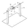
- FIG. 1 is a perspective view showing the tape winding jig 20
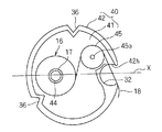
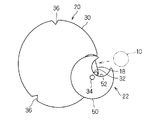
- FIG. 2 is a side view showing the internal structure of the jig main body 30 of the tape winding jig 20, and FIGS. It is explanatory drawing which shows the operation
- the tape winding jig 20 is for winding the tape 18 around a long member.
- an electric wire bundle 10 in which electric wires are bundled is assumed as the long member.
- the electric wire bundle 10 is usually a part of a wire harness in which a plurality of electric wires are bundled while being appropriately branched. That is, as a wiring member in a vehicle or the like, a wire harness in which a plurality of electric wires are bundled while being branched according to a wiring route in the vehicle is used.
- the wire bundle 10 which is a part of the wire harness is bundled by winding the tape 18 in order to maintain a branching form corresponding to the wiring path.
- This tape winding jig 20 is used for winding the tape 18 around the electric wire bundle 10.
- the tape winding jig 20 is used not only for winding the tape 18 around the electric wire bundle 10 but also when winding the tape around a tube such as a corrugated tube sheathed on the electric wire, or when winding the tape around a bundle such as a tube. be able to.
- the tape winding jig 20 includes a jig body 30 and a lid 50.
- the jig main body 30 is a member formed of resin, metal, or the like, and a setting recess 32 is formed on the outer periphery.
- the setting recess 32 extends in the thickness direction of the jig main body 30 (the thickness direction coincides with the axial direction of the tape winding body 16 supported by the tape winding body support portion 44). It is formed in a concave groove shape that is recessed in a U-shape.
- the setting recess 32 is set to a size that allows the electric wire bundle 10 to be wound around the tape 18 to be disposed. That is, the width dimension and depth dimension of the setting recess 32 are set to be equal to or larger than the outer diameter dimension of the wire bundle 10.
- the setting recesses 32 are open on both sides of the jig body 30 in the thickness direction. For this reason, when the extending direction intermediate portion of the wire bundle 10 is disposed in the setting recess 32 in a posture in which the extending direction of the wire bundle 10 is aligned with the extending direction of the setting recess 32, the setting recess The both ends of the wire bundle 10 extend outward from the openings on both sides of 32.
- the lid portion 50 is a member formed of resin, metal, or the like.
- the lid portion 50 opens the jig body 30 to open the outer peripheral side opening of the setting concave portion 32 and closes the outer peripheral side opening of the setting concave portion 32. It is supported by posture change between postures.
- the outer shape of the lid 50 is formed in a cylindrical shape.
- a lid-side recess 52 is formed on the outer periphery of the lid 50.
- the lid-side recess 52 is formed in a groove shape that is recessed in a C-shape or U-shape extending along the thickness direction of the lid 50.
- the lid side recess 52 is set to a size that allows the wire bundle 10 to be wound around the tape 18 to be disposed.
- the width dimension and depth dimension of the lid-side recess 52 are set to be equal to or larger than the outer diameter dimension of the wire bundle 10.
- the lid-side recess 52 is formed in the same size and shape as the setting recess 32.
- the lid-side recess 52 is set to a depth that does not reach the center of the lid 50.
- the lid 50 is rotatably supported on one side of the outer periphery of the set recess 32 in the jig main body 30 via a shaft 34.
- the lid 50 is rotated so that the setting concave portion 32 and the lid-side concave portion 52 coincide with each other.
- One side part of the outer peripheral side opening of the recessed part 52 will be in the state which closes the outer side opening of the recessed part 32 for a setting (refer FIG.1 and FIG.4).
- position of the cover part 50 is a closed attitude
- the lid 50 is rotated so that the outer peripheral side opening of the lid side concave portion 52 is positioned on the outer peripheral side of the jig main body 30 with respect to the outer opening of the setting concave portion 32. Then, when the jig main body 30 is viewed along the thickness direction, the outer opening of the setting recess 32 communicates with the outside through the lid recess 52 and the outer peripheral opening (see FIG. 4). ). For this reason, the wire bundle 10 is relatively pushed into the setting recess 32 through the outer peripheral side opening of the lid side recess 52, the internal space of the lid side recess 52, and the outer opening of the setting recess 32. Will be able to.
- the other side portion of the opening on the outer peripheral side of the lid-side recess 52 in the lid 50 is located in the setting recess 32. Yes.
- the electric wire bundle 10 comes into contact with the other side portion of the outer peripheral side opening of the lid side recess 52 in the lid portion 50.
- the electric wire bundle 10 pushes the other side portion of the outer peripheral side opening of the lid side concave portion 52 of the lid portion 50, while setting the concave portion for setting. 32. Therefore, the position of the lid 50 can be changed from the open position to the closed position by the operation of relatively pushing the wire bundle 10 into the setting recess 32.
- the wire bundle 10 When the lid 50 is in the closed position, the wire bundle 10 is surrounded by the setting recess 32 and the lid-side recess 52 when the jig main body 30 is viewed along its thickness direction. Can rotate relative to each other within the space surrounded by the set recess 32 and the lid-side recess 52. That is, the tape winding jig 20 including the jig main body 30 and the lid 50 rotates around the electric wire bundle 10 in a state where the electric wire bundle 10 is disposed in the setting concave portion 32 and the lid-side concave portion 52. Can do.
- the wire bundle 10 when the wire bundle 10 is relatively moved toward the lid-side recess 52 in a state where the wire bundle 10 is disposed in the setting recess 32 and the lid-side recess 52, the wire bundle 10 is moved to the lid side.
- the concave portion 52 is pushed toward the outer peripheral side of the jig main body 30.
- position of the cover part 50 changes from a closed attitude
- the lid portion 50 is closed with the concave portion 52 coinciding with the setting concave portion 32, and the concave portion 52 is It supports so that attitude
- the lid portion 50 can be changed from the open posture to the closed posture, and when the wire bundle 10 is removed from the setting recess 32, the lid portion 50 is removed.
- the posture can be changed from the closed posture to the open posture.
- the set recess 22 and the lid 50 formed in the jig body 30 constitute a set portion 22 that can be detachably and rotatably set at the intermediate portion in the extending direction of the wire bundle 10. ing.
- a pair of lid portions 50 are provided on both sides in the thickness direction of the jig main body 30 so that the tape winding jig 20 can rotate around the wire bundle 10 in a posture that is not inclined as much as possible.
- the number of the cover parts 50 may be one.
- the jig body part 30 is provided with a tape winding body support part 44.
- the tape 18 has a pressure-sensitive adhesive layer formed on one main surface of a belt-shaped substrate formed of resin or the like, and the tape wound body 16 wound around the single cylindrical core 17 a plurality of times.
- the tape winding body support portion 44 is provided so as to be rotatable around the wire bundle 10 together with the set portion 22 around the set portion 22, and in a state in which the tape 18 can be drawn around the set portion 22. It is comprised so that it may support.
- the jig main body portion 30 is configured by a combination of a main body side accommodating portion 40 and a main body side lid portion 48.
- the outer shape of the entire jig body 30 will be described.
- the jig body 30 is formed in a short elliptical columnar outer shape. That is, the jig body 30 is formed in a shape surrounded by a curved surface that draws an ellipse.
- the setting recess 32 is formed on one side of the outer periphery of the jig main body 30 in the minor axis X direction of the elliptical shape.
- a recess 36 is formed on the outer periphery of the jig body 30 other than the portion where the set recess 32 is formed.
- the recesses 36 are formed at two locations on the outer periphery of the jig body 30 that are approximately the same distance away from the setting recess 32.
- the recess 36 is formed in a triangular groove shape extending along the thickness direction of the jig body 30. The recess 36 can be used as a clue when the jig body 30 is gripped by a human finger or a robot hand, and can be handled so as not to slide as much as possible.
- the main body side accommodating portion 40 has a configuration in which a surrounding wall portion 42 is formed around one main surface of an elliptical plate portion 41 (see FIG. 2).
- the surrounding wall portion 42 is formed not only in the edge portion forming the outer periphery of the ellipse in the plate portion 41 but also in the edge portion where the setting recess 32 is formed and the edge portion where the recess 36 is formed.
- a tape drawing opening 42h communicating with the inside and outside of the surrounding wall portion 42 is formed in a portion adjacent to the outer peripheral side opening of the setting recess 32 in the edge portion where the setting recess 32 is formed. Therefore, the surrounding wall portion 42 is formed on the entire peripheral edge portion of the plate portion 41 except for the tape drawing opening 42h formed at a part of the edge portion where the setting concave portion 32 is formed.
- a tape wound body support portion 44 is provided in the main body side accommodating portion 40.
- a tape wound body support portion 44 is provided on the inner surface of the plate portion 41 and on the opposite side of the setting recess 32 across the center of the plate portion 41, that is, the other side portion in the minor axis X direction.
- the tape winding body support portion 44 is formed in a round bar shape or a cylindrical shape that can be inserted into the winding core 17, and protrudes from the inner surface of the plate portion 41.
- the tape wound body support portion 44 itself may be configured to be rotatably supported with respect to the main body side housing portion 40 by a bearing structure or the like, or the tape wound body support portion 44 itself may not be rotatable.
- the structure which protrudes in the side accommodating part 40 and the winding core 17 rotates with respect to the tape winding body 16 may be sufficient.
- a guide roller 45 is provided at a position shifted from between the tape wound body support portion 44 and the set recess 32 in the main body side accommodating portion 40.
- the guide roller 45 is formed in a short columnar shape, and is supported so as to be rotatable with respect to the main body side accommodating portion 40 via a shaft portion 45a.
- the tape winding body 16 is rotatably supported by the tape winding body support portion 44, and the tape 18 drawn from the tape winding body 16 is directed to the tape drawing opening 42h via the guide roller 45. Furthermore, it passes through the set recess 32 and is disposed toward one outer side portion of the outer peripheral side opening of the set recess 32. At this time, the adhesive layer of the tape 18 is disposed in the setting recess 32 so as to face the outer peripheral side opening of the setting recess 32. For this reason, when the wire bundle 10 is pushed into the setting recess 32, the adhesive layer of the tape 18 is attached to the outer periphery of the wire bundle 10. In the above state, the surface of the tape 18 opposite to the adhesive layer is guided by the guide roller 45 while being in contact with the guide roller 45.
- the main body side lid portion 48 is formed in the same elliptical plate shape as the plate portion 41 and is attached to the main body side accommodation portion 40 so as to close the opening of the main body side accommodation portion 40 opposite to the plate portion 41. .
- the attachment state of both is maintained by a detachable structure such as a screwing or locking structure.
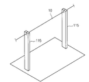
- a wire bundle 10 in which a plurality of wires 10a are bundled is supported (step (a)).
- two distant portions of the wire bundle 10 are supported by the two wire bundle support members 115 so that the intermediate portion in the extending direction of the wire bundle 10 is supported away from the surroundings.
- the supporting portion of the wire bundle 10 may be an intermediate portion in the extending direction of the wire bundle 10, or an end connector or the like.
- the wire bundle 10 may be in a direction (including the horizontal direction) intersecting the vertical direction that is the direction of gravity, or may be in the vertical direction.
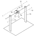
- the set part 22 is set in the extending direction intermediate part of the wire bundle 10 (see step (b), FIG. 3 and FIG. 4).
- the intermediate portion in the extending direction of the wire bundle 10 is used for setting.
- the tape winding jig 20 is pressed against the intermediate portion in the extending direction of the wire bundle 10 so as to be pushed into the recess 32.
- the lid 50 is pushed by the wire bundle 10 to change the posture of the lid 50 to the closed posture, and the intermediate portion in the extending direction of the wire bundle 10 is accommodated between the setting recess 32 and the lid-side recess 52. .
- step (c) the end portion of the tape 18 drawn from the tape winding body 16 supported by the tape winding body support portion 44 is attached to the wire bundle 10 (step (c)).
- step (b) and step (c) are performed at the same time, but it is not always necessary.
- the end portion of the tape 18 may be attached to the intermediate portion in the extending direction of the electric wire bundle 10 before or after the setting portion 22 is set in the intermediate portion in the extending direction of the electric wire bundle 10.
- the tape winding jig 20 is rotated around the wire bundle 10 in a state where the set portion 22 is set at the intermediate portion in the extending direction of the wire bundle 10 (step (d )). Then, the tape winding jig 20 rotates together with the tape winding body 16 and the tape 18 drawn from the tape winding body 16 with the end portion of the tape 18 being attached to the outer periphery of the wire bundle 10. 18 is sequentially wound around the outer circumference of the wire bundle 10 while being drawn out from the tape winding body 16. It should be noted that a tension according to the force required to pull out the tape 18 from the tape winding 16 acts on the tape 18 drawn out from the tape winding 16 against the adhesive force of the tape 18.
- the tape 18 is wound so as to be in close contact with the wire bundle 10 in a state where a certain amount of tension is applied.
- the tape winding jig 20 is rotated around the wire bundle 10 a desired number of times (one or more times), the tape 18 is wound around the wire bundle 10 a desired number of times.
- the lid portion 50 is in the open posture. Then, the tape winding jig 20 is removed from the wire bundle 10. Then, when the portion of the tape 18 wound around the wire bundle 10 and the portion remaining on the tape winding jig 20 side is cut with a finger, a cutter or the like, as shown in FIG. 9, the tape-wrapped wire bundle 110A is manufactured.
- the tape winding jig 20 is moved along the extending direction of the electric wire bundle 10 while the tape winding jig 20 is moved to the electric wire bundle 10.
- a tape-wrapped electric wire bundle 110 ⁇ / b> B in which the tape 18 is spirally wound around the electric wire bundle 10 as shown in FIG. 11 can be manufactured.
- the bundle 10 can be wound roughly (in a mode in which the tape 18 is wound with a gap between the spirals) or densely wound (in a mode in which the tape 18 is partially overlapped between the spirals). You can also.
- the set portion 22 is rotatably set at the intermediate portion in the extending direction of the electric wire bundle 10 to support the tape winding body.
- the tape winding jig 20 is rotatably supported with respect to the electric wire bundle 10 by its own set portion 22, the tape winding jig 20 is separately rotatably supported around the tape winding jig 20. There is no need to provide a roller or the like. For this reason, the space which can rotate the tape winding jig
- the wire harness has a trunk portion and a plurality of branch portions.
- the tape 18 is wound around the portion, another portion of the electric wire bundle 10 is present nearby (see the two-dot chain line in FIG. 6).
- a space saving that allows the tape winding jig 20 to rotate is saved. If it can be secured, the tape 18 can be wound. Therefore, the winding operation of the tape 18 can be easily performed at a place where a plurality of branch line portions are densely arranged in the wire harness.
- the tape winding jig 20 is light and compact, it can be easily moved to perform tape winding operations in a wider variety of places.
- the winding operation of the tape 18 rotates the tape winding jig 20 around the electric wire bundle 10. This can be done by applying a force in the direction to be applied. For this reason, as shown in FIG. 12, the winding operation of the tape 18 can be easily performed by, for example, the robot 120 (here, the fingers of a humanoid robot) which is inferior in dexterity compared to the manual operation. This contributes to the automation of wire harness manufacturing work.
- the tape winding jig 20 includes a jig main body 30 having a setting concave portion 32 formed on the outer periphery, an opening posture in which the jig main body 30 opens the outer peripheral side opening of the setting concave portion 32, and a setting concave portion.
- the intermediate portion in the extending direction of the wire bundle 10 can be easily and reliably set on the set portion 22. After that, if the lid portion 50 is changed to the open posture, the set portion 22 can be easily removed from the intermediate portion in the extending direction of the wire bundle 10.
- the jig main body 30 is formed in a short elliptical columnar outer shape and is surrounded by a curved surface that protrudes outward. For this reason, when rotating the tape winding jig 20 around the electric wire bundle 10, the jig main body 30 is not easily caught by surrounding members (for example, other electric wires).
- the lid portion 50 is also formed in a short elliptical columnar outer shape and is surrounded by a curved surface that protrudes outward. For this reason, when the tape winding jig 20 is rotated around the wire bundle 10, the lid 50 is not easily caught by surrounding members (for example, other electric wires).
- the jig main body part or the lid part is not formed in a short elliptical columnar outer shape and is formed in a short columnar outer shape, it is difficult to be caught by surrounding members. That is, when the jig main body part or the lid part is formed in a shape surrounded by a curved surface that protrudes outward, it is difficult to catch them on the surrounding members.
- the jig body 30 is formed into a short elliptical columnar outer shape, that is, a shape surrounded by a curved surface that draws an ellipse, and a setting recess 32 is formed on one side of the short axis X direction, Since the tape winding body support portion 44 is provided on the other side of the short axis X direction, the space required for rotating the tape winding jig 20 around the wire bundle 10 can be further reduced. Since the jig body 30 rotates around the wire bundle 10 disposed in the set recess 32, the size of the set recess 32 and the portion opposite to the set recess 32 can be reduced. This is because the locus when the jig main body 30 rotates around the wire bundle 10 becomes small.
- the jig main body 30 can be more securely held with the recess 36 being used as a clue, more reliably suppressing slipping and the like.
- the jig body 30 is less likely to be caught by surrounding members when the tape winding jig 20 is rotated around the wire bundle 10 as compared with the case where a convex portion is formed on the outer periphery of the jig body.
- the configuration of the lid 50 that enables opening and closing of the opening 32 for setting is not limited to the above example.
- a lid that can be opened and closed by sliding may be provided with respect to the opening of the set recess.
- a lid that can be elastically deformed and opened / closed may be provided with respect to the opening of the set recess.
- a lid is provided. Further, it is not essential that the jig main body has the shape described in the above embodiment.
- the set part 222 is formed at one end of the long jig main body 240, and the tape winding body support 244 is provided at the other end. It has been.
- the jig body 240 is formed in an elongated plate shape.
- the set portion 222 is formed in a C shape. One end of the set portion 222 is connected to one end of the jig main body 240 in a posture in which the opening of the set portion 222 faces the jig main body 240. A space that can accommodate the wire bundle 10 is formed in the set portion 222.
- the set part 222 is formed to be elastically deformable, and the opening width of the set part 222 is set larger than the outer diameter dimension of the wire bundle 10. Then, the wire bundle 10 can be set in the set portion 222 by elastically expanding the opening of the set portion 222. Thereby, the set part 222 can be set to be attachable and detachable and rotatable at an intermediate part in the extending direction of the wire bundle 10.
- the tape winding body support portion 244 is formed in a round bar shape or a cylindrical shape, like the tape winding body support portion 44.
- One end of the tape winding body support 244 is placed on the other side of the jig main body 240 in a posture in which the axial direction of the tape winding body support 244 coincides with the extending direction of the wire bundle 10 set on the set unit 222. It is supported at the end.
- the tape winding body support part 244 is formed with a retaining protrusion for preventing the winding core 17 from coming off.
- tape 18 was pulled out from tape winding body 16 supported by tape winding body support part 244, and the end of the tape 18 was moved. It is attached to the outer periphery of the wire bundle 10. Thereafter, if the tape winding jig 220 is rotated around the electric wire bundle 10, the tape 18 can be wound around the electric wire bundle 10 as in the above embodiment.
Landscapes
- Engineering & Computer Science (AREA)
- Mechanical Engineering (AREA)
- Basic Packing Technique (AREA)
- Manufacturing Of Electric Cables (AREA)
Abstract
電線等の長尺部材の周囲に広い作業スペースを確保困難な場合でも、当該長尺部材にテープを容易に巻付けられるようにすることを目的とする。テープ巻治具は、長尺部材(電線束等)にテープを巻付けるためのものである。テープ巻治具は、長尺部材の延在方向中間部に着脱可能かつ回転可能にセット可能なセット部と、セット部の周りでセット部と共に長尺部材周りに回転可能に設けられ、セット部の周りでテープを引出可能な状態でテープ巻回体を支持するテープ巻回体支持部とを備える。
Description
この発明は、電線等にテープを巻付けるための技術に関する。
特許文献1は、回転可能に支持された回転ドラムの周縁に被結束体を保持する支持部を形成すると共に、回転ドラムにおける支持部よりも回転方向前方側にテープの端部を保持する保持部を設けたテープ巻き付け機を開示している。特許文献1では、支持部に被結束体が保持された状態で、回転ドラムが回転することで、保持部に端部が保持されたテープが被結束体に巻き付けられる。
特許文献2は、スリット状の切欠きが形成された駆動ギヤに、当該駆動ギヤと共に回転するテープ巻き湯突起を設けた自動テープ巻き装置を開示している。特許文献2では、スリット状の切欠き内にテープを配設した状態で、駆動ギヤと共にテープ巻きユニットを回転させることで、テープがハーネスに巻付けられる。
特許文献3は、回転可能に支持されると共に組み付け体を挿抜するための挿抜口が形成されたテープ巻きドラムと、テープ巻きドラムに対してテープを供給するテープ供給機構とを備えた部分テープ巻き装置を開示している。そして、組み付け体をテープ巻きドラムの挿抜口内に導入した状態で、テープ巻きドラムを回転させると、組み付け体に挿抜口内のテープが巻付けられる。
しかしながら、特許文献1に開示の技術によると、回転ドラムの周りに、当該回転ドラムを回転可能に支持する構成を採用する必要がある。このため、回転ドラムの周辺構成が大型化し、ハーネスの周辺スペースが大きく開放された状況でしか、テープ巻付作業を実施できないという問題がある。特許文献2及び3でも同様の問題がある。
そこで、本発明は、電線等の長尺部材の周囲に広い作業スペースを確保困難な場合でも、当該長尺部材にテープを容易に巻付けられるようにすることを目的とする。
上記課題を解決するため、第1の態様は、長尺部材にテープを巻付けるためのテープ巻治具であって、長尺部材の延在方向中間部に着脱可能かつ回転可能にセット可能なセット部と、前記セット部の周りで前記セット部と共に長尺部材周りに回転可能に設けられ、前記セット部の周りでテープを引出可能な状態でテープ巻回体を支持するテープ巻回体支持部とを備える。
第2の態様は、第1の態様に係るテープ巻治具であって、外周にセット用凹部が形成された治具本体部と、前記治具本体部に、前記セット用凹部の外周側開口を開放させる開姿勢と前記セット用凹部の外周側開口を閉じる閉姿勢との間で姿勢変更可能に支持された蓋部とを備え、前記セット部が前記セット用凹部と前記蓋部とを含み、前記テープ巻回体支持部が前記治具本体部に設けられているものである。
第3の態様は、第2の態様に係るテープ巻治具であって、前記治具本体部は、外向きに凸となる曲面で周囲を囲われた形状に形成されているものである。
第4の態様は、第2又は第3の態様に係るテープ巻治具であって、前記治具本体部が、楕円を描く曲面で周囲を囲われた形状に形成され、その短軸方向一方側の部分に前記セット用凹部が形成されているものである。
第5の態様は、第3又は第4の態様に係るテープ巻治具であって、前記治具本体部の外周であって前記セット用凹部が形成された部分以外の部分に凹部が形成されているものである。
第6の態様は、第2~第5のいずれか1つの態様に係るテープ巻治具であって、前記蓋部は、外向きに凸となる曲面で周囲を囲われた形状に形成されているものである。
第7の態様は、第1~第6のいずれか1つの態様に係るテープ巻治具を用いてテープを長尺部材に巻付けるテープ巻付長尺部材の製造方法であって、(a)長尺部材を支持する工程と、(b)前記セット部を長尺部材の延在方向中間部にセットする工程と、(c)前記テープ巻回体支持部に支持されたテープ巻回体から引出されたテープの端部を長尺部材に取付ける工程と、(d)前記セット部が長尺部材の延在方向中間部にセットされた状態で、前記テープ巻治具を長尺部材の周りに回転させる工程とを備える。
第8の態様は、第7の態様に係るテープ巻付長尺部材の製造方法であって、前記工程(d)において、前記テープ巻治具を長尺部材の延在方向に沿って移動させつつ、前記テープ巻治具を長尺部材の周りに回転させるものである。
第1の態様によると、セット部を長尺部材の延在方向中間部に回転可能にセットし、テープ巻回体支持部に支持されたテープ巻回体から引出されたテープの端部を長尺部材に取付け、この状態で、テープ巻治具を長尺部材周りに回転させると、テープ巻回体から引出されたテープが長尺部材に巻付けられる。この際、長尺部材の周りには、テープ巻治具を回転させることが可能なスペースが存在していればよい。このため、電線等の長尺部材の周囲に広い作業スペースを確保困難な場合でも、当該長尺部材にテープを容易に巻付けることができる。
第2の態様によると、蓋部を開姿勢にした状態で、長尺部材の延在方向中間部を前記セット用凹部に配設し、この後、蓋部を閉姿勢に姿勢変更すれば、長尺部材の延在方向中間部をセット部に容易かつ確実にセットできる。また、この後、蓋部を開姿勢に姿勢変更すれば、セット部を、長尺部材の延在方向中間部から容易に外すことができる。
第3の態様によると、テープ巻治具を長尺部材の周りに回転させる際に、治具本体部が周囲の部材に引っ掛かり難い。
第4の態様によると、テープ巻治具は、治具本体部の点軸方向一方側のセット用凹部にセットされた長尺部材周りに回転する。このため、長尺部材周りにおいてテープ巻治具を回転させるのに必要となるスペースをより小さくできる。また、治具本体部のうち長尺部材から見て外側を向く部分は、なだらかな外向きの弧を描くため、治具本体部が周囲の部材に引っ掛かり難い。
第5の態様によると、凹部を手がかりとして治具本体部を保持することができる。また、治具本体部に凸部を形成する場合と比べ、テープ巻治具を長尺部材の周りに回転させる際に、治具本体部が周囲の部材に引っ掛かり難い。
第6の態様によると、テープ巻治具を長尺部材の周りに回転させる際に、蓋部が周囲の部材に引っ掛かり難い。
第7の態様によると、セット部が長尺部材の延在方向中間部にセットされることで、テープ巻治具が長尺部材の周りに回転可能に配設される。この状態で、テープ巻治具を長尺部材の周りに回転させることで、電線等の長尺部材の周囲に広い作業スペースを確保困難な場合でも、当該長尺部材にテープを容易に巻付けることができる。
第8の態様によると、テープを長尺部材の周りに螺旋状に巻付けることができる。
以下、実施形態に係るテープ巻治具及びテープ巻治具を用いたテープ巻付長尺部材の製造方法について説明する。
<テープ巻治具について>
まず、テープ巻治具について説明する。図1はテープ巻治具20を示す斜視図であり、図2はテープ巻治具20の治具本体部30の内部構造を示す側面図であり、図3及び図4はテープ巻治具20を電線束10にセットする動作を示す説明図である。
まず、テープ巻治具について説明する。図1はテープ巻治具20を示す斜視図であり、図2はテープ巻治具20の治具本体部30の内部構造を示す側面図であり、図3及び図4はテープ巻治具20を電線束10にセットする動作を示す説明図である。
テープ巻治具20は、長尺部材にテープ18を巻付けるためのものである。ここでは、長尺部材として、電線を束ねた電線束10を想定している。電線束10は、通常、複数の電線が適宜分岐しつつ束ねられたワイヤーハーネスの一部である。すなわち、車両等における配線部材として、複数の電線を、車両における配線経路に応じて分岐しつつ束ねたワイヤーハーネスが用いられる。ワイヤーハーネスの一部である電線束10は、配線経路に応じた分岐形態を保つためテープ18が巻回されて束ねられる。本テープ巻治具20は、かかる電線束10にテープ18を巻回するために用いられる。本テープ巻治具20は、電線束10にテープ18を巻付ける以外に、電線に外装したコルゲートチューブ等のチューブにテープを巻付ける場合、チューブ等の束にテープを巻付ける場合等にも用いることができる。
テープ巻治具20は、治具本体部30と、蓋部50とを備える。
治具本体部30は、樹脂又は金属等によって形成された部材であり、外周にセット用凹部32が形成されている。セット用凹部32は、治具本体部30の厚み方向(この厚み方向はテープ巻回体支持部44によって支持されるテープ巻回体16の軸方向と一致する)に沿って延在するC字状又はU字状に凹む凹溝状に形成されている。セット用凹部32は、テープ18の巻付対象となる電線束10を配設可能な大きさに設定されている。すなわち、セット用凹部32の幅寸法及び深さ寸法は、電線束10の外径寸法と同じかこれよりも大きく設定されている。また、治具本体部30の厚み方向両側において、セット用凹部32は開口している。このため、電線束10の延在方向をセット用凹部32の延在方向に沿わせた姿勢で、電線束10の延在方向中間部をセット用凹部32内に配設すると、当該セット用凹部32の両側開口から電線束10の両端部側が外方に向けて延出する。
蓋部50は、樹脂又は金属等によって形成された部材であり、治具本体部30に、セット用凹部32の外周側開口を開放させる開姿勢と、セット用凹部32の外周側開口を閉じる閉姿勢との間で姿勢変更に支持されている。ここでは、蓋部50の外形は、円柱状に形成されている。また、蓋部50の外周に、蓋側凹部52が形成されている。蓋側凹部52は、蓋部50の厚み方向に沿って延在するC字状又はU字状に凹む凹溝状に形成されている。蓋側凹部52は、テープ18の巻付対象となる電線束10を配設可能な大きさに設定されている。すなわち、蓋側凹部52の幅寸法及び深さ寸法は、電線束10の外径寸法と同じかこれよりも大きく設定されている。ここでは、蓋側凹部52は、上記セット用凹部32と同じ大きさ及び形状に形成されている。この蓋側凹部52は、蓋部50の中心には達し無い程度の深さ寸法に設定されている。
蓋部50は、治具本体部30のうちセット用凹部32の外周側開口の一方の側部に、軸部34を介して回転可能に支持されている。そして、治具本体部30をその厚み方向に沿って見た場合において、セット用凹部32と蓋側凹部52とが一致するように、蓋部50を回転させると、蓋部50のうち蓋側凹部52の外周側開口の一方側部が、セット用凹部32の外側開口を閉じる状態となる(図1及び図4参照)。蓋部50の当該姿勢が閉姿勢である。また、この閉姿勢から、蓋側凹部52の外周側開口がセット用凹部32の外側開口に対して治具本体部30の外周側に位置するように、蓋部50を回転させる。すると、治具本体部30をその厚み方向に沿って見た場合において、セット用凹部32の外側開口は、蓋側凹部52及びその外周側開口を通じて、外部に連通するようになる(図4参照)。このため、電線束10を、蓋側凹部52の外周側開口、蓋側凹部52の内部空間、さらに、セット用凹部32の外側開口を通じて、セット用凹部32内に向けて相対的に押込むことができるようになる。
また、上記開姿勢において、治具本体部30をその厚み方向に沿って見ると、蓋部50のうち蓋側凹部52の外周側開口の他方側部分は、セット用凹部32内に位置している。このため、電線束10をセット用凹部32内に相対的に押込む際、電線束10は、蓋部50のうち蓋側凹部52の外周側開口の他方側部分に当接する。この状態から、電線束10をさらにセット用凹部32に相対的に押込むと、電線束10は、蓋部50のうち蓋側凹部52の外周側開口の他方側部分を押込みつつ、セット用凹部32内に収容される。このため、電線束10をセット用凹部32内に相対的に押込む作業によって、蓋部50を開姿勢から閉姿勢に姿勢変更させることができる。
蓋部50が閉姿勢とされた状態では、治具本体部30をその厚み方向に沿って見ると、電線束10は、セット用凹部32及び蓋側凹部52によって囲まれており、電線束10はセット用凹部32及び蓋側凹部52によって囲まれた空間内で相対回転することができる。つまり、セット用凹部32及び蓋側凹部52内に電線束10が配設された状態で、治具本体部30及び蓋部50を含むテープ巻治具20は、電線束10周りに回転することができる。
また、電線束10が、セット用凹部32及び蓋側凹部52内に配設された状態で、電線束10を蓋側凹部52側に向けて相対的に移動させると、電線束10が蓋側凹部52を治具本体部30の外周側に向けて押す。これにより、蓋部50が閉姿勢から開姿勢に姿勢変更し、電線束10をセット用凹部32から取外せるようになる。
つまり、蓋部50に、セット用凹部32の凹み形状と同じ形状部分を含む凹部52を形成した上で、蓋部50を、凹部52がセット用凹部32と一致する閉姿勢と、凹部52がセット用凹部32から外周側開口に移動した開姿勢との間で、姿勢変更可能に支持する。また、開姿勢において、蓋部50のうち凹部52の開口一方側部分がセット用凹部32の外周側開口に位置するようにする。これにより、電線束10をセット用凹部32に押込む際に、蓋部50を開姿勢から閉姿勢に姿勢変更させることができ、電線束10をセット用凹部32から取外す際に蓋部50を閉姿勢から開姿勢に姿勢変更させることができる。
本実施形態では、上記治具本体部30に形成されたセット用凹部32及び蓋部50によって、電線束10の延在方向中間部に着脱可能かつ回転可能にセット可能なセット部22を構成している。
なお、ここでは、テープ巻治具20が、なるべく傾かない姿勢で、電線束10の周りを回転できるように、一対の蓋部50が、治具本体部30の厚み方向両側に設けられている。もっとも、蓋部50は、1つであってもよい。
上記治具本体部30には、テープ巻回体支持部44が設けられている。ここで、テープ18は、樹脂等で形成された帯状基材の一方主面に粘着層が形成されたものであり、単筒状の巻芯17に複数回巻付けられたテープ巻回体16の形態で提供される。テープ巻回体支持部44は、セット部22の周りでセット部22と共に電線束10周りに回転可能に設けられ、当該セット部22の周りでテープ18を引出可能な状態でテープ巻回体16を支持するように構成されている。
より具体的には、上記治具本体部30は、本体側収容部40と、本体側蓋部48との組合わせにより構成されている。
この治具本体部30全体の外形状について説明すると、治具本体部30は、短楕円柱状の外形状に形成されている。つまり、治具本体部30は、楕円を描く曲面で周囲を囲まれた形状に形成されている。この治具本体部30の外周のうち前記楕円形状における短軸X方向の一方側に上記セット用凹部32が形成されている。
また、治具本体部30の外周であって上記セット用凹部32が形成された部分以外の部分に凹部36が形成されている。ここでは、凹部36は、治具本体部30の外周において、セット用凹部32からほぼ同じ距離離れた2箇所に凹部36が形成されている。凹部36は、治具本体部30の厚み方向に沿って延在する三角溝状に形成されている。この凹部36を、治具本体部30を人の手指又はロボットハンド等で掴む際等の手がかりとすることができ、治具本体部30をなるべく滑らないように取扱うことができる。
本体側収容部40及び本体側蓋部48のそれぞれの構成について説明する。
本体側収容部40は、楕円状の板部41の一方主面の周囲に囲壁部42が形成された構成とされている(図2参照)。囲壁部42は、板部41のうち楕円の外周をなす縁部分だけではなく、セット用凹部32が形成された縁部分、及び、凹部36が形成された縁部分にも形成されている。もっとも、セット用凹部32が形成された縁部分のうちセット用凹部32の外周側開口の隣の部分には、囲壁部42の内外に連通するテープ引出用開口42hが形成されている。従って、囲壁部42は、セット用凹部32が形成された縁部分の一部に形成されたテープ引出用開口42hを除いて、板部41の周縁部全体に形成されている。
上記本体側収容部40にテープ巻回体支持部44が設けられている。ここでは、上記板部41の内面であって板部41の中心を挟んでセット用凹部32の反対側、すなわち、短軸X方向の他方側の部分にテープ巻回体支持部44が設けられている。テープ巻回体支持部44は、上記巻芯17に挿入可能な丸棒状又は円筒状に形成されており、板部41の内面に突設されている。テープ巻回体16の巻芯17内にテープ巻回体支持部44を挿通することによって、テープ巻回体16がテープ18を引出可能な状態で、当該テープ巻回体支持部44によって支持される。なお、テープ巻回体支持部44自体が軸受構造等によって本体側収容部40に対して回転可能に支持された構成であってもよいし、テープ巻回体支持部44自体は回転不能に本体側収容部40に突設され、テープ巻回体16に対して巻芯17が回転する構成であってもよい。
また、本体側収容部40のうちテープ巻回体支持部44とセット用凹部32との間からずれた位置にガイドローラ45が設けられている。ガイドローラ45は、短円柱状に形成されており、本体側収容部40に対して軸部45aを介して回転可能に支持されている。
そして、テープ巻回体16がテープ巻回体支持部44に回転可能に支持されると共に、テープ巻回体16から引出されたテープ18がガイドローラ45を経由してテープ引出用開口42hに向けて引出され、さらに、セット用凹部32を通って当該セット用凹部32の外周側開口の一方側外方部分に向けて配設される。この際、テープ18の粘着層が、セット用凹部32内においてセット用凹部32の外周側開口を向くように配設される。このため、電線束10をセット用凹部32内に向けて押込むと、テープ18の粘着層が電線束10の外周に取付られるようになる。また、上記状態では、テープ18のうち粘着層とは反対側の面がガイドローラ45に接触しつつ当該ガイドローラ45によって案内されることになる。
本体側蓋部48は、板部41と同じ楕円板状に形成されており、本体側収容部40のうち板部41とは反対側の開口を閉じるように、本体側収容部40に取付られる。両者の取付状態は、ネジ止、係止構造等、着脱可能な構造によって維持される。
<テープ巻付長尺部材の製造方法について>
上記テープ巻治具20を用いたテープ巻付長尺部材の製造方法について説明する。ここでは、テープ巻付長尺部材が、テープ18が巻付けられた電線束10、すなわち、テープ巻付電線束110Aである例で説明する。
上記テープ巻治具20を用いたテープ巻付長尺部材の製造方法について説明する。ここでは、テープ巻付長尺部材が、テープ18が巻付けられた電線束10、すなわち、テープ巻付電線束110Aである例で説明する。
まず、図5に示すように、複数の電線10aが束ねられた電線束10を支持する(工程(a))。この際、電線束10のうち離れた2箇所を2つの電線束支持部材115によって支持し、電線束10の延在方向中間部が周囲から離れて支持された状態とする。電線束10の支持箇所は、電線束10の延在方向中間部であってもよいし、端部のコネクタ等であってもよい。また、電線束10は、重力方向である鉛直方向に対して交差する方向(水平方向を含む)であってもよいし、鉛直方向であってもよい。
そして、セット部22を電線束10の延在方向中間部にセットする(工程(b)、図3及び図4参照)。具体的には、蓋部50を開姿勢にすると共にテープ18がテープ引出用開口42hから引出されセット用凹部32内に配設された状態で、電線束10の延在方向中間部をセット用凹部32内に向けて押込むように、テープ巻治具20を電線束10の延在方向中間部に押付ける。すると、電線束10により蓋部50が押されて蓋部50が閉姿勢に姿勢変更すると共に電線束10の延在方向中間部がセット用凹部32と蓋側凹部52との間に収容される。また、同時に、テープ巻回体支持部44に支持されたテープ巻回体16から引出されたテープ18の端部が電線束10に取付られる(工程(c))。ここでは、工程(b)と工程(c)とは同時に行われることになるが、必ずしもその必要は無い。例えば、セット部22を電線束10の延在方向中間部にセットする前又は後、テープ18の端部を電線束10の延在方向中間部に取付けるようにしてもよい。
そして、図6~図8に示すように、セット部22が電線束10の延在方向中間部にセットされた状態で、テープ巻治具20を電線束10の周りに回転させる(工程(d))。すると、テープ18の端部が電線束10の外周囲に取付けられた状態で、テープ巻治具20がテープ巻回体16及びテープ巻回体16から引出されたテープ18と共に回転するため、テープ18がテープ巻回体16から引出されつつ、電線束10の外周に順次巻付けられる。なお、テープ巻回体16から引出されるテープ18に対しては、テープ18の粘着力に抗して当該テープ18をテープ巻回体16から引出すのに要する力に応じた張力が作用する。このため、ある程度の張力が作用した状態で、テープ18が電線束10に対して密着するように巻付けられる。そして、所望の回数(1回以上)テープ巻治具20を電線束10の周りに回転させると、テープ18が電線束10の周りに所望の回数巻付けられた状態となる。
この後、セット用凹部32の外周側開口に向けて電線束10の延在方向中間部が移動するように、テープ巻治具20を電線束10から離すと、蓋部50が開姿勢に姿勢変更し、テープ巻治具20が電線束10から取外される。そして、テープ18のうち電線束10に巻付けられた部分とテープ巻治具20側に残存する部分との間を手指、カッター等で切ると、図9に示すように、テープ巻付電線束110Aが製造される。
なお、図10に示すように、上記工程(d)を実施する際に、テープ巻治具20を電線束10の延在方向に沿って移動させつつ、テープ巻治具20を電線束10の周りに回転させると、図11に示すように、テープ18を電線束10の周りに螺旋状に巻付けたテープ巻付電線束110Bを製造することができる。テープ巻治具20が電線束10の延在方向に沿って移動する速度と、テープ巻治具20が電線束10の周りを回転する速度とを相対的に調整することで、テープ18を電線束10に対して荒巻(テープ18が各螺旋間に隙間をあけた状態で巻かれる態様)することもできるし、密巻(テープ18が各螺旋間で部分的に重なり合いつつ巻かれる態様)することもできる。
以上のように構成されたテープ巻治具20及びテープ巻付電線束110Aの製造方法によると、セット部22を電線束10の延在方向中間部に回転可能にセットし、テープ巻回体支持部44に支持されたテープ巻回体16から引出されたテープ18の端部を電線束10に取付け、この状態で、テープ巻治具20を電線束10周りに回転させると、テープ巻回体16から引出されたテープ18が電線束10に巻付けられる。この際、テープ巻治具20は自己のセット部22によって電線束10に対して回転可能に支持されているため、テープ巻治具20の周りに別途当該テープ巻治具20を回転可能に支持するローラ等を設ける必要は無い。このため、電線束10の周りには、テープ巻治具20を回転させることが可能なスペースが存在していればよい。従って、電線束10の周囲に広い作業スペースを確保困難な場合でも、電線束10にテープ18を容易に巻付けることができる。
特に、長尺部材として複数の電線が分岐しつつ束ねられたワイヤーハーネスを想定した場合、当該ワイヤーハーネスは、幹線部分及び複数の分岐部分を有しているため、そのうちのいずれかの電線束10部分にテープ18を巻付ける際に、他の電線束10部分が近くに存在してしまう(図6の2点鎖線参照)。このように、テープ18の巻付対象となる電線束10部分に他の電線束10部分が近接している場合であっても、上記テープ巻治具20を回転させることが可能な省スペースを確保できれば、テープ18の巻付作業を実施できる。従って、ワイヤーハーネスのうち複数の枝線部分が密集しているような箇所では、テープ18の巻付作業を容易に行える。しかも、テープ巻治具20は軽量かつコンパクトな構成であるため、簡単に移動させてより広範かつ多様な場所のテープ巻付作業を実施できる。
また、テープ巻治具20は、自己のセット部22によって電線束10に対して回転可能に支持されているため、テープ18の巻付作業は、電線束10周りでテープ巻治具20を回転させる方向への力を作用させることで行える。このため、図12に示すように、例えば、人手による作業と比較して器用さに劣るロボット120(ここでは、人型ロボットの手指)によっても、テープ18の巻付作業を容易に実施できる。これにより、ワイヤーハーネスの製造作業の自働化にも貢献する。
また、テープ巻治具20は、外周にセット用凹部32が形成された治具本体部30と、治具本体部30に、セット用凹部32の外周側開口を開放させる開姿勢とセット用凹部32の外周側開口を閉じる閉姿勢との間で姿勢変更可能に支持された蓋部50とを備え、セット部22がセット用凹部32と蓋部50とを含み、テープ巻回体支持部44が治具本体部30に設けられているため、蓋部50を開姿勢にした状態で、電線束10の延在方向中間部をセット用凹部32に配設し、この後、蓋部50を閉姿勢に姿勢変更すれば、電線束10の延在方向中間部をセット部22に容易かつ確実にセットできる。また、この後、蓋部50を開姿勢西勢変更すれば、セット部22を電線束10の延在方向中間部から容易に外すことができる。
また、治具本体部30は、短楕円柱状の外形状に形成されており、周囲が外向きに凸となる曲面で囲われた形状とされている。このため、テープ巻治具20を電線束10の周りに回転させる際に、治具本体部30が周囲の部材(例えば、他の電線等)に引っ掛かり難い。
同様に、蓋部50も、短楕円柱状の外形状に形成されており、周囲が外向きに凸となる曲面で囲われた形状とされている。このため、テープ巻治具20を電線束10の周りに回転させる際に、蓋部50が周囲の部材(例えば、他の電線等)に引っ掛かり難い。
なお、治具本体部又は蓋部が、短楕円柱状の外形状に形成されておらず、短円柱状の外形状に形成されていても、周囲の部材に引っ掛かり難い。すなわち、治具本体部又は蓋部が外向きに凸となる曲面で周囲を囲われた形状に形成されていると、それらが周囲の部材に引っ掛かり難い。
しかも、治具本体部30が短楕円柱状の外形状、すなわち、楕円を描く曲面で周囲を囲われた形状に形成され、その短軸X方向一方側の部分にセット用凹部32が形成され、その短軸X方向他方側の部分にテープ巻回体支持部44が設けられているため、電線束10周りにおいてテープ巻治具20を回転させるのに必要となるスペースをより小さくできる。治具本体部30は、セット用凹部32内に配設された電線束10を中心として回転するため、セット用凹部32と、当該セット用凹部32の反対側の部分との寸法を小さくすれば、治具本体部30が電線束10周りに回転する際の軌跡が小さくなるからである。
また、治具本体部30の外周には凹部36が形成されているため、当該凹部36を手がかりとして治具本体部30をより確実に滑り等を抑制してしっかりと保持することができる。また、治具本体部の外周に凸部を形成する場合と比べて、テープ巻治具20を電線束10周りに回転させる際に、治具本体部30が周囲の部材に引っ掛かり難い。
<変形例>
セット用凹部32の開口を開閉可能にする蓋部50の構成は上記例に限られない。例えば、セット用凹部の開口に対して、スライドして開閉可能な蓋部が設けられていてもよい。また、セット用凹部の開口に対して、弾性変形して開閉可能な蓋部が設けられていてもよい。
セット用凹部32の開口を開閉可能にする蓋部50の構成は上記例に限られない。例えば、セット用凹部の開口に対して、スライドして開閉可能な蓋部が設けられていてもよい。また、セット用凹部の開口に対して、弾性変形して開閉可能な蓋部が設けられていてもよい。
蓋部が設けられていることは必須ではない。また、治具本体部が上記実施形態で説明した形状であることも必須ではない。
例えば、図13に示す変形例に係るテープ巻治具220では、長尺状の治具本体部240の一端部にセット部222が形成され、他端部にテープ巻回体支持部244が設けられている。
治具本体部240は、細長板状に形成されている。
セット部222は、C字状に形成されている。セット部222の開口を治具本体部240に向けた姿勢で、セット部222の一端部が治具本体部240の一端部に繋がっている。セット部222内には電線束10を収容可能な空間が形成されている。また、セット部222は、弾性変形可能に形成されると共に、セット部222の開口幅は、電線束10の外径寸法よりも大きく設定される。そして、セット部222の開口を弾性的に広げて、電線束10をセット部222内にセットすることができる。これにより、電線束10の延在方向中間部にセット部222を着脱可能かつ回転可能にセットすることができる。
また、テープ巻回体支持部244は、上記テープ巻回体支持部44と同様に丸棒状又は円筒状に形成されている。テープ巻回体支持部244の軸方向をセット部222にセットされる電線束10の延在方向と一致させた姿勢で、テープ巻回体支持部244の一端部が治具本体部240の他端部に支持されている。なお、テープ巻回体支持部244には、巻芯17の抜けを防止する抜止め凸部が形成されていることが好ましい。
そして、セット部222を電線束10の延在方向中間部にセットした状態で、テープ巻回体支持部244に支持されたテープ巻回体16からテープ18を引出し、そのテープ18の端部を電線束10の外周に取付ける。この後、テープ巻治具220を電線束10の周りに回転させれば、上記実施形態と同様に、テープ18を電線束10に巻付けることができる。
なお、上記実施形態及び各変形例で説明した各構成は、相互に矛盾しない限り適宜組合わせることができる。
以上のようにこの発明は詳細に説明されたが、上記した説明は、すべての局面において、例示であって、この発明がそれに限定されるものではない。例示されていない無数の変形例が、この発明の範囲から外れることなく想定され得るものと解される。
10 電線束
16 テープ巻回体
18 テープ
20、220 テープ巻治具
22、222 セット部
30 治具本体部
32 セット用凹部
36 凹部
40 本体側収容部
42 囲壁部
44、244 テープ巻回体支持部
48 本体側蓋部
50 蓋部
52 蓋側凹部
110A テープ巻付電線束
110B テープ巻付電線束
240 治具本体部
16 テープ巻回体
18 テープ
20、220 テープ巻治具
22、222 セット部
30 治具本体部
32 セット用凹部
36 凹部
40 本体側収容部
42 囲壁部
44、244 テープ巻回体支持部
48 本体側蓋部
50 蓋部
52 蓋側凹部
110A テープ巻付電線束
110B テープ巻付電線束
240 治具本体部
Claims (8)
- 長尺部材にテープを巻付けるためのテープ巻治具であって、
長尺部材の延在方向中間部に着脱可能かつ回転可能にセット可能なセット部と、
前記セット部の周りで前記セット部と共に長尺部材周りに回転可能に設けられ、前記セット部の周りでテープを引出可能な状態でテープ巻回体を支持するテープ巻回体支持部と、
を備えるテープ巻治具。 - 請求項1に記載のテープ巻治具であって、
外周にセット用凹部が形成された治具本体部と、
前記治具本体部に、前記セット用凹部の外周側開口を開放させる開姿勢と前記セット用凹部の外周側開口を閉じる閉姿勢との間で姿勢変更可能に支持された蓋部と、
を備え、
前記セット部が前記セット用凹部と前記蓋部とを含み、
前記テープ巻回体支持部が前記治具本体部に設けられている、テープ巻治具。 - 請求項2に記載のテープ巻治具であって、
前記治具本体部は、外向きに凸となる曲面で周囲を囲われた形状に形成されている、テープ巻治具。 - 請求項2又は請求項3に記載のテープ巻治具であって、
前記治具本体部が、楕円を描く曲面で周囲を囲われた形状に形成され、その短軸方向一方側の部分に前記セット用凹部が形成されている、テープ巻治具。 - 請求項3又は請求項4に記載のテープ巻治具であって、
前記治具本体部の外周であって前記セット用凹部が形成された部分以外の部分に凹部が形成されている、テープ巻治具。 - 請求項2~請求項5のいずれか1項に記載のテープ巻治具であって、
前記蓋部は、外向きに凸となる曲面で周囲を囲われた形状に形成されている、テープ巻治具。 - 請求項1~請求項6のいずれか1項に記載されたテープ巻治具を用いてテープを長尺部材に巻付けるテープ巻付長尺部材の製造方法であって、
(a)長尺部材を支持する工程と、
(b)前記セット部を長尺部材の延在方向中間部にセットする工程と、
(c)前記テープ巻回体支持部に支持されたテープ巻回体から引出されたテープの端部を長尺部材に取付ける工程と、
(d)前記セット部が長尺部材の延在方向中間部にセットされた状態で、前記テープ巻治具を長尺部材の周りに回転させる工程と、
を備えるテープ巻付長尺部材の製造方法。 - 請求項7に記載のテープ巻付長尺部材の製造方法であって、
前記工程(d)において、前記テープ巻治具を長尺部材の延在方向に沿って移動させつつ、前記テープ巻治具を長尺部材の周りに回転させる、テープ巻付長尺部材の製造方法。
Applications Claiming Priority (2)
| Application Number | Priority Date | Filing Date | Title |
|---|---|---|---|
| JP2016010537A JP2017128379A (ja) | 2016-01-22 | 2016-01-22 | テープ巻治具及びテープ巻付長尺部材の製造方法 |
| JP2016-010537 | 2016-01-22 |
Publications (1)
| Publication Number | Publication Date |
|---|---|
| WO2017126385A1 true WO2017126385A1 (ja) | 2017-07-27 |
Family
ID=59362068
Family Applications (1)
| Application Number | Title | Priority Date | Filing Date |
|---|---|---|---|
| PCT/JP2017/000620 Ceased WO2017126385A1 (ja) | 2016-01-22 | 2017-01-11 | テープ巻治具及びテープ巻付長尺部材の製造方法 |
Country Status (2)
| Country | Link |
|---|---|
| JP (1) | JP2017128379A (ja) |
| WO (1) | WO2017126385A1 (ja) |
Citations (1)
| Publication number | Priority date | Publication date | Assignee | Title |
|---|---|---|---|---|
| JP2002522309A (ja) * | 1998-08-14 | 2002-07-23 | ベルクロ インダストリーズ ビー ヴィッ | 分配ファスナーストラップ |
-
2016
- 2016-01-22 JP JP2016010537A patent/JP2017128379A/ja active Pending
-
2017
- 2017-01-11 WO PCT/JP2017/000620 patent/WO2017126385A1/ja not_active Ceased
Patent Citations (1)
| Publication number | Priority date | Publication date | Assignee | Title |
|---|---|---|---|---|
| JP2002522309A (ja) * | 1998-08-14 | 2002-07-23 | ベルクロ インダストリーズ ビー ヴィッ | 分配ファスナーストラップ |
Also Published As
| Publication number | Publication date |
|---|---|
| JP2017128379A (ja) | 2017-07-27 |
Similar Documents
| Publication | Publication Date | Title |
|---|---|---|
| EP2721701B1 (en) | Shielded wire harness and method for manufacturing the same | |
| JP6954197B2 (ja) | 組付補助部品付配線体、配線体の組付補助部品及び配線体組付物の製造方法 | |
| JP6114894B1 (ja) | 電気エネルギーと機械エネルギーとを変換する電気機械装置用コイルの保持治具 | |
| EP3629436B1 (en) | Flat cable winding device and flat cable routing structure | |
| JP5854922B2 (ja) | 線材束の接続支援器具 | |
| JP2018062387A (ja) | バンド巻付装置 | |
| JP2016063707A (ja) | チューブ状外装部材取付装置及びチューブ状外装部材付電線モジュールの製造方法 | |
| WO2017126385A1 (ja) | テープ巻治具及びテープ巻付長尺部材の製造方法 | |
| JP2018057252A (ja) | ステータの製造方法 | |
| JPH10253836A (ja) | 光ケーブル心線の余長処理装置 | |
| JP5942870B2 (ja) | 電線搬送装置及び電線処理装置 | |
| JP2022015854A (ja) | テープ巻付機 | |
| KR101155371B1 (ko) | 케이블 수납장치 | |
| JP2021062948A (ja) | テープ巻付機 | |
| KR101790071B1 (ko) | 케이블 권취장치 | |
| JP4713288B2 (ja) | 絶縁スリーブ組付け装置および絶縁スリーブ組付け方法 | |
| JP6553486B2 (ja) | グロメット電線挿通冶具 | |
| JP2013179731A (ja) | コルゲートチューブ | |
| JP2019154169A (ja) | テープ巻き付け先端工具及びこれを用いたテープ巻き付け工具 | |
| JP2006244935A (ja) | ワイヤーハーネスの梱包体及び組み付け方法 | |
| KR101371665B1 (ko) | 콜게이트튜브 삽입 부재 | |
| JP2008159364A (ja) | 電気機器のリード線端部へのスリーブ端子組み付け方法及び組み付け装置 | |
| KR101569388B1 (ko) | 평각선 권취용 지그 및 이를 적용한 평각선 권취장치 | |
| JP2021027779A (ja) | フラットケーブル巻取装置及びフラットケーブル配索構造 | |
| JP2006246655A (ja) | コルゲートチューブの取付構造、ワイヤハーネスおよびワイヤハーネスの製造方法 |
Legal Events
| Date | Code | Title | Description |
|---|---|---|---|
| 121 | Ep: the epo has been informed by wipo that ep was designated in this application |
Ref document number: 17741265 Country of ref document: EP Kind code of ref document: A1 |
|
| NENP | Non-entry into the national phase |
Ref country code: DE |
|
| 122 | Ep: pct application non-entry in european phase |
Ref document number: 17741265 Country of ref document: EP Kind code of ref document: A1 |