WO2017126342A1 - 転倒防止装置付き物品 - Google Patents
転倒防止装置付き物品 Download PDFInfo
- Publication number
- WO2017126342A1 WO2017126342A1 PCT/JP2017/000298 JP2017000298W WO2017126342A1 WO 2017126342 A1 WO2017126342 A1 WO 2017126342A1 JP 2017000298 W JP2017000298 W JP 2017000298W WO 2017126342 A1 WO2017126342 A1 WO 2017126342A1
- Authority
- WO
- WIPO (PCT)
- Prior art keywords
- damper
- article
- contact member
- furniture
- dampers
- Prior art date
- Legal status (The legal status is an assumption and is not a legal conclusion. Google has not performed a legal analysis and makes no representation as to the accuracy of the status listed.)
- Ceased
Links
Images









Classifications
-
- A—HUMAN NECESSITIES
- A47—FURNITURE; DOMESTIC ARTICLES OR APPLIANCES; COFFEE MILLS; SPICE MILLS; SUCTION CLEANERS IN GENERAL
- A47B—TABLES; DESKS; OFFICE FURNITURE; CABINETS; DRAWERS; GENERAL DETAILS OF FURNITURE
- A47B97/00—Furniture or accessories for furniture, not provided for in other groups of this subclass
-
- F—MECHANICAL ENGINEERING; LIGHTING; HEATING; WEAPONS; BLASTING
- F16—ENGINEERING ELEMENTS AND UNITS; GENERAL MEASURES FOR PRODUCING AND MAINTAINING EFFECTIVE FUNCTIONING OF MACHINES OR INSTALLATIONS; THERMAL INSULATION IN GENERAL
- F16F—SPRINGS; SHOCK-ABSORBERS; MEANS FOR DAMPING VIBRATION
- F16F9/00—Springs, vibration-dampers, shock-absorbers, or similarly-constructed movement-dampers using a fluid or the equivalent as damping medium
- F16F9/06—Springs, vibration-dampers, shock-absorbers, or similarly-constructed movement-dampers using a fluid or the equivalent as damping medium using both gas and liquid
- F16F9/061—Mono-tubular units
-
- A—HUMAN NECESSITIES
- A47—FURNITURE; DOMESTIC ARTICLES OR APPLIANCES; COFFEE MILLS; SPICE MILLS; SUCTION CLEANERS IN GENERAL
- A47B—TABLES; DESKS; OFFICE FURNITURE; CABINETS; DRAWERS; GENERAL DETAILS OF FURNITURE
- A47B97/00—Furniture or accessories for furniture, not provided for in other groups of this subclass
- A47B2097/008—Anti-tip devices
Definitions
- the present invention relates to an article with a fall prevention device.
- Patent Document 1 discloses a conventional fall prevention device.
- This overturn prevention device includes a damper and a pair of bases.
- the damper is attached between the upper surface of the furniture installed on the floor and the ceiling.
- the pair of base portions pivotally support each of both end portions of the damper so as to be rotatable around a rotation axis.
- One base part contacts the upper surface of the furniture, and the other base part contacts the ceiling.
- the fall prevention device rotates the damper around the rotation axis with respect to each base portion.
- abutted to the upper surface and ceiling of furniture can be maintained. Therefore, this fall prevention apparatus can make the damping force of a damper act on furniture, can suppress the inclination of furniture, and can prevent the fall of furniture.
- Patent Document 1 since the fall prevention device disclosed in Patent Document 1 is configured as an independent device separate from the article, it is necessary to carry, install, and manage parts separately from the article. Moreover, when mounting on an article
- the present invention has an object to be solved to provide an article with a tip-over prevention device that can add a tip-down preventing function to the article itself and can reduce the work burden and management burden at the time of installation.
- the article with an overturn prevention device of the present invention includes an article main body disposed between the installation surface and the ceiling at the time of installation, and a contact member disposed between either the installation surface or the ceiling and the article main body at the time of installation.
- the article with the overturn prevention device of the present invention includes an operation unit having a damper having one end connected to the article main body and the other end connected to the contact member. The operation unit moves the contact member to an initial position close to the article body according to the contraction of the damper, and moves the contact member to an unfolded position farther from the article body than the initial position according to the extension of the damper. .
- a contact member is disposed between the installation surface or the ceiling and the article main body at the time of installation, and the article main body and the contact member are moved away by extension of the damper of the operation unit.
- this article with a fall prevention device can be stably installed in such a manner that it is placed on the installation surface and presses the ceiling. Since the damper is interposed in a form connected to each of the article main body and the contact member, at the time of installation, a damping force is generated by an expansion / contraction operation associated with the swing of the article main body or the contact member. Therefore, the swing of the article main body and the contact member can be suppressed, and the effect of preventing the article from falling can be enhanced.
- the management burden can be reduced.
- the damper can be connected to the article main body and the contact member in advance and positioned, the burden of attaching the damper to the article main body and positioning work can be reduced when installing the article. .
- a pair of dampers may be attached to both sides of the article body in a predetermined width direction.
- Each of the sets of dampers may have a space enlargement portion that increases as the space between the front and rear of one damper and the other damper in a predetermined front-rear direction orthogonal to the width direction approaches the contact member.
- both sides of the contact member in the width direction can be supported at a plurality of positions.
- the force from the damper is generated on both the front side and the rear side on both sides in the width direction of the contact member, the force from the damper applied to the contact member is prevented from being excessively biased to one side in the front-rear direction. be able to.
- each of the damper sets has a front damper whose connection position with the contact member is ahead of the connection position with the article main body.
- the rear damper may have a connection position with the contact member that is behind the connection position with the article body.
- the operating part may have a link part that connects the contact member and the article body and is displaced according to the expansion and contraction of the damper.
- the link portion may be configured to tilt the damper when the damper is contracted, guide the contact member to the initial position side, raise the damper in conjunction with the extension of the damper, and guide the contact member to the deployed position. Good.
- the damper when the damper is contracted, the damper can be tilted to make the entire article compact, and at the time of installation, the link unit is operated in conjunction with the extension of the damper to automatically raise the damper. Can do.
- the article with the overturn prevention device of the present invention may include a guide portion that regulates a horizontal movement range of the contact member when the damper expands and contracts.
- the contact member when the damper is contracted, the contact member can be arranged more compactly without largely removing it from the article main body in the horizontal direction, and when the damper is extended, it can be configured to be more compact in the horizontal direction from the article main body.
- the abutting member can be moved away.
- the article with the overturn prevention device of the present invention may include an interval restricting unit that restricts the interval between the contact member and the article main body from exceeding a preset maximum interval. According to this configuration, the interval between the contact member and the article main body can be kept below the maximum interval, and problems caused by exceeding the maximum interval can be prevented.
- the article body may include a side wall portion and an upper wall portion.
- a penetrating opening may be formed in the upper wall portion.
- the damper may be connected to the inner wall surface side of the side wall and inserted through the opening of the upper wall.
- the inside of the article body can be used as a damper placement space.
- the contact member can be placed closer to the article body and arranged more compactly.
- dampers may be connected to both ends in the width direction of the article body.
- a plurality of dampers are attached in such a manner that they are greatly separated in the width direction as described above, a wide area between the dampers arranged on both sides in the width direction is secured during the installation of the article. . Therefore, such a widely secured area can be used effectively as a storage space or the like.
- the article with the overturn prevention device of the present invention may be configured such that a plurality of dampers are coupled to the article body at the same coupling position. And the adjustment part by the side of an article main body which adjusts the connecting position of a plurality of dampers in an article main part may be provided. According to this configuration, the connection position of the plurality of dampers in the article main body can be set to a more desirable connection position according to the environment in which the article is installed. In addition, since the plurality of dampers are connected at the same connection position at any position adjusted by the adjustment unit, the number of parts can be reduced compared to a configuration in which the positions of the plurality of dampers are individually adjusted. And workability can be improved.
- the article main body is furniture, a bed in which a plurality of beds are connected in the vertical direction, a large television (television), a refrigerator, a bookcase, a showcase, a server rack, a server rack, etc. This includes things that may fall over.
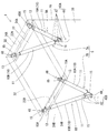
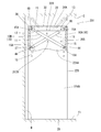
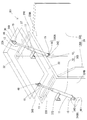
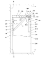
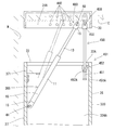
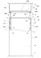
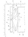
- FIG. 1 It is a partial cross section schematic diagram which shows roughly the article with a fall prevention device of Embodiment 1. It is a perspective view which shows a part of article
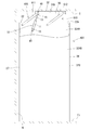
- FIG. 2 It is a partial cross section schematic diagram which shows roughly the article with a fall prevention device of Embodiment 2. It is a perspective view which shows a part of article
- FIG. It is a partial cross section schematic diagram which shows roughly the article with a fall prevention device of Embodiment 3. It is a perspective view which shows a part of article
- FIG. 5 is a schematic cross-sectional view of a part of an article with a tipping prevention device of Embodiment 3. It is explanatory drawing which shows the example which changed height about the articles
- FIG. It is a partial cross section schematic diagram which shows roughly the article with a fall prevention device of Embodiment 4. In the article with a tipping prevention device of Embodiment 4, it is a schematic cross-sectional view showing a state where it is in an unfolded position. It is a partial cross section schematic diagram which shows roughly the article with a fall prevention device of Embodiment 5. It is a partial cross section schematic diagram which shows roughly the article with a fall prevention device of Embodiment 6.
- FIG. It is explanatory drawing which shows the state of the initial position of the articles
- FIG. It is explanatory drawing which shows the state of the expansion
- FIG. It is a partial cross section schematic diagram which shows roughly the article with a fall prevention device of Embodiment 7.
- FIG. It is explanatory drawing which shows the state of the initial position of the articles
- FIG. It is explanatory drawing which shows the state of the expansion
- FIG. It is a partial cross section schematic diagram which shows roughly the article with a fall prevention device of Embodiment 8.
- Embodiment 1 that embodies an article with an overturn prevention device of the present invention will be described with reference to the drawings.
- the furniture 1 disclosed in FIG. 1 includes a furniture main body 20 disposed between the installation surface Fr and the ceiling C during installation, and a plate-like contact disposed between the ceiling C and the furniture main body 20 during installation. It has the member 30 and the action
- the operation unit 5 includes a plurality of dampers 10, and each of the dampers 10 is connected to the furniture body 20 at one end, and the contact member 30 is connected to the other end. As disclosed in the solid line in FIG. 1, the damper 10 is in a contracted state when the abutting member 30 is disposed at an initial position close to the furniture body 20 side.
- movement part 5 moves the contact member 30 to the expansion
- the direction orthogonal to the installation surface Fr is the vertical direction of the furniture 1, and the installation surface Fr is a horizontal plane orthogonal to the vertical direction.
- the vertical direction is the vertical direction.
- the predetermined direction orthogonal to the vertical direction is the width direction, and the direction orthogonal to the vertical direction and the width direction is the front-rear direction.
- the longitudinal direction of the side wall portions 24A and 24B is the vertical direction.
- a pair of side wall part 24A, 24B which comprises the furniture main body 20 is arrange
- the direction in which 24B faces is the width direction.
- the furniture body 20 has a rectangular outer diameter when viewed in plan, and has a longitudinal direction when the furniture body 20 is viewed in plan (a rectangular outer shape when viewed in plan).
- the direction of the long side) can be the width direction.
- the transversal direction when the furniture body 20 is viewed in plan can be the front-rear direction.
- the outer wall part (outer part) of the furniture main body 20 and the contact member 30 is notionally shown with the dashed-two dotted line.
- FIG. 1 shows an example of the installed state of the furniture 1.
- the furniture body 20 is placed on an installation surface Fr (for example, an indoor floor surface) with the back portion 27 facing the wall W.
- the furniture body 20 may be tilted particularly in the front-rear direction (left-right direction in FIG. 1) due to a shake such as an earthquake. Therefore, in the furniture 1, the operation unit 5 and the contact member 30 function as a fall prevention device.
- the furniture main body 20 has a rectangular parallelepiped shape, and an accommodation space is formed inside the front and rear and left and right sides of the front and rear portions 26 and 27 and a pair of side wall portions 24A and 24B that face each other in the width direction. Composed.
- the furniture main body 20 is provided with an upper wall portion 22 at an upper end portion and a lower wall portion 28 (bottom wall portion) at a lower end portion, and has a box shape as a whole.
- the furniture body 20 has, for example, a structure in which a part or all of the front surface portion 26 can be opened and closed or a structure that is always open, and has a structure that can store clothes, accessories, and the like.
- the furniture main body 20 shown here is merely an example, and various known furniture structures can be employed.
- the operation unit 5 includes damper sets 7A and 7B, and each of the damper sets 7A and 7B includes two dampers 10. All the dampers 10 constituting the damper sets 7A and 7B have the same structure.
- the damper 10 includes a cylinder 11, a rod guide (not shown), a piston (not shown), a rod (rod) 13, and two joints 15 provided at both ends.
- the cylinder 11 has a bottomed cylindrical shape.
- the rod guide seals the opening of the cylinder 11.
- the piston is slidably inserted into the cylinder 11.
- the rod 13 has a base end connected to the piston. Further, the rod 13 is inserted through the rod guide, and the tip side protrudes to the outside of the cylinder 11.
- the cylinder 11 encloses hydraulic oil and compressed gas (gas).
- Each joint portion 15 is formed by bending a flat metal fitting. Each joint portion 15 is connected to the bottom of the cylinder 11 and the tip of the rod 13.
- Each joint portion 15 is formed with a through-hole portion 15 ⁇ / b> A penetrating in a direction orthogonal to the axis of the damper 10.
- a connecting tool 44 or a connecting tool 48 described later is inserted into the through-hole portion 15A.
- All the dampers 10 constituting the damper sets 7A and 7B are pressure dampers in which the damping force generated during the extension operation is smaller than the damping force generated during the contraction operation.
- the extension operation of the damper 10 means an operation in which the protruding length of the rod 13 from the cylinder 11 and the length of the damper 10 become longer.
- the contraction operation of the damper 10 means an operation in which the protruding length of the rod 13 from the cylinder 11 and the length of the damper 10 become shorter.
- the expansion force of the compressed gas sealed in the cylinder 11 works in the extending direction.
- the mechanism (mechanism) in which the damping force of the damper 10 is generated is a well-known structure, and will not be described.
- the cylinder 11 is partitioned into a rod-side pressure chamber in which the base end portion of the rod 13 is housed and an anti-rod-side pressure chamber by a piston inside.
- the piston is formed with an orifice which is a throttle valve for communicating between the two pressure chambers.
- the orifice functions as a damping force generator that generates a damping force by applying resistance to the flow of hydraulic oil between the rod-side pressure chamber and the non-rod-side pressure chamber accompanying the expansion / contraction operation of the damper 10.
- the piston is formed with a communication passage that communicates between the pressure chambers via a check valve.
- the check valve allows the flow of hydraulic oil from the rod side pressure chamber to the anti rod side pressure chamber, and prevents the reverse flow. For this reason, when the damper 10 is extended, the flow path of the hydraulic oil from the rod-side pressure chamber to the anti-rod-side pressure chamber becomes a path between the orifice and the communication path. On the other hand, in the damper 10, during the contracting operation, the flow path of the hydraulic oil from the non-rod side pressure chamber to the rod side pressure chamber is only the orifice. For this reason, the damping force generated during the extension operation of the damper 10 is smaller than the damping force generated during the contraction operation.
- the contact member 30 includes a top plate portion 32 that contacts the ceiling at the time of installation, and side plate portions 34 ⁇ / b> A and 34 ⁇ / b> B that fall from the top plate portion 32. Form and the box-shaped form which the lower side opened.
- the top plate portion 32 of the contact member 30 is, for example, approximately the same size as the upper wall portion 22 of the furniture body 20, and the top plate portion 32 is in the initial position when the damper 10 contracts as shown in FIG. 2. Is arranged so as to entirely cover the upper surface of the upper wall portion 22.
- two damper sets 7 ⁇ / b> A and 7 ⁇ / b> B are attached to the contact member 30 and the furniture body 20.
- a damper set 7 ⁇ / b> A composed of a pair of dampers 10 is attached to one side in the width direction of the furniture body 20 and the contact member 30 (right side when viewed from the front in the example of FIG. 2).
- a damper set 7 ⁇ / b> B composed of a pair of dampers 10 is attached to the other side in the width direction of the furniture body 20 and the contact member 30 (left side when viewed from the front in the example of FIG. 2).
- the side plate portions 34 ⁇ / b> A and 34 ⁇ / b> B provided at both ends in the width direction of the contact member 30 have one end portion (upper end portion) in each damper 10 of the two damper sets 7 ⁇ / b> A and 7 ⁇ / b> B. Connected.
- Each damper 10 of the damper set 7A is connected in such a configuration that the upper end portion thereof can rotate about the rotation axis in the width direction with respect to the side plate portion 34A.
- one damper 10 ⁇ / b> A corresponds to an example of a front damper, and the one damper 10 ⁇ / b> A has a connection position with the contact member 30 before a connection position with the furniture body 20.
- the other damper 10 ⁇ / b> B corresponds to an example of a rear damper, and the other damper 10 ⁇ / b> B has a connection position with the contact member 30 behind the connection position with the furniture body 20. More specifically, the connection position between one damper 10A and the side plate portion 34A is a front position from the connection position between the other damper 10B and the side plate portion 34A.
- Each damper 10 of the damper set 7B is connected in such a configuration that the upper end portion thereof can rotate about the rotation axis in the width direction with respect to the side plate portion 34B.
- one damper 10A corresponds to an example of a front damper, and one damper 10A has a connection position with the contact member 30 before a connection position with the furniture body 20.
- the other damper 10 ⁇ / b> B corresponds to an example of a rear damper, and the other damper 10 ⁇ / b> B has a connection position with the contact member 30 behind the connection position with the furniture body 20.
- connection position between one damper 10A and the side plate portion 34B is a front position than the connection position between the other damper 10B and the side plate portion 34B.
- a connecting tool 48 is inserted into a through hole 15 ⁇ / b> A of the joint portion 15 provided at the upper end, and the connecting tool 48 prevents the connecting member 48 from coming off. It is fixed.
- the connection tool 48 is constituted by, for example, a bolt, and is fixed by being screwed at a predetermined depth with respect to one of the side plate portions 34A, 34B, for example.
- the other end portions (lower end portions) of the dampers 10 of the two damper sets 7 ⁇ / b> A and 7 ⁇ / b> B are connected to the side wall portions 24 ⁇ / b> A and 24 ⁇ / b> B of the furniture body 20.
- Both dampers 10 of the damper set 7A are connected in such a configuration that the lower end portions can rotate with respect to the side wall portion 24A.
- the connecting position of one damper 10A and the side wall part 24A is the same as the connecting position of the other damper 10B and the side wall part 24A in the front-rear direction, and both dampers 10A and 10B have a common position. It rotates around the rotation axis.
- joint portions 15 connected to the bottom portions of the respective cylinders 11 are provided at the lower end portions of both dampers 10 constituting the damper set 7 ⁇ / b> A, and through holes formed in the joint portions 15.
- the shaft member of the connector 44 is inserted through the portion 15A.
- the coupling tool 44 is inserted into the through-hole portion 15A of the joint portion 15 and is inserted into the through-hole portion 42 of the side wall portion 24A and fixed, and the shaft member is opposite to the insertion side. And a retaining portion disposed at the end.
- the cross section of the shaft member is shown.
- the through-hole portion 42 may be configured by a female screw structure
- the connector 44 may be a bolt that is screwed to the through-hole portion 42 to a predetermined depth.
- the structure is not limited to this structure, and other structures may be adopted as long as the joint part 15 is not detached from the connector 44 inserted into the through-hole part 42.
- the damper set 7A is configured such that both dampers 10 are rotatably connected to the side wall portion 24A in such a configuration, and can be rotated along a plane direction orthogonal to the width direction.
- Both dampers 10 of the damper set 7B are connected in such a configuration that the lower ends thereof can rotate around the rotation axis in the width direction with respect to the side wall 24B.
- the connecting position of one damper 10A and the side wall part 24B is the same as the connecting position of the other damper 10B and the side wall part 24B in the front-rear direction, and both dampers 10A and 10B have a common position. It rotates around the rotation axis.
- joint portions 15 are respectively provided at lower ends of both dampers 10 constituting the damper set 7 ⁇ / b> B, and the shaft member of the connector 44 is connected to both through-hole portions 15 ⁇ / b> A formed in both joint portions 15. Is inserted.
- the structure in which the lower end portion of the damper set 7B is fixed to the side wall portion 24B by the connecting tool 44 is the same as the structure in which the lower end portion of the damper set 7A is fixed to the side wall portion 24A by the connecting tool 44.
- Each of the damper sets 7A and 7B configured as described above has an interval expanding portion in which the front-rear interval between the one damper 10A and the other damper 10B increases as the contact member 30 is approached.
- the entire damper set 7A is configured as an interval widening portion 9A, and the lower end portion of one damper 10A and the lower end portion of the other damper 10B overlap in the width direction.
- the part on the upper side is the interval enlarged portion 9A.
- the front-rear interval between the one damper 10A and the other damper 10B increases as the contact member 30 is approached.
- the damper set 7B is configured as an interval expanding portion 9B, and the lower end portion of one damper 10A and the lower end portion of the other damper 10B overlap in the width direction, and above the overlapping portion.
- part of the side becomes the space
- the front-rear interval between the one damper 10A and the other damper 10B increases as the contact member 30 is approached.
- openings 22 ⁇ / b> A and 22 ⁇ / b> B penetrating vertically are formed in the upper wall portion 22 of the furniture body 20.
- the openings 22A and 22B have a long hole shape that is long in the front-rear direction.
- Both dampers 10 of the damper set 7 ⁇ / b> A are connected to the inner wall surface of the side wall part 24 ⁇ / b> A and inserted through the opening 22 ⁇ / b> A of the upper wall part 22, and straddle the interior and the exterior of the furniture body 20.
- Both dampers 10 of the damper set 7 ⁇ / b> B are connected to the inner wall surface of the side wall portion 24 ⁇ / b> B and inserted through the opening 22 ⁇ / b> B of the upper wall portion 22, and straddle the interior and the exterior of the furniture body 20.
- the furniture 1 includes adjustment units 40A and 40B (adjustment units on the article main body side) that adjust the connection position of the damper 10 in the furniture main body 20.
- One side in the width direction of the furniture body 20 is provided with an adjustment unit 40A that adjusts the connecting position of the dampers 10 that constitute the damper set 7A (specifically, the height at which the lower ends of the dampers 10 are attached).
- an adjustment portion 40B that adjusts the connecting position of the dampers 10 that constitute the damper set 7B (specifically, the height at which the lower ends of the dampers 10 are attached).
- Each of the adjusting portions 40A and 40B is configured by a plurality of through-hole portions 42 arranged in the vertical direction at intervals, and a connecting tool 44 fixed so as to be inserted through the through-hole portion 42.
- the adjustment portion 40A switches both the dampers in the damper set 7A by switching among the plurality of through-hole portions 42 arranged in the vertical direction as the attachment target of the connector 44 inserted into the lower end portion of the damper set 7A.
- the height of the lower end of 10 can be changed.
- the adjustment portion 40B switches the hole to be attached to the connector 44 inserted into the lower end of the damper set 7B among the plurality of through-hole portions 42 arranged vertically, thereby setting the damper set 7B.
- the height of the lower end portions of both dampers 10 can be changed.
- the pair of dampers 10 are connected to the furniture body 20 at the same connection position (the connection positions where the vertical positions and the front and rear positions of both through-hole portions 15A are the same). It is the composition which becomes. More specifically, the lower end portions of the pair of dampers 10 are connected by a common connecting tool 44, and both through-hole portions 15A of both dampers 10 through which the connecting tool 44 is inserted have a position in the front-rear direction and a vertical direction. Are positioned so as to be the same position.
- the contact member 30 When installing the furniture 1 configured in this way, first, as shown by a solid line in FIG. 1, the contact member 30 is maintained near the initial position close to the furniture body 20 side. In this configuration, the position where the contact member 30 is closest to the furniture body 20 is the initial position. In the example of FIG. 1, the contact member 30 contacts the upper wall portion 22 of the furniture body 20 at the initial position. It is like that.
- the contact member 30 When the contact member 30 is in the initial position as shown in FIG. 1, all the dampers 10 are in the contracted state. At this time, an urging force for continuously moving the contact member 30 upward by the damper 10 is applied. Therefore, in order to maintain the contact member 30 in the initial position, it is necessary to keep the furniture body 20 and the contact member 30 close to each other by an operator's operation or a tool.
- a member such as a string or a wire may be fixed to each of the furniture body 20 and the abutting member 30 to keep these intervals narrow.
- the contact member 30 may be maintained in the state of being disposed at the initial position. After the furniture 1 is placed on the installation surface Fr with the contact member positioned at the initial position in this way, the force applied to maintain the contact member 30 at the initial position is released. Then, the damper 10 is extended by the expansion force of the compressed gas sealed in the cylinder 11, and the contact member 30 can be brought into contact with the ceiling C as shown by the two-dot chain line in FIG.
- the contact member 30 is disposed between the furniture body 20 and the ceiling C at the time of installation, and the furniture body 20 and the contact member 30 are extended by the extension of the damper 10 of the operation unit 5.
- this furniture 1 can be stably installed in the form of placing on the installation surface Fr and pressing the ceiling C.
- the damper 10 interposes in the form connected with each of the furniture main body 20 and the contact member 30, at the time of installation, a damping force can be generated by the expansion-contraction operation
- the furniture 1 is integrally connected to the furniture body 20, the contact member 30, the damper 10, and the like, and these can be managed integrally, so that the management burden can be reduced.
- the damper 10 can be connected and positioned in advance to the furniture body 20 and the abutting member 30, so that the installation work or positioning work of the damper 10 with respect to the furniture body 20 can be performed. The burden can be reduced.
- one damper 10A front damper
- the damper 10B rear damper
- the furniture body 20 is in the front-rear direction (the direction in which it easily falls). Even if it leans to either, it can attenuate effectively.
- Such an effect can also occur when the furniture 1 is installed in a state where the furniture body 20 is adjacent to the wall W as shown in FIG. 1, but the furniture body 20 is not adjacent to an external wall, so-called. It becomes prominent when it is installed as an “islanding state”.
- Convention general furniture is placed in an “islanding state”, there is no support by the external wall, so there is a possibility of tilting to one side or the other side of the tipping direction (the direction in which the tipping is easy to place) Because of this, there was no choice but to place it in an unstable state.
- damper sets 7A and 7B which are a pair of dampers 10, are respectively attached to both sides of the furniture body 20 in the width direction.
- Each of the damper sets 7A and 7B is provided with interval expanding portions 9A and 9B that increase as the front-rear interval between one damper 10A and the other damper 10B approaches the contact member 30.
- the connection position between one damper 10A and the contact member 30 is the front position with respect to the connection position between the other damper 10B and the contact member 30. It has become.
- the connecting position between one damper 10A and the furniture body 20 is the same as the connecting position between the other damper 10B and the furniture body 20 in the front-rear direction. In this way, if the damper sets 7A and 7B are attached in an intersecting state (at least partially overlapped), one damper 10A is tilted by one side in the front-rear direction, and the other damper 10B is placed on the other side in the front-rear direction.
- the contact member 30 can be supported in a tilted manner.
- the furniture body 20 includes side wall portions 24A and 24B and an upper wall portion 22. In the upper wall portion 22, openings 22A and 22B penetrating vertically are formed.
- the damper 10 is connected to one of the inner wall surfaces of the side wall portions 24A and 24B and is inserted through one of the opening portions 22A and 22B. According to this configuration, the interior of the furniture body 20 can be used as an arrangement space for the damper 10. When the damper 10 is contracted, the contact member 30 can be placed closer to the furniture body 20 and arranged more compactly.
- the dampers 10 are respectively connected to both ends of the furniture body 20 in the width direction.
- the plurality of dampers 10 are attached so as to be separated from each other in the width direction, among the areas between the contact member 30 and the furniture main body 20, areas between the dampers arranged on both sides in the width direction are installed. Widely secured. Therefore, such a widely secured area can be used effectively as a storage space or the like.
- the furniture 1 of this configuration is configured such that a plurality of dampers 10 are connected to the furniture body 20 at the same connection position on both sides in the width direction. And the furniture 1 is equipped with adjustment part 40A, 40B (adjustment part by the side of goods) which adjusts the connection position of the some damper 10 in the furniture main body 20.
- FIG. the coupling position of the damper 10 in the furniture body 20 can be set to a more desirable coupling position according to the environment in which the article is installed.
- the plurality of dampers 10 are connected at the same connection position at any position adjusted by the adjustment units 40A and 40B, compared to a structure in which the plurality of dampers 10 are individually adjusted and fixed. The number of parts can be reduced and workability can be improved.
- the height of the lower end portion of the damper 10 can be adjusted by the adjustment portions 40A and 40B (the adjustment portion on the article side). Therefore, the appropriate height range of the contact member 30 can be switched according to the distance between the installation surface and the ceiling without preparing a large number of dampers having different lengths.
- Embodiment 2 will be described with reference to FIGS. 3 and 4.
- the furniture 201 of the second embodiment shown in FIG. 3 and FIG. 4 is configured such that the operation unit 205, the adjustment units 240A, 240B, 240C, and 240D, and the side wall portions 224A and 224B are the operation unit 5 and the adjustment units 40A and 40B of the first embodiment.
- the side wall portions 24A and 24B are different. Since the other parts have the same structure as that of the first embodiment and have the same functions, the same reference numerals as those of the first embodiment are given and detailed description thereof is omitted.
- the furniture 201 includes a furniture main body 220 disposed between the installation surface Fr and the ceiling C during installation, and a plate-like contact member 30 disposed between the ceiling C and the furniture main body 220 during installation.
- an operation unit 205 which corresponds to an example of the article with the overturn prevention device of the present invention.
- the operation unit 205 includes a plurality of dampers 10, and each of the dampers 10 is connected to the furniture body 220 at one end, and the contact member 30 is connected at the other end.
- the structure of each damper 10 is the same as that of the first embodiment.
- the damper 10 is in a contracted state when the abutting member 30 is disposed at an initial position close to the furniture body 220 side.
- the operation unit 205 moves the contact member 30 to the deployed position away from the furniture body 220 from the initial position in accordance with the extension of the damper 10, It operates to contact the ceiling C.
- a damper set 207 ⁇ / b> A constituted by a pair of dampers 10 is attached to one side in the width direction of the furniture main body 220 and the contact member 30 (right side when viewed from the front in the example of FIG. 4).
- a damper set 207 ⁇ / b> B composed of a pair of dampers 10 is attached to the other side in the width direction of the furniture body 220 and the contact member 30 (left side when viewed from the front in the example of FIG. 4).
- the side plate portions 34A and 34B provided at both ends in the width direction of the contact member 30 have one end portion (upper end portion) in each damper 10 of the two damper sets 207A and 207B. It is connected so that it can rotate.
- the other end portions (lower end portions) of the dampers 10 of the two damper sets 207A and 207B are rotatably connected to the side wall portions 224A and 224B of the furniture body 20.
- the connecting position between the one damper 10A and the side plate portion 34A is in front of the connecting position between the other damper 10B and the side plate portion 34A.
- the connection position of one damper 10A and the side wall part 224A is behind the connection position of the other damper 10B and the side wall part 224A. That is, the damper set 207A has a structure in which one damper 10A and the other damper 10B intersect when viewed from the side. In the damper set 207B, the connecting position between the one damper 10A and the side plate portion 34B is in front of the connecting position between the other damper 10B and the side plate portion 34B. And the connection position of one damper 10A and the side wall part 224B is behind the connection position of the other damper 10B and the side wall part 224B. That is, the damper set 207B also has a structure in which one damper 10A and the other damper 10B intersect when viewed from the side.
- the cylinder 11 of one damper 10A and the cylinder 11 of the other damper 10B partially overlap in the width direction, and a portion above the overlapped portion is an interval expanding portion 209A.
- the front-rear interval between the one damper 10 ⁇ / b> A and the other damper 10 ⁇ / b> B increases as the contact member 30 is approached.
- the cylinder 11 of one damper 10A and the cylinder 11 of the other damper 10B partially overlap in the width direction, and a portion above the overlapped portion is an interval expanding portion 209B. It has become.
- the front-rear interval between the one damper 10 ⁇ / b> A and the other damper 10 ⁇ / b> B increases as the contact member 30 is approached.
- the adjustment unit 240A switches the hole to be attached to the connector 44 inserted into the lower end of one damper 10A in the damper set 207A among a plurality of through-holes arranged vertically.
- the height of the lower end portion of the damper 10A can be changed.
- the adjustment portion 240B switches the hole to be attached to the connector 44 inserted into the lower end portion of the other damper 10A in the damper set 207A among the plurality of through-hole portions arranged vertically.
- the height of the lower end portion of the damper 10B can be changed.
- the adjustment portion 240C switches the hole to be attached to the connector 44 inserted into the lower end portion of one damper 10A in the damper set 207B among a plurality of through-hole portions arranged vertically.
- the height of the lower end portion of the damper 10A can be changed.
- the adjustment portion 240D switches the hole to be attached to the connector 44 inserted into the lower end portion of the other damper 10A in the damper set 207D among a plurality of through-hole portions arranged vertically.
- the height of the lower end portion of the damper 10B can be changed.
- the contact member 30 is maintained near the initial position close to the furniture body 20 side, and the furniture 1 is placed on the installation surface Fr in that state. Thereafter, when the force applied to maintain the contact member 30 at the initial position is released, the damper 10 expands due to the expansion force of the compressed gas enclosed in the cylinder 11, as shown by a two-dot chain line in FIG. 3. The contact member 30 can be brought into contact with the ceiling C. Even with the configuration of the furniture 201 as described above, the same effect as that of the furniture 1 of the first embodiment can be obtained.
- Embodiment 3 will be described with reference to FIGS.
- the furniture 301 of the third embodiment shown in FIG. 5 and the like has a point that the operation unit 5 is changed to the operation unit 305, a point that the angle regulation units 371 and 372 are provided, and a point that the through hole part 42 is changed to the through hole part 342.
- the other points are the same as the furniture 1 of the first embodiment. Therefore, about the part similar to the furniture 1 of Embodiment 1, the code
- the furniture 301 according to the third embodiment is arranged between the furniture main body 320 arranged between the installation surface Fr and the ceiling C at the time of installation, and between the ceiling C and the furniture main body 320 at the time of installation.
- the plate-like contact member 30 and the operating unit 305 are provided.
- the operation unit 305 includes a plurality of dampers 10, and each damper 10 is connected to the furniture main body 320 at one end, and the contact member 30 is connected to the other end.
- the structure of each damper 10 is the same as that of the first embodiment. As disclosed in the solid line in FIG. 5, the damper 10 is in a contracted state when the abutting member 30 is disposed at an initial position close to the furniture body 320 side.
- the operation unit 305 moves the contact member 30 to the unfolded position away from the furniture body 320 from the initial position in accordance with the extension of the damper 10, It operates to contact the ceiling C.
- the furniture body 320 has the same configuration as that of the furniture body 20 of the first embodiment except for the side wall portions 324A and 324B. As shown in FIG. Opening portions 22A and 22B penetrating through are formed in a long hole structure extending in the front-rear direction.
- the structure of the front-surface part 26 is actualized, and in this example, the door part which opens and closes the opening part (part opened to the front side) formed in the front surface of the furniture main body 320.
- a front surface portion 26 is configured as 26A and 26B.
- the dampers 10 are connected one by one to both ends in the width direction of the furniture body 320 and the contact member 30.
- An end (upper end) on one side of the damper 10 is rotatably connected to the side plate portion 34A provided on one side in the width direction of the abutting member 30, and the inner side of the side wall 324 ⁇ / b> A of the furniture body 20.
- On the wall surface side the other end (lower end) of the damper 10 is rotatably connected.
- An end (upper end) on one side of another damper 10 is rotatably connected to the side plate part 34B provided on the other side in the width direction of the contact member 30, and the side wall part 324 ⁇ / b> B of the furniture body 20.
- the other end portion (lower end portion) of the damper 10 is rotatably connected to the inner wall surface side.
- the damper 10 connected to the side plate portion 34 ⁇ / b> A and the side wall portion 324 ⁇ / b> A is inserted through the opening 22 ⁇ / b> A of the upper wall portion 22 and is disposed across the interior and the exterior of the furniture body 320. Yes.
- the damper 10 connected to the side plate part 34B and the side wall part 324B is inserted through the opening 22B of the upper wall part 22, and is disposed across the interior and the exterior of the furniture body 320.
- the furniture 301 is also provided with adjustment units 340A and 340B (adjustment units on the article main body side) that adjust the connection position of the lower end of each damper 10 in the furniture main body 320.
- Each of the adjusting portions 340A and 340B includes a plurality of through-hole portions 342 arranged in the vertical direction at intervals, and a connector 44 that is fixed so as to be inserted through the through-hole portion 342.
- the adjustment portion 340A switches the hole to be attached to the connector 44 inserted into the lower end portion of the damper 10 on one side in the width direction among the plurality of through-hole portions 342 arranged in the vertical direction. The height of the lower end of 10 can be changed.
- the adjustment portion 340B switches the hole to be attached to the connector 44 inserted into the lower end portion of the damper 10 on the other side in the width direction among the plurality of through-hole portions 342 arranged in the vertical direction, so that the other damper
- the height of the lower end of 10 can be changed.
- the connection tool 44 inserted into the lower end portion of the damper 10 is attached so as to be fixed to the third hole from the top.
- the connecting tool 44 inserted into the lower end portion of the damper 10 is attached so as to be fixed to the uppermost through-hole portion 342, and than the configuration of FIGS.
- the lower end portion of the damper 10 is arranged high.
- the furniture 301 is provided with angle restricting portions 371 and 372 for restricting the inclination angles of the dampers 10 arranged on both sides in the width direction. It can be arranged at an inclination angle.
- the angle restricting portion 371 on one side in the width direction is fixed to the back surface portion 27 so as to extend forward from the inner wall surface of the back surface portion 27 on the rear side of the damper 10 on one side in the width direction.
- the angle restricting portion 371 abuts on the damper 10 when the inclination angle with respect to the vertical direction of the damper 10 on one side in the width direction becomes an allowable minimum angle, and restricts the damper 10 from rising further.
- the damper 10 on one side in the width direction rotates around the rotation axis in the width direction around the shaft member of the connector 44, but is restricted so that the inclination angle with respect to the vertical direction is not less than the minimum angle. Further, the damper 10 on one side in the width direction is restricted so as to abut against the front end portion of the opening 22A when the inclination angle with respect to the vertical direction reaches a predetermined maximum angle, and does not tilt further.
- the angle restricting portion 372 on the other side in the width direction is fixed to the back portion 27 so as to extend forward from the inner wall surface of the back portion 27 on the rear side of the damper 10 on the other side in the width direction.
- the angle restricting portion 372 abuts on the damper 10 when the inclination angle with respect to the vertical direction of the damper 10 on the other side in the width direction becomes an allowable minimum angle, and restricts the damper 10 from rising further.
- the damper 10 on the other side in the width direction rotates around the rotation axis in the width direction around the shaft member of the connector 44, but is restricted so that the inclination angle with respect to the vertical direction is not less than the minimum angle.
- the damper 10 on the other side in the width direction is regulated so as to abut against the front end portion of the opening 22B when the angle of inclination with respect to the vertical direction reaches a predetermined maximum angle, and does not tilt further.
- the dampers 10 on both sides in the width direction are restricted so that the inclination angle with respect to the vertical direction is within the range from the minimum angle to the maximum angle.
- the abutment member 30 When installing the furniture 301 having this configuration, the abutment member 30 may be maintained near the initial position close to the furniture body 20 and the furniture 1 may be placed on the installation surface Fr. When the force applied to maintain the contact member 30 at the initial position is released after the placement, the damper 10 expands due to the expansion force of the compressed gas enclosed in the cylinder 11, and FIG. The abutting member 30 can be brought into contact with the ceiling C as indicated by a two-dot chain line.
- the furniture 401 of the fourth embodiment shown in FIG. 9 and the like includes all the configurations of the third embodiment and further adds a new configuration. Specifically, a guide part 450, a spacing restriction part 451A, and an adjustment part 480 are added to the furniture 301 of the third embodiment shown in FIG. Therefore, in the furniture 401, about the part similar to the furniture 301 of Embodiment 3, the code
- the furniture 401 includes a furniture main body 320 disposed between the installation surface Fr and the ceiling C during installation, and a plate disposed between the ceiling C and the furniture main body 320 during installation.
- the furniture main body 320, the contact member 30, and the operation unit 305 have the same configuration as that of the third embodiment and function in the same manner.
- the angle restricting portion only one angle restricting portion 371 is shown in FIG. 9, but it has the same configuration as the angle restricting portions 371 and 372 shown in FIG.
- the operation unit 305 has the same configuration as that of FIG.
- each damper 10 is connected to the furniture body 320 at one end and to the contact member 30 on the other side. The ends are connected.
- the structure of each damper 10 is the same as that of the first embodiment. As shown in FIG. 9, the damper 10 is contracted when the abutting member 30 is disposed at the initial position near the furniture body 320. Then, the operation unit 305 moves the contact member 30 to the unfolded position farther from the furniture body 320 than the initial position in accordance with the extension of the damper 10 as shown in FIG. Operate.
- the furniture 401 includes a guide portion 450 that regulates the horizontal movement range of the contact member 30 when the damper 10 expands and contracts.
- the guide part 450 includes a linear shaft member 451 extending linearly and a guide part 452 for guiding the shaft member 451 in the vertical direction.
- a joint portion 455 similar to the joint portion 15 is provided at the upper end portion of the shaft member 451, and the joint portion 455 is rotatably connected to the side plate portion 34A of the contact member 30.
- the lower end portion of the shaft member 451 is provided with a flange-shaped interval regulating portion 451A that projects outward from a main body portion 451B (a portion that fits in a through-hole portion 452A described later) of the shaft member 451. .
- the guide part 452 is fixed to the inner wall surface of the side wall part 324 of the furniture body 320, and a through-hole part 452A extending in the vertical direction is formed.
- the through-hole portion 452A is slidably fitted to the main body portion 451B of the shaft member 451, and guides the main body portion 451B up and down while maintaining the longitudinal direction of the main body portion 451B in the vertical direction.
- the shaft member 451 moves up and down while the guide portion 452 maintains the position in the front-rear direction and the width direction of the shaft member 451. Therefore, the contact member 30 connected to the shaft member 451 is guided up and down in a state in which the position in the front-rear direction and the position in the width direction are maintained (that is, the movement in the horizontal direction is restricted). Become.
- the contact member 30 can be arranged more compactly without being largely removed from the furniture body 320 in the horizontal direction when the damper 10 is contracted. Further, when the damper 10 is extended, the contact member 30 can be moved away from the furniture body 320 without largely removing it in the horizontal direction.
- interval control part 451A controls that the space
- the furniture 401 is provided with an adjustment unit 480 (adjustment unit on the contact member side) that adjusts the connecting position of the damper 10 in the contact member 30.
- the adjustment portion 480 is configured by a plurality of through-hole portions 442 formed so as to be arranged in the front-rear direction at intervals in the side plate portion 34A, and a connector 48 that is fixed so as to be inserted into the through-hole portion 442.
- the position of the upper end portion of the damper 10 is switched by switching the hole portion to be attached to the connecting portion 48 inserted into the upper end portion of the damper 10 among the plurality of through hole portions 442 arranged in the front and rear direction. Can be changed back and forth. As a result, the height of the upper end portion of the damper 10 can be changed.
- the connector 48 inserted into the upper end portion of the damper 10 is attached so as to be fixed to the through hole portion 442 at the foremost position.
- the attachment position is changed so that the coupling tool 48 inserted in the upper end part of the damper 10 may be fixed to the 3rd through-hole part 442 from the front.
- the extension of the rod 13 is approximately the same as that in the example indicated by the solid line, but the height of the upper end of the damper 10 becomes higher because the damper 10 rises more.
- FIG. 9 the structure of the width direction other side is also the same. That is, a through-hole part similar to the through-hole part 442 is also formed in the side plate part 34B on the other side in the width direction (see FIG. 6 and FIG. 7) in the front-rear direction, and an adjustment part similar to the adjustment part 480 is provided. It is configured. And the attachment position of the upper end part of the damper 10 (refer FIG. 6, FIG. 7) of the other side of the width direction can be changed. Further, a guide portion similar to the guide portion 450 is provided also on the other side in the width direction, and the horizontal movement of the contact member 30 is also restricted on the other side in the width direction. Even with the configuration of the furniture 401 as described above, the same effect as that of the furniture 301 of the third embodiment can be obtained.
- Embodiment 5 will be described with reference to FIG.
- the furniture 501 of the fifth embodiment shown in FIG. 11 is different from the abutting member 30 of the third embodiment only in the configuration of the abutting member 530, and the configuration other than the abutting member is the same as that of the third embodiment. Therefore, components other than the contact member are denoted by the same reference numerals as those in the third embodiment, and detailed description thereof is omitted.
- the furniture 501 includes a furniture main body 320 disposed between the installation surface Fr and the ceiling C at the time of installation, and a box disposed between the ceiling C and the furniture main body 320 at the time of installation.
- a contact member 530 having a shape, an operating portion 305, and angle restricting portions 371 and 372 are provided.
- the furniture main body 320, the operation unit 305, and the angle regulation units 371 and 372 have the same configuration as that of the third embodiment and function in the same manner.
- the operation unit 305 has the same configuration as that of FIG. 6 and includes a plurality of dampers 10, and each damper 10 is connected to the furniture body 320 at one end and to the contact member 30 on the other side. The ends are connected.
- each damper 10 is the same as that of the first embodiment.
- the damper 10 is contracted.
- the operation unit 305 moves the contact member 530 to a deployment position farther from the furniture body 320 than the initial position in accordance with the extension of the damper 10 as shown in FIG. Operate.
- the contact member 530 includes a box-shaped portion 530A configured in a box shape.
- the box-shaped portion 530A has, for example, a structure in which the front surface portion is always open or a structure that can be opened and closed, and the inside is configured as a storage space.
- a member 530B having the same configuration as that of the contact member 30 of the third embodiment is provided at the bottom of the box-shaped portion 530A.
- the member 530B includes a plate-like portion 532 similar to the top plate portion 32 (FIG.
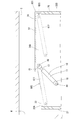
- the furniture 601 of the sixth embodiment shown in FIGS. 12 to 14 is mainly different from the third embodiment in that a link portion 603 is provided. Therefore, components other than the link unit 603 are denoted by the same reference numerals as those in the third embodiment, and detailed description thereof is omitted.
- the mounting position of the damper 10 is slightly different from that of the third embodiment, but the mounting position can be changed variously, and the mounting structure of the damper 10 can be the same as that of the third embodiment. it can.
- the furniture 601 of the sixth embodiment includes a furniture main body 320 disposed between the installation surface Fr and the ceiling C during installation, and a plate disposed between the ceiling C and the furniture main body 320 during installation.
- the abutting member 30 and an operating part 605 are provided.
- the structure of the plurality of dampers 10 (the illustration of the damper on the other side in the width direction is omitted) is the same as that of the third embodiment, and a link unit 603 is added to this structure.
- Each damper 10 has one end connected to the furniture body 320 and the other end connected to the contact member 30.
- the structure of each damper 10 is the same as that of the first embodiment.
- the operation unit 605 moves the contact member 30 to a deployment position farther from the furniture body 320 than the initial position in accordance with the extension of the damper 10 as shown in FIG. Operate.
- the operation unit 605 includes a link unit 603 that connects the contact member 30 and the furniture body 320 and is displaced according to the expansion and contraction of the damper 10.
- the link portion 603 both end portions of the pair of link members 611 and 612 are rotatably connected to the side wall portion 324A of the furniture body 320 and the side plate portion 34A of the contact member 30, respectively.
- the link members 611 and 612 are rotated while the pair of link members 611 and 612 are kept parallel to each other, and the positions of the upper ends of the link members 611 and 612 are always at the same height. It is supposed to be kept.
- the top plate part 32 of the contact member 30 connected to the link members 611 and 612 moves up and down while maintaining a horizontal state.
- the link portion 603 configured as described above tilts the damper 10 when the damper 10 is contracted as shown in FIG. 13 and guides the contact member 30 to the initial position side. Then, as shown in FIG. 14, the damper 10 rises in conjunction with the extension of the damper 10 and operates so as to guide the contact member 30 to the deployed position.
- 12 to 14 show the link portion on one side in the width direction, a similar link portion can be provided on the other side in the width direction.
- the damper 10 when the damper 10 is contracted, the damper 10 can be tilted to make the entire article compact, and at the time of installation, the link portion is operated in conjunction with the extension of the damper to automatically raise the damper. Can do. Even with such a configuration of the furniture 601, the same effect as that of the furniture 301 of the third embodiment can be obtained.
- the furniture 701 of the seventh embodiment shown in FIGS. 15 to 17 is mainly different from the third embodiment in that a link portion 703 is provided. Therefore, components other than the link unit 703 are denoted by the same reference numerals as those in the third embodiment, and detailed description thereof is omitted.
- the mounting position of the damper 10 is slightly different from that of the third embodiment, but the mounting position can be changed variously, and the mounting structure of the damper 10 can be the same as that of the third embodiment. it can.
- the furniture 701 includes a furniture main body 320 disposed between the installation surface Fr and the ceiling C during installation, and a plate disposed between the ceiling C and the furniture main body 320 during installation.
- the abutting member 30 and an operating part 705 are provided.
- each damper 10 has one end connected to the furniture body 320 and the other end connected to the contact member 30.
- the structure of each damper 10 is the same as that of the first embodiment.
- the operation unit 705 moves the contact member 30 to a deployment position farther from the furniture body 320 than the initial position in accordance with the extension of the damper 10 as shown in FIG. Operate.
- the operation unit 705 includes a link unit 703 that connects the contact member 30 and the furniture body 320 and is displaced according to the expansion and contraction of the damper 10.
- the link portion 703 In the link portion 703, four link members 711, 712, 713, 714 are connected in a diamond shape.
- the link members are connected so as to be rotatable.
- the link members 711 and 713 are rotatably connected to the side plate portion 34A of the contact member 30, and the link members 712 and 714 are rotatably connected to the side wall portion 324A of the furniture body 320.
- the link portion 703 configured in this manner tilts the damper 10 when the damper 10 is contracted as shown in FIG. 16 and guides the contact member 30 to the initial position side. Then, as shown in FIG.
- the damper 10 rises in conjunction with the extension of the damper 10 and operates so as to guide the contact member 30 to the deployed position.
- the link portion on one side in the width direction is shown, but a similar link portion can also be provided on the other side in the width direction.
- the damper 10 can be tilted when the damper 10 is contracted to make the entire article compact, and at the time of installation, the link portion can be operated in conjunction with the extension of the damper to automatically raise the damper. .
- the same effect as that of the furniture 301 of the third embodiment can be obtained.
- Embodiment 8 will be described with reference to FIG.
- the furniture 801 of the eighth embodiment shown in FIG. 18 has a structure in which a furniture main body 820 corresponding to an article main body is arranged on the upper side and a box-shaped contact member 830 is arranged on the lower side.
- symbol as Embodiment 1 is attached
- the furniture 801 according to the eighth embodiment is disposed between the furniture body 820 disposed between the installation surface Fr and the ceiling C at the time of installation, and between the installation surface Fr and the furniture body 820 at the time of installation.
- a box-shaped contact member 830 and an operating unit 805 are provided.
- each damper 10 has one end (upper end) connected to the furniture body 820 and the other end (lower end) connected to the contact member 830.
- the structure of each damper 10 is the same as that of the first embodiment.
- the contact member 830 When the contact member 830 is disposed at an initial position close to the furniture body 820 (that is, when the furniture body 820 is positioned at a lower position away from the ceiling C and close to the contact member 830) ), The damper 10 is in a contracted state. Then, the operation unit 805 moves the contact member 830 relative to the unfolded position away from the furniture body 820 from the initial position in accordance with the extension of the damper 10 as shown in FIG. Operate to pull 830 apart. By this operation, the furniture body 820 is installed so as to contact the ceiling C. With the configuration of the furniture 801 as described above, the same effect as that of the furniture 1 of the first embodiment can be obtained.
- the fall prevention device is attached to the furniture, but it may be attached to an article such as a bookcase or a refrigerator that may fall over due to shaking such as an earthquake.
- all of the plurality of dampers 10 are pressure dampers. However, all of the plurality of dampers may be dual effect dampers having the same damping force generated during the extension operation and the contraction operation. . Alternatively, any of the plurality of dampers may be an extension damper in which the damping force generated during the extension operation is larger than the damping force generated during the contraction operation.
- the damper in which the hydraulic oil and the compressed gas are sealed in the cylinder is used.
- the liquid pressure in which another liquid is sealed is used. It may be a damper or another type of damper.
- the compressed gas is sealed in the cylinder so that the expansion force of the compressed gas acts in the extension direction.
- the force acting in the extension direction may be generated by other methods.
- the article-side adjustment unit is configured with a plurality of through-holes provided in the side wall, but the present invention is not limited to this configuration.
- the part where the lower end of the damper is connected in the article body is slidable, and the height is adjusted by sliding the part where the lower end of the damper is connected up and down by a worm wheel structure or the like. May be.
- the lower end portions of the pair of dampers 10A and 10B are connected to the furniture body 20 by the common connecting tool 44 in any of the height adjusting portions 40A and 40B provided on both sides in the width direction.
- the structure connected by position was illustrated. However, it is not limited to this structure, You may be comprised so that the lower end part of a pair of damper 10A, 10B may be separately fixed by a separate connector. And also in this structure, the fixing position by each connection tool may be changeable.
- adjustment part (adjustment part on the article body side), 371, 372 ... angle regulation , 450... Guide part 450, 451 A.
Landscapes
- Engineering & Computer Science (AREA)
- General Engineering & Computer Science (AREA)
- Mechanical Engineering (AREA)
- Vibration Prevention Devices (AREA)
Abstract
物品自体に転倒防止機能を付加することができ、取付時の作業負担や管理負担を低減し得る転倒防止装置付き物品を提供する。 家具(1)は、設置時に設置面(Fr)と天井(C)との間に配置される家具本体(20)と、設置時に天井(C)と家具本体(20)との間に配置される当接部材(30)とを備える。更に、家具(1)は、家具本体(20)に一方側の端部が連結されるとともに当接部材(30)に他方側の端部が連結されるダンパ(10)を有する動作部(5)を備える。動作部(5)は、当接部材(30)が家具本体(20)側に寄った初期位置に配置される時にダンパ(10)が収縮状態となり、ダンパ(10)の伸長に応じて当接部材(30)を初期位置よりも家具本体(20)から上方に遠ざけた展開位置に移動させ、天井(C)に当接させるように動作する。
Description
本発明は転倒防止装置付き物品に関するものである。
特許文献1は従来の転倒防止装置を開示している。この転倒防止装置はダンパ(damper)と一対のベース(base)部とを備えている。ダンパは床面上に設置された家具の上面と天井との間に取り付けられている。一対のベース部はダンパの両端部の夫々を回動軸周りに回動自在に軸支している。一方のベース部は家具の上面に当接し、他方のベース部は天井に当接している。このため、この転倒防止装置は、地震等の揺れによってダンパの回動方向と平行な方向に家具が傾くと、各ベース部に対してダンパが回動軸周りに回動し、各ベース部が家具の上面と天井とに当接した状態を維持することができる。よって、この転倒防止装置は、ダンパの減衰力を家具に作用させることができ、家具の傾きを抑制して家具の転倒を防止することができる。
しかし、特許文献1で開示される転倒防止装置は、物品とは別の独立した装置として構成されるものであるため、持ち運び、設置、部品管理などを物品とは別で行う必要がある。また、物品上に載置して取り付ける場合、物品上での載置位置を適正に設定する作業なども必要となる。従って、少なくともこれらの点で負担の増大を招く。
本発明は、物品自体に転倒防止機能を付加することができ、取付時の作業負担や管理負担を低減し得る転倒防止装置付き物品を提供することを解決すべき課題としている。
本発明の転倒防止装置付き物品は、設置時に設置面と天井との間に配置される物品本体と、設置時に設置面又は天井のいずれかと物品本体との間に配置される当接部材とを備える。更に、本発明の転倒防止装置付き物品は、物品本体に一方側の端部が連結され、当接部材に他方側の端部が連結されるダンパを有する動作部を備える。動作部は、ダンパの収縮に応じて当接部材を物品本体側に寄った初期位置に移動させ、ダンパの伸長に応じて当接部材を初期位置よりも物品本体から遠ざけた展開位置に移動させる。
本発明の転倒防止装置付き物品は、設置時に設置面又は天井のいずれかと物品本体との間に当接部材が配置され、動作部のダンパが伸長することにより物品本体と当接部材が遠ざかるように動作する。よって、この転倒防止装置付き物品は、設置面上に載置し且つ天井を押圧する形で安定的に設置することができる。そして、物品本体と当接部材のそれぞれに連結された形でダンパが介在するため、設置時には、物品本体又は当接部材の揺れに伴う伸縮動作によって減衰力を発生させる。ゆえに、物品本体や当接部材の揺れを抑制することができ、物品の転倒防止効果を高めることができる。しかも、物品本体、当接部材、ダンパなどを一体的に管理することができるため、管理負担を低減することができる。更に、ダンパを物品本体及び当接部材に予め連結して位置決めしておくことができるため、物品の設置の際には、物品本体に対するダンパの取り付けや位置決め作業などの負担を低減することができる。
したがって、物品自体に転倒防止機能を付加することができ、取付時の作業負担や管理負担を低減することができる。
本発明の転倒防止装置付き物品は、物品本体における所定の幅方向両側に、一対のダンパの組がそれぞれ取り付けられていてもよい。各々のダンパの組はいずれも、幅方向と直交する所定の前後方向における一方のダンパと他方のダンパの前後間隔が当接部材に近づくにつれて大きくなる間隔拡大部を有していてもよい。
この構成によれば、当接部材を物品本体から遠ざけるように動作させた際に、当接部材の幅方向両側を複数位置で支持することができる。また、当接部材の幅方向両側のいずれにおいても、ダンパからの力が前方側にも後方側にも生じるため、当接部材に加わるダンパからの力が前後方向一方側に偏りすぎることを抑えることができる。
このように物品本体の幅方向両側に一対のダンパの組をそれぞれ取り付ける場合、各々のダンパの組はいずれも、当接部材との連結位置が物品本体との連結位置より前である前側ダンパと、当接部材との連結位置が物品本体との連結位置より後ろである後側ダンパとを有していてもよい。
この構成によれば、物品本体が前側へ傾いた場合でも、後ろ側へ傾いた場合でも、物品本体を傾かせる力を効果的に減衰させ、傾きを抑制することができる。よって、物品本体の前側又は後ろ側に隣接する壁がある場合は勿論のこと、物品本体の前後に隣接する壁が存在しない場合でも安定的な設置が可能となる。
本発明の転倒防止装置付き物品において、動作部は、当接部材と物品本体とを連結しダンパの伸縮に応じて変位するリンク(link)部を有していてもよい。リンク部は、ダンパの収縮時にダンパを傾倒させるとともに当接部材を初期位置側に案内し、ダンパの伸長に連動してダンパを立ち上がらせるとともに当接部材を展開位置に案内する構成であってもよい。
この構成よれば、ダンパの収縮時にはダンパを傾倒させて物品全体をコンパクト(compact)にすることができ、設置時にはダンパの伸長に連動させてリンク部を動作させ、ダンパを自動的に立ち上がらせることができる。
本発明の転倒防止装置付き物品は、ダンパが伸縮する際に当接部材の水平方向の移動範囲を規制するガイド部を備えていてもよい。
この構成によれば、ダンパの収縮時には物品本体から水平方向に大きく外すことなく当接部材を配置してよりコンパクトに構成することができ、ダンパの伸長時には物品本体から水平方向に大きく外すことなく当接部材を遠ざけることができる。
本発明の転倒防止装置付き物品は、当接部材と物品本体との間隔が予め設定された最大間隔を超えて拡大することを規制する間隔規制部を備えていてもよい。この構成によれば、当接部材と物品本体の間隔を最大間隔以下に収めることができ、最大間隔を超えることに起因する不具合を防ぐことができる。
本発明の転倒防止装置付き物品において、物品本体は、側壁部と上壁部とを備えていてもよい。上壁部には、貫通した開口部が形成されていてもよい。ダンパは、側壁部の内壁面側に連結され且つ上壁部の開口部に挿し通されていてもよい。
この構成によれば、物品本体内をダンパの配置スペースとして利用することができる。そして、ダンパの収縮時には、当接部材を物品本体により近接させてよりコンパクトに配置することができる。
本発明の転倒防止装置付き物品は、物品本体の幅方向両端部にダンパがそれぞれ連結されていてもよい。このように複数のダンパを幅方向に大きく離した形で取り付けると、物品設置時には、当接部材と物品本体の間の領域のうち幅方向両側に配置されるダンパ間の領域が広く確保される。よって、このように広く確保された領域を収納スペース等として有効に利用することができる。
本発明の転倒防止装置付き物品は、複数のダンパが物品本体に同一の連結位置で連結される構成となっていてもよい。そして、物品本体における複数のダンパの連結位置を調整する物品本体側の調整部を備えていてもよい。この構成によれば、物品本体における複数のダンパの連結位置を、物品を設置する環境に合わせてより望ましい連結位置に設定しておくことができる。しかも、調整部によって調整されるいずれの位置でも複数のダンパが同一の連結位置で連結される構成であるため、複数のダンパを個別に位置調整する構成と比較して部品点数を低減することができ、作業性を高めることができる。
ここで、物品本体は、家具、複数の寝台を上下方向に連結したベッド(bed)、大型テレビ(television)、冷蔵庫、書棚、ショーケース(showcase)、サーバーラック(server rack)等、地震の揺れ等によって転倒するおそれのあるものが含まれる。
本発明の転倒防止装置付き物品を具体化した実施形態1について、図面を参照しつつ説明する。
<実施形態1>
図1で開示される家具1は、設置時に設置面Frと天井Cとの間に配置される家具本体20と、設置時に天井Cと家具本体20との間に配置される板状の当接部材30と、動作部5とを備えており、本発明の転倒防止装置付き物品の一例に相当する。動作部5は、複数のダンパ10を有しており、各ダンパ10は、家具本体20に一方側の端部が連結され、当接部材30に他方側の端部が連結されている。動作部5は、図1において実線で開示されるように、当接部材30が家具本体20側に寄った初期位置に配置される時にダンパ10が収縮状態となる。そして、動作部5は、図1において二点鎖線で開示されるように、ダンパ10の伸長に応じて当接部材30を初期位置よりも家具本体20から上方に遠ざけた展開位置に移動させ、天井Cに当接させるように動作する。
図1で開示される家具1は、設置時に設置面Frと天井Cとの間に配置される家具本体20と、設置時に天井Cと家具本体20との間に配置される板状の当接部材30と、動作部5とを備えており、本発明の転倒防止装置付き物品の一例に相当する。動作部5は、複数のダンパ10を有しており、各ダンパ10は、家具本体20に一方側の端部が連結され、当接部材30に他方側の端部が連結されている。動作部5は、図1において実線で開示されるように、当接部材30が家具本体20側に寄った初期位置に配置される時にダンパ10が収縮状態となる。そして、動作部5は、図1において二点鎖線で開示されるように、ダンパ10の伸長に応じて当接部材30を初期位置よりも家具本体20から上方に遠ざけた展開位置に移動させ、天井Cに当接させるように動作する。
本構成では、平坦な設置面Fr上に家具1が載置されたときにその設置面Frと直交する方向が家具1の上下方向であり、設置面Frが鉛直方向と直交する水平面であれば、鉛直方向が上下方向となる。この上下方向と直交する所定方向が幅方向であり、上下方向及び幅方向と直交する方向が前後方向である。
図1、図2の例では、側壁部24A,24Bの長手方向が上下方向となっている。また、図1、図2の例では、家具本体20を構成する一対の側壁部24A,24Bが互いの内壁面を平行に保った配置で対向して配置されており、一対の側壁部24A,24Bが対向する方向が幅方向となっている。より具体的には、家具本体20は、平面視したときの外径形状が長方形状となっており、家具本体20を平面視したときの長手方向(平面視したときの長方形状の外形形状の長辺の方向)を幅方向とすることができる。そして、家具本体20を平面視したときの短手方向(平面視したときの長方形状の外形形状の短辺の方向)を前後方向とすることができる。なお、図2では、家具本体20及び当接部材30の外壁部(外郭部)を二点鎖線にて概念的に示している。
図1は家具1の設置状態の一例を示している。図1の例では家具本体20が、背面部27を壁Wに対向させた形で設置面Fr(例えば室内の床面)上に載置されている。家具本体20は、転倒防止装置が取り付けられていない場合、地震等の揺れによって、特に前後方向(図1における左右方向)に傾いて転倒するおそれがある。そこで、家具1では、動作部5及び当接部材30を転倒防止装置として機能させている。
家具本体20は、直方体形状であり、前後に対向する前面部26及び背面部27と、幅方向に対向する一対の側壁部24A,24Bとによって前後左右が囲まれた形で内部に収容空間が構成される。家具本体20は、上端部に上壁部22が設けられ、下端部に下壁部28(底壁部)が設けられており、全体として箱状の形態をなす。この家具本体20は、例えば前面部26の一部又は全部が開閉可能な構造又は常時開放した構造とされており、内部に衣類や装身具等を収納し得る構造となっている。なお、ここで示す家具本体20はあくまで一例であり、公知の様々な家具の構造を採用することができる。
図2のように、動作部5は、ダンパの組7A,7Bを備えており、ダンパの組7A,7Bのいずれも2つのダンパ10によって構成されている。ダンパの組7A,7Bを構成する全てのダンパ10は同一の構造となっている。
図2のように、ダンパ10は、シリンダ(cylinder)11、図示しないロッドガイド、図示しないピストン(piston)、ロッド(rod)13、及び両端に設けられた2個のジョイント(joint)部15を有している。シリンダ11は有底筒状である。ロッドガイドはシリンダ11の開口部を封鎖している。ピストンはシリンダ11内に摺動自在に挿入されている。ロッド13は基端部がピストンに連結されている。また、ロッド13はロッドガイドを挿通して先端側がシリンダ11の外部へ突出している。シリンダ11は作動油及び圧縮ガス(gas)を封入している。各ジョイント部15は、平板状の金具を折り曲げて形成されている。各ジョイント部15はシリンダ11の底部とロッド13の先端部に接続されている。各ジョイント部15はダンパ10の軸線と直交する方向に貫通した貫通孔部15Aが形成されている。この貫通孔部15Aには、後述する連結具44又は連結具48が挿入される。
ダンパの組7A,7Bを構成する全てのダンパ10はいずれも、伸長動作時に発生する減衰力が収縮動作時に発生する減衰力よりも小さい圧効きダンパである。ここで、ダンパ10の伸長動作とは、シリンダ11からロッド13の突出長さ及びダンパ10の長さが長くなっていく動作を意味する。また、ダンパ10の収縮動作とは、シリンダ11からロッド13の突出長さ及びダンパ10の長さが短くなっていく動作を意味する。また、ダンパ10はシリンダ11に封入した圧縮ガスの膨張力が伸長方向に働いている。
ダンパ10の減衰力が発生するメカニズム(mechanism)は、周知の構造であるため、図示を省略して説明する。シリンダ11は、内部がピストンによって、ロッド13の基端部が収納されているロッド側圧力室と、反ロッド側圧力室とに仕切られている。ピストンは両圧力室間を連通させる絞り弁であるオリフィス(orifice)が形成されている。オリフィスは、ダンパ10の伸縮動作に伴うロッド側圧力室と反ロッド側圧力室との間の作動油の流れに抵抗を付与して減衰力を発生する減衰力発生部として機能する。また、ピストンは逆止弁を介して両圧力室間を連通する連通路が形成されている。逆止弁は、ロッド側圧力室から反ロッド側圧力室への作動油の流れを許容し、その逆の流れを阻止する。このため、ダンパ10は、伸長動作時、ロッド側圧力室から反ロッド側圧力室への作動油の流路経路が、オリフィスと連通路の経路になる。一方、ダンパ10は、収縮動作時、反ロッド側圧力室からロッド側圧力室への作動油の流路経路がオリフィスのみとなる。このため、ダンパ10は伸長動作時に発生する減衰力が収縮動作時に発生する減衰力よりも小さくなる。
図2のように、当接部材30は、設置時に天井に当接する天板部32と、この天板部32から立ち下がる形態をなす側板部34A,34Bとを備え、全体として略板状の形態、且つ下方側が開放した箱状の形態をなす。当接部材30の天板部32は、例えば家具本体20の上壁部22とほぼ同じ大きさとなっており、ダンパ10が収縮したときの初期位置では、図2のように、天板部32が上壁部22の上面を全体的に覆うように配置される。
図2のように、家具1では、当接部材30及び家具本体20に対し、2つのダンパの組7A,7Bがそれぞれ取り付けられている。具体的には、家具本体20及び当接部材30の幅方向一方側(図2の例では前面視したときの右側)に一対のダンパ10によって構成されるダンパの組7Aが取り付けられている。家具本体20及び当接部材30の幅方向他方側(図2の例では前面視したときの左側)には、一対のダンパ10によって構成されるダンパの組7Bが取り付けられている。
図2のように、当接部材30の幅方向両端部に設けられた側板部34A,34Bには、2つのダンパの組7A,7Bの各ダンパ10における一方側の端部(上端部)が連結される。ダンパの組7Aの各ダンパ10は上端部が側板部34Aに対し幅方向の回動軸を中心として回動し得る構成で連結されている。そして、ダンパの組7Aは、一方のダンパ10Aが前側ダンパの一例に相当し、一方のダンパ10Aは、当接部材30との連結位置が家具本体20との連結位置より前となっている。また、他方のダンパ10Bが後側ダンパの一例に相当し、他方のダンパ10Bは、当接部材30との連結位置が家具本体20との連結位置より後ろとなっている。より具体的には、一方のダンパ10Aと側板部34Aとの連結位置が、他方のダンパ10Bと側板部34Aとの連結位置よりも前位置となっている。ダンパの組7Bの各ダンパ10は上端部が側板部34Bに対し幅方向の回動軸を中心として回動し得る構成で連結されている。このダンパの組7Bでも、一方のダンパ10Aが前側ダンパの一例に相当し、一方のダンパ10Aは、当接部材30との連結位置が家具本体20との連結位置より前となっている。また、他方のダンパ10Bが後側ダンパの一例に相当し、他方のダンパ10Bは、当接部材30との連結位置が家具本体20との連結位置より後ろとなっている。より具体的には、一方のダンパ10Aと側板部34Bとの連結位置が、他方のダンパ10Bと側板部34Bとの連結位置よりも前位置となっている。いずれのダンパ10も、上端部に設けられたジョイント部15の貫通孔部15Aに連結具48が挿し通され、この連結具48によって抜け止めがなされた形で側板部34A,34Bのいずれかに固定されている。連結具48は、例えばボルト(bolt)などによって構成され、例えば側板部34A,34Bのいずれかに対し所定の深さでねじ込まれて固定される。
図2のように、家具本体20の側壁部24A,24Bには、2つのダンパの組7A,7Bの各ダンパ10における他方側の端部(下端部)が連結されている。ダンパの組7Aの両ダンパ10は下端部が側壁部24Aに対して回動し得る構成で連結されている。ダンパの組7Aでは、一方のダンパ10Aと側壁部24Aとの連結位置が他方のダンパ10Bと側壁部24Aとの連結位置と前後方向同位置となっており、両ダンパ10A,10Bは、共通の回動軸を中心として回動する。より具体的には、ダンパの組7Aを構成する両ダンパ10の下端部には、それぞれのシリンダ11の底部に接続されたジョイント部15がそれぞれ設けられ、それらジョイント部15に形成された貫通孔部15Aに連結具44の軸部材が挿し通されている。連結具44は、それらジョイント部15の貫通孔部15Aに挿し通され側壁部24Aの貫通孔部42に挿し込まれて固定される軸部材と、この軸部材において挿し込み側とは反対側の端部に配置される抜け止め部とを有する。なお、図1では、連結具44については軸部材の断面を示している。具体的には、貫通孔部42が雌ねじ構造によって構成され、連結具44が、貫通孔部42に対し所定深さまでねじ込まれるボルトなどであってもよい。また、この構造に限られず、貫通孔部42に挿入された連結具44からジョイント部15が外れない連結構造であれば他の構造を採用してもよい。ダンパの組7Aは、このような構成で両ダンパ10が側壁部24Aに対し回動可能に連結されており、幅方向と直交する平面方向に沿って回動し得るように構成されている。
ダンパの組7Bの両ダンパ10は下端部が側壁部24Bに対して幅方向の回動軸を中心として回動し得る構成で連結されている。ダンパの組7Bでは、一方のダンパ10Aと側壁部24Bとの連結位置が他方のダンパ10Bと側壁部24Bとの連結位置と前後方向同位置となっており、両ダンパ10A,10Bが、共通の回動軸を中心として回動する。より具体的には、ダンパの組7Bを構成する両ダンパ10の下端部にジョイント部15がそれぞれ設けられており、両ジョイント部15に形成された両貫通孔部15Aに連結具44の軸部材が挿し通されている。ダンパの組7Bの下端部を連結具44によって側壁部24Bに固定する構造は、ダンパの組7Aの下端部を連結具44によって側壁部24Aに固定する構造と同様である。
このように構成されるダンパの組7A,7Bはいずれも、一方のダンパ10Aと他方のダンパ10Bとの前後間隔が当接部材30に近づくにつれて大きくなる間隔拡大部を有する。図2のように、ダンパの組7Aはほぼ全体が間隔拡大部9Aとして構成されており、一方のダンパ10Aの下端部と他方のダンパ10Bの下端部とが幅方向に重なり、この重なった部位よりも上方側の部位が間隔拡大部9Aとなっている。間隔拡大部9Aでは、一方のダンパ10Aと他方のダンパ10Bとの前後間隔が当接部材30に近づくにつれて大きくなっている。同様に、ダンパの組7Bはほぼ全体が間隔拡大部9Bとして構成されており、一方のダンパ10Aの下端部と他方のダンパ10Bの下端部とが幅方向に重なり、この重なった部位よりも上方側の部位が間隔拡大部9Bとなっている。間隔拡大部9Bでは、一方のダンパ10Aと他方のダンパ10Bとの前後間隔が当接部材30に近づくにつれて大きくなっている。
図2のように、家具本体20の上壁部22には、上下に貫通した開口部22A,22Bが形成されていている。開口部22A,22Bは前後方向に長い長孔形状となっている。ダンパの組7Aの両ダンパ10は、側壁部24Aの内壁面に連結され且つ上壁部22の開口部22Aに挿し通されており、家具本体20の内部と外部に跨っている。ダンパの組7Bの両ダンパ10は、側壁部24Bの内壁面に連結され且つ上壁部22の開口部22Bに挿し通されており、家具本体20の内部と外部に跨っている。
更に、家具1は、家具本体20におけるダンパ10の連結位置を調整する調整部40A,40B(物品本体側の調整部)を備える。家具本体20の幅方向一方側には、ダンパの組7Aを構成する両ダンパ10の連結位置(具体的には、両ダンパ10の下端部を取り付ける高さ)を調整する調整部40Aが設けられている。家具本体20の幅方向他方側には、ダンパの組7Bを構成する両ダンパ10の連結位置(具体的には、両ダンパ10の下端部を取り付ける高さ)を調整する調整部40Bが設けられている。調整部40A,40Bのいずれも、間隔をあけて上下方向に並ぶ複数の貫通孔部42と、この貫通孔部42に挿し通される形で固定される連結具44とによって構成されている。
調整部40Aは、ダンパの組7Aの下端部に挿入される連結具44の取付対象となる孔部を上下に並ぶ複数の貫通孔部42の中で切り替えることで、ダンパの組7Aにおける両ダンパ10の下端部の高さを変更することができるようになっている。同様に、調整部40Bは、ダンパの組7Bの下端部に挿入される連結具44の取付対象となる孔部を上下に並ぶ複数の貫通孔部42の中で切り替えることで、ダンパの組7Bにおける両ダンパ10の下端部の高さを変更することができるようになっている。特に、本構成では、幅方向におけるいずれの側でも、一対のダンパ10が家具本体20に対し同一の連結位置(両貫通孔部15Aの上下位置及び前後位置を同一とした連結位置)で連結される構成となっている。より具体的には、一対のダンパ10の下端部が共通の連結具44によって連結され、この連結具44が挿し通される両ダンパ10の両貫通孔部15Aは、前後方向の位置及び上下方向の位置が同位置となるように位置決めされる。このように共通の連結具44によって一対のダンパ10の下端部を固定することができるため、各ダンパの下端部を別々の部材によって別々に固定する構成と比較して、部品点数の削減及びコスト(cost)の低減を図ることができ、着脱作業の容易化を図ることもできる。
このように構成された家具1を設置する場合、まず、図1において実線で示すように、当接部材30を家具本体20側に近接させた初期位置付近で維持する。本構成では、当接部材30が最も家具本体20に接近した位置が初期位置であり、図1の例では、初期位置のときに当接部材30が家具本体20の上壁部22に接触するようになっている。図1のように当接部材30が初期位置にあるとき、全てのダンパ10がいずれも収縮状態となる。このとき、これらダンパ10によって当接部材30を上方側に移動させようとする付勢力が継続的に加わる。従って、当接部材30を初期位置で維持するためには、作業者の操作又は道具によって家具本体20及び当接部材30を近接させ続ける必要がある。具体的には、家具本体20及び当接部材30のそれぞれに紐、ワイヤ(wire)などの部材を固定してこれらの間隔を狭く保つようにしてもよく、1又は複数の作業者の手作業によって当接部材30を初期位置に配置した状態で維持してもよい。このように当接部材を初期位置に配置した状態で家具1を設置面Frに載置した後には、当接部材30を初期位置に維持するために加えられていた力を解除する。すると、シリンダ11内に封入された圧縮ガスの膨張力によってダンパ10が伸長し、図1の二点鎖線のように当接部材30を天井Cに当接させることができる。
以上のように、本構成の家具1は、設置時に当接部材30が家具本体20と天井Cの間に配置され、動作部5のダンパ10が伸長することにより家具本体20と当接部材30が遠ざかるように動作する。よって、この家具1は、設置面Fr上に載置し且つ天井Cを押圧する形で安定的に設置することができる。そして、家具本体20と当接部材30のそれぞれに連結された形でダンパ10が介在するため、設置時には、家具本体20又は当接部材30の揺れに伴う伸縮動作によって減衰力を発生させることができる。ゆえに、家具本体20や当接部材30の揺れを抑制することができ、転倒防止効果を高めることができる。しかも、家具1は、家具本体20、当接部材30、ダンパ10などが一体的に連結され、これらを一体的に管理することができるため、管理負担を低減することができる。更には、家具1を設置する前に、ダンパ10を家具本体20及び当接部材30に予め連結して位置決めしておくことができるため、家具本体20に対するダンパ10の取り付け作業や位置決め作業などの負担を低減することができる。
したがって、物品自体に転倒防止機能を付加することができ、取付時の作業負担や管理負担を低減することができる。
本構成の家具1は、前後方向(家具本体20を平面視したときの短手方向)一方側に傾倒した形で一方のダンパ10A(前側ダンパ)が取り付けられ、他方側に傾倒した形で他方のダンパ10B(後側ダンパ)が取り付けられている。この構成によれば、家具本体20が前後方向一方側へ傾いた場合でも、他方側へ傾いた場合でも、家具本体20を傾かせる力を効果的に減衰させ、家具本体20の傾きを抑制することができる。特に、家具本体20の構造では、幅方向よりも前後方向(平面視したときの短手方向)のほうが転倒しやすくなる。しかし、本構成では、一方のダンパ10A(前側ダンパ)と他方のダンパ10B(後側ダンパ)が前後それぞれに傾いた形で配置されているため、家具本体20が前後方向(転倒しやすい方向)のどちらに傾いた場合でも効果的に減衰させることができる。
このような効果は、家具1の設置状態が、図1のように家具本体20を壁Wに隣接させた設置状態のときにも生じ得るが、家具本体20が外部の壁に隣接しない、いわゆる「島置き状態」として設置される場合に顕著となる。従来の一般的な家具を「島置き状態」で載置した場合、外部の壁による支えが無いため転倒方向(載置状態で転倒しやすい方向)の一方側にも他方側にも傾く可能性があり、不安定な載置状態とならざるを得なかった。特許文献1のような転倒防止装置を取り付けて安定化を図ろうとしても、従来の転倒防止装置は、家具の一方側の転倒動作のみに対応する構成であるため、両方向の転倒動作に対応することができず、適用が困難であった。これに対し、本構成の家具1は、「島置き状態」で設置した場合、転倒方向(載置状態で転倒しやすい方向である前後方向)一方側へ傾いた場合でも、他方側へ傾いた場合でも減衰力が生じるため、安定的な設置が可能となる。
本構成の家具1は、家具本体20の幅方向両側に、一対のダンパ10の組であるダンパの組7A,7Bがそれぞれ取り付けられている。各々のダンパの組7A,7Bには、一方のダンパ10Aと他方のダンパ10Bの前後間隔が当接部材30に近づくにつれて大きくなる間隔拡大部9A,9Bがそれぞれ設けられている。この構成によれば、当接部材30を家具本体20から遠ざけるように動作させた際に、当接部材30の幅方向両側を複数位置で支持することができる。また、当接部材30の幅方向両側のいずれにおいても、ダンパ10からの力が前方側にも後方側にも生じるため、当接部材30に加わるダンパからの力が前後方向一方側に偏りすぎることを抑えることができる。
本構成の家具1は、ダンパの組7A,7Bのいずれにおいても、一方のダンパ10Aと当接部材30との連結位置が他方のダンパ10Bと当接部材30との連結位置に対し前位置となっている。そして、一方のダンパ10Aと家具本体20との連結位置が他方のダンパ10Bと家具本体20との連結位置と前後方向同位置となっている。このように、ダンパの組7A,7Bが交差状態(少なくとも一部が重なる状態)で取り付けられていれば、一方のダンパ10Aを前後方向一方側により傾倒させ、他方のダンパ10Bを前後方向他方側により傾倒させた形で当接部材30を支持することができる。
本構成の家具1は、家具本体20が側壁部24A,24Bと上壁部22とを備える。上壁部22には、上下に貫通した開口部22A,22Bが形成されている。ダンパ10は、側壁部24A,24Bのいずれかの内壁面側に連結され且つ開口部22A,22Bのいずれかに挿し通されて配置されている。この構成によれば、家具本体20内をダンパ10の配置スペースとして利用することができる。そして、ダンパ10の収縮時には、当接部材30を家具本体20により近接させてよりコンパクトに配置することができる。
本構成の家具1は、家具本体20の幅方向両端部にダンパ10がそれぞれ連結されている。このように複数のダンパ10を幅方向に大きく離した形で取り付けると、物品設置時には、当接部材30と家具本体20の間の領域のうち、幅方向両側に配置されるダンパ間の領域が広く確保される。よって、このように広く確保された領域を収納スペース等として有効に利用することができる。
本構成の家具1は、幅方向両側において、複数のダンパ10が家具本体20に同一の連結位置で連結される構成となっている。そして、家具1は家具本体20における複数のダンパ10の連結位置を調整する調整部40A,40B(物品側の調整部)を備えている。この構成によれば、家具本体20におけるダンパ10の連結位置を、物品を設置する環境に合わせてより望ましい連結位置に設定しておくことができる。しかも、調整部40A,40Bによって調整されるいずれの位置でも複数のダンパ10が同一の連結位置で連結される構成であるため、複数のダンパ10を個別に位置調整及び固定する構成と比較して部品点数を低減することができ、作業性を高めることができる。
より具体的には、調整部40A,40B(物品側の調整部)によってダンパ10の下端部の高さを調整することができるようになっている。従って、長さの異なる多数のダンパを用意しなくても、設置面と天井の間隔に合わせて当接部材30の適正な高さ範囲を切り替えることができる。
<実施形態2>
次に、図3、図4などを参照し、実施形態2について説明する。
図3、図4で示す実施形態2の家具201は、動作部205、調整部240A,240B,240C,240D、側壁部224A,224Bの構成が実施形態1の動作部5、調整部40A,40B、側壁部24A,24Bと異なる。これら以外の部分は、実施形態1と同一の構造をなし、同一の機能を有するため、実施形態1と同一の符号を付し、詳細な説明は省略する。
次に、図3、図4などを参照し、実施形態2について説明する。
図3、図4で示す実施形態2の家具201は、動作部205、調整部240A,240B,240C,240D、側壁部224A,224Bの構成が実施形態1の動作部5、調整部40A,40B、側壁部24A,24Bと異なる。これら以外の部分は、実施形態1と同一の構造をなし、同一の機能を有するため、実施形態1と同一の符号を付し、詳細な説明は省略する。
実施形態2の家具201は、設置時に設置面Frと天井Cとの間に配置される家具本体220と、設置時に天井Cと家具本体220との間に配置される板状の当接部材30と、動作部205とを備えており、本発明の転倒防止装置付き物品の一例に相当する。動作部205は、複数のダンパ10を有しており、各ダンパ10は、家具本体220に一方側の端部が連結され、当接部材30に他方側の端部が連結されている。各ダンパ10の構造は実施形態1と同様である。動作部205は、図3において実線で開示されるように、当接部材30が家具本体220側に寄った初期位置に配置される時にダンパ10が収縮状態となる。そして、動作部205は、図3において二点鎖線で開示されるように、ダンパ10の伸長に応じて当接部材30を初期位置よりも家具本体220から上方に遠ざけた展開位置に移動させ、天井Cに当接させるように動作する。
図3、図4のように、家具201では、当接部材30及び家具本体220に対し、2つのダンパの組207A,207Bがそれぞれ取り付けられている。具体的には、家具本体220及び当接部材30の幅方向一方側(図4の例では前面視したときの右側)に一対のダンパ10によって構成されるダンパの組207Aが取り付けられている。家具本体220及び当接部材30の幅方向他方側(図4の例では前面視したときの左側)には、一対のダンパ10によって構成されるダンパの組207Bが取り付けられている。
図4のように、当接部材30の幅方向両端部に設けられた側板部34A,34Bには、2つのダンパの組207A,207Bの各ダンパ10における一方側の端部(上端部)が回動可能に連結されている。家具本体20の側壁部224A,224Bには、2つのダンパの組207A,207Bの各ダンパ10における他方側の端部(下端部)が回動可能に連結されている。ダンパの組207Aは、一方のダンパ10Aと側板部34Aとの連結位置が、他方のダンパ10Bと側板部34Aとの連結位置よりも前位置となっている。そして、一方のダンパ10Aと側壁部224Aとの連結位置が他方のダンパ10Bと側壁部224Aとの連結位置よりも後ろ位置となっている。つまり、ダンパの組207Aでは、側面視したときに一方のダンパ10Aと他方のダンパ10Bとが交差する構造となっている。ダンパの組207Bは、一方のダンパ10Aと側板部34Bとの連結位置が、他方のダンパ10Bと側板部34Bとの連結位置よりも前位置となっている。そして、一方のダンパ10Aと側壁部224Bとの連結位置が他方のダンパ10Bと側壁部224Bとの連結位置よりも後ろ位置となっている。つまり、ダンパの組207Bでも、側面視したときに一方のダンパ10Aと他方のダンパ10Bとが交差する構造となっている。
ダンパの組207Aは、一方のダンパ10Aのシリンダ11と他方のダンパ10Bのシリンダ11とが幅方向に部分的に重なり、この重なった部位よりも上方側の部位が間隔拡大部209Aとなっている。間隔拡大部209Aでは、一方のダンパ10Aと他方のダンパ10Bとの前後間隔が当接部材30に近づくにつれて大きくなっている。同様に、ダンパの組207Bは、一方のダンパ10Aのシリンダ11と他方のダンパ10Bのシリンダ11とが幅方向に部分的に重なり、この重なった部位よりも上方側の部位が間隔拡大部209Bとなっている。間隔拡大部209Bでは、一方のダンパ10Aと他方のダンパ10Bとの前後間隔が当接部材30に近づくにつれて大きくなっている。
調整部240Aは、ダンパの組207Aにおける一方のダンパ10Aの下端部に挿入される連結具44の取付対象となる孔部を上下に並ぶ複数の貫通孔部の中で切り替えることで、この一方のダンパ10Aの下端部の高さを変更することができるようになっている。調整部240Bは、ダンパの組207Aにおける他方のダンパ10Aの下端部に挿入される連結具44の取付対象となる孔部を上下に並ぶ複数の貫通孔部の中で切り替えることで、この他方のダンパ10Bの下端部の高さを変更することができるようになっている。調整部240Cは、ダンパの組207Bにおける一方のダンパ10Aの下端部に挿入される連結具44の取付対象となる孔部を上下に並ぶ複数の貫通孔部の中で切り替えることで、この一方のダンパ10Aの下端部の高さを変更することができるようになっている。調整部240Dは、ダンパの組207Dにおける他方のダンパ10Aの下端部に挿入される連結具44の取付対象となる孔部を上下に並ぶ複数の貫通孔部の中で切り替えることで、この他方のダンパ10Bの下端部の高さを変更することができるようになっている。
本構成の家具201を設置する場合も、当接部材30を家具本体20側に近接させた初期位置付近で維持し、その状態で家具1を設置面Frに載置する。その後、当接部材30を初期位置に維持するために加えられていた力を解除すると、シリンダ11内に封入された圧縮ガスの膨張力によってダンパ10が伸長し、図3の二点鎖線のように当接部材30を天井Cに当接させることができる。以上のような家具201の構成でも、実施形態1の家具1と同様の効果が得られる。
<実施形態3>
次に、図5~図8などを参照し、実施形態3について説明する。
図5等で示す実施形態3の家具301は、動作部5を動作部305に変更した点、角度規制部371、372を設けた点、貫通孔部42を貫通孔部342に変更した点が実施形態1の家具1と異なり、それ以外の点は実施形態1の家具1と同様である。よって、実施形態1の家具1と同様の部分については、家具1と同一の符号を付し、詳細な説明は省略する。
次に、図5~図8などを参照し、実施形態3について説明する。
図5等で示す実施形態3の家具301は、動作部5を動作部305に変更した点、角度規制部371、372を設けた点、貫通孔部42を貫通孔部342に変更した点が実施形態1の家具1と異なり、それ以外の点は実施形態1の家具1と同様である。よって、実施形態1の家具1と同様の部分については、家具1と同一の符号を付し、詳細な説明は省略する。
図5~図7のように、実施形態3の家具301は、設置時に設置面Frと天井Cとの間に配置される家具本体320と、設置時に天井Cと家具本体320との間に配置される板状の当接部材30と、動作部305とを備える。動作部305は、複数のダンパ10を有しており、各ダンパ10は、家具本体320に一方側の端部が連結され、当接部材30に他方側の端部が連結されている。各ダンパ10の構造は実施形態1と同様である。動作部305は、図5において実線で開示されるように、当接部材30が家具本体320側に寄った初期位置に配置される時にダンパ10が収縮状態となる。そして、動作部305は、図5において二点鎖線で開示されるように、ダンパ10の伸長に応じて当接部材30を初期位置よりも家具本体320から上方に遠ざけた展開位置に移動させ、天井Cに当接させるように動作する。
家具本体320は、側壁部324A,324B以外は実施形態1の家具本体20と同様の構成となっており、図6のように、家具本体320の上壁部22において幅方向両側には、上下に貫通した開口部22A,22Bが前後に延びる長孔構造で形成されている。なお、図6で示す家具本体320では、前面部26の構造が具体化されており、この例では、家具本体320の前面に形成された開口部(前側に開放した部分)を開閉する扉部26A,26Bとして前面部26が構成されている。
図6のように、家具本体320及び当接部材30の幅方向両端部にダンパ10が1つずつ連結されている。当接部材30の幅方向一方側に設けられた側板部34Aには、ダンパ10の一方側の端部(上端部)が回動可能に連結されており、家具本体20の側壁部324Aの内壁面側には、そのダンパ10における他方側の端部(下端部)が回動可能に連結されている。当接部材30の幅方向他方側に設けられた側板部34Bには、別のダンパ10の一方側の端部(上端部)が回動可能に連結されており、家具本体20の側壁部324Bの内壁面側には、そのダンパ10における他方側の端部(下端部)が回動可能に連結されている。
図6、図7のように、側板部34A及び側壁部324Aに連結されたダンパ10は、上壁部22の開口部22Aに挿し通され、家具本体320の内部と外部に跨って配置されている。側板部34B及び側壁部324Bに連結されたダンパ10は、上壁部22の開口部22Bに挿し通され、家具本体320の内部と外部に跨って配置されている。
家具301にも、家具本体320における各ダンパ10の下端部の連結位置を調整する調整部340A,340B(物品本体側の調整部)が設けられている。調整部340A,340Bはいずれも、間隔をあけて上下方向に並ぶ複数の貫通孔部342と、貫通孔部342に挿し通される形で固定される連結具44とによって構成されている。調整部340Aは、幅方向一方側のダンパ10の下端部に挿入される連結具44の取付対象となる孔部を上下に並ぶ複数の貫通孔部342の中で切り替えることで、この一方のダンパ10の下端部の高さを変更することができるようになっている。調整部340Bは、幅方向他方側のダンパ10の下端部に挿入される連結具44の取付対象となる孔部を上下に並ぶ複数の貫通孔部342の中で切り替えることで、この他方のダンパ10の下端部の高さを変更することができるようになっている。例えば、図5、図6の例では、調整部340A,340Bのいずれにおいても、ダンパ10の下端部に挿入される連結具44が上から3番目の孔に固定されるように取り付けられている。これに対し、図8の例では、ダンパ10の下端部に挿入される連結具44が一番上の貫通孔部342に固定されるように取り付けられ、図5、図6の構成よりも、ダンパ10の下端部を高く配置している。
図6、図7のように、家具301には、幅方向両側に配置されたダンパ10の傾斜角度を規制する角度規制部371,372が設けられており、幅方向両側のダンパ10を所望の傾斜角度に配置することができるようになっている。幅方向一方側の角度規制部371は、幅方向一方側のダンパ10の後方側において背面部27の内壁面から前方側に延びる構成で背面部27に固定されている。この角度規制部371は、幅方向一方側のダンパ10の上下方向に対する傾斜角度が許容される最小角度となったときにこのダンパ10に当接し、このダンパ10がそれ以上立ち上がることを規制する。幅方向一方側のダンパ10は、連結具44の軸部材を中心として幅方向の回動軸周りを回動するが、上下方向に対する傾斜角度が上記最小角度以上となるように規制される。また、幅方向一方側のダンパ10は、上下方向に対する傾斜角度が所定の最大角度となったときに開口部22Aの前端部に当接し、それ以上傾倒しないように規制される。
同様に、幅方向他方側の角度規制部372は、幅方向他方側のダンパ10の後方側において背面部27の内壁面から前方側に延びる構成で背面部27に固定されている。この角度規制部372は、幅方向他方側のダンパ10の上下方向に対する傾斜角度が許容される最小角度となったときにこのダンパ10に当接し、このダンパ10がそれ以上立ち上がることを規制する。幅方向他方側のダンパ10は、連結具44の軸部材を中心として幅方向の回動軸周りを回動するが、上下方向に対する傾斜角度が上記最小角度以上となるように規制される。また、幅方向他方側のダンパ10は、上下方向に対する傾斜角度が所定の最大角度となったときに開口部22Bの前端部に当接し、それ以上傾倒しないように規制される。このように、幅方向両側のダンパ10はいずれも上下方向に対する傾斜角度が上記最小角度から上記最大角度までの範囲内に収まるように規制される。
本構成の家具301を設置する場合も、当接部材30を家具本体20側に近接させた初期位置付近で維持し、その状態で家具1を設置面Frに載置すればよい。そして、その載置後、当接部材30を初期位置に維持するために加えられていた力を解除すると、シリンダ11内に封入された圧縮ガスの膨張力によってダンパ10が伸長するため、図5の二点鎖線のように当接部材30を天井Cに当接させることができる。
以上のような家具301の構成でも、物品自体に転倒防止機能を付加することができ、取付時の作業負担や管理負担を低減することができる。また、図5~図8で示す家具301のように、家具本体320の幅方向両側にダンパ10が1つずつ設けられ、それぞれのダンパ10が前側に傾倒した構造である場合、背面部27を壁Wに隣接させて設置することが望ましい。このように設置することで、家具本体320が後方側へ転倒しなくなり、前方側への転倒動作については両ダンパ10によって減衰させることができるため、より安定した設置状態となる。
<実施形態4>
次に、図9、図10などを参照し、実施形態4について説明する。
図9等で示す実施形態4の家具401は、実施形態3の構成を全て含み、更に新たな構成を付加したものである。具体的には、図5等で示す実施形態3の家具301に対し、ガイド(guide)部450、間隔規制部451A、調整部480を付加している。よって、家具401において実施形態3の家具301と同様の部分については、家具301と同一の符号を付し、詳細な説明は省略する。
次に、図9、図10などを参照し、実施形態4について説明する。
図9等で示す実施形態4の家具401は、実施形態3の構成を全て含み、更に新たな構成を付加したものである。具体的には、図5等で示す実施形態3の家具301に対し、ガイド(guide)部450、間隔規制部451A、調整部480を付加している。よって、家具401において実施形態3の家具301と同様の部分については、家具301と同一の符号を付し、詳細な説明は省略する。
図9のように、実施形態4の家具401は、設置時に設置面Frと天井Cとの間に配置される家具本体320と、設置時に天井Cと家具本体320との間に配置される板状の当接部材30と、動作部305と、角度規制部とを備える。家具本体320、当接部材30、動作部305は実施形態3と同様の構成をなし、同様に機能する。角度規制部については、図9において一方の角度規制部371のみを示しているが、図6で示す角度規制部371,372と同様の構成を備える。動作部305は、図6と同様の構成をなし、複数のダンパ10を有しており、各ダンパ10は、家具本体320に一方側の端部が連結され、当接部材30に他方側の端部が連結されている。各ダンパ10の構造は実施形態1と同様である。動作部305は、図9のように当接部材30が家具本体320側に寄った初期位置に配置される時にダンパ10が収縮状態となる。そして、動作部305は、図10のようにダンパ10の伸長に応じて当接部材30を初期位置よりも家具本体320から上方に遠ざけた展開位置に移動させ、天井Cに当接させるように動作する。
図9のように、家具401は、ダンパ10が伸縮する際に当接部材30の水平方向の移動範囲を規制するガイド部450を有する。ガイド部450は、直線的に延びる棒状の軸部材451と、この軸部材451を上下方向に案内する案内部452とを備える。軸部材451の上端部にはジョイント部15と同様のジョイント部455が設けられており、このジョイント部455は、当接部材30の側板部34Aに回動可能に連結されている。軸部材451の下端部には、軸部材451の本体部451B(後述する貫通孔部452Aに嵌合する部分)よりも外側に張り出すフランジ(flange)状の間隔規制部451Aが設けられている。
案内部452は、家具本体320の側壁部324の内壁面に固定されており、上下方向に延びる貫通孔部452Aが形成されている。この貫通孔部452Aは、軸部材451の本体部451Bと摺動可能に嵌合し、本体部451Bの長手方向を上下方向に保った状態で本体部451Bを上下に案内する。
このように構成されるガイド部450では、案内部452によって軸部材451の前後方向の位置及び幅方向の位置が保たれたまま軸部材451が上下に移動することになる。よって、軸部材451に連結された当接部材30は、前後方向の位置及び幅方向の位置が保たれた状態(即ち、水平方向の移動が規制された状態)で上下に案内されることになる。
このようなガイド部450を有するため、ダンパ10の収縮時には家具本体320から水平方向に大きく外すことなく当接部材30を配置してよりコンパクトに構成することができる。また、ダンパ10の伸長時には家具本体320から水平方向に大きく外すことなく当接部材30を遠ざけることができる。
ガイド部450は、軸部材451が許容される最大高さまで移動すると、フランジ状の間隔規制部451Aが案内部452の下端部に当接し、軸部材451がそれ以上上方に移動すること及び当接部材30がそれ以上上方に移動することを規制する。このように、間隔規制部451Aは、当接部材30と家具本体320との間隔が予め設定された最大間隔を超えて拡大することを規制する。このため、これらの間隔を最大間隔以下に収めることができ、最大間隔を超えることに起因する不具合(例えば、ダンパの減衰力が生じない状態まで伸びきってしまうこと等)を防ぐことができる。
図9のように、家具401には、当接部材30におけるダンパ10の連結位置を調整する調整部480(当接部材側の調整部)が設けられている。調整部480は、側板部34Aにおいて間隔をあけて前後方向に並ぶように形成された複数の貫通孔部442と、貫通孔部442に挿し通される形で固定される連結具48とによって構成されている。調整部480では、ダンパ10の上端部に挿入される連結具48の取付対象となる孔部を前後に並ぶ複数の貫通孔部442の中で切り替えることで、このダンパ10の上端部の位置を前後に変更することができる。これによりダンパ10の上端部の高さを変更することができるようになっている。
例えば、図10において実線で示す例では、調整部480において、ダンパ10の上端部に挿入される連結具48が最も前位置の貫通孔部442に固定されるように取り付けられている。これに対し、二点鎖線で示す例では、ダンパ10の上端部に挿入される連結具48が前から3番目の貫通孔部442に固定されるように取り付け位置が変更されている。二点鎖線で示す例は、実線で示す例と比較してロッド13の延びは同程度であるが、ダンパ10がより立ち上がるため、ダンパ10の上端部の高さはより高くなる。このようにして、ダンパ10の上端部の高さを調整することができ、当接部材30の高さを調整することができるため、当接部材30の適正高さ範囲を、家具を設置する環境に合わせてより望ましい範囲に調整しやすくなる。
なお、図9、図10では、幅方向一方側の構成を例示したが、幅方向他方側の構成も同様となっている。つまり、幅方向他方側の側板部34B(図6、図7等参照)にも、貫通孔部442と同様の貫通孔部が前後方向に並んで形成され、調整部480と同様の調整部が構成されている。そして、幅方向他方側のダンパ10(図6、図7参照)の上端部の取り付け位置を変更可能とされている。また、幅方向他方側においても、ガイド部450と同様のガイド部が設けられており、幅方向他方側においても当接部材30の水平方向の移動を規制している。以上のような家具401の構成でも、実施形態3の家具301と同様の効果が得られる。
<実施形態5>
次に、図11などを参照し、実施形態5について説明する。
図11で示す実施形態5の家具501は、当接部材530の構成のみが実施形態3の当接部材30と異なり、当接部材以外の構成は実施形態3と同一である。よって、当接部材以外の構成については、実施形態3と同一の符号を付し、詳細な説明は省略する。
次に、図11などを参照し、実施形態5について説明する。
図11で示す実施形態5の家具501は、当接部材530の構成のみが実施形態3の当接部材30と異なり、当接部材以外の構成は実施形態3と同一である。よって、当接部材以外の構成については、実施形態3と同一の符号を付し、詳細な説明は省略する。
図11のように、実施形態5の家具501は、設置時に設置面Frと天井Cとの間に配置される家具本体320と、設置時に天井Cと家具本体320との間に配置される箱状の当接部材530と、動作部305と、角度規制部371,372とを備える。家具本体320、動作部305、角度規制部371,372は実施形態3と同様の構成をなし、同様に機能する。動作部305は、図6と同様の構成をなし、複数のダンパ10を有しており、各ダンパ10は、家具本体320に一方側の端部が連結され、当接部材30に他方側の端部が連結されている。各ダンパ10の構造は実施形態1と同様である。動作部305は、当接部材530が家具本体320側に寄った初期位置に配置される時にダンパ10が収縮状態となる。そして、動作部305は、図11のようにダンパ10の伸長に応じて当接部材530を初期位置よりも家具本体320から上方に遠ざけた展開位置に移動させ、天井Cに当接させるように動作する。
実施形態5の家具501では、当接部材530が箱状に構成された箱状部530Aを有している。箱状部530Aは、例えば前面部が常時開放した構造、或いは開閉可能な構造とされており、内部が収容スペースとして構成されている。当接部材530において、箱状部530Aの底部には、実施形態3の当接部材30と同様の構成をなす部材530Bが設けられている。部材530Bは、天板部32(図7)と同様の板状部532、及び側板部34A,34Bと同様の側板部534A,534Bを有しており、側板部534A,534Bが実施形態3と同様の構成で2つのダンパ10に連結されている。以上のような家具501の構成でも、実施形態3の家具301と同様の効果が得られる。
<実施形態6>
図12~図14で示す実施形態6の家具601は、リンク部603を設けている点が実施形態3からの主な相違点である。よって、リンク部603以外の構成については、実施形態3と同一の符号を付し、詳細な説明は省略する。なお、図12の構成では、ダンパ10の取り付け位置が実施形態3と若干異なっているが、取り付け位置は様々に変更することができ、ダンパ10の取付構造は実施形態3と同様とすることができる。
図12~図14で示す実施形態6の家具601は、リンク部603を設けている点が実施形態3からの主な相違点である。よって、リンク部603以外の構成については、実施形態3と同一の符号を付し、詳細な説明は省略する。なお、図12の構成では、ダンパ10の取り付け位置が実施形態3と若干異なっているが、取り付け位置は様々に変更することができ、ダンパ10の取付構造は実施形態3と同様とすることができる。
図12のように、実施形態6の家具601は、設置時に設置面Frと天井Cとの間に配置される家具本体320と、設置時に天井Cと家具本体320との間に配置される板状の当接部材30と、動作部605とを備える。
動作部605において、複数のダンパ10(幅方向他方側のダンパの図示は省略)の構造は実施形態3と同様であり、この構造に加えリンク部603が付加されている。各ダンパ10は、家具本体320に一方側の端部が連結され、当接部材30に他方側の端部が連結されている。各ダンパ10の構造は実施形態1と同様である。動作部605は、図13のように当接部材30が家具本体320側に寄った初期位置に配置される時にダンパ10が収縮状態となる。そして、動作部605は、図13のようにダンパ10の伸長に応じて当接部材30を初期位置よりも家具本体320から上方に遠ざけた展開位置に移動させ、天井Cに当接させるように動作する。
家具601において、動作部605は、当接部材30と家具本体320とを連結しダンパ10の伸縮に応じて変位するリンク部603を有する。リンク部603は、一対のリンク部材611,612の両端部がそれぞれ家具本体320の側壁部324A及び当接部材30の側板部34Aに回動可能に連結されている。そして、一対のリンク部材611,612が互いに平行な状態を保ったままこれらリンク部材611,612が回動するようになっており、リンク部材611,612の上端部の位置は常に同じ高さに保たれるようになっている。このため、リンク部材611,612に連結される当接部材30の天板部32は、水平な状態が保たれたまま上下に移動するようになっている。このように構成されるリンク部603は、図13のようなダンパ10の収縮時にダンパ10を傾倒させるとともに当接部材30を初期位置側に案内する。そして、図14のように、ダンパ10の伸長に連動してダンパ10を立ち上がらせるとともに当接部材30を展開位置に案内するように動作する。なお、図12~図14では、幅方向一方側のリンク部を示したが、幅方向他方側にも同様のリンク部を設けることができる。
この構成によれば、ダンパ10の収縮時にはダンパ10を傾倒させて物品全体をコンパクトにすることができ、設置時にはダンパの伸長に連動させてリンク部を動作させ、ダンパを自動的に立ち上がらせることができる。そして、このような家具601の構成でも、実施形態3の家具301と同様の効果が得られる。
<実施形態7>
図15~図17で示す実施形態7の家具701は、リンク部703を設けている点が実施形態3からの主な相違点である。よって、リンク部703以外の構成については、実施形態3と同一の符号を付し、詳細な説明は省略する。なお、図15の構成では、ダンパ10の取り付け位置が実施形態3と若干異なっているが、取り付け位置は様々に変更することができ、ダンパ10の取付構造は実施形態3と同様とすることができる。
図15~図17で示す実施形態7の家具701は、リンク部703を設けている点が実施形態3からの主な相違点である。よって、リンク部703以外の構成については、実施形態3と同一の符号を付し、詳細な説明は省略する。なお、図15の構成では、ダンパ10の取り付け位置が実施形態3と若干異なっているが、取り付け位置は様々に変更することができ、ダンパ10の取付構造は実施形態3と同様とすることができる。
図15のように、実施形態7の家具701は、設置時に設置面Frと天井Cとの間に配置される家具本体320と、設置時に天井Cと家具本体320との間に配置される板状の当接部材30と、動作部705とを備える。
動作部705において、複数のダンパ10の構造は実施形態3と同様であり、この構造に加えリンク部703が付加されている。各ダンパ10は、家具本体320に一方側の端部が連結され、当接部材30に他方側の端部が連結されている。各ダンパ10の構造は実施形態1と同様である。動作部705は、図16のように当接部材30が家具本体320側に寄った初期位置に配置される時にダンパ10が収縮状態となる。そして、動作部705は、図17のようにダンパ10の伸長に応じて当接部材30を初期位置よりも家具本体320から上方に遠ざけた展開位置に移動させ、天井Cに当接させるように動作する。
家具701において、動作部705は、当接部材30と家具本体320とを連結しダンパ10の伸縮に応じて変位するリンク部703を有する。リンク部703は、4つのリンク部材711,712,713,714がひし形状に連結される。リンク部材同士は回動可能に連結されている。リンク部材711,713は当接部材30の側板部34Aに回動可能に連結され、リンク部材712,714は家具本体320の側壁部324Aに回動可能に連結されている。このように構成されるリンク部703は、図16のようなダンパ10の収縮時にダンパ10を傾倒させるとともに当接部材30を初期位置側に案内する。そして、図17のように、ダンパ10の伸長に連動してダンパ10を立ち上がらせるとともに当接部材30を展開位置に案内するように動作する。なお、図15~図17では、幅方向一方側のリンク部を示したが、幅方向他方側にも同様のリンク部を設けることができる。
この構成でも、ダンパ10の収縮時にはダンパ10を傾倒させて物品全体をコンパクトにすることができ、設置時にはダンパの伸長に連動させてリンク部を動作させ、ダンパを自動的に立ち上がらせることができる。そして、このような家具701の構成でも、実施形態3の家具301と同様の効果が得られる。
<実施形態8>
次に、図18などを参照し、実施形態8について説明する。
図18で示す実施形態8の家具801は、物品本体に相当する家具本体820を上方に配置し、箱状の当接部材830を下方に配置した構造となっている。なお、家具801において、実施形態1と同様の構成をなす部分については実施形態1と同一の符号を付し、詳細な説明は省略する。
次に、図18などを参照し、実施形態8について説明する。
図18で示す実施形態8の家具801は、物品本体に相当する家具本体820を上方に配置し、箱状の当接部材830を下方に配置した構造となっている。なお、家具801において、実施形態1と同様の構成をなす部分については実施形態1と同一の符号を付し、詳細な説明は省略する。
図18のように、実施形態8の家具801は、設置時に設置面Frと天井Cとの間に配置される家具本体820と、設置時に設置面Frと家具本体820との間に配置される箱状の当接部材830と、動作部805とを備える。動作部805において、各ダンパ10は、家具本体820に一方側の端部(上端部)が連結され、当接部材830に他方側の端部(下端部)が連結されている。各ダンパ10の構造は実施形態1と同様である。動作部805は、当接部材830が家具本体820側に寄った初期位置に配置される時(即ち、家具本体820が天井Cから離れた下方位置に位置して当接部材830に近接するとき)にダンパ10が収縮状態となる。そして、動作部805は、図18のようにダンパ10の伸長に応じて当接部材830を初期位置よりも家具本体820から下方に遠ざけた展開位置に相対移動させ、家具本体820と当接部材830とを引き離すように動作する。この動作により、家具本体820が天井Cに当接するように設置される。以上のような家具801の構成では、実施形態1の家具1と同様の効果が得られる。
本発明は上記記述及び図面によって説明した各実施形態に限定されるものではなく、例えば次のような実施形態も本発明の技術的範囲に含まれる。
(1)実施形態1~8では、転倒防止装置を家具に対して取り付けたが、地震等の揺れによって転倒するおそれのある、書棚、冷蔵庫等の物品に対して取り付けてもよい。
(2)実施形態1~8では、複数のダンパ10をいずれも圧効きダンパとしたが、複数のダンパをいずれも、伸長動作時及び収縮動作時に発生する減衰力が等しい両効きダンパとしてもよい。或いは、複数のダンパをいずれも、伸長動作時に発生する減衰力が収縮動作時に発生する減衰力よりも大きい伸効きダンパであってもよい。
(3)実施形態1~8では、シリンダ内に作動油及び圧縮ガスを封入したダンパを利用したが、収縮動作時に所定の減衰力を発生させるものであれば、他の液体を封入した液体圧ダンパであっても、他の形式のダンパであってもよい。
(4)実施形態1~8では、シリンダ内に圧縮ガスを封入して伸張方向に圧縮ガスの膨張力が働くようにしたが、他の方式で伸張方向に働く力を発生させてもよい。
(5)実施形態1~8では、側壁部に複数の貫通孔部を設けた形で物品側の調整部を構成したが、この構成に限られない。例えば、物品本体においてダンパの下端部が連結される部位をスライド(slide)可能に構成し、ウォームホイール構造などによってダンパの下端部が連結される部位を上下にスライドさせるようにして高さ調整してもよい。
(6)実施形態1では、幅方向両側に設けられた高さ調整部40A,40Bのいずれにおいても、一対のダンパ10A,10Bの下端部が共通の連結具44によって家具本体20に同一の連結位置で連結される構成を例示した。しかし、この構成に限定されず、一対のダンパ10A,10Bの下端部が別々の連結具によって別々に固定されるように構成されていてもよい。そして、この構成でも、各々の連結具による固定位置が変更可能となっていてもよい。
(1)実施形態1~8では、転倒防止装置を家具に対して取り付けたが、地震等の揺れによって転倒するおそれのある、書棚、冷蔵庫等の物品に対して取り付けてもよい。
(2)実施形態1~8では、複数のダンパ10をいずれも圧効きダンパとしたが、複数のダンパをいずれも、伸長動作時及び収縮動作時に発生する減衰力が等しい両効きダンパとしてもよい。或いは、複数のダンパをいずれも、伸長動作時に発生する減衰力が収縮動作時に発生する減衰力よりも大きい伸効きダンパであってもよい。
(3)実施形態1~8では、シリンダ内に作動油及び圧縮ガスを封入したダンパを利用したが、収縮動作時に所定の減衰力を発生させるものであれば、他の液体を封入した液体圧ダンパであっても、他の形式のダンパであってもよい。
(4)実施形態1~8では、シリンダ内に圧縮ガスを封入して伸張方向に圧縮ガスの膨張力が働くようにしたが、他の方式で伸張方向に働く力を発生させてもよい。
(5)実施形態1~8では、側壁部に複数の貫通孔部を設けた形で物品側の調整部を構成したが、この構成に限られない。例えば、物品本体においてダンパの下端部が連結される部位をスライド(slide)可能に構成し、ウォームホイール構造などによってダンパの下端部が連結される部位を上下にスライドさせるようにして高さ調整してもよい。
(6)実施形態1では、幅方向両側に設けられた高さ調整部40A,40Bのいずれにおいても、一対のダンパ10A,10Bの下端部が共通の連結具44によって家具本体20に同一の連結位置で連結される構成を例示した。しかし、この構成に限定されず、一対のダンパ10A,10Bの下端部が別々の連結具によって別々に固定されるように構成されていてもよい。そして、この構成でも、各々の連結具による固定位置が変更可能となっていてもよい。
1,201,301,401,501,601,701,801…家具(転倒防止装置付き物品)、5,205,305,605,705,805…動作部、7A,7B,207A,207B…ダンパの組、9A,9B,209A,209B…間隔拡大部、10…ダンパ、20,220,320,820…家具本体(物品本体)、22…上壁部、22A,22B…開口部、24A,24B,224A,224B,324A,324B…側壁部、30,530,830…当接部材、40A,40B,240A,240B,240C,240D…調整部(物品本体側の調整部)、371,372…角度規制部,450…ガイド部450、451A…間隔規制部451A、480…調整部(当接部材側の調整部)、603,703…リンク部、C…天井、Fr…床面(設置面)
Claims (9)
- 設置面と天井との間に配置される物品本体と、
前記設置面又は前記天井のいずれかと前記物品本体との間に配置される当接部材と、
前記物品本体に一方側の端部が連結され、前記当接部材に他方側の端部が連結されるダンパを有し、前記ダンパの収縮に応じて前記当接部材を前記物品本体側に寄った初期位置に移動させ、前記ダンパの伸長に応じて前記当接部材を前記初期位置よりも前記物品本体から遠ざけた展開位置に移動させる動作部と、
を備えることを特徴とする転倒防止装置付き物品。 - 前記物品本体において所定の幅方向両側に、一対の前記ダンパの組がそれぞれ取り付けられており、
各々の前記ダンパの組はいずれも、幅方向と直交する所定の前後方向における一方の前記ダンパと他方の前記ダンパの前後間隔が前記当接部材に近づくにつれて大きくなる間隔拡大部を有することを特徴とする請求項1に記載の転倒防止装置付き物品。 - 各々の前記ダンパの組はいずれも、前記当接部材との連結位置が前記物品本体との連結位置より前である前側ダンパと、前記当接部材との連結位置が前記物品本体との連結位置より後ろである後側ダンパとを有することを特徴とする請求項2に記載の転倒防止装置付き物品。
- 前記動作部は、前記当接部材と前記物品本体とを連結し前記ダンパの伸縮に応じて変位するリンク部を有し、
前記リンク部は、前記ダンパの収縮時に前記ダンパを傾倒させるとともに前記当接部材を前記初期位置側に案内し、前記ダンパの伸長に連動して前記ダンパを立ち上がらせるとともに前記当接部材を前記展開位置に案内することを特徴とする請求項1に記載の転倒防止装置付き物品。 - 前記ダンパが伸縮する際に前記当接部材の水平方向の移動範囲を規制するガイド部を備えることを特徴とする請求項1に記載の転倒防止装置付き物品。
- 前記当接部材と前記物品本体との間隔が予め設定された最大間隔を超えて拡大することを規制する間隔規制部を備えることを特徴とする請求項1に記載の転倒防止装置付き物品。
- 前記物品本体は、側壁部と上壁部とを備え、
前記上壁部には、貫通した開口部が形成されており、
前記ダンパは、前記側壁部の内壁面側に連結され且つ前記上壁部の前記開口部に挿し通されていることを特徴とする請求項1に記載の転倒防止装置付き物品。 - 前記物品本体の幅方向両端部に前記ダンパがそれぞれ連結されていることを特徴とする請求項1に記載の転倒防止装置付き物品。
- 複数の前記ダンパが前記物品本体に同一の連結位置で連結される構成であり、
前記物品本体における複数の前記ダンパの連結位置を調整する物品本体側の調整部を備えることを特徴とする請求項1に記載の転倒防止装置付き物品。
Priority Applications (2)
| Application Number | Priority Date | Filing Date | Title |
|---|---|---|---|
| CN201780006916.XA CN108471880A (zh) | 2016-01-20 | 2017-01-06 | 附带翻倒防止装置的物品 |
| US16/069,327 US20190029423A1 (en) | 2016-01-20 | 2017-01-06 | Article equipped with overturn preventing device |
Applications Claiming Priority (2)
| Application Number | Priority Date | Filing Date | Title |
|---|---|---|---|
| JP2016-008396 | 2016-01-20 | ||
| JP2016008396A JP2017127451A (ja) | 2016-01-20 | 2016-01-20 | 転倒防止装置付き物品 |
Publications (1)
| Publication Number | Publication Date |
|---|---|
| WO2017126342A1 true WO2017126342A1 (ja) | 2017-07-27 |
Family
ID=59362032
Family Applications (1)
| Application Number | Title | Priority Date | Filing Date |
|---|---|---|---|
| PCT/JP2017/000298 Ceased WO2017126342A1 (ja) | 2016-01-20 | 2017-01-06 | 転倒防止装置付き物品 |
Country Status (5)
| Country | Link |
|---|---|
| US (1) | US20190029423A1 (ja) |
| JP (1) | JP2017127451A (ja) |
| CN (1) | CN108471880A (ja) |
| TW (1) | TW201729730A (ja) |
| WO (1) | WO2017126342A1 (ja) |
Families Citing this family (3)
| Publication number | Priority date | Publication date | Assignee | Title |
|---|---|---|---|---|
| JP6333311B2 (ja) * | 2016-06-10 | 2018-05-30 | Kyb株式会社 | ブラケット、及び転倒防止装置 |
| JP6467096B1 (ja) * | 2018-07-13 | 2019-02-06 | Kyb株式会社 | 転倒防止装置 |
| US20250261756A1 (en) * | 2024-02-19 | 2025-08-21 | Mirza Faizan | Stabilizer system for controlling tipping of furniture |
Citations (3)
| Publication number | Priority date | Publication date | Assignee | Title |
|---|---|---|---|---|
| JPH0919334A (ja) * | 1995-07-06 | 1997-01-21 | Yokoyama Seisakusho:Kk | 転倒防止具 |
| JP2000004965A (ja) * | 1998-06-25 | 2000-01-11 | Matsushita Electric Works Ltd | 収納間仕切りユニットの収まり調整構造 |
| JP2013070975A (ja) * | 2011-09-29 | 2013-04-22 | Daiken Corp | 転倒防止装置及び転倒防止構造 |
Family Cites Families (3)
| Publication number | Priority date | Publication date | Assignee | Title |
|---|---|---|---|---|
| JPS6041906A (ja) * | 1983-08-17 | 1985-03-05 | 松浦 祐 | 家具類の転倒防止装置 |
| JP3062009U (ja) * | 1999-03-09 | 1999-09-28 | 良夫 萬木 | 転倒防止性を備えた家具 |
| US7083056B2 (en) * | 2001-02-02 | 2006-08-01 | Les Gestions Parmh Inc. | Wall mounted storage organiser system |
-
2016
- 2016-01-20 JP JP2016008396A patent/JP2017127451A/ja active Pending
-
2017
- 2017-01-06 WO PCT/JP2017/000298 patent/WO2017126342A1/ja not_active Ceased
- 2017-01-06 CN CN201780006916.XA patent/CN108471880A/zh not_active Withdrawn
- 2017-01-06 US US16/069,327 patent/US20190029423A1/en not_active Abandoned
- 2017-01-19 TW TW106101835A patent/TW201729730A/zh unknown
Patent Citations (3)
| Publication number | Priority date | Publication date | Assignee | Title |
|---|---|---|---|---|
| JPH0919334A (ja) * | 1995-07-06 | 1997-01-21 | Yokoyama Seisakusho:Kk | 転倒防止具 |
| JP2000004965A (ja) * | 1998-06-25 | 2000-01-11 | Matsushita Electric Works Ltd | 収納間仕切りユニットの収まり調整構造 |
| JP2013070975A (ja) * | 2011-09-29 | 2013-04-22 | Daiken Corp | 転倒防止装置及び転倒防止構造 |
Also Published As
| Publication number | Publication date |
|---|---|
| US20190029423A1 (en) | 2019-01-31 |
| CN108471880A (zh) | 2018-08-31 |
| JP2017127451A (ja) | 2017-07-27 |
| TW201729730A (zh) | 2017-09-01 |
Similar Documents
| Publication | Publication Date | Title |
|---|---|---|
| JP5864067B1 (ja) | 転倒防止装置及びその取付方法 | |
| WO2017126342A1 (ja) | 転倒防止装置付き物品 | |
| JP5864068B1 (ja) | 転倒防止装置 | |
| WO2016047285A1 (ja) | 転倒防止装置 | |
| JP5864066B1 (ja) | 転倒防止装置 | |
| CN108024633A (zh) | 防倾翻装置及其安装方法 | |
| JP6674286B2 (ja) | 転倒防止装置 | |
| JP6722468B2 (ja) | ダンパ及びこのダンパを備えた転倒防止装置 | |
| JP6255458B1 (ja) | 転倒防止装置 | |
| JP6333311B2 (ja) | ブラケット、及び転倒防止装置 | |
| WO2017159228A1 (ja) | 転倒防止装置、及びその取り付け方法 | |
| JP6678025B2 (ja) | 転倒防止装置 | |
| JP6386087B2 (ja) | 制振棚 | |
| WO2017163779A1 (ja) | ダンパ装置、及び転倒防止装置 | |
| JP6469291B1 (ja) | 転倒防止装置 | |
| JP7016746B2 (ja) | レール支持装置、ロボット作業システム | |
| JP6397272B2 (ja) | 転倒防止装置 | |
| JP6467096B1 (ja) | 転倒防止装置 | |
| JP2018050657A (ja) | 転倒防止装置 | |
| JP2017169853A (ja) | 転倒防止装置 | |
| JP2020025561A (ja) | 転倒防止装置 | |
| JP2016063992A (ja) | 転倒防止装置用取付け具及び転倒防止装置 | |
| JP2017169854A (ja) | 連結部材及び転倒防止装置 |
Legal Events
| Date | Code | Title | Description |
|---|---|---|---|
| 121 | Ep: the epo has been informed by wipo that ep was designated in this application |
Ref document number: 17741222 Country of ref document: EP Kind code of ref document: A1 |
|
| NENP | Non-entry into the national phase |
Ref country code: DE |
|
| 122 | Ep: pct application non-entry in european phase |
Ref document number: 17741222 Country of ref document: EP Kind code of ref document: A1 |