WO2017126298A1 - 型締装置及び方法 - Google Patents
型締装置及び方法 Download PDFInfo
- Publication number
- WO2017126298A1 WO2017126298A1 PCT/JP2016/088713 JP2016088713W WO2017126298A1 WO 2017126298 A1 WO2017126298 A1 WO 2017126298A1 JP 2016088713 W JP2016088713 W JP 2016088713W WO 2017126298 A1 WO2017126298 A1 WO 2017126298A1
- Authority
- WO
- WIPO (PCT)
- Prior art keywords
- mold
- digital
- closing position
- mold clamping
- opening
- Prior art date
- Legal status (The legal status is an assumption and is not a legal conclusion. Google has not performed a legal analysis and makes no representation as to the accuracy of the status listed.)
- Ceased
Links
Images





Classifications
-
- B—PERFORMING OPERATIONS; TRANSPORTING
- B29—WORKING OF PLASTICS; WORKING OF SUBSTANCES IN A PLASTIC STATE IN GENERAL
- B29C—SHAPING OR JOINING OF PLASTICS; SHAPING OF MATERIAL IN A PLASTIC STATE, NOT OTHERWISE PROVIDED FOR; AFTER-TREATMENT OF THE SHAPED PRODUCTS, e.g. REPAIRING
- B29C45/00—Injection moulding, i.e. forcing the required volume of moulding material through a nozzle into a closed mould; Apparatus therefor
- B29C45/17—Component parts, details or accessories; Auxiliary operations
- B29C45/76—Measuring, controlling or regulating
- B29C45/80—Measuring, controlling or regulating of relative position of mould parts
-
- B—PERFORMING OPERATIONS; TRANSPORTING
- B29—WORKING OF PLASTICS; WORKING OF SUBSTANCES IN A PLASTIC STATE IN GENERAL
- B29C—SHAPING OR JOINING OF PLASTICS; SHAPING OF MATERIAL IN A PLASTIC STATE, NOT OTHERWISE PROVIDED FOR; AFTER-TREATMENT OF THE SHAPED PRODUCTS, e.g. REPAIRING
- B29C49/00—Blow-moulding, i.e. blowing a preform or parison to a desired shape within a mould; Apparatus therefor
- B29C49/42—Component parts, details or accessories; Auxiliary operations
- B29C49/78—Measuring, controlling or regulating
-
- B—PERFORMING OPERATIONS; TRANSPORTING
- B29—WORKING OF PLASTICS; WORKING OF SUBSTANCES IN A PLASTIC STATE IN GENERAL
- B29C—SHAPING OR JOINING OF PLASTICS; SHAPING OF MATERIAL IN A PLASTIC STATE, NOT OTHERWISE PROVIDED FOR; AFTER-TREATMENT OF THE SHAPED PRODUCTS, e.g. REPAIRING
- B29C49/00—Blow-moulding, i.e. blowing a preform or parison to a desired shape within a mould; Apparatus therefor
- B29C49/02—Combined blow-moulding and manufacture of the preform or the parison
- B29C49/04—Extrusion blow-moulding
- B29C49/0411—Means for defining the wall or layer thickness
- B29C49/04114—Means for defining the wall or layer thickness for keeping constant thickness
-
- B—PERFORMING OPERATIONS; TRANSPORTING
- B29—WORKING OF PLASTICS; WORKING OF SUBSTANCES IN A PLASTIC STATE IN GENERAL
- B29C—SHAPING OR JOINING OF PLASTICS; SHAPING OF MATERIAL IN A PLASTIC STATE, NOT OTHERWISE PROVIDED FOR; AFTER-TREATMENT OF THE SHAPED PRODUCTS, e.g. REPAIRING
- B29C49/00—Blow-moulding, i.e. blowing a preform or parison to a desired shape within a mould; Apparatus therefor
- B29C49/20—Blow-moulding, i.e. blowing a preform or parison to a desired shape within a mould; Apparatus therefor of articles having inserts or reinforcements ; Handling of inserts or reinforcements
-
- B—PERFORMING OPERATIONS; TRANSPORTING
- B29—WORKING OF PLASTICS; WORKING OF SUBSTANCES IN A PLASTIC STATE IN GENERAL
- B29C—SHAPING OR JOINING OF PLASTICS; SHAPING OF MATERIAL IN A PLASTIC STATE, NOT OTHERWISE PROVIDED FOR; AFTER-TREATMENT OF THE SHAPED PRODUCTS, e.g. REPAIRING
- B29C49/00—Blow-moulding, i.e. blowing a preform or parison to a desired shape within a mould; Apparatus therefor
- B29C49/42—Component parts, details or accessories; Auxiliary operations
- B29C49/56—Opening, closing or clamping means
- B29C49/5605—Hydraulically operated, i.e. closing or opening of the mould parts is done by hydraulic means
-
- B—PERFORMING OPERATIONS; TRANSPORTING
- B29—WORKING OF PLASTICS; WORKING OF SUBSTANCES IN A PLASTIC STATE IN GENERAL
- B29C—SHAPING OR JOINING OF PLASTICS; SHAPING OF MATERIAL IN A PLASTIC STATE, NOT OTHERWISE PROVIDED FOR; AFTER-TREATMENT OF THE SHAPED PRODUCTS, e.g. REPAIRING
- B29C49/00—Blow-moulding, i.e. blowing a preform or parison to a desired shape within a mould; Apparatus therefor
- B29C49/42—Component parts, details or accessories; Auxiliary operations
- B29C49/56—Opening, closing or clamping means
- B29C49/5607—Electrically operated, e.g. the closing or opening is done with an electrical motor direct drive
-
- B—PERFORMING OPERATIONS; TRANSPORTING
- B29—WORKING OF PLASTICS; WORKING OF SUBSTANCES IN A PLASTIC STATE IN GENERAL
- B29C—SHAPING OR JOINING OF PLASTICS; SHAPING OF MATERIAL IN A PLASTIC STATE, NOT OTHERWISE PROVIDED FOR; AFTER-TREATMENT OF THE SHAPED PRODUCTS, e.g. REPAIRING
- B29C49/00—Blow-moulding, i.e. blowing a preform or parison to a desired shape within a mould; Apparatus therefor
- B29C49/20—Blow-moulding, i.e. blowing a preform or parison to a desired shape within a mould; Apparatus therefor of articles having inserts or reinforcements ; Handling of inserts or reinforcements
- B29C2049/2008—Blow-moulding, i.e. blowing a preform or parison to a desired shape within a mould; Apparatus therefor of articles having inserts or reinforcements ; Handling of inserts or reinforcements inside the article
- B29C2049/2013—Blow-moulding, i.e. blowing a preform or parison to a desired shape within a mould; Apparatus therefor of articles having inserts or reinforcements ; Handling of inserts or reinforcements inside the article for connecting opposite walls, e.g. baffles in a fuel tank
-
- B—PERFORMING OPERATIONS; TRANSPORTING
- B29—WORKING OF PLASTICS; WORKING OF SUBSTANCES IN A PLASTIC STATE IN GENERAL
- B29C—SHAPING OR JOINING OF PLASTICS; SHAPING OF MATERIAL IN A PLASTIC STATE, NOT OTHERWISE PROVIDED FOR; AFTER-TREATMENT OF THE SHAPED PRODUCTS, e.g. REPAIRING
- B29C49/00—Blow-moulding, i.e. blowing a preform or parison to a desired shape within a mould; Apparatus therefor
- B29C49/42—Component parts, details or accessories; Auxiliary operations
- B29C49/48—Moulds
- B29C49/4802—Moulds with means for locally compressing part(s) of the parison in the main blowing cavity
- B29C2049/4807—Moulds with means for locally compressing part(s) of the parison in the main blowing cavity by movable mould parts in the mould halves
-
- B—PERFORMING OPERATIONS; TRANSPORTING
- B29—WORKING OF PLASTICS; WORKING OF SUBSTANCES IN A PLASTIC STATE IN GENERAL
- B29C—SHAPING OR JOINING OF PLASTICS; SHAPING OF MATERIAL IN A PLASTIC STATE, NOT OTHERWISE PROVIDED FOR; AFTER-TREATMENT OF THE SHAPED PRODUCTS, e.g. REPAIRING
- B29C49/00—Blow-moulding, i.e. blowing a preform or parison to a desired shape within a mould; Apparatus therefor
- B29C49/42—Component parts, details or accessories; Auxiliary operations
- B29C49/48—Moulds
- B29C2049/4856—Mounting, exchanging or centering moulds or parts thereof
- B29C2049/48615—Aligning the mould assembly position e.g. adapting center to the extruded parison
-
- B—PERFORMING OPERATIONS; TRANSPORTING
- B29—WORKING OF PLASTICS; WORKING OF SUBSTANCES IN A PLASTIC STATE IN GENERAL
- B29C—SHAPING OR JOINING OF PLASTICS; SHAPING OF MATERIAL IN A PLASTIC STATE, NOT OTHERWISE PROVIDED FOR; AFTER-TREATMENT OF THE SHAPED PRODUCTS, e.g. REPAIRING
- B29C49/00—Blow-moulding, i.e. blowing a preform or parison to a desired shape within a mould; Apparatus therefor
- B29C49/42—Component parts, details or accessories; Auxiliary operations
- B29C49/56—Opening, closing or clamping means
- B29C2049/563—Clamping means
-
- B—PERFORMING OPERATIONS; TRANSPORTING
- B29—WORKING OF PLASTICS; WORKING OF SUBSTANCES IN A PLASTIC STATE IN GENERAL
- B29C—SHAPING OR JOINING OF PLASTICS; SHAPING OF MATERIAL IN A PLASTIC STATE, NOT OTHERWISE PROVIDED FOR; AFTER-TREATMENT OF THE SHAPED PRODUCTS, e.g. REPAIRING
- B29C49/00—Blow-moulding, i.e. blowing a preform or parison to a desired shape within a mould; Apparatus therefor
- B29C49/42—Component parts, details or accessories; Auxiliary operations
- B29C49/56—Opening, closing or clamping means
- B29C2049/566—Locking means
-
- B—PERFORMING OPERATIONS; TRANSPORTING
- B29—WORKING OF PLASTICS; WORKING OF SUBSTANCES IN A PLASTIC STATE IN GENERAL
- B29C—SHAPING OR JOINING OF PLASTICS; SHAPING OF MATERIAL IN A PLASTIC STATE, NOT OTHERWISE PROVIDED FOR; AFTER-TREATMENT OF THE SHAPED PRODUCTS, e.g. REPAIRING
- B29C49/00—Blow-moulding, i.e. blowing a preform or parison to a desired shape within a mould; Apparatus therefor
- B29C49/42—Component parts, details or accessories; Auxiliary operations
- B29C49/56—Opening, closing or clamping means
- B29C49/561—Characterised by speed, e.g. variable opening closing speed
Definitions
- the present invention relates to a mold clamping apparatus and method, and in particular, by using a digital mold opening / closing position detection signal from a digital mold opening / closing position detection means, a servo motor provided in a mold or the like is synchronized with a digital mold opening / closing position signal. It relates to a new improvement to enable operation.
- reference numerals 11 and 11A denote a pair of molds that form a rectangular parallelepiped cavity.
- a pressing portion 31 is attached to the mold by a driving means 32 such as a cylinder. And is slidable.
- Numeral 33 is a thermoplastic resin parison which is a material of the tank body, and is extruded by being heated to a predetermined temperature from an extrusion molding machine.
- 35 is a resin-made rectangular baffle plate incorporated in the tank body (not shown), and this baffle plate 35 is supported in a horizontal state at the tip of a support rod 36 which does not have a blow pin function (ie, is not cylindrical).
- the both end portions are arranged so as to face the pressing portions 31 of both molds 11 and 11A, respectively.
- Reference numeral 37 in FIG. 12 is a blow pin arranged in a penetrating manner in one of the molds 11 and 11A.
- the blow pin 37 is of a type in which air is blown by a blowing means 38 of a cylinder, and its diameter is the tank body ( It has the same outer diameter as a hole (not shown) for an air breather formed on the upper surface of the not shown.
- the pressing portion 31 is first advanced by the driving means 32 and then the parison is moved.
- the opposite side wall 33 is pressed and the end of the baffle plate 35 is welded and fixed to the inner surface of the parison 33.
- the pressing force of the pressing portion 31 can be arbitrarily adjusted by the driving means 32.
- the support rod 36 is removed from the molds 11 and 11A.
- both molds 11 and 11A are clamped to seal the upper and lower ends of the parison 33.
- the tip of the blow pin 37 penetrates the side wall of the parison 33 and enters the inside.
- compressed air is blown into the inside of the parison 33 from the tip of the blow pin 37 so as to be in close contact with the inner surfaces of the molds 11 and 11A, thereby forming a hollow body.
- a mold clamping machine of a hollow molding machine there are an electric mold clamping machine and a hydraulic mold clamping machine.
- the mold opening / closing operation and the mold are controlled by controlling the mold opening / closing position of the main motor driven by the mold and the operation of the servo motor of the sub motor in the mold and other parts.
- FIGS. 7 and 9 show a configuration in which each of the platens 5 to 7 is movable in conjunction with each other, FIG. 7 shows the mold open state, and FIG. 8 shows the mold clamping. Indicates the state. That is, what is denoted by reference numeral 1 in FIG. 7 is a base, and on the base 1, the first, second, and third linear motion guides 2, which are composed of rails and the like, are separated from each other and independently. 3, 4 are provided.
- first, second, and third platens 5, 6, and 7 are provided so as to be linearly movable.
- the first and third platens 5 and 7 are fastened by a plurality of tie bars 8 (actually four) and fixed by nuts 9.
- the tie bars 8 penetrate through the through holes 6a and 7a of the second and third platens 6 and 7 in an operable state, and the second and third platens 6 and 7 can be brought into contact with and separated from each other. It is configured as follows.
- a hydraulic cylinder 12 in which a protrusion 12 ⁇ / b> A is configured to freely enter and exit by a hydraulic unit 10 is provided on the inner surface 5 a of the first platen 5.
- a first mold 11 and a second mold 11A are provided on the inner surfaces 6A and 7A of the second and third platens 6 and 7, respectively, and below the second and third platens 6 and 7,
- An interlocking mechanism 15 ⁇ / b> A using a well-known rack and pinion based on a combination of L-shaped first and second levers 13 and 14 and a gear 15 is provided.
- the base 1 is provided with an analog linear motion detector 16 composed of a known linear scale or potentiometer for detecting the linear motion of the second platen 6.
- the structure of each of the molds 11 and 11A is not shown, but is configured as shown in the conventional examples of FIGS. 11 to 12, for example.
- the control panel 20 controls the opening and closing of the platens 5 and 6 (shown in FIG. 7) via the servo motor 21, the encoder 22 and the ball screw 23, Based on the rotation detection signal 22a from the encoder 22, the platen position information 20a can be synchronized with, for example, the servomotor 24 in the molds 11 and 11A (FIG. 7).
- the servomotor 24 in the molds 11 and 11A (FIG. 7).
- the same parts as those in FIG. 9 are denoted by the same reference numerals. That is, the oil 10a from the hydraulic unit 10 is supplied to the hydraulic cylinder 12, and the platens 5 and 6 are opened and closed.
- the mold opening / closing position detection 25 is performed by the linear scale or the potentiometer 16 (FIG. 7).
- An open / close position signal 15Aa is input to the control panel 20. It is desirable that the platen position information 20a output from the control panel 20 is input to the servo motor 24 in the molds 11 and 11A and driven synchronously.
- the hydraulic mold opening / closing operation in the hydraulic mold clamping device uses a linear scale or a potentiometer, detects the position of the second platen, and performs mold opening / closing control using a hydraulic cylinder.
- the linear scale or potentiometer Due to the difference in the position information detection speed of the servo motor, there is a difference in communication speed between the analog type mold opening / closing position signal 25a and the platen position information 20a in FIG. 10, and they cannot be synchronized with each other.
- the open / close operation uses a servo motor, the open / close operation can be controlled with high accuracy, but the clamping force is inferior to that of a hydraulic mold clamping machine using a hydraulic cylinder. Therefore, a large molded product could not be molded with high accuracy. For this reason, in hollow molding machines with electric mold clamping devices that have inferior clamping force compared to hydraulic mold clamping machines, it was possible to perform molding that requires delicate movements such as ship-in molding. In a hollow molding machine with a hydraulic clamping device that has a clamping force superior to that of the clamping device, delicate movements such as ship-in molding are required because the precise movement of the mold cannot be controlled with high precision. It was difficult to mold.
- a hydraulic mold clamping mechanism includes a digital mold opening / closing position detection means instead of a linear scale or potentiometer for mold opening / closing operations.
- the mold opening and closing can be synchronized with the servo motor in the mold and other servo motors. It is an object of the present invention to provide a mold clamping device and method.
- the mold clamping device In the mold clamping device according to the present invention, at least the second platen of the first, second, and third platens provided on the base via the tie bars is moved by an actuator, and the second and third platens are moved to the second and third platens.
- the mold clamping apparatus configured to perform mold clamping and mold opening of the first and second molds provided, at least the mold servomotor provided in one or both of the molds, and the base Detecting the mold position of the second platen provided on a table, and having a digital mold opening / closing position detecting means,
- One or both of the first and second mold servomotors are synchronously driven in synchronization with the digital mold opening / closing position signal from the digital mold opening / closing position detecting means, and the first, first
- the 3 platen is configured to move in conjunction with the second platen, and the mold clamping device according to any one of claims 1, 2, and 3 is configured to be combined with a hollow molding machine,
- the digital mold opening / closing position detecting means is composed of a combination of an encoder, a solver, or a magnetic encoder and a rack and pinion, and the mold clamping method according to the present invention is provided on a base via a tie bar.
- the mold clamping method of performing mold clamping and mold opening of the first and second molds provided on at least the second platen among the first, second, and third platens provided at least each of the above-mentioned
- a mold servo-motor provided on one or both of the molds
- a mold position of the second platen provided on the base is detected, and a digital mold opening / closing position detection means is used to synchronize with the digital mold opening / closing position signal from the digital mold opening / closing position detection means.
- the mold clamping method according to any one of claims 6, 7, and 8 is a method combined with a hollow molding machine, and the digital mold opening / closing position detecting means includes a servo motor with a rotation detector and a ball screw. It is a method consisting of.
- the digital open / close position detecting means is a method comprising a combination of an encoder, resolver, magnetic encoder and rack and pinion.
- the mold clamping apparatus and method according to the present invention are configured as described above, the following effects can be obtained. That is, at least the second platen of the first, second, and third platens provided on the base via the tie bars is moved by an actuator, and the first and second plates that are provided on the second and third platens are moved.
- the mold clamping apparatus configured to perform mold clamping and mold opening of the second mold, at least a mold servo motor provided in one or both of the molds; A mold position of the second platen provided on the base, and a digital mold opening / closing position detecting means; The digital type opening / closing position detection means, Since one or both of the first and second mold servomotors are synchronously driven in synchronization with the digital mold opening / closing position signal from the digital mold opening / closing position detecting means, the servomotor is conventionally driven.
- the present invention can be used as an additional modification to an existing hydraulic mold clamping machine that already has the present invention. It is possible to reduce the investment cost later than replacing the hydraulic mold clamping machine with an electric mold clamping machine.
- the first and third platens are configured to move in conjunction with the second platen, and thus can be applied to various mold clamping devices.
- the digital type opening / closing position detecting means comprises a servo motor with a rotation detector and a ball screw, whereby a digital type opening / closing position detecting means having a very simple configuration can be obtained. Further, the digital type opening / closing position detecting means can easily obtain a required digital type opening / closing position signal by combining any of an encoder, resolver, and magnetic encoder with a rack and pinion.
- FIG. 12 is a schematic cross-sectional configuration diagram illustrating a mold clamping start state of FIG. 11. It is sectional drawing which shows the completion
- the mold clamping device and method according to the present invention uses a digital mold opening / closing position signal from the digital mold opening / closing position detecting means at the time of mold clamping to synchronize a servo motor provided in a mold or the like with the digital mold opening / closing position signal. Is to be able to operate.
- a servomotor 42 with a rotation detector in which a rotation detector 40 such as an encoder and a servomotor 41 are integrated, and a ball screw provided on the servomotor 42 with the rotation detector.
- the tip 43 a of 43 is in contact with the second movable platen 6.
- a bearing (not shown) is provided at the tip 43 a of the ball screw 43, and the tip 43 a is configured to rotate while abutting against the second movable platen 6.
- the above-described servo motor with rotation detector 42 and the ball screw 43 constitute a digital type opening / closing position detecting means 100. From the digital type opening / closing position detecting means 100, as shown in FIG. 3, a digital type opening / closing position detection signal 100a. Is output.
- the rotation detector 40 of the servomotor 42 with a rotator uses a count value obtained by shaping a pulse-shaped rectangular wave of a normal encoder with a counter after shaping the waveform as the digital open / close position detection signal 100a.
- the communication speed is faster than the output signal of the scale or potentiometer.
- the digital opening / closing position detecting means 100 is not limited to the combination with the above-described ball screw 43, and the ball screw 43 is replaced with a rod-shaped rack (not shown), and a pinion (that is, a well-known rack By connecting any one of an encoder, a resolver, and a magnetic encoder to the AND pinion), it is possible to obtain the same operational effects as the configuration using the ball screw 43 described above.
- the above resolver is extremely stable as a rotation detector, can obtain a two-phase output even under adverse conditions, and obtains the digital open / close position detection signal 100a having a high communication speed by an A / D converter.
- the magnetic encoder can also output a count value using a pulsed rectangular wave, and is used, for example, for all bullet train speed detections.
- the first and second molds 11 and 11A are provided with first and second mold servomotors 45 and 46 having first and second movers 44 and 44A, respectively.
- the movable elements 31 are configured to be used for forming irregularities, patterns, and the like in the shape of the parison 33 during molding.
- 1 shows a state in which the mold 11 and 11A are being clamped by projecting the projecting element 11 of the actuator 12, in this state, each of the movable elements 44 and 44A has a function of the mold 11.
- 11A, the parison (not shown) sandwiched between the molds 11 and 11A is formed in the shape of the cavity of the molds 11 and 11A.
- each mold servomotor 45, 46 is operated to project each mover 44, 44A, and then both sides of the parison (not shown) are connected to the above-described FIG. By pressing in this manner, a recess can be formed in the shape of a molded product (not shown). Therefore, the state in which the operation of the actuator 12 is controlled by the hydraulic unit 10 as shown in FIGS. 1 and 2 is shown in FIGS. That is, the control configuration of FIG. 3 is a state in which a conventional hydraulic mold clamping device is modified and a conventional analog type linear motion detector 16 is used, and a rotation having a ball screw 43 and a rotation detector 40 according to the present invention.
- a digital type opening / closing position detecting means 100 comprising a servo motor with detector 42 is added, and a digital type opening / closing position signal 100 a from the servo motor with rotation detector 42 is inputted to the control panel 20.
- a digital open / close position detection signal 100a from the servomotor 42 with rotation detector can be obtained via the ball screw 43 in conjunction with the opening / closing of the platens 5, 6, and 7.
- the operations of the mold servomotors 45 and 46 can be controlled in synchronization with the contents. That is, the encoder 40 of the servo motor 42 acts as a high-speed position detector for opening and closing the mold of the hydraulic mold clamping mechanism, and uses the position information of the platen 6 measured by the encoder 40 of the servo motor 42 when opening and closing the mold.
- the speed and the position and speed of the servo motors 45 and 46 in the molds 11 and 11A at the time of mold opening and closing are synchronized, and the mold and other servo motors 45 and 46 are connected to the PLC (Programmable in the control panel 20). Synchronous operation can be performed by Logic Controller).
- PLC Programmable in the control panel 20. Synchronous operation can be performed by Logic Controller).
- the mold opening / closing position detection signal 25 of the built-in analog type linear motion detector 16 is used because the communication speed is slow. There is no.
- the configuration shown in FIG. 4 differs from the modified type shown in FIG. 3 as a completely new model, without using the analog type linear motion detector 16, and a digital motor comprising a ball screw 43 and a servomotor 42 with a rotation detector 40 according to the present invention. Only the mold opening / closing position detecting means 100 is used for detecting the position of the second platen 6, and the second platen 6 and the servo motors 45 and 46 for molds can be controlled synchronously.
- FIGS. 5 and 6 show another embodiment of the mold clamping apparatus according to the present invention shown in FIGS. 1 and 2, and all the platens 5 and 6 as shown in FIGS.
- the first and third platens 5 and 7 are fixed on the base, and only the second platen 6 slides back and forth by the projecting element 12A of the actuator 12.
- the present invention can also be applied to a mold clamping device designed to do so.
- 5 and FIG. 6, the same parts as those in the above-described FIG. 1 and FIG. 2 are denoted by the same reference numerals, and the description thereof is omitted. Only the different parts are described.
- FIG.1 and FIG.2 and the structure of FIG.5 and FIG.6 differ a little from the structure, the effect is the same.
- it is disclosed as a hydraulic type, but it can be applied to an electric type if a large motor having a torque corresponding to the hydraulic type is employed.
- the gist of the mold clamping device and method according to the present invention is as follows. That is, the first and second molds 11 provided on at least the second platens 5, 6, 7 of the first, second, and third platens provided on the base via the tie bars 8.
- a mold servo motor provided in at least one or both of the molds;
- Digital mold opening / closing position detecting means 100 provided on the base for detecting the mold position of the second platen 6;
- One or both of the first and second mold servomotors are synchronously driven in synchronization with the digital open / close position signal 100a from the digital open / close position detecting means 100, and the first,
- the third platens 5 and 7 are the second platen 6
- the digital type opening / closing position detecting means 100 is configured by combining a rack and pinion with any one of an encoder, a resolver, and a magnetic encoder, and according to any one of claims 1, 2, and 3.
- the mold clamping device is configured to be combined with a hollow molding machine, and
- the digital opening / closing position detecting means 100 is composed of a servomotor 42 with rotation detector and a ball screw 43.
- the mold clamping method according to the present invention at least the second platen 6 of the first, second, and third platens provided on the base via the tie bar 8 is moved by the actuator 12, and the second platen is moved.
- a digital mold opening / closing position detecting means 100 provided on the base for detecting a mold position of the second platen 6;
- a mold clamping method wherein one or both of the first and second mold servomotors are synchronously driven in synchronization with a mold opening / closing position signal 100a from the digital mold opening / closing detection means 100. 10.
- the digital opening / closing position detecting means 100 is a method comprising a servomotor 42 with a rotation detector and a ball screw 43.
- the position of the platen at the time of mold clamping is synchronously driven by each mold servomotor of each mold using the digital mold opening / closing position detection signal of the digital mold opening / closing position detecting means.
Landscapes
- Engineering & Computer Science (AREA)
- Manufacturing & Machinery (AREA)
- Mechanical Engineering (AREA)
- Moulds For Moulding Plastics Or The Like (AREA)
- Injection Moulding Of Plastics Or The Like (AREA)
- Blow-Moulding Or Thermoforming Of Plastics Or The Like (AREA)
Abstract
本発明は、プラテンの動作と同期させて金型のサーボモータを連動させることにより、大形の成形品に対しても繊細な模様や形状を形成できるようにすることである。本発明による型締装置及び方法は、第1、第2、第3プラテン(5,6,7)のうちの、第2プラテン(6)の型位置をデジタル型開閉位置検出手段(100)で検出し、このデジタル型開閉位置検出手段(100)のデジタル型開閉位置信号(100a)と同期させて金型(11,11A)の金型用サーボモータ(45,46)を駆動させることにより、従来困難であった成形品に模様等を形成する構成と方法である。
Description
本発明は、型締装置及び方法に関し、特に、デジタル型開閉位置検出手段からのデジタル型開閉位置検出信号を用いることにより、金型等に設けられたサーボモータをデジタル型開閉位置信号と同期して作動できるようにするための新規な改良に関する。
従来、用いられていたこの種の型締装置及び方法としては、中空成形機において、シップイン成形をする装置としては、例えば、特許文献1に示されるように、成形品の中に入れる部品を支持棒で固定したところにパリソンを被せ、その外側から型締めをしていた。
前述の型締めの際に、金型の動きと、キャビティ内に入れる部材を支えるモータの動きを同期させていた。しかしながら、特許文献1のような金型の加圧力をコントロールすることで、膜厚を均一にするものはあったが、位置の同期をさせるものではなかった。
ここで、前述の特許文献1の装置を図示と共にその概略を説明する。
すなわち、図11において、11、11Aは直方体形状のキャビティを形成する一対の金型で、この金型11、11Aの内面中央には、押圧部31がシリンダ等による駆動手段32により金型に対してスライド自在に設けられている。
すなわち、図11において、11、11Aは直方体形状のキャビティを形成する一対の金型で、この金型11、11Aの内面中央には、押圧部31がシリンダ等による駆動手段32により金型に対してスライド自在に設けられている。
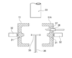
符号33はタンク本体の素材となる熱可塑性樹脂のパリソンで、押出成型機から所定温度に加熱されて押出される。35は前記タンク本体(図示せず)に内蔵される樹脂製長方形状のバッフルプレートで、このバッフルプレート35はブローピン機能を有しない(即ち円筒形状ではない)支持棒36の先端に水平状態で支持され、その両端部がそれぞれ両金型11、11Aの押圧部31に対向するように配在されている。
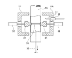
図12における符号37は一方の金型11、11Aに貫通状態で配在されたブローピンで、このブローピン37はシリンダの吹込手段38によりエアを吹込むタイプのものであり、その直径はタンク本体(図示せず)の上面に形成するエアブリーザ用の穴(図示せず)と同一外径のものである。
そこで、図12に示すように、前記パリソン33を解放状態にある金型11、11A間にドローダウンしてバッフルプレート35に被嵌した後、先ず駆動手段32により押圧部31を前進させてパリソン33の対向側壁を押圧し、前記バッフルプレート35の端部をパリソン33の内面に溶着固定する。この際押圧部31の押圧力は前記駆動手段32により任意に調整することができる。そして、前記溶着が完了後に支持棒36を金型11、11Aより抜き去る。
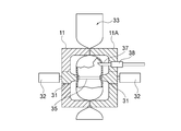
ついで、図13に示すように、両金型11、11Aを型締めしてパリソン33の上下端を密封するが、この際ブローピン37の先端部はパリソン33の側壁を貫通して内部に突入する。そして、パリソン33の内部にブローピン37の先端から圧縮エアを吹込んで金型11、11Aの内面に密着するよう膨張させ、中空体を成型することができる。
前述のように金型の型締めを行う場合には、一般に、中空成形機の型締機としては、電動式型締機と油圧式型締機がある。
中空成形機の電動式型締機において、型駆動のメインモータでの型開閉位置の制御と、金型内やその他部位のサブモータのサーボモータの動作を制御することで、型開閉動作と金型内やその他部位のサーボモータ動作を同期させることができる機構を特徴とする開閉位置検出機構及び同期装置がある。
前述の特許文献1の構成のような型の加圧力をコントロールすることで、膜厚を均一にするものはあったが、位置の同期をさせるものはなかった。
中空成形機の電動式型締機において、型駆動のメインモータでの型開閉位置の制御と、金型内やその他部位のサブモータのサーボモータの動作を制御することで、型開閉動作と金型内やその他部位のサーボモータ動作を同期させることができる機構を特徴とする開閉位置検出機構及び同期装置がある。
前述の特許文献1の構成のような型の加圧力をコントロールすることで、膜厚を均一にするものはあったが、位置の同期をさせるものはなかった。
前述の従来の油圧式型締装置について述べると、図7及び図9は、各プラテン5~7が全て連動して可動する構成であり、図7は型開状態を示し、図8は型締状態を示している。
すなわち、図7において符号1で示されるものは、基台であり、前記基台1上には、レール等からなり互いに離間しかつ独立して第1、第2、第3直動ガイド2、3、4が設けられている。
すなわち、図7において符号1で示されるものは、基台であり、前記基台1上には、レール等からなり互いに離間しかつ独立して第1、第2、第3直動ガイド2、3、4が設けられている。
前記第1、第2、第3直動ガイド2、3、4上には、第1、第2、第3プラテン5、6、7が直動自在に設けられている。
前記第1、第3プラテン5、7間は、複数のタイバー8(実際には4本)によって締結され、各ナット9によって固定されている。
前記各タイバー8は、前記第2、第3プラテン6、7の貫通孔6a、7aを作動自在な状態で貫通しており、前記第2、第3プラテン6、7は互いに接離自在となるように構成されている。
前記第1、第3プラテン5、7間は、複数のタイバー8(実際には4本)によって締結され、各ナット9によって固定されている。
前記各タイバー8は、前記第2、第3プラテン6、7の貫通孔6a、7aを作動自在な状態で貫通しており、前記第2、第3プラテン6、7は互いに接離自在となるように構成されている。
前記第1プラテン5の内面5aには、油圧ユニット10によって突出子12Aが出入り自在に構成された油圧シリンダ12が設けられている。
前記第2、第3プラテン6、7の内面6A、7Aには、第1金型11及び第2金型11Aが設けられており、前記第2、第3プラテン6、7の下部には、L字型をなす第1、第2レバー13、14とギア15の組合せによる周知のラック・アンド・ピニオンによる連動機構15Aが設けられている。
前記基台1には、前記第2プラテン6の直動を検出するための周知のリニアスケール又はポテンショメータからなるアナログ型直動検出器16が設けられている。
尚、前述の各金型11、11Aの構造は、図示していないが、例えば、図11~図12の従来例に示されるように構成されている。
前記第2、第3プラテン6、7の内面6A、7Aには、第1金型11及び第2金型11Aが設けられており、前記第2、第3プラテン6、7の下部には、L字型をなす第1、第2レバー13、14とギア15の組合せによる周知のラック・アンド・ピニオンによる連動機構15Aが設けられている。
前記基台1には、前記第2プラテン6の直動を検出するための周知のリニアスケール又はポテンショメータからなるアナログ型直動検出器16が設けられている。
尚、前述の各金型11、11Aの構造は、図示していないが、例えば、図11~図12の従来例に示されるように構成されている。
前述の構成において、図7の型開状態で、油圧ユニット10を介して油圧シリンダ12を作動させると、突出子12Aが第2プラテン6を、図上で右側へ押すと、連動機構15Aを介して第3可動プラテン7が第2プラテン6側へ引き寄せられ、各金型11、11Aは互いに圧接することにより、型締めが達成される。
前述における第2プラテン6の直動状態は、前記アナログ型直動検出器16によってアナログ値として検出される。
前述における第2プラテン6の直動状態は、前記アナログ型直動検出器16によってアナログ値として検出される。
従来の型締装置及び方法は、以上のように構成されていたため、次のような課題が存在していた。
例えば、図9で示される従来の電動式型締装置においては、制御盤20によってサーボモータ21、エンコーダ22、ボールネジ23を介してプラテン5、6(図7に示す)の開閉を制御し、前記エンコーダ22からの回転検出信号22aに基づいてプラテン位置情報20aを例えば金型11、11A(図7)内のサーボモータ24と同期させることはできるが、型締動作自体が電動であるため、サーボモータ同志の同期は可能であるが、小型モータが多くて型締力が足りないため、模様等の多い大形の成形品の成形には好適ではなかった。
例えば、図9で示される従来の電動式型締装置においては、制御盤20によってサーボモータ21、エンコーダ22、ボールネジ23を介してプラテン5、6(図7に示す)の開閉を制御し、前記エンコーダ22からの回転検出信号22aに基づいてプラテン位置情報20aを例えば金型11、11A(図7)内のサーボモータ24と同期させることはできるが、型締動作自体が電動であるため、サーボモータ同志の同期は可能であるが、小型モータが多くて型締力が足りないため、模様等の多い大形の成形品の成形には好適ではなかった。
また、図10で示される従来の油圧式型締装置においては、ここでは、図9と同一部分には同一符号を付して説明している。
すなわち、油圧ユニット10からの油10aを油圧シリンダ12に供給し、前記プラテン5、6の開閉を行うように構成され、リニアスケール又はポテンショメータ16(図7)で型開閉位置検出25を行い、型開閉位置信号15Aaが制御盤20に入力される。
前記制御盤20から出力されたプラテン位置情報20aは金型11、11A内のサーボモータ24に入力され、同期駆動することが望まれる。
すなわち、油圧ユニット10からの油10aを油圧シリンダ12に供給し、前記プラテン5、6の開閉を行うように構成され、リニアスケール又はポテンショメータ16(図7)で型開閉位置検出25を行い、型開閉位置信号15Aaが制御盤20に入力される。
前記制御盤20から出力されたプラテン位置情報20aは金型11、11A内のサーボモータ24に入力され、同期駆動することが望まれる。
しかしながら、油圧式型締装置における油圧式の型開閉動作は、リニアスケール又はポテンショメータを使用し、第2プラテンの位置の検出を行い、油圧シリンダを用いて型開閉制御を行っている。従来、リニアスケール又はポテンショメータで計測したプラテンの位置情報を用いて速度に変換して、型開閉の際の金型内のサーボモータの位置と速度を同期させようとした場合、リニアスケール又はポテンショメータとサーボモータの位置情報検出速度の差から、図10のアナログ型式の型開閉位置信号25aとプラテン位置情報20aとでは、通信速度に差があり、互いに同期することはできず、リニアスケール又はポテンショメータと金型内のサーボモータと型開閉動作の同期にズレが生じていた。
このように、同期にズレが生じるため、中空成形機の油圧式型締装置において、型開閉位置の制御と、金型内やその他部位のサーボモータ動作を制御することで、型開閉と金型内やその他部位のサーボモータ動作を高精度に同期させることができる開閉位置検出機構及び同期装置はなかった。そのため、従来の構成において大型で複雑な凹凸等を有する成形品の仕上げ精度を向上させることは極めて困難であった。
このように、同期にズレが生じるため、中空成形機の油圧式型締装置において、型開閉位置の制御と、金型内やその他部位のサーボモータ動作を制御することで、型開閉と金型内やその他部位のサーボモータ動作を高精度に同期させることができる開閉位置検出機構及び同期装置はなかった。そのため、従来の構成において大型で複雑な凹凸等を有する成形品の仕上げ精度を向上させることは極めて困難であった。
また、電動式の開閉動作は、サーボモータを使用しているので、開閉動作は高精度に制御することはできるが、油圧シリンダを使用した油圧式型締機に比べて型締力が劣っており、大型の成形品を高精度に成形することができなかった。
そのため、油圧式型締機よりも型締力の劣る電動式型締装置を伴う中空成形機では、シップイン成形などの繊細な動きを必要とする成形をすることができたが、電動式型締装置よりも型締力の勝る油圧式型締装置を伴う中空成形機においては、金型の細かい動きを高精度に制御することができないため、シップイン成形などの繊細な動きを必要とする成形をすることが困難であった。
そのため、油圧式型締機よりも型締力の劣る電動式型締装置を伴う中空成形機では、シップイン成形などの繊細な動きを必要とする成形をすることができたが、電動式型締装置よりも型締力の勝る油圧式型締装置を伴う中空成形機においては、金型の細かい動きを高精度に制御することができないため、シップイン成形などの繊細な動きを必要とする成形をすることが困難であった。
本発明は、上記のような従来技術の課題を解消するためになされたもので、特に、油圧式型締機構には、型開閉動作用のリニアスケール又はポテンショメータの代わりにデジタル型開閉位置検出手段のデジタル型開閉位置信号を使用し位置検出及びその位置情報を基に金型内やその他のサーボモータを動作させることで、型開閉と金型内やその他のサーボモータとの同期動作を可能とさせる型締装置及び方法を提供することを目的としている。
本発明による型締装置は、基台上にタイバーを介して設けられた第1、第2、第3プラテンのうちの少なくとも前記第2プラテンをアクチュエータで移動させ、前記第2、第3プラテンに設けられた第1、第2金型の型締及び型開を行うようにした型締装置において、少なくとも、前記各金型の一方、又は両方に設けられた金型用サーボモータと、前記基台上に設けられ前記第2プラテンの型位置を検出し、デジタル型開閉位置検出手段と、を有し、
前記デジタル型開閉位置検出手段からのデジタル型開閉位置信号と同期させて前記第1、第2金型用サーボモータの一方又は両方を同期駆動するようにした構成であり、また前記第1、第3プラテンは、前記第2プラテンに連動して移動する構成であり、また、請求項1、2、3の何れか1項に記載の型締装置は、中空成形機に組み合わせられる構成であり、また、前記デジタル型開閉位置検出手段は、回転検出器付きサーボモータとボールネジとからなる構成である。
前記デジタル型開閉位置検出手段は、エンコーダ、ゾルバ、磁気エンコーダの何れかとラック・アンド・ピニオンの組み合わせからなる構成であり、また、本発明による型締方法は、基台上にタイバーを介して設けられた第1、第2、第3プラテンのうちの少なくとも前記第2プラテンに設けられた第1、第2金型の型締及び型開を行うようにした型締方法において、少なくとも、前記各金型の一方、又は両方に設けられた金型用サーボ―モータと、
前記基台上に設けられ前記第2プラテンの型位置を検出し、デジタル型開閉位置検出手段と、を用い、前記デジタル型開閉位置検出手段からのデジタル型開閉位置信号と同期させて前記第1、第2金型用サーボ―モータの一方又は両方を同期駆動する方法であり、また、
前記第1、第3プラテンは、前記第2プラテンに連動して移動する方法であり、また、
請求項6、7、8の何れか1項に記載の型締方法は、中空成形機に組合せられる方法であり、また、前記デジタル型開閉位置検出手段は、回転検出器付サーボ―モータとボールネジとからなる方法である。
前記デジタル型開閉位置検出手段は、エンコーダ、レゾルバ、磁気エンコーダの何れかとラック・アンド・ピニオンの組合わせからなる方法である。
前記デジタル型開閉位置検出手段からのデジタル型開閉位置信号と同期させて前記第1、第2金型用サーボモータの一方又は両方を同期駆動するようにした構成であり、また前記第1、第3プラテンは、前記第2プラテンに連動して移動する構成であり、また、請求項1、2、3の何れか1項に記載の型締装置は、中空成形機に組み合わせられる構成であり、また、前記デジタル型開閉位置検出手段は、回転検出器付きサーボモータとボールネジとからなる構成である。
前記デジタル型開閉位置検出手段は、エンコーダ、ゾルバ、磁気エンコーダの何れかとラック・アンド・ピニオンの組み合わせからなる構成であり、また、本発明による型締方法は、基台上にタイバーを介して設けられた第1、第2、第3プラテンのうちの少なくとも前記第2プラテンに設けられた第1、第2金型の型締及び型開を行うようにした型締方法において、少なくとも、前記各金型の一方、又は両方に設けられた金型用サーボ―モータと、
前記基台上に設けられ前記第2プラテンの型位置を検出し、デジタル型開閉位置検出手段と、を用い、前記デジタル型開閉位置検出手段からのデジタル型開閉位置信号と同期させて前記第1、第2金型用サーボ―モータの一方又は両方を同期駆動する方法であり、また、
前記第1、第3プラテンは、前記第2プラテンに連動して移動する方法であり、また、
請求項6、7、8の何れか1項に記載の型締方法は、中空成形機に組合せられる方法であり、また、前記デジタル型開閉位置検出手段は、回転検出器付サーボ―モータとボールネジとからなる方法である。
前記デジタル型開閉位置検出手段は、エンコーダ、レゾルバ、磁気エンコーダの何れかとラック・アンド・ピニオンの組合わせからなる方法である。
本発明による型締装置及び方法は、以上のように構成されているため、次のような効果を得ることができる。
すなわち、基台上にタイバーを介して設けられた第1、第2、第3プラテンのうちの少なくとも前記第2プラテンをアクチュエータで移動させ、前記第2、第3プラテンに設けられた第1、第2金型の型締及び型開を行うようにした型締装置において、少なくとも、前記各金型の一方、又は両方に設けられた金型用サーボモータと、
前記基台上に設けられ前記第2プラテンの型位置を検出し、デジタル型開閉位置検出手段と、
前記デジタル型開閉位置検出手段と、を有し、
前記デジタル型開閉位置検出手段からのデジタル型開閉位置信号と同期させて前記第1、第2金型用サーボモータの一方又は、両方を同期駆動するようにしたことにより、従来はサーボモータを動力に使用した中空成形機の電動式型締機では型締めのパワーが足りずに成形できなかった大型な成形品を高精度に成形すること及び、中空成形機の油圧式型締機では同期ができないためにできなかった複雑で繊細な動きにも対応することができるという、油圧式と電動式の利点を兼ね備えたことで、大形かつ複雑で繊細な成形品を得ることができる。
また、新規の中空成形機の型締機を組み立てる場合にこの発明を用いるのみならず、この発明を既に納めている既存の油圧式型締機への追加改造として利用することができる為、既存の油圧式型締機を電動式型締機に買い替えるよりも後からの投資コストを安く抑えることができる。
また、前記第1、第3プラテンは、前記第2プラテンに連動して移動する構成からなることにより、多様な型締装置に適用できる。
前記デジタル型開閉位置検出手段は、回転検出器付サーボモータとボールネジとからなることにより、極めて簡単な構成によるデジタル型開閉位置検出手段を得ることができる。
また、前記デジタル型開閉位置検出手段は、エンコーダ、レゾルバ、磁気エンコーダの何れかとラック・アンド・ピニオンの組合わせかたなることにより、必要とするデジタル型開閉位置信号を容易に得ることができる。
すなわち、基台上にタイバーを介して設けられた第1、第2、第3プラテンのうちの少なくとも前記第2プラテンをアクチュエータで移動させ、前記第2、第3プラテンに設けられた第1、第2金型の型締及び型開を行うようにした型締装置において、少なくとも、前記各金型の一方、又は両方に設けられた金型用サーボモータと、
前記基台上に設けられ前記第2プラテンの型位置を検出し、デジタル型開閉位置検出手段と、
前記デジタル型開閉位置検出手段と、を有し、
前記デジタル型開閉位置検出手段からのデジタル型開閉位置信号と同期させて前記第1、第2金型用サーボモータの一方又は、両方を同期駆動するようにしたことにより、従来はサーボモータを動力に使用した中空成形機の電動式型締機では型締めのパワーが足りずに成形できなかった大型な成形品を高精度に成形すること及び、中空成形機の油圧式型締機では同期ができないためにできなかった複雑で繊細な動きにも対応することができるという、油圧式と電動式の利点を兼ね備えたことで、大形かつ複雑で繊細な成形品を得ることができる。
また、新規の中空成形機の型締機を組み立てる場合にこの発明を用いるのみならず、この発明を既に納めている既存の油圧式型締機への追加改造として利用することができる為、既存の油圧式型締機を電動式型締機に買い替えるよりも後からの投資コストを安く抑えることができる。
また、前記第1、第3プラテンは、前記第2プラテンに連動して移動する構成からなることにより、多様な型締装置に適用できる。
前記デジタル型開閉位置検出手段は、回転検出器付サーボモータとボールネジとからなることにより、極めて簡単な構成によるデジタル型開閉位置検出手段を得ることができる。
また、前記デジタル型開閉位置検出手段は、エンコーダ、レゾルバ、磁気エンコーダの何れかとラック・アンド・ピニオンの組合わせかたなることにより、必要とするデジタル型開閉位置信号を容易に得ることができる。
本発明による型締装置及び方法は、型締時にデジタル型開閉位置検出手段からのデジタル型開閉位置信号を用いることにより、金型等に設けられたサーボモータを前記デジタル型開閉位置信号と同期して作動できるようにすることである。
以下、図面と共に本発明による型締装置及び方法の好適な実施の形態について説明する。
尚、従来例と同一又は同等部分には、同一符号を付して説明すると共に、従来例である図7から図13と同一部分には同一符号を付し、その説明は重複を避けるために省略してこれを援用し、異なる部分についてのみ説明する。
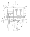
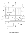
本発明による図1及び図2の型締装置において、前述の従来構成(図7及び図8)と異なる構成について説明する。尚、図1及び図2の構成は、図7及び図8と同様に各プラテン5、6、7が可動型である。
図1における基台1上には、エンコーダ等の回転検出器40とサーボモータ41を一体化してなる回転検出器付サーボモータ42が設けられ、この回転検出器付サーボモータ42に設けられたボールネジ43の先端43aは第2可動プラテン6に当接している。
前記ボールネジ43の先端43aには、軸受(図示せず)が設けられ、先端43aは第2可動プラテン6に対して当接しつつ回転できるように構成されている。
前述の回転検出器付サーボモータ42とボールネジ43によってデジタル型開閉位置検出手段100を構成し、前記デジタル型開閉位置検出手段100からは、図3で示されるように、デジタル型開閉位置検出信号100aが出力されるように構成されている。
尚、従来例と同一又は同等部分には、同一符号を付して説明すると共に、従来例である図7から図13と同一部分には同一符号を付し、その説明は重複を避けるために省略してこれを援用し、異なる部分についてのみ説明する。
本発明による図1及び図2の型締装置において、前述の従来構成(図7及び図8)と異なる構成について説明する。尚、図1及び図2の構成は、図7及び図8と同様に各プラテン5、6、7が可動型である。
図1における基台1上には、エンコーダ等の回転検出器40とサーボモータ41を一体化してなる回転検出器付サーボモータ42が設けられ、この回転検出器付サーボモータ42に設けられたボールネジ43の先端43aは第2可動プラテン6に当接している。
前記ボールネジ43の先端43aには、軸受(図示せず)が設けられ、先端43aは第2可動プラテン6に対して当接しつつ回転できるように構成されている。
前述の回転検出器付サーボモータ42とボールネジ43によってデジタル型開閉位置検出手段100を構成し、前記デジタル型開閉位置検出手段100からは、図3で示されるように、デジタル型開閉位置検出信号100aが出力されるように構成されている。
前記回転器付サーボモータ42の回転検出器40は、通常エンコーダのパルス状の矩形波を波形整形後にカウンタでカウントしたカウント値を前記デジタル型開閉位置検出信号100aとして用いているため、従来のリニアスケール又はポテンショメータの出力信号よりも通信速度が速い。
また、前記デジタル型開閉位置検出手段100は、前述のボールネジ43との組合せに限ることなく、ボールネジ43を図示しないロッド状のラックに代え、このラックに設けられたピニオン(すなわち、周知のラック・アンド・ピニオン)にエンコーダ、レゾルバ、磁気エンコーダの何れかを接続して前述のボールネジ43を用いた構成と同様の作用効果を得ることができる。
また、前記デジタル型開閉位置検出手段100は、前述のボールネジ43との組合せに限ることなく、ボールネジ43を図示しないロッド状のラックに代え、このラックに設けられたピニオン(すなわち、周知のラック・アンド・ピニオン)にエンコーダ、レゾルバ、磁気エンコーダの何れかを接続して前述のボールネジ43を用いた構成と同様の作用効果を得ることができる。
すなわち、前述のレゾルバは、回転検出器として極めて安定し、悪条件下でも二相の出力を得ることができ、A/D変換器によって通信速度の速い前記デジタル型開閉位置検出信号100aを得ることができる構成で、例えば、ハイブリッド自動車の回転検出に全て用いられている。
また、磁気エンコーダも、パルス状の矩形波を用いてカウント値として出力でき、例えば、新幹線の速度検出には全て用いられている。
また、磁気エンコーダも、パルス状の矩形波を用いてカウント値として出力でき、例えば、新幹線の速度検出には全て用いられている。
前述の第1、第2金型11、11Aの内部には、第1、第2可動子44、44Aを有する第1、第2金型用サーボモータ45,46が設けられ、従来構成の図11から図13で説明した各可動子31のように、成形時にパリソン33の形状に凹凸や模様等を形成するために用いられるように構成されている。
図1の構成は、アクチュエータ12の突出子11を突出させて各金型11、11Aの型締途中の状態を示しているが、この状態では、前記各可動子44、44Aが各金型11、11Aから突出していないため、各金型11、11Aで挟持したパリソン(図示せず)は、各金型11、11Aのキャビティの形状で成形される。
図1の構成は、アクチュエータ12の突出子11を突出させて各金型11、11Aの型締途中の状態を示しているが、この状態では、前記各可動子44、44Aが各金型11、11Aから突出していないため、各金型11、11Aで挟持したパリソン(図示せず)は、各金型11、11Aのキャビティの形状で成形される。
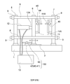
また、図2で示される構成においては、各金型用サーボモータ45、46を作動させて各可動子44、44Aを突出させ、これからパリソン(図示せず)の両側を、前述の図12のように押圧して、成形品(図示せず)の形状に凹部を形成させることができる。
従って、前述の図1及び図2の構成のように、油圧ユニット10によってアクチュエータ12の動作を制御する状態は、図3及び図4に示されている。
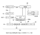
すなわち、図3の制御構成は、従来の油圧式型締装置を改造し、従来のアナログ型直動検出器16を用いた状態で、かつ、本発明によるボールネジ43、回転検出器40を有する回転検出器付サーボモータ42からなるデジタル型開閉位置検出手段100を追加し、前記回転検出器付サーボモータ42からのデジタル型開閉位置信号100aが前記制御盤20に入力されている。
従って、前述の図1及び図2の構成のように、油圧ユニット10によってアクチュエータ12の動作を制御する状態は、図3及び図4に示されている。
すなわち、図3の制御構成は、従来の油圧式型締装置を改造し、従来のアナログ型直動検出器16を用いた状態で、かつ、本発明によるボールネジ43、回転検出器40を有する回転検出器付サーボモータ42からなるデジタル型開閉位置検出手段100を追加し、前記回転検出器付サーボモータ42からのデジタル型開閉位置信号100aが前記制御盤20に入力されている。
図3の構成の場合、各プラテン5、6、7の開閉に連動して前記ボールネジ43を介して前記回転検出器付サーボモータ42からのデジタル型開閉位置検出信号100aを得ることができ、この内容に同期して各金型用サーボモータ45、46の動作を制御することができる。
すなわち、サーボモータ42のエンコーダ40は油圧式型締機構の型開閉に高速な位置検出器として作用して、型開閉の際にサーボモータ42のエンコーダ40で計測したプラテン6の位置情報を用いて速度に変換して、型開閉の際の金型11、11A内のサーボモータ45、46の位置と速度を同期させ金型内及びその他のサーボモータ45、46を制御盤20内のPLC(Programmable Logic Controller)によって同期動作をさせることができる。
尚、図3の構成においては、既存の油圧式型締装置を改造したものであるため、内蔵のアナログ型直動検出器16の型開閉位置検出信号25は、通信速度が遅いため用いられることはない。
すなわち、サーボモータ42のエンコーダ40は油圧式型締機構の型開閉に高速な位置検出器として作用して、型開閉の際にサーボモータ42のエンコーダ40で計測したプラテン6の位置情報を用いて速度に変換して、型開閉の際の金型11、11A内のサーボモータ45、46の位置と速度を同期させ金型内及びその他のサーボモータ45、46を制御盤20内のPLC(Programmable Logic Controller)によって同期動作をさせることができる。
尚、図3の構成においては、既存の油圧式型締装置を改造したものであるため、内蔵のアナログ型直動検出器16の型開閉位置検出信号25は、通信速度が遅いため用いられることはない。
図4の構成は、図3の改造型とは異なり、全く新しい新型として、前記アナログ型直動検出器16を用いることなく、本発明によるボールネジ43と回転検出器40付サーボモータ42からなるデジタル型開閉位置検出手段100のみを第2プラテン6の位置検出に用い、第2プラテン6と各金型用サーボモータ45,46を同期制御できる構成である。
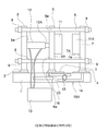
次に、図5及びず6は、図1及び図2で示した本発明による型締装置の他の形態を示すもので、図1及び図2の構成のように、全てのプラテン5、6、7が左右に移動する構成ではなく、第1、第3プラテン5、7は基台上に固定され、第2プラテン6のみが左右、すなわち、前記アクチュエータ12の突出子12Aによって前後に摺動するようにした型締装置にも適用することができる。
尚、図5及び図6の構成においては、前述の図1及び図2の構成と同一部分には同一符号を付して説明を省略し、異なる部分についてのみ説明した。
また、図1及び図2の構成と、図5及び図6の構成とは、構成が若干異なるが、その作用効果は同一である。
また、前述の状態では、油圧式として開示しているが、油圧式に相当するトルクの大型モータを採用すれば、電動式にも適用できるものである。
尚、図5及び図6の構成においては、前述の図1及び図2の構成と同一部分には同一符号を付して説明を省略し、異なる部分についてのみ説明した。
また、図1及び図2の構成と、図5及び図6の構成とは、構成が若干異なるが、その作用効果は同一である。
また、前述の状態では、油圧式として開示しているが、油圧式に相当するトルクの大型モータを採用すれば、電動式にも適用できるものである。
次に、前述の本発明による型締装置及び方法の要旨とするところは、以下の通りである。
すなわち、基台の上にタイバー8を介して、設けられた第1、第2、第3プラテンのうちの少なくとも前記第2プラテン5、6、7に設けられた第1、第2金型11、11Aの型締及び型開を行うようにした型締装置において、少なくとも前記各金型の一方、又は両方に設けられた金型サーボモータと、
前記基台上に設けられ前記第2プラテン6の型位置を検出するデジタル型開閉位置検出手段100と、を有し、
前記デジタル型開閉位置検出手段100からのデジタル開閉位置信号100aと同期させて前記第1、第2金型用サーボモータの一方又は両方を同期駆動するようにした構成であり、また、第1、第3プラテン5、7は前記第2プラテン6
に連動して移動する構成であり、また、
前記デジタル型開閉位置検出手段100は、エンコーダ、レゾルバ、磁気エンコーダの何れかとラック・アンド・ピニオンの組合わせからなる構成であり、また、請求項1、2、3の何れか1項に記載の型締装置は、中空成形機に組合わせられる構成であり、また、
前記デジタル型開閉位置検出手段100は、回転検出器付サーボモータ42とボールネジ43とからなる構成である。
また、本発明による型締方法は、基台上にタイバー8を介して設けられた第1、第2、第3プラテンのうちの少なくとも前記第2プラテン6をアクチュエータ12で移動させ、前記第2、第3プラテン5、7に設けられた第1、第2金型11、11Aの型締及び型開を行うようにした型締方法において、少なくとも、前記各金型の一方、又は両方に設けられた金型用サーボモータと、
前記基台上に設けられ前記第2プラテン6の型位置を検出するデジタル型開閉位置検出手段100と、を用い、
前記デジタル型開閉検出手段100からの型開閉位置信号100aと同期させて前記第1、第2金型用サーボモータの一方又は両方を同期駆動することを特徴とする型締方法。
前記第1、第3プラテン5、7は、前記プラテン6に連動して移動する方法であり、また、請求項7、8、9の何れか1項に記載の型締方法は、中空成形機に組合わせられる方法であり、また、
前記デジタル型開閉位置検出手段100は、回転検出器付サーボモータ42とボールネジ43とからなる方法である。
すなわち、基台の上にタイバー8を介して、設けられた第1、第2、第3プラテンのうちの少なくとも前記第2プラテン5、6、7に設けられた第1、第2金型11、11Aの型締及び型開を行うようにした型締装置において、少なくとも前記各金型の一方、又は両方に設けられた金型サーボモータと、
前記基台上に設けられ前記第2プラテン6の型位置を検出するデジタル型開閉位置検出手段100と、を有し、
前記デジタル型開閉位置検出手段100からのデジタル開閉位置信号100aと同期させて前記第1、第2金型用サーボモータの一方又は両方を同期駆動するようにした構成であり、また、第1、第3プラテン5、7は前記第2プラテン6
に連動して移動する構成であり、また、
前記デジタル型開閉位置検出手段100は、エンコーダ、レゾルバ、磁気エンコーダの何れかとラック・アンド・ピニオンの組合わせからなる構成であり、また、請求項1、2、3の何れか1項に記載の型締装置は、中空成形機に組合わせられる構成であり、また、
前記デジタル型開閉位置検出手段100は、回転検出器付サーボモータ42とボールネジ43とからなる構成である。
また、本発明による型締方法は、基台上にタイバー8を介して設けられた第1、第2、第3プラテンのうちの少なくとも前記第2プラテン6をアクチュエータ12で移動させ、前記第2、第3プラテン5、7に設けられた第1、第2金型11、11Aの型締及び型開を行うようにした型締方法において、少なくとも、前記各金型の一方、又は両方に設けられた金型用サーボモータと、
前記基台上に設けられ前記第2プラテン6の型位置を検出するデジタル型開閉位置検出手段100と、を用い、
前記デジタル型開閉検出手段100からの型開閉位置信号100aと同期させて前記第1、第2金型用サーボモータの一方又は両方を同期駆動することを特徴とする型締方法。
前記第1、第3プラテン5、7は、前記プラテン6に連動して移動する方法であり、また、請求項7、8、9の何れか1項に記載の型締方法は、中空成形機に組合わせられる方法であり、また、
前記デジタル型開閉位置検出手段100は、回転検出器付サーボモータ42とボールネジ43とからなる方法である。
本発明による型締装置及び方法は、型締め時のプラテンの位置をデジタル型開閉位置検出手段のデジタル型開閉位置検出信号を用いて各金型の各金型用サーボモータを同期駆動し、型開閉と各金型の動きを同期させることにより、大型で複雑な形状等の成形も容易にできる。
また、既存の型締装置に対して後付けすることもでき、新品と交換する費用よりも安く型締装置の性能向上を得ることができる。
また、既存の型締装置に対して後付けすることもでき、新品と交換する費用よりも安く型締装置の性能向上を得ることができる。
1 基台
2,3,4 第1、第2、第3直動用ガイド
5,6,7 第1、第2、第3プラテン
8 タイバー
9 ナット
10 油圧ユニット
11,11A 第1、第2金型
12 アクチュエータ(油圧シリンダ等)
13 第1レバー
14 第2レバー
15 ギア
15A 連動機構
16 アナログ型直動検出器
20 制御盤
40 回転検出器(エンコーダ等)
41 サーボモータ
42 回転検出器付サーボモータ
43 ボールネジ
44,44A 第1、第2可動子
45,46 第1、第2金型用サーボモータ
100 デジタル型開閉位置検出手段
100a デジタル型開閉位置検出信号
2,3,4 第1、第2、第3直動用ガイド
5,6,7 第1、第2、第3プラテン
8 タイバー
9 ナット
10 油圧ユニット
11,11A 第1、第2金型
12 アクチュエータ(油圧シリンダ等)
13 第1レバー
14 第2レバー
15 ギア
15A 連動機構
16 アナログ型直動検出器
20 制御盤
40 回転検出器(エンコーダ等)
41 サーボモータ
42 回転検出器付サーボモータ
43 ボールネジ
44,44A 第1、第2可動子
45,46 第1、第2金型用サーボモータ
100 デジタル型開閉位置検出手段
100a デジタル型開閉位置検出信号
Claims (10)
- 基台(1)上にタイバー(8)を介して設けられた第1、第2、第3プラテン(5,6,7)のうちの少なくとも前記第2プラテン(6)をアクチュエータ(12)で移動させ、前記第2、第3プラテン(6,7)に設けられた第1、第2金型(11,11A)の型締及び型開を行うようにした型締装置において、少なくとも、前記各金型(11,11A)の一方、又は両方に設けられた金型用サーボモータ(45,46)と、
前記基台(1)上に設けられ前記第2プラテン(6)の型位置を検出するデジタル型開閉位置検出手段(100)からを有し、
前記デジタル型開閉位置検出手段(100)のデジタル型開閉位置信号(100a)と同期させて前記第1、第2金型用サーボモータ(45,46)の一方又は両方を同期駆動するように構成したことを特徴とする型締装置。 - 前記第1、第3プラテン(5,7)は、前記第2プラテン(6)に連動して移動する構成からなることを特徴とする請求項1記載の型締装置。
- 前記デジタル型開閉位置検出手段(100)は、エンコーダ、レゾルバ、磁気エンコーダの何れかとラック・アンド・ピニオンの組合わせからなることを特徴とする請求項1または、2記載の型締装置。
- 請求項1、2、3の何れか1項に記載の型締装置は、中空成形機に組合わせられることを特徴とする型締装置。
- 前記デジタル型開閉位置検出手段(100)は、回転検出器付サーボモータ(42)とボールネジ(43)とからなることを特徴とする請求項1、2、4の何れか1項記載の型締装置。
- 基台(1)状にタイバー(8)を介して設けられた第1、第2、第3プラテン(5,6,7)のうちの少なくとも前記第2、第3プラテン(6)をアクチュエータ(12)で移動させ、前記第2、第3プラテン(6,7)に設けられた第1、第2金型(11,11A)の型締及び型開を行うようにした型締方法において、少なくとも、前記各金型(11,11A)の一方、又は両方に設けられた金型用サーボモータ(45,46)と、
前記基台(1)上に設けられ前記第2プラテン(6)の型位置を検出するデジタル型開閉位置検出手段(100)と、を用い、
前記デジタル型開閉位置検出手段(100)からのデジタル型開閉位置信号(100a)と同期させて前記第1、第2金型用サーボモータ(45,46)の一方又は両方を同期駆動することを特徴とする型締方法。 - 前記第1、第3プラテン(5,7)は、前記第2プラテン(6)に連動して移動することを特徴とする請求項1記載の型締方法。
- 前記デジタル型開閉位置検出手段(100)は、エンコーダ、レゾルバ、磁気エンコーダの何れかとラック・アンド・ピニオンの組合わせからなることを特徴とする請求項6又は7記載の型締方法。
- 請求項6、7、8の何れか1項に記載の型締方法は、中空成形機に組合わせられることを特徴とする型締方法。
- 前記デジタル型開閉位置検出手段(100)は、回転検出器付サーボモータ(42)とボールネジ(43)とからなることを特徴とする請求項6、7、9の何れか1項記載の型締方法。
Priority Applications (2)
| Application Number | Priority Date | Filing Date | Title |
|---|---|---|---|
| US16/070,906 US10688704B2 (en) | 2016-01-19 | 2016-12-26 | Mold clamping device and method |
| CN201680079395.6A CN108472857B (zh) | 2016-01-19 | 2016-12-26 | 合模装置及方法 |
Applications Claiming Priority (2)
| Application Number | Priority Date | Filing Date | Title |
|---|---|---|---|
| JP2016007808A JP6395188B2 (ja) | 2016-01-19 | 2016-01-19 | 型締装置及び方法 |
| JP2016-007808 | 2016-01-19 |
Publications (1)
| Publication Number | Publication Date |
|---|---|
| WO2017126298A1 true WO2017126298A1 (ja) | 2017-07-27 |
Family
ID=59361709
Family Applications (1)
| Application Number | Title | Priority Date | Filing Date |
|---|---|---|---|
| PCT/JP2016/088713 Ceased WO2017126298A1 (ja) | 2016-01-19 | 2016-12-26 | 型締装置及び方法 |
Country Status (4)
| Country | Link |
|---|---|
| US (1) | US10688704B2 (ja) |
| JP (1) | JP6395188B2 (ja) |
| CN (1) | CN108472857B (ja) |
| WO (1) | WO2017126298A1 (ja) |
Families Citing this family (5)
| Publication number | Priority date | Publication date | Assignee | Title |
|---|---|---|---|---|
| TWI865481B (zh) * | 2019-01-30 | 2024-12-11 | 日商京洛股份有限公司 | 成型裝置、以及成型品的製造系統 |
| JP7248973B2 (ja) * | 2019-01-30 | 2023-03-30 | キョーラク株式会社 | 成形装置 |
| JP7317308B2 (ja) * | 2019-01-30 | 2023-07-31 | キョーラク株式会社 | 成形装置 |
| LU102744B1 (fr) * | 2021-04-06 | 2022-10-06 | Plastic Omnium Advanced Innovation & Res | Ensemble de moule pour la fabrication d'un réservoir de véhicule automobile |
| WO2025079704A1 (ja) * | 2023-10-13 | 2025-04-17 | 日精エー・エス・ビー機械株式会社 | 樹脂製容器のブロー成形装置 |
Citations (5)
| Publication number | Priority date | Publication date | Assignee | Title |
|---|---|---|---|---|
| JPH04323020A (ja) * | 1990-10-15 | 1992-11-12 | Krupp Kautex Mas Bau Gmbh | 熱可塑性材料の中空体の製造方法および装置 |
| JPH0671737A (ja) * | 1992-08-28 | 1994-03-15 | Japan Steel Works Ltd:The | 中空成形機の金型移動制御装置 |
| JP2004255386A (ja) * | 2003-02-24 | 2004-09-16 | Toyota Motor Corp | 成形機および成形方法 |
| JP2006256178A (ja) * | 2005-03-18 | 2006-09-28 | Ube Machinery Corporation Ltd | 射出成形機における型締装置の制御方法 |
| JP2008284748A (ja) * | 2007-05-16 | 2008-11-27 | Sumitomo Heavy Ind Ltd | 型締制御装置 |
Family Cites Families (6)
| Publication number | Priority date | Publication date | Assignee | Title |
|---|---|---|---|---|
| JPH0661808B2 (ja) * | 1986-09-22 | 1994-08-17 | フアナツク株式会社 | 電動式直圧型締機構における金型タッチ位置検出方法 |
| JP2000334820A (ja) * | 1999-05-25 | 2000-12-05 | Japan Steel Works Ltd:The | 中空成形機の金型駆動方法及びその装置 |
| JP5175477B2 (ja) * | 2007-03-12 | 2013-04-03 | みのる化成株式会社 | ブロー成形機の型締め装置 |
| CN101888921B (zh) * | 2008-03-25 | 2013-06-19 | 三菱重工塑胶科技股份有限公司 | 双材料成型用注塑成型机及其控制方法 |
| JP5324377B2 (ja) * | 2009-09-30 | 2013-10-23 | 三菱重工プラスチックテクノロジー株式会社 | 射出発泡成形機 |
| CN102529065A (zh) * | 2012-03-05 | 2012-07-04 | 邓永斌 | 带直线轨道的单向旋转挤出吹瓶机 |
-
2016
- 2016-01-19 JP JP2016007808A patent/JP6395188B2/ja active Active
- 2016-12-26 CN CN201680079395.6A patent/CN108472857B/zh not_active Expired - Fee Related
- 2016-12-26 WO PCT/JP2016/088713 patent/WO2017126298A1/ja not_active Ceased
- 2016-12-26 US US16/070,906 patent/US10688704B2/en active Active
Patent Citations (5)
| Publication number | Priority date | Publication date | Assignee | Title |
|---|---|---|---|---|
| JPH04323020A (ja) * | 1990-10-15 | 1992-11-12 | Krupp Kautex Mas Bau Gmbh | 熱可塑性材料の中空体の製造方法および装置 |
| JPH0671737A (ja) * | 1992-08-28 | 1994-03-15 | Japan Steel Works Ltd:The | 中空成形機の金型移動制御装置 |
| JP2004255386A (ja) * | 2003-02-24 | 2004-09-16 | Toyota Motor Corp | 成形機および成形方法 |
| JP2006256178A (ja) * | 2005-03-18 | 2006-09-28 | Ube Machinery Corporation Ltd | 射出成形機における型締装置の制御方法 |
| JP2008284748A (ja) * | 2007-05-16 | 2008-11-27 | Sumitomo Heavy Ind Ltd | 型締制御装置 |
Also Published As
| Publication number | Publication date |
|---|---|
| US20190022910A1 (en) | 2019-01-24 |
| JP2017128007A (ja) | 2017-07-27 |
| US10688704B2 (en) | 2020-06-23 |
| CN108472857B (zh) | 2021-01-01 |
| CN108472857A (zh) | 2018-08-31 |
| JP6395188B2 (ja) | 2018-09-26 |
Similar Documents
| Publication | Publication Date | Title |
|---|---|---|
| JP6395188B2 (ja) | 型締装置及び方法 | |
| JP6420463B2 (ja) | 二軸延伸ブロー成形装置 | |
| JP5031867B2 (ja) | 射出成形方法、およびその装置 | |
| US7886806B2 (en) | Method for removing a casted part for use in a die casting machine | |
| JP2018171904A (ja) | 射出成形機 | |
| JP2007167922A (ja) | ダイカストマシンにおける離型剤のスプレイ方法及びその装置 | |
| JP5633983B2 (ja) | 複合成形品の射出成形機およびその作動方法 | |
| CN108688104B (zh) | 注塑成形机的控制方法和注塑成形机 | |
| KR101342889B1 (ko) | 복합 성형품용 사출성형기 및 그 성형방법 | |
| EP1914061B1 (en) | Machine for moulding plastic containers using means for moving mould-support unit comprising two in-line connecting tools | |
| JP5981289B2 (ja) | ブロー成形機の金型の型締め装置 | |
| JP2008110498A (ja) | 射出成形機の型締装置および射出成形機の成形方法 | |
| JP2011136439A (ja) | 複合成形品の射出成形機およびその作動方法 | |
| JP6525347B2 (ja) | 複合成形品用の射出成形機および複合成形品用の射出成形機の制御方法 | |
| TWI503219B (zh) | A thin plate injection molding method and a thin plate injection press forming apparatus | |
| CN101119837B (zh) | 用于具有多层模具的注塑机的合模装置 | |
| JP5489059B2 (ja) | 型締装置のハーフナット | |
| JP4947403B2 (ja) | ガラス製品成形機 | |
| JP2019111672A (ja) | 射出吹込成形機の型開閉方法 | |
| CN104070652A (zh) | 注射成型机 | |
| JP6537209B2 (ja) | 射出成形機の制御方法および射出成形機 | |
| JP4827946B2 (ja) | 多材質射出成形機および多材質射出成形機の制御方法 | |
| JP5127880B2 (ja) | 射出成形機およびその成形方法 | |
| JP6765767B2 (ja) | 射出吹込成形機の運転方法 | |
| JP2019077047A (ja) | 複合強化繊維樹脂成形品の成形方法 |
Legal Events
| Date | Code | Title | Description |
|---|---|---|---|
| 121 | Ep: the epo has been informed by wipo that ep was designated in this application |
Ref document number: 16886536 Country of ref document: EP Kind code of ref document: A1 |
|
| NENP | Non-entry into the national phase |
Ref country code: DE |
|
| 122 | Ep: pct application non-entry in european phase |
Ref document number: 16886536 Country of ref document: EP Kind code of ref document: A1 |