WO2017126293A1 - 燃料噴射装置 - Google Patents
燃料噴射装置 Download PDFInfo
- Publication number
- WO2017126293A1 WO2017126293A1 PCT/JP2016/088605 JP2016088605W WO2017126293A1 WO 2017126293 A1 WO2017126293 A1 WO 2017126293A1 JP 2016088605 W JP2016088605 W JP 2016088605W WO 2017126293 A1 WO2017126293 A1 WO 2017126293A1
- Authority
- WO
- WIPO (PCT)
- Prior art keywords
- nozzle
- hole
- injection
- fuel
- nozzle hole
- Prior art date
- Legal status (The legal status is an assumption and is not a legal conclusion. Google has not performed a legal analysis and makes no representation as to the accuracy of the status listed.)
- Ceased
Links
Images



Classifications
-
- F—MECHANICAL ENGINEERING; LIGHTING; HEATING; WEAPONS; BLASTING
- F02—COMBUSTION ENGINES; HOT-GAS OR COMBUSTION-PRODUCT ENGINE PLANTS
- F02M—SUPPLYING COMBUSTION ENGINES IN GENERAL WITH COMBUSTIBLE MIXTURES OR CONSTITUENTS THEREOF
- F02M61/00—Fuel-injectors not provided for in groups F02M39/00 - F02M57/00 or F02M67/00
- F02M61/16—Details not provided for in, or of interest apart from, the apparatus of groups F02M61/02 - F02M61/14
- F02M61/18—Injection nozzles, e.g. having valve seats; Details of valve member seated ends, not otherwise provided for
Definitions
- the present disclosure relates to a fuel injection device that injects fuel.
- Patent Document 1 describes a fuel injection device in which the inner walls of all the injection holes are cylindrical, that is, a straight shape.
- the injection angle which is the angle formed by the axis of the nozzle portion of the fuel injection device and the central axis of the injection hole, is set to be the same for all injection holes. Therefore, for example, when the fuel injection device is mounted on the side of the combustion chamber, the fuel is injected from the specific injection hole toward the ignition device, and the fuel is injected from the other injection holes toward the piston. Is difficult.
- the fuel injection device of Patent Document 1 all the hole diameters are formed to be different from each other. For this reason, the fuel spray injected from the injection hole having a small hole diameter has a large penetration force and may adhere to the inner wall of the ignition device or the combustion chamber. If fuel spray adheres to the inner wall of the combustion chamber, there is a risk of causing oil dilution. Further, the fuel spray injected from the nozzle hole having a large hole diameter has a small penetration force and is pushed back by the tumble flow in the combustion chamber, which may make it difficult to generate a homogeneous air-fuel mixture.
- the present disclosure has been made in view of the above-described problem, and an object of the present disclosure is to provide a fuel injection device capable of setting a fuel spray penetrating force to have different magnitudes depending on the fuel injection angle between a plurality of injection holes. Is to provide.
- the fuel injection device includes a nozzle portion.
- the nozzle part connects a nozzle cylinder part that forms a fuel passage inside, a nozzle bottom part that closes one end of the nozzle cylinder part, and a surface on the nozzle cylinder part side of the nozzle bottom part and a surface opposite to the nozzle cylinder part.
- a plurality of injection holes for injecting fuel in the fuel passage are provided.
- the nozzle hole includes at least one nozzle hole group including one first nozzle hole and one second nozzle hole.
- the first nozzle hole includes a first inlet opening formed on a surface of the nozzle bottom on the nozzle tube side, a first outlet opening formed on a surface of the nozzle bottom opposite to the nozzle tube, and a first A first jet formed in a taper shape so as to be connected to the first inlet opening and the first outlet opening and away from the first central axis as the central axis as it goes from the first inlet opening to the first outlet opening. It has a hole inner wall.
- the second nozzle hole has a second inlet opening formed on a surface of the nozzle bottom on the nozzle tube side, a second outlet opening formed on a surface of the nozzle bottom opposite to the nozzle tube, and a second A second jet formed in a tapered shape that connects the two inlet openings and the second outlet openings and leaves the second central axis, which is the central axis, from the second inlet opening side toward the second outlet opening side. It has a hole inner wall.
- the spray of fuel injected from the first nozzle hole or the second nozzle hole is transmitted from the first central axis or the second central axis. It spreads away. Thereby, atomization of fuel spray can be achieved while reducing the penetration force of fuel spray.
- ⁇ i1 (deg) is a first injection angle that is an angle formed by the axis of the nozzle cylinder and the first central axis, and a second injection angle that is an angle formed by the axis of the nozzle cylinder and the second central axis.
- the first taper angle which is the angle formed by the contour of the inner wall of the first nozzle hole in the cross section of the virtual plane including all the first central axis of the first nozzle hole, ⁇ t1 (deg)
- the second taper angle which is the angle formed by the contour of the inner wall of the second nozzle hole in the cross section of the virtual plane including the second central axis, is ⁇ t2 (deg)
- the first nozzle hole and the second nozzle hole have ⁇ i1 ⁇ i2 , ⁇ t1> ⁇ t2.
- the penetration force of the fuel spray injected from the first injection hole having a relatively small injection angle can be made smaller than the penetration force of the fuel spray injected from the second injection hole having a relatively large injection angle. .
- the penetration force of a fuel spray can be set to a different magnitude
- fuel injection device when the fuel injection device is mounted on the side of the combustion chamber of the internal combustion engine, fuel is injected from the first injection hole toward the ignition device side, and from the second injection hole toward the piston side. Fuel can be injected. Further, since the fuel spray injected toward the ignition device has a small penetration force, it can be prevented from adhering to the inner wall of the combustion chamber beyond the ignition device. Further, since the fuel spray injected toward the piston side has a large penetration force, a homogeneous air-fuel mixture can be generated without being pushed back by the tumble flow in the combustion chamber.
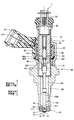
- FIG. 1 is a cross-sectional view illustrating a fuel injection device according to a first embodiment of the present disclosure.
- the figure which shows the state which applied the fuel-injection apparatus by 1st Embodiment of this indication to the internal combustion engine.
- Sectional drawing which shows the nozzle hole of the fuel-injection apparatus by 1st Embodiment of this indication, and its vicinity.
- FIG. 1 shows a fuel injection device according to the first embodiment of the present disclosure.
- the fuel injection device 1 is applied to, for example, a gasoline engine (hereinafter simply referred to as “engine”) 80 as an internal combustion engine, and injects gasoline as fuel and supplies it to the engine 80 (see FIG. 2).
- engine 80 a gasoline engine (hereinafter simply referred to as “engine”) 80 as an internal combustion engine, and injects gasoline as fuel and supplies it to the engine 80 (see FIG. 2).
- the engine 80 includes a cylindrical cylinder block 81, a piston 82, a cylinder head 90, an intake valve 95, an exhaust valve 96, and the like.
- the piston 82 is provided so as to be capable of reciprocating inside the cylinder block 81.
- the cylinder head 90 is provided to close the open end of the cylinder block 81.
- a combustion chamber 83 is formed between the inner wall of the cylinder block 81, the wall surface of the cylinder head 90, and the piston 82. The volume of the combustion chamber 83 increases or decreases as the piston 82 reciprocates.
- the cylinder head 90 has an intake manifold 91 and an exhaust manifold 93.
- An intake passage 92 is formed in the intake manifold 91.
- One end of the intake passage 92 is open to the atmosphere side, and the other end is connected to the combustion chamber 83.
- the intake passage 92 guides air sucked from the atmosphere side (hereinafter referred to as “intake”) to the combustion chamber 83.
- An exhaust passage 94 is formed in the exhaust manifold 93.
- the exhaust passage 94 has one end connected to the combustion chamber 83 and the other end opened to the atmosphere side.
- the exhaust passage 94 guides air containing combustion gas generated in the combustion chamber 83 (hereinafter referred to as “exhaust”) to the atmosphere side.
- the intake valve 95 is provided in the cylinder head 90 so as to be reciprocally movable by rotation of a cam of a driven shaft that rotates in conjunction with a drive shaft (not shown).
- the intake valve 95 can open and close between the combustion chamber 83 and the intake passage 92 by reciprocating.
- the exhaust valve 96 is provided in the cylinder head 90 so as to be reciprocally movable by rotation of the cam.
- the exhaust valve 96 can open and close between the combustion chamber 83 and the exhaust passage 94 by reciprocating.
- the fuel injection device 1 is mounted on the cylinder block 81 side of the intake passage 92 of the intake manifold 91.
- the fuel injection device 1 is provided such that the shaft is inclined with respect to the shaft of the combustion chamber 83 or is in a twisted relationship.
- the fuel injection device 1 is provided on the side of the combustion chamber 83. That is, the fuel injection device 1 is used by being mounted on the side of the engine 80.
- an ignition plug 97 as an ignition device is provided between the intake valve 95 and the exhaust valve 96 of the cylinder head 90, that is, at a position corresponding to the center of the combustion chamber 83.
- the spark plug 97 is provided at a position where the fuel injected from the fuel injection device 1 does not directly adhere and is capable of igniting combustible air mixed with the fuel.
- the engine 80 is a direct injection gasoline engine.
- the fuel injection device 1 is provided such that the plurality of injection holes 13 are exposed in a radially outer portion of the combustion chamber 83.
- the fuel injection device 1 is supplied with fuel pressurized to a fuel injection pressure by a fuel pump (not shown).
- a conical spray Fo is injected into the combustion chamber 83 from the plurality of injection holes 13 of the fuel injection device 1.
- the fuel injection device 1 includes a nozzle portion 10, a housing 20, a needle 30, a movable core 40, a fixed core 41, a spring 43 as a valve seat side biasing member, a coil 44, and the like.
- the nozzle portion 10 is formed of a metal such as martensitic stainless steel.
- the nozzle unit 10 is subjected to a quenching process so as to have a predetermined hardness.
- the nozzle portion 10 includes a nozzle cylinder portion 11, a nozzle bottom portion 12, an injection hole 13, and a valve seat 14.
- the nozzle cylinder portion 11 is formed in a cylindrical shape.
- the nozzle bottom 12 closes one end of the nozzle cylinder 11.
- the nozzle hole 13 is formed so as to connect the surface 121, that is, the inner wall, of the nozzle bottom portion 12 on the nozzle tube portion 11 side, and the surface 122, that is, the outer wall, on the opposite side of the nozzle tube portion 11 (see FIG. 3).
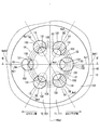
- a plurality of nozzle holes 13 are formed in the nozzle bottom 12. In the present embodiment, six nozzle holes 13 are formed (see FIG. 4).
- the valve seat 14 is formed in an annular shape around the nozzle hole 13 on the nozzle cylinder portion 11 side of the nozzle bottom portion 12. The nozzle hole 13 will be described in detail later.
- the housing 20 includes a nozzle holder 26, a first cylinder member 21, a second cylinder member 22, a third cylinder member 23, an inlet portion 24, a filter 25, and the like.
- the nozzle holder 26 is formed in a cylindrical shape from a magnetic material such as ferritic stainless steel. Inside the one end of the nozzle holder 26, an end portion of the nozzle cylinder portion 11 opposite to the nozzle bottom portion 12 is connected. The nozzle holder 26 and the nozzle part 10 are connected by welding, for example. Thereby, the nozzle holder 26 holds the nozzle unit 10.
- the first cylinder member 21, the second cylinder member 22, and the third cylinder member 23 are all formed in a substantially cylindrical shape.
- the 1st cylinder member 21, the 2nd cylinder member 22, and the 3rd cylinder member 23 are arrange
- the first cylinder member 21 and the third cylinder member 23 are made of a magnetic material such as ferritic stainless steel and subjected to a magnetic stabilization process.
- the first cylinder member 21 and the third cylinder member 23 have a relatively low hardness.
- the second cylindrical member 22 is formed of a nonmagnetic material such as austenitic stainless steel, for example.
- the hardness of the second cylinder member 22 is higher than the hardness of the first cylinder member 21 and the third cylinder member 23.
- the first cylinder member 21 is provided so that the outer wall at the end opposite to the second cylinder member 22 is fitted to the inner wall at the end opposite to the nozzle portion 10 of the nozzle holder 26.
- the inlet portion 24 is formed in a cylindrical shape from a magnetic material such as ferritic stainless steel.
- the inlet portion 24 is provided so that one end thereof is connected to the end portion of the third cylindrical member 23 opposite to the second cylindrical member 22.
- a fuel passage 100 is formed inside the housing 20.
- the fuel passage 100 is connected to the injection hole 13. That is, the nozzle cylinder part 11 forms the fuel passage 100 inside.
- a pipe (not shown) is connected to the inlet 24 on the side opposite to the third cylinder member 23. Thereby, the fuel from the fuel supply source (fuel pump) flows into the fuel passage 100 via the pipe.
- the fuel passage 100 guides fuel to the nozzle hole 13.
- the filter 25 is provided inside the inlet portion 24.
- the filter 25 collects foreign matters in the fuel flowing into the fuel passage 100.
- the needle 30 is formed in a rod shape from a metal such as martensitic stainless steel.
- the needle 30 is quenched so as to have a predetermined hardness.
- the hardness of the needle 30 is set substantially equal to the hardness of the nozzle portion 10.
- the needle 30 is accommodated in the housing 20 so as to be able to reciprocate in the fuel passage 100 in the axial direction of the housing 20.
- the needle 30 has a seat portion 31, a large diameter portion 32, and the like.
- the seat portion 31 is formed at an end portion of the needle 30 on the nozzle portion 10 side, and can contact the valve seat 14.
- the large diameter portion 32 is formed in the vicinity of the seat portion 31 at the end of the needle 30 on the valve seat 14 side.
- the large diameter portion 32 is set to have an outer diameter larger than the outer diameter of the end portion of the needle 30 on the valve seat 14 side.
- the large diameter portion 32 is formed so that the outer wall slides with the inner wall of the nozzle cylinder portion 11 of the nozzle portion 10. As a result, the needle 30 is guided to reciprocate in the axial direction at the end of the valve seat 14.
- the large-diameter portion 32 is formed with a notch 33 so that a plurality of portions in the circumferential direction of the outer wall are notched. Thereby, the fuel can flow between the notch 33 and the inner wall of the nozzle cylinder 11.
- the needle 30 opens and closes the injection hole 13 when the seat portion 31 is separated (separated) from the valve seat 14 or abuts (sits) the valve seat 14.
- the direction in which the needle 30 is separated from the valve seat 14 is referred to as the valve opening direction
- the direction in which the needle 30 contacts the valve seat 14 is referred to as the valve closing direction.
- the movable core 40 is formed in a cylindrical shape from a magnetic material such as ferritic stainless steel.
- the movable core 40 is subjected to a magnetic stabilization process.
- the hardness of the movable core 40 is relatively low and is substantially equal to the hardness of the first cylindrical member 21 and the third cylindrical member 23 of the housing 20.
- the movable core 40 has a first cylinder part 401 and a second cylinder part 402.
- the 1st cylinder part 401 and the 2nd cylinder part 402 are integrally formed so that it may become coaxial.
- the first cylindrical portion 401 is provided so that the inner wall at one end is fitted to the outer wall at the end opposite to the valve seat 14 of the needle 30.
- the movable core 40 and the needle 30 are connected by welding. Therefore, the movable core 40 can reciprocate in the housing 20 together with the needle 30 in the axial direction.
- the second tube portion 402 is connected to the other end of the first tube portion 401.
- the outer diameter of the second cylinder portion 402 is set larger than the outer diameter of the first cylinder portion 401.
- the first cylindrical portion 401 is formed with a radial hole portion 403 extending in the radial direction so as to connect the inner wall and the outer wall. Thereby, the fuel inside and outside the first tube portion 401 (movable core 40) can flow through the radial hole portion 403.
- the movable core 40 has a protruding portion 404 formed so as to protrude in an annular shape radially outward from the outer wall of the end portion of the second cylindrical portion 402 opposite to the first cylindrical portion 401.
- the protrusion 404 is slidable on the outer wall of the second cylindrical member 22 of the housing 20. Therefore, the movable core 40 is guided to reciprocate in the axial direction by the inner wall of the second cylindrical member 22. That is, the needle 30 and the movable core 40 are guided in the axial reciprocation in the fuel passage 100 by the inner wall of the nozzle cylinder portion 11 and the inner wall of the second cylinder member 22.
- the movable core 40 has a step surface 405 formed in an annular and flat shape inside the second cylindrical portion 402.
- the fixed core 41 is formed in a substantially cylindrical shape by a magnetic material such as ferritic stainless steel.
- the fixed core 41 is subjected to a magnetic stabilization process.
- the fixed core 41 has a relatively low hardness and is approximately equal to the hardness of the movable core 40.
- the fixed core 41 is provided on the opposite side of the movable core 40 from the valve seat 14.
- the fixed core 41 is provided inside the housing 20 so that the outer wall is connected to the inner walls of the second cylinder member 22 and the third cylinder member 23.
- the end surface of the fixed core 41 on the valve seat 14 side can contact the end surface of the movable core 40 on the fixed core 41 side.
- a cylindrical adjusting pipe 42 is press-fitted inside the fixed core 41.
- the spring 43 is, for example, a coil spring, and is provided between the adjusting pipe 42 inside the fixed core 41 and the step surface 405 of the movable core 40. One end of the spring 43 is in contact with the adjusting pipe 42. The other end of the spring 43 is in contact with the step surface 405.
- the spring 43 can urge the movable core 40 together with the needle 30 toward the valve seat 14, that is, in the valve closing direction. The biasing force of the spring 43 is adjusted by the position of the adjusting pipe 42 with respect to the fixed core 41.
- the coil 44 is formed in a substantially cylindrical shape, and is provided so as to surround the outer side in the radial direction of the second cylindrical member 22 and the third cylindrical member 23 in the housing 20.
- a cylindrical holder 45 is provided outside the coil 44 in the radial direction so as to cover the coil 44.
- the holder 45 is made of a magnetic material such as ferritic stainless steel.
- the holder 45 has an inner wall at one end connected to the outer wall of the nozzle holder 26 and an inner wall at the other end connected to the outer wall of the third cylindrical member 23.
- the coil 44 generates a magnetic force when electric power is supplied (energized).
- a magnetic force is generated in the coil 44, a magnetic circuit is formed in the fixed core 41, the movable core 40, the first cylindrical member 21, the nozzle holder 26, the holder 45, and the third cylindrical member 23.
- a magnetic attractive force is generated between the fixed core 41 and the movable core 40, and the movable core 40 is attracted to the fixed core 41 side together with the needle 30.
- the needle 30 moves in the valve opening direction, and the seat portion 31 is separated from the valve seat 14 and opened.
- the nozzle hole 13 is opened.
- the outer side in the radial direction of the third cylindrical member 23 and the coil 44 is molded by a molding portion 46 made of resin.
- a connector portion 47 is formed so as to protrude radially outward from the mold portion 46.
- the connector portion 47 is insert-molded with a terminal 471 for supplying power to the coil 44.
- the fuel that has flowed from the inlet portion 24 flows between the filter 25, the fixed core 41 and the adjusting pipe 42, the spring 43, the movable core 40, the radial hole 403, between the needle 30 and the inner wall of the housing 20. 30 and the inner wall of the nozzle cylinder 11, that is, through the fuel passage 100 and guided to the injection hole 13.
- the periphery of the movable core 40 and the needle 30 is filled with fuel. Further, when the fuel injection device 1 is operated, the fuel flows through the radial hole 403 of the movable core 40. Therefore, the movable core 40 and the needle 30 can smoothly reciprocate in the axial direction inside the housing 20.
- the nozzle hole 13 has an inlet opening 131, an outlet opening 132, and a nozzle hole inner wall 133.
- the inlet opening 131 is formed on the surface 121 of the nozzle bottom 12 on the nozzle cylinder 11 side.
- the outlet opening 132 is formed on the surface 122 of the nozzle bottom 12 opposite to the nozzle cylinder 11.
- a flat surface portion 123 and a tapered portion 124 are formed on the surface 121.
- the flat portion 123 is formed in a circular flat shape at the center of the surface 121.
- the flat surface portion 123 is formed so that the axis Ax1 of the nozzle cylinder portion 11 passes through the center and is substantially orthogonal to the axis Ax1.
- the taper portion 124 is formed in an annular shape so as to continue to the radially outer side of the flat portion 123.
- the taper portion 124 is formed in a taper shape so as to move away from the axis Ax1 of the nozzle tube portion 11 as it goes from the flat surface portion 123 toward the nozzle tube portion 11 side.
- the inlet opening 131 is formed at the boundary between the flat portion 123 and the tapered portion 124.
- the portion of the surface 122 where the outlet opening 132 is formed is formed in a curved shape that protrudes toward the nozzle bottom 12 with respect to the needle 30.
- the injection hole inner wall 133 is connected to the inlet opening 131 and the outlet opening 132, and is formed in a tapered shape so as to be away from the central axis Ac1 as it goes from the inlet opening 131 to the outlet opening 132.
- all the nozzle holes 13 are formed such that the central axis Ac ⁇ b> 1 is inclined with respect to the axis Ax ⁇ b> 1 of the nozzle cylinder portion 11.
- each of the six nozzle holes 13 is referred to as nozzle holes 51, 52, 53, 54, 55, and 56.
- the nozzle holes 51, 52, 53, 54, 55, 56 are formed in this order so as to be arranged in the circumferential direction of the nozzle bottom 12 (see FIG. 4). That is, the nozzle hole 51 and the nozzle hole 54, the nozzle hole 52 and the nozzle hole 55, and the nozzle hole 53 and the nozzle hole 56 are formed in the nozzle bottom 12 so as to sandwich the axis Ax1 of the nozzle cylinder portion 11, respectively. (See FIGS. 3 and 4).
- the nozzle holes 51, 52, and 56 correspond to the “first nozzle holes” in the claims.
- the nozzle holes 54, 53, and 55 correspond to “second nozzle holes” in the claims.
- the group of the nozzle hole 51 and the nozzle hole 54, the group of the nozzle hole 52 and the nozzle hole 53, and the group of the nozzle hole 56 and the nozzle hole 55 respectively correspond to the “hole group” in the claims. is doing. That is, in this embodiment, the nozzle hole 13 includes three nozzle hole sets.
- the inlet opening 131 of the nozzle hole 51 as the first nozzle hole corresponds to the “first inlet opening” in the claims.
- the outlet opening 132 of the nozzle hole 51 corresponds to the “first outlet opening” in the claims.
- the nozzle hole inner wall 133 of the nozzle hole 51 corresponds to the “first nozzle hole inner wall” in the claims.
- the central axis Ac1 of the nozzle hole 51 corresponds to the “first central axis” in the claims.
- the inlet opening 131 of the nozzle hole 54 as the second nozzle hole corresponds to the “second inlet opening” in the claims.
- the outlet opening 132 of the nozzle hole 54 corresponds to the “second outlet opening” in the claims.
- the nozzle hole inner wall 133 of the nozzle hole 54 corresponds to a “second nozzle hole inner wall” in the claims.
- the central axis Ac1 of the nozzle hole 54 corresponds to the “second central axis” in the claims.
- the first injection angle which is the angle formed between the axis Ax1 of the nozzle cylinder 11 and the center axis Ac1 of the nozzle hole 51 as the first center axis, is ⁇ i1 (deg), and the axis Ax1 of the nozzle cylinder 11 and the second center axis
- Is ⁇ t2 (deg) the nozzle hole 51 and the nozzle hole 54 are formed so as to satisfy the relationship of ⁇ i1 ⁇ i2 and ⁇ t1> ⁇ t2 (see FIG. 3). That is, the injection hole 51 as the first injection hole has a smaller injection angle than the injection hole 54 as the second injection hole, and has a larger taper angle than the injection hole 54. Therefore, the penetration force of the fuel spray injected from the injection hole 51 having a relatively small injection angle can be made smaller than the penetration force of the fuel spray injected from the injection hole 54 having a relatively large injection angle.
- the diameter of the circle formed by the intersection of the virtual plane Vp1 perpendicular to the central axis Ac1 at the center of the inlet opening 131 of the nozzle hole 51 and the tapered virtual surface Vs1 including all the nozzle inner walls 133 of the nozzle hole 51 is defined.
- R1 the diameter of the circle formed by the intersection of the virtual plane Vp2 perpendicular to the central axis Ac1 at the center of the inlet opening 131 of the nozzle hole 54 and the tapered virtual surface Vs2 including all the nozzle hole inner walls 133 of the nozzle hole 54
- R2 the nozzle hole 51 and the nozzle hole 54 are formed so as to satisfy the relationship R1 ⁇ R2 (see FIG. 3).
- the nozzle hole 51 as the first nozzle hole has a smaller opening equivalent area at the inlet opening 131 than the nozzle hole 54 as the second nozzle hole, and the momentum of the fuel spray injected from the nozzle hole 51 is reduced. Can do. Therefore, the penetration force of the fuel spray injected from the injection hole 51 having a relatively small injection angle can be made smaller than the penetration force of the fuel spray injected from the injection hole 54 having a relatively large injection angle. .
- the virtual surface Vs1 and the virtual surface Vs2 have a conical shape.
- the vertex of the virtual surface Vs1 is located on the axis Ax1 of the nozzle cylinder portion 11.
- the vertex of the virtual surface Vs2 is located on the virtual surface Vs1 side with respect to the axis Ax1 (see FIG. 3).
- the injection hole 51 as the first injection hole is one region T1.
- the nozzle hole 54 as the second nozzle hole is formed in the other region T2 (see FIGS. 3 and 4).
- the nozzle hole 51 as the first nozzle hole is located in the region T1 on the side of the spark plug 97 with respect to the specific virtual plane SVp1 in the nozzle bottom 12 in a state where the fuel injection device 1 is provided in the engine 80 ( (See FIGS. 2, 3, and 4).
- the connector portion 47 is located on the piston 82 side, that is, the region T21 where the injection hole 54 as the second injection hole is located. (See FIGS. 2, 3 and 4).
- the nozzle hole 51 and the nozzle hole 54 are formed so as to satisfy the relationship ⁇ i1 ⁇ i2 ⁇ 90.
- the first injection angle of the nozzle hole 52 which is the angle formed by the axis Ax1 of the nozzle cylinder 11 and the center axis Ac1 of the nozzle hole 52 as the first center axis, is larger than the first injection angle ⁇ i1 of the nozzle hole 51, It is set smaller than the second injection angle ⁇ i2 of the hole 56. Further, the first injection angle of the injection hole 56 is set to be the same as the first injection angle of the injection hole 52.
- the second injection angle of the injection hole 53 which is an angle formed by the axis Ax1 of the nozzle cylinder portion 11 and the central axis Ac1 of the injection hole 53 as the second central axis, is larger than the first injection angle of the injection hole 52.
- 56 is set to be smaller than the second injection angle ⁇ i2.
- the second injection angle of the nozzle hole 55 is set to be the same as the second injection angle of the nozzle hole 53.
- the central axis Ac1 of the nozzle hole 51 passes through a virtual circle C1 on the surface 122 of the nozzle bottom 12 centered on the axis Ax1.
- the central axis Ac1 of the nozzle hole 52 and the nozzle hole 56 is a virtual circle on the surface 122 of the nozzle bottom 12 centering on the axis Ax1, and passes through a virtual circle C2 having a diameter larger than the virtual circle C1.
- the central axis Ac1 of the nozzle hole 53 and the nozzle hole 55 passes through a virtual circle C3 which is a virtual circle on the surface 122 of the nozzle bottom 12 centering on the axis Ax1 and has a diameter larger than the virtual circle C2.
- the central axis Ac1 of the nozzle hole 54 passes through a virtual circle C4 which is a virtual circle on the surface 122 of the nozzle bottom 12 centered on the axis Ax1 and has a diameter larger than the virtual circle C3.
- the first injection angle which is the injection angle of the injection holes 52 and 56 as the first injection holes
- the second injection angle that is the injection angle of the injection holes 53 and 55 as the second injection holes. Smaller than.
- the first taper angle which is the angle formed by the outline of the injection hole inner wall 133 of the injection hole 52 in the cross section of the virtual plane including all of the central axis Ac1 of the injection hole 52 as the first central axis, is the first of the injection hole 51. It is smaller than the taper angle ⁇ t1 and larger than the second taper angle ⁇ t2 of the nozzle hole 56.
- the first taper angle of the nozzle hole 56 is set to be the same as the first taper angle of the nozzle hole 52.
- the first taper angle which is the angle formed by the outline of the injection hole inner wall 133 of the injection hole 53 in the cross section of the virtual plane including all of the center axis Ac1 of the injection hole 53 as the second central axis, is the first of the injection hole 52.
- the taper angle is set to be smaller than the second taper angle ⁇ t2 of the nozzle hole 56.
- the first taper angle of the nozzle hole 55 is set to be the same as the first taper angle of the nozzle hole 53.
- the first taper angle that is the taper angle of the nozzle hole 52 and the nozzle hole 56 as the first nozzle hole is the second taper angle that is the taper angle of the nozzle hole 53 and the nozzle hole 55 as the second nozzle hole.
- the penetration force of the fuel spray injected from the injection hole 52 and the injection hole 56 having a relatively small injection angle is the penetration force of the fuel spray injected from the injection hole 53 and the injection hole 55 having a relatively large injection angle. Can be made smaller.
- the intersection of the virtual plane orthogonal to the central axis Ac1 at the center of the inlet opening 131 of the nozzle hole 52 as the first nozzle hole and the tapered virtual surface including all the nozzle hole inner walls 133 of the nozzle hole 52 is formed.
- the diameter of the circle is a circle formed by the intersection of the virtual plane Vp1 perpendicular to the central axis Ac1 at the center of the inlet opening 131 of the nozzle hole 51 and the tapered virtual surface Vs1 including all the nozzle hole inner walls 133 of the nozzle hole 51.
- the diameter of the circle formed by the intersection of the virtual plane perpendicular to the central axis Ac1 at the center of the inlet opening 131 of the injection hole 56 and the tapered virtual surface including all the injection hole inner walls 133 of the injection hole 56 is set. Yes.
- the diameter of the circle is the diameter of the circle formed by the intersection of the virtual plane perpendicular to the central axis Ac1 at the center of the inlet opening 131 of the nozzle hole 52 and the tapered virtual surface including all the nozzle hole inner walls 133 of the nozzle hole 52.
- the diameter of the circle formed by the intersection of the virtual plane orthogonal to the central axis Ac1 at the center of the inlet opening 131 of the injection hole 55 and the tapered virtual surface including all the injection hole inner walls 133 of the injection hole 55 is set. Yes.
- the nozzle hole 52 and the nozzle hole 56 as the first nozzle hole have a smaller opening-corresponding area at the inlet opening 131 than the nozzle hole 53 and the nozzle hole 55 as the second nozzle hole.
- the momentum of the fuel spray injected from the hole 56 can be reduced. Therefore, the penetration force of the fuel spray injected from the injection hole 52 and the injection hole 56 having a relatively small injection angle is the penetration force of the fuel spray injected from the injection hole 53 and the injection hole 55 having a relatively large injection angle. Can be made even smaller.
- the injection hole 52 and the injection hole 56 as the first injection hole are formed in one region T1, and the injection hole 53 as the second injection hole.
- the nozzle hole 55 is formed in the other region T2 (see FIG. 4). Therefore, the nozzle holes 52 and the nozzle holes 56 as the first nozzle holes are located in the region T1 on the side of the spark plug 97 with respect to the specific virtual plane SVp1 in the nozzle bottom 12 in a state where the fuel injection device 1 is provided in the engine 80. (See FIGS. 2, 3, and 4).
- the connector portion 47 has the piston hole side, that is, the injection hole 53 and the injection hole 55 as the second injection hole. It is located on the region T21 side where it is located (see FIGS. 2, 3, and 4).
- the fuel injection device 1 of this embodiment includes the nozzle unit 10.
- the nozzle portion 10 includes a nozzle tube portion 11 that forms a fuel passage 100 on the inside, a nozzle bottom portion 12 that closes one end of the nozzle tube portion 11, a surface 121 on the nozzle tube portion 11 side of the nozzle bottom portion 12, and the nozzle tube portion 11.
- the nozzle hole 13 is a nozzle hole group including one first nozzle hole (the nozzle hole 51, the nozzle hole 52, or the nozzle hole 56) and one second nozzle hole (the nozzle hole 54, the nozzle hole 53, or the nozzle hole 55). At least one (in this embodiment, a set of the injection hole 51 and the injection hole 54, a set of the injection hole 52 and the injection hole 53, and a set of the injection hole 56 and the injection hole 55) is included.
- the nozzle holes 51, 52, and 56 as the first nozzle holes are the inlet opening 131 as the first inlet opening formed on the surface 121 of the nozzle bottom 12 on the nozzle cylinder 11 side, and the nozzle cylinder of the nozzle bottom 12 11, an outlet opening 132 as a first outlet opening formed on the surface 122 opposite to the surface 11, and the inlet opening 131 and the outlet opening 132 are connected to each other from the inlet opening 131 side to the outlet opening 132 side.
- a nozzle hole inner wall 133 is formed as a first nozzle hole inner wall formed in a taper shape so as to be away from the center axis Ac1 as the first center axis as it goes toward.
- the nozzle holes 54, 53, 55 as the second nozzle holes are the inlet opening 131 as the second inlet opening formed on the surface 121 of the nozzle bottom 12 on the nozzle cylinder 11 side, and the nozzle cylinder of the nozzle bottom 12. 11, the outlet opening 132 formed as the second outlet opening formed on the surface 122 opposite to the surface 11, and the inlet opening 131 and the outlet opening 132 are connected to the outlet opening 132 side from the inlet opening 131 side.
- a nozzle hole inner wall 133 as a second nozzle hole inner wall is formed in a tapered shape so as to move away from the center axis Ac1 as the second center axis as it goes toward.
- the injection hole inner wall 133 is formed in a tapered shape, the spray of fuel injected from the injection holes 51, 52, 56 as the first injection holes or the injection holes 54, 53, 55 as the second injection holes is , Respectively, spread away from the central axis Ac1. Thereby, atomization of fuel spray can be achieved while reducing the penetration force of fuel spray.
- the first injection angle which is an angle formed by the axis Ax1 of the nozzle cylinder 11 and the center axis Ac1 of the nozzle hole 51 as the first center axis, is ⁇ i1 (deg), and the axis Ax1 of the nozzle cylinder 11
- the second injection angle which is the angle formed with the central axis Ac1 of the injection hole 54 as the second central axis, is ⁇ i2 (deg), and the injection of the injection hole 51 in the cross section by the virtual plane Vpt1 including all the central axes Ac1 of the injection holes 51
- the first taper angle which is the angle formed by the contour of the hole inner wall 133, is ⁇ t1 (deg), and the angle formed by the contour of the injection hole inner wall 133 of the injection hole 54 in the cross section taken along the virtual plane Vpt2 including all the central axes Ac1 of the injection holes 54.
- the nozzle hole 51 and the nozzle hole 54 are formed so as to satisfy the relationship of ⁇ i1 ⁇ i2 and ⁇ t1> ⁇ t2 (see FIG. 3). That is, the injection hole 51 as the first injection hole has a smaller injection angle than the injection hole 54 as the second injection hole, and has a larger taper angle than the injection hole 54.
- the same relationship is applied to the combination of the injection hole 52 and the injection hole 53 and the combination of the injection hole 56 and the injection hole 55, which are different injection hole sets.
- the penetration force of the fuel spray injected from the nozzle holes 51, 52, 56 having a relatively small injection angle is the penetration force of the fuel spray injected from the nozzle holes 54, 53, 55 having a relatively large injection angle.
- the penetration force of fuel spray can be set to a different magnitude between the plurality of nozzle holes 13 according to the fuel injection angle.
- the virtual plane Vp1 perpendicular to the central axis Ac1 at the center of the inlet opening 131 of the nozzle hole 51 and the tapered virtual surface Vs1 including all the nozzle hole inner walls 133 of the nozzle hole 51 The diameter of the circle formed by the intersecting line is R1, the virtual plane Vp2 orthogonal to the central axis Ac1 at the center of the inlet opening 131 of the injection hole 54, and the tapered virtual surface Vs2 including all of the injection hole inner wall 133 of the injection hole 54
- the diameter of the circle formed by the intersecting line is R2
- the nozzle hole 51 and the nozzle hole 54 are formed so as to satisfy the relationship of R1 ⁇ R2 (see FIG. 3).
- the nozzle hole 51 as the first nozzle hole has a smaller opening equivalent area at the inlet opening 131 than the nozzle hole 54 as the second nozzle hole, and the momentum of the fuel spray injected from the nozzle hole 51 is reduced. Can do.
- the same relationship is applied to the combination of the injection hole 52 and the injection hole 53 and the combination of the injection hole 56 and the injection hole 55, which are different injection hole sets. Therefore, the penetration force of the fuel spray injected from the nozzle holes 51, 52, 56 having a relatively small injection angle is the penetration force of the fuel spray injected from the nozzle holes 54, 53, 55 having a relatively large injection angle. Can be made even smaller.
- the first nozzle hole The nozzle holes 51, 52, and 56 are formed in one region T1, and the nozzle holes 54, 53, and 55 as second nozzle holes are formed in the other region T2 (see FIGS. 3 and 4). Therefore, the penetration force of the fuel spray injected from the one side region T1 with respect to the specific virtual plane SVp1 may be made smaller than the penetration force of the fuel spray injected from the other side region T2 with respect to the specific virtual plane SVp1. it can.
- the fuel injection device 1 of the present embodiment is a fuel injection device provided in an engine 80 that includes an ignition plug 97 that can ignite the fuel injected from the injection hole 13, and serves as a first injection hole.
- the injection holes 51, 52, and 56 are located in a region T1 on the side of the spark plug 97 with respect to the specific virtual plane SVp1 of the nozzle bottom 12 in a state where the fuel injection device 1 is provided in the engine 80 (FIGS. 2, 4). reference).
- the injection holes 51, 52, and 56 as the first injection holes are directed toward the spark plug 97. While injecting fuel, the fuel can be injected from the injection holes 54, 53, 55 as the second injection holes toward the piston 82 side. Further, since the fuel spray injected toward the spark plug 97 has a small penetration force, it is possible to prevent the fuel spray from adhering to the inner wall of the combustion chamber 83 beyond the spark plug 97. Further, since the fuel spray injected toward the piston 82 has a large penetration force, a homogeneous air-fuel mixture can be generated without being pushed back by the tumble flow in the combustion chamber 83.
- the nozzle portion 10 has a valve seat 14 formed on the inner wall.
- the fuel injection device 1 of the present embodiment further includes a housing 20, a needle 30, a movable core 40, a fixed core 41, a coil 44, a spring 43, and a connector portion 47.
- the housing 20 is formed in a cylindrical shape and is connected to the nozzle cylinder portion 11 on the side opposite to the nozzle bottom portion 12.
- the needle 30 is provided inside the housing 20 so that one end thereof can contact the valve seat 14 and can reciprocate in the axial direction, and when the one end is separated from the valve seat 14 or contacts the valve seat 14, the nozzle hole 13.
- the movable core 40 is provided so as to be able to reciprocate in the housing 20 together with the needle 30.
- the fixed core 41 is provided on the side opposite to the valve seat 14 of the movable core 40 inside the housing 20.
- the coil 44 When energized, the coil 44 can attract the movable core 40 toward the fixed core 41 and move the needle 30 to the opposite side of the valve seat 14.
- the spring 43 can bias the needle 30 and the movable core 40 toward the valve seat 14.
- the connector portion 47 is provided on the outer side in the radial direction of the housing 20 and is supplied with power supplied to the coil 44.
- the connector portion 47 has the nozzle holes 54, 53, and 55 as the second nozzle holes. (Refer to FIGS. 2, 3, and 4).
- the fuel injection device 1 can be provided in the engine 80 in a state where the connector portion 47 is positioned in the space S1 on the cylinder block 81 side of the intake manifold 91 (see FIG. 2).
- FIG. 1 A fuel injection device 1 and an engine 80 according to a second embodiment of the present disclosure are shown in FIG.
- the second embodiment differs from the first embodiment in the mounting position of the fuel injection device 1 or the like on the engine 80.
- the fuel injection device 1 is mounted between the intake valve 95 and the exhaust valve 96 of the cylinder head 90, that is, at a position corresponding to the center of the combustion chamber 83.
- the fuel injection device 1 is provided so that its axis is substantially parallel to or substantially coincident with the axis of the combustion chamber 83.
- the fuel injection device 1 is mounted in the center on the upper side in the vertical direction of the engine 80. That is, the fuel injection device 1 is used by being mounted on the engine 80 in the center.
- spark plug 97 is provided on the cylinder block 81 side of the exhaust manifold 93 at a position where the fuel injected from the fuel injection device 1 does not directly adhere and can ignite combustible air mixed with the fuel. .
- the fuel injection device 1 is provided such that the plurality of injection holes 13 are exposed at a portion of the combustion chamber 83 opposite to the piston 82 in the axial direction.
- a conical spray Fo is injected into the combustion chamber 83 from the plurality of injection holes 13 of the fuel injection device 1.
- the fuel injection device 1 is mounted on the engine 80 so that the axis substantially coincides with the vertical direction.
- the connector portion 47 is mounted so as to be positioned on the side opposite to the spark plug 97.
- the injection holes 51, 52, and 56 as the first injection holes are regions on the side of the spark plug 97 with respect to the specific virtual plane SVp1 of the nozzle bottom 12 in a state where the fuel injection device 1 is provided in the engine 80. It is located at T1 (see FIGS. 3, 4 and 5).
- the connector portion 47 has the nozzle holes 54, 53, and 55 as the second nozzle holes. (Refer to FIGS. 3, 4 and 5).
- the fuel injection device 1 of the present embodiment is a fuel injection device provided in the engine 80 including the ignition plug 97 capable of igniting the fuel injected from the injection hole 13.
- the nozzle holes 51, 52 and 56 as the nozzle holes are located in a region T1 on the side of the spark plug 97 with respect to the specific virtual plane SVp1 of the nozzle bottom 12 in a state where the fuel injection device 1 is provided in the engine 80 ( (See FIGS. 3, 4, and 5).
- the fuel injection device 1 when the fuel injection device 1 is mounted on the center provided in the center of the combustion chamber 83 of the engine 80, the fuel is directed from the injection holes 51, 52, 56 as the first injection holes toward the ignition plug 97 side.
- the fuel can be injected from the injection holes 54, 53, 55 as the second injection holes toward the intake valve 95 side.
- the fuel spray injected toward the spark plug 97 has a small penetration force, it is possible to prevent the fuel spray from adhering to the inner wall of the combustion chamber 83 beyond the spark plug 97.
- the fuel spray injected toward the intake valve 95 side has a large penetration force, a homogeneous air-fuel mixture can be generated without being pushed back by the tumble flow in the combustion chamber 83.
- the connector portion 47 has the nozzle holes 54, 53, It is located on the region T21 side where 55 is located (see FIGS. 3, 4, and 5).
- the fuel injection device 1 can be provided in the engine 80 in a state where the connector portion 47 is positioned in the space S2 on the intake valve 95 side of the hole in the central portion of the cylinder head 90 (see FIG. 5).
- the nozzle hole 13 includes the nozzle hole group including the nozzle hole 51 and the nozzle hole 54, the nozzle hole group including the nozzle hole 52 and the nozzle hole 53, and the nozzle hole 56 and the nozzle hole 55 3.
- An example including two nozzle holes was presented.
- the combination as the nozzle hole group is not limited to the combination described above, and one nozzle hole selected from the nozzle holes 51, 52, and 56 as the first nozzle hole, and the nozzle hole 54 as the second nozzle hole, It is good also as a combination which consists of one nozzle hole selected from 53,55.
- the first nozzle hole and the second nozzle hole are formed so as to satisfy the relationship of ⁇ i1 ⁇ i2 and ⁇ t1> ⁇ t2.
- any one of the nozzle holes 51 to 56 is the first nozzle hole, and the other one is the first one. It is good also as a nozzle hole group set as 2 nozzle holes.
- the nozzle holes 13 are not limited to three nozzle hole sets, and may include one, two, or four or more nozzle hole groups.
- the nozzle holes 13 may be formed such that the central axis Ac1 is twisted with respect to the axis Ax1 of the nozzle cylinder portion 11. Good.
- the injection angle of the nozzle hole 13 having the center axis Ac1 that is twisted with respect to the axis Ax1 is the angle between the axis Ax1 and the center axis Ac1, that is, the axis Ax1 and one point on the axis Ax1 to the center axis Ac1. It corresponds to the angle formed by a straight line extending in parallel.
- the first nozzle hole and the second nozzle hole may be formed so as to satisfy a relationship of R1 ⁇ R2.
- the first nozzle hole and the second nozzle hole may be formed so as to satisfy the relationship of ⁇ i1 ⁇ 90 ⁇ i2 or 90 ⁇ i1 ⁇ i2.
- the first injection hole is located in the region T1 on the side of the spark plug 97 with respect to the specific virtual plane SVp1 of the nozzle bottom 12 in a state where the fuel injection device 1 is provided in the engine 80. Indicated.
- the first injection hole is opposite to the ignition plug 97 with respect to the specific virtual plane SVp1 of the nozzle bottom 12 in a state where the fuel injection device 1 is provided in the engine 80. It is good also as being located in area
- the connector portion 47 is located on the region T2 side where the second injection hole is located.
- the connector part 47 is good also as being located in the area
- the movable core 40 is provided so as to be movable relative to the needle 30, and the needle 30 may have a surface that can contact the movable core 40 on the valve seat 14 side. Good.
- the nozzle cylinder portion 11 of the nozzle portion 10 and the first cylinder member 21 of the housing 20 may be integrally formed. Moreover, the nozzle cylinder part 11 and the nozzle bottom part 12 may be formed separately.
- the fuel injection device does not include the valve seat 14, the housing 20, the needle 30, the movable core 40, the fixed core 41, the coil 44, and the spring 43, and includes only the nozzle unit 10. It is good also as attaching to the fuel supply part to which a fuel is supplied intermittently or continuously, and injecting a fuel from a nozzle hole.
- the fuel injection device may be applied to, for example, a diesel engine or a port injection type gasoline engine.
- the fuel injection device according to the present disclosure can prevent the fuel spray from adhering to the wall surfaces of the members constituting the internal combustion engine, such as the cylinder block, the piston, or the intake port, according to the fuel injection angle. It can be made less susceptible to tumble flow and intake flow.
- the present disclosure is not limited to the above embodiment, and can be implemented in various forms without departing from the gist thereof.
Landscapes
- Engineering & Computer Science (AREA)
- Chemical & Material Sciences (AREA)
- Combustion & Propulsion (AREA)
- Mechanical Engineering (AREA)
- General Engineering & Computer Science (AREA)
- Fuel-Injection Apparatus (AREA)
Abstract
ノズル筒部(11)の軸(Ax1)と第1中心軸としての噴孔(51)の中心軸(Ac1)との成す角度である第1噴射角をθi1(deg)、ノズル筒部(11)の軸(Ax1)と第2中心軸としての噴孔(54)の中心軸(Ac1)との成す角度である第2噴射角をθi2(deg)、噴孔(51)の中心軸(Ac1)をすべて含む仮想平面(Vpt1)による断面において噴孔(51)の噴孔内壁(133)の輪郭が成す角度である第1テーパ角をθt1(deg)、噴孔(54)の中心軸(Ac1)をすべて含む仮想平面(Vpt2)による断面において噴孔(54)の噴孔内壁(133)の輪郭が成す角度である第2テーパ角をθt2(deg)とすると、噴孔(51)および噴孔(54)は、θi1<θi2、θt1>θt2の関係を満たすよう形成されている。
Description
本願は、2016年1月19日に出願された日本国特許出願第2016-007917号に基づくものであり、この開示をもってその内容を本明細書中に開示したものとする。
本開示は、燃料を噴射する燃料噴射装置に関する。
従来、複数の噴孔を有する燃料噴射装置が知られている。特許文献1には、すべての噴孔の内壁が円筒状、すなわち、ストレート形状の燃料噴射装置が記載されている。
特許文献1の燃料噴射装置では、燃料噴射装置のノズル部の軸と噴孔の中心軸との成す角度である噴射角は、すべての噴孔で同じに設定されている。そのため、例えば燃料噴射装置を燃焼室の側方に設けるサイド搭載とした場合、特定の噴孔から点火装置に向けて燃料を噴射しつつ、他の噴孔からピストンに向けて燃料を噴射するのが困難である。
また、特許文献1の燃料噴射装置では、すべての噴孔の穴径がそれぞれ異なるように形成されている。そのため、穴径が小さい噴孔から噴射される燃料の噴霧は、貫徹力が大きく、点火装置または燃焼室の内壁等に付着するおそれがある。燃料噴霧が燃焼室の内壁に付着すると、オイル希釈を招くおそれがある。また、穴径が大きい噴孔から噴射される燃料の噴霧は、貫徹力が小さく、燃焼室内のタンブル流によって押し戻され、均質な混合気の生成が困難になるおそれがある。
本開示は、上述の問題に鑑みてなされたものであり、その目的は、複数の噴孔間で、燃料の噴射角に応じて燃料噴霧の貫徹力を異なる大きさに設定可能な燃料噴射装置を提供することにある。
本開示の燃料噴射装置は、ノズル部を備えている。
ノズル部は、内側に燃料通路を形成するノズル筒部、ノズル筒部の一端を塞ぐノズル底部、および、ノズル底部のノズル筒部側の面とノズル筒部とは反対側の面とを接続し燃料通路内の燃料を噴射する複数の噴孔を有している。
噴孔は、1つの第1噴孔および1つの第2噴孔からなる噴孔組を少なくとも1つ含んでいる。
第1噴孔は、ノズル底部のノズル筒部側の面に形成された第1入口開口部、ノズル底部のノズル筒部とは反対側の面に形成された第1出口開口部、および、第1入口開口部と第1出口開口部とを接続し第1入口開口部側から第1出口開口部側へ向かうに従い中心軸である第1中心軸から離れるようテーパ状に形成された第1噴孔内壁を有している。
第2噴孔は、ノズル底部のノズル筒部側の面に形成された第2入口開口部、ノズル底部のノズル筒部とは反対側の面に形成された第2出口開口部、および、第2入口開口部と第2出口開口部とを接続し第2入口開口部側から第2出口開口部側へ向かうに従い中心軸である第2中心軸から離れるようテーパ状に形成された第2噴孔内壁を有している。
第1噴孔内壁および第2噴孔内壁は、テーパ状に形成されているため、第1噴孔または第2噴孔から噴射された燃料の噴霧は、第1中心軸または第2中心軸から離れるようにして拡がる。これにより、燃料噴霧の貫徹力を小さくしつつ、燃料噴霧の微粒化を図ることができる。
本開示では、ノズル筒部の軸と第1中心軸との成す角度である第1噴射角をθi1(deg)、ノズル筒部の軸と第2中心軸との成す角度である第2噴射角をθi2(deg)、第1噴孔の第1中心軸をすべて含む仮想平面による断面において第1噴孔内壁の輪郭が成す角度である第1テーパ角をθt1(deg)、第2噴孔の第2中心軸をすべて含む仮想平面による断面において第2噴孔内壁の輪郭が成す角度である第2テーパ角をθt2(deg)とすると、第1噴孔および第2噴孔は、θi1<θi2、θt1>θt2の関係を満たすよう形成されている。そのため、相対的に噴射角の小さい第1噴孔から噴射される燃料噴霧の貫徹力を、相対的に噴射角の大きい第2噴孔から噴射される燃料噴霧の貫徹力より小さくすることができる。これにより、複数の噴孔間で、燃料の噴射角に応じて燃料噴霧の貫徹力を異なる大きさに設定することができる。
したがって、例えば燃料噴射装置を内燃機関の燃焼室の側方に設けるサイド搭載とした場合、第1噴孔から点火装置側に向けて燃料を噴射しつつ、第2噴孔からピストン側に向けて燃料を噴射することができる。また、点火装置側に向けて噴射される燃料噴霧は、貫徹力が小さいため、点火装置を越えて燃焼室の内壁に付着するのを抑制することができる。また、ピストン側に向けて噴射される燃料噴霧は、貫徹力が大きいため、燃焼室内のタンブル流によって押し戻されることなく、均質な混合気の生成が可能になる。
本開示についての上記目的およびその他の目的、特徴や利点は、添付の図面を参照しながら下記の詳細な記述により、より明確になる。
以下、本開示の複数の実施形態を図に基づいて説明する。なお、複数の実施形態において、実質的に同一の構成部位には同一の符号を付し、説明を省略する。
(第1実施形態)
本開示の第1実施形態による燃料噴射装置を図1に示す。燃料噴射装置1は、例えば内燃機関としてのガソリンエンジン(以下、単に「エンジン」という)80に適用され、燃料としてのガソリンを噴射しエンジン80に供給する(図2参照)。
図2に示すように、エンジン80は、円筒状のシリンダブロック81、ピストン82、シリンダヘッド90、吸気弁95、排気弁96等を備えている。ピストン82は、シリンダブロック81の内側で往復移動可能に設けられている。シリンダヘッド90は、シリンダブロック81の開口端を塞ぐよう設けられている。シリンダブロック81の内壁とシリンダヘッド90の壁面とピストン82との間には、燃焼室83が形成されている。燃焼室83は、ピストン82の往復移動に伴い容積が増減する。
シリンダヘッド90は、インテークマニホールド91およびエギゾーストマニホールド93を有している。インテークマニホールド91には、吸気通路92が形成されている。吸気通路92は、一端が大気側に開放されており、他端が燃焼室83に接続している。吸気通路92は、大気側から吸入された空気(以下、「吸気」という)を燃焼室83に導く。
エギゾーストマニホールド93には、排気通路94が形成されている。排気通路94は、一端が燃焼室83に接続しており、他端が大気側に開放されている。排気通路94は、燃焼室83で生じた燃焼ガスを含む空気(以下、「排気」という)を大気側へ導く。
吸気弁95は、図示しない駆動軸に連動して回転する従動軸のカムの回転により往復移動可能なようシリンダヘッド90に設けられている。吸気弁95は、往復移動することで燃焼室83と吸気通路92との間を開閉可能である。排気弁96は、カムの回転により往復移動可能なようシリンダヘッド90に設けられている。排気弁96は、往復移動することで燃焼室83と排気通路94との間を開閉可能である。
本実施形態では、燃料噴射装置1は、インテークマニホールド91の吸気通路92のシリンダブロック81側に搭載される。燃料噴射装置1は、軸が燃焼室83の軸に対し傾斜するよう、または、捩れの関係となるよう設けられる。本実施形態では、燃料噴射装置1は、燃焼室83の側方に設けられる。すなわち、燃料噴射装置1は、エンジン80にサイド搭載されて使用される。
また、シリンダヘッド90の吸気弁95と排気弁96との間、すなわち、燃焼室83の中央に対応する位置に点火装置としての点火プラグ97が設けられる。点火プラグ97は、燃料噴射装置1から噴射される燃料が直接付着しない位置であって、燃料と混合された可燃空気に着火可能な位置に設けられる。このように、エンジン80は、直噴式のガソリンエンジンである。
燃料噴射装置1は、複数の噴孔13が燃焼室83の径方向外側の部分に露出するよう設けられる。燃料噴射装置1には、図示しない燃料ポンプにより燃料噴射圧相当に加圧された燃料が供給される。燃料噴射装置1の複数の噴孔13から、円錐状の噴霧Foが燃焼室83内に噴射される。
次に、燃料噴射装置1の基本的な構成について、図1に基づき説明する。
燃料噴射装置1は、ノズル部10、ハウジング20、ニードル30、可動コア40、固定コア41、弁座側付勢部材としてのスプリング43、コイル44等を備えている。
ノズル部10は、例えばマルテンサイト系ステンレス等の金属により形成されている。ノズル部10は、所定の硬度を有するよう焼入れ処理が施されている。図1に示すように、ノズル部10は、ノズル筒部11、ノズル底部12、噴孔13、および、弁座14を有している。
ノズル筒部11は筒状に形成されている。ノズル底部12は、ノズル筒部11の一端を塞いでいる。噴孔13は、ノズル底部12のノズル筒部11側の面121すなわち内壁と、ノズル筒部11とは反対側の面122すなわち外壁とを接続するよう形成されている(図3参照)。噴孔13は、ノズル底部12に複数形成されている。本実施形態では、噴孔13は、6つ形成されている(図4参照)。弁座14は、ノズル底部12のノズル筒部11側において噴孔13の周囲に環状に形成されている。噴孔13については、後に詳述する。
ハウジング20は、ノズルホルダ26、第1筒部材21、第2筒部材22、第3筒部材23、インレット部24、フィルタ25等を有している。
ノズルホルダ26は、例えばフェライト系ステンレス等の磁性材料により筒状に形成されている。ノズルホルダ26の一端の内側には、ノズル筒部11のノズル底部12とは反対側の端部が接続されている。ノズルホルダ26とノズル部10とは、例えば溶接により接続されている。これにより、ノズルホルダ26はノズル部10を保持している。
第1筒部材21、第2筒部材22および第3筒部材23は、いずれも略円筒状に形成されている。第1筒部材21、第2筒部材22および第3筒部材23は、第1筒部材21、第2筒部材22、第3筒部材23の順に同軸となるよう配置され、互いに接続している。
第1筒部材21および第3筒部材23は、例えばフェライト系ステンレス等の磁性材料により形成され、磁気安定化処理が施されている。第1筒部材21および第3筒部材23は、硬度が比較的低い。一方、第2筒部材22は、例えばオーステナイト系ステンレス等の非磁性材料により形成されている。第2筒部材22の硬度は、第1筒部材21および第3筒部材23の硬度よりも高い。
第1筒部材21は、第2筒部材22とは反対側の端部の外壁がノズルホルダ26のノズル部10とは反対側の端部の内壁に嵌合するよう設けられている。
インレット部24は、例えばフェライト系ステンレス等の磁性材料により筒状に形成されている。インレット部24は、一端が第3筒部材23の第2筒部材22とは反対側の端部に接続するよう設けられている。
ハウジング20の内側には、燃料通路100が形成されている。燃料通路100は、噴孔13に接続している。すなわち、ノズル筒部11は、内側に燃料通路100を形成している。インレット部24の第3筒部材23とは反対側には、図示しない配管が接続される。これにより、燃料通路100には、燃料供給源(燃料ポンプ)からの燃料が配管を経由して流入する。燃料通路100は、燃料を噴孔13に導く。
フィルタ25は、インレット部24の内側に設けられている。フィルタ25は、燃料通路100に流入する燃料中の異物を捕集する。
ニードル30は、例えばマルテンサイト系ステンレス等の金属により棒状に形成されている。ニードル30は、所定の硬度を有するよう焼入れ処理が施されている。ニードル30の硬度は、ノズル部10の硬度とほぼ同等に設定されている。
ニードル30は、燃料通路100内をハウジング20の軸方向へ往復移動可能なようハウジング20内に収容されている。ニードル30は、シート部31、大径部32等を有している。
シート部31は、ニードル30のノズル部10側の端部に形成され、弁座14に当接可能である。
大径部32は、ニードル30の弁座14側の端部のシート部31近傍に形成されている。大径部32は、外径がニードル30の弁座14側の端部の外径より大きく設定されている。大径部32は、外壁がノズル部10のノズル筒部11の内壁と摺動するよう形成されている。これにより、ニードル30は、弁座14側の端部の軸方向の往復移動が案内される。大径部32には、外壁の周方向の複数箇所が切り欠かれるようにして切欠き部33が形成されている。これにより、燃料は、切欠き部33とノズル筒部11の内壁との間を流通可能である。
ニードル30は、シート部31が弁座14から離間(離座)または弁座14に当接(着座)することで噴孔13を開閉する。以下、適宜、ニードル30が弁座14から離間する方向を開弁方向といい、ニードル30が弁座14に当接する方向を閉弁方向という。
可動コア40は、例えばフェライト系ステンレス等の磁性材料により筒状に形成されている。可動コア40は、磁気安定化処理が施されている。可動コア40の硬度は比較的低く、ハウジング20の第1筒部材21および第3筒部材23の硬度と概ね同等である。
可動コア40は、第1筒部401、第2筒部402を有している。第1筒部401と第2筒部402とは、同軸となるよう一体に形成されている。第1筒部401は、一端の内壁がニードル30の弁座14とは反対側の端部の外壁に嵌合するよう設けられている。本実施形態では、可動コア40とニードル30とは、溶接により接続されている。よって、可動コア40は、ニードル30とともにハウジング20内を軸方向に往復移動可能である。
第2筒部402は、第1筒部401の他端に接続している。第2筒部402は、外径が第1筒部401の外径より大きく設定されている。
第1筒部401には、内壁と外壁とを接続するよう径方向に延びる径方向穴部403が形成されている。これにより、第1筒部401(可動コア40)の内側および外側の燃料は、径方向穴部403を経由して互いに流通可能である。
可動コア40は、第2筒部402の第1筒部401とは反対側の端部の外壁から径方向外側へ環状に突出するよう形成される突出部404を有している。突出部404は、外壁がハウジング20の第2筒部材22の内壁と摺動可能である。そのため、可動コア40は、第2筒部材22の内壁により軸方向の往復移動が案内される。つまり、ニードル30および可動コア40は、ノズル筒部11の内壁および第2筒部材22の内壁により、燃料通路100内における軸方向の往復移動が案内される。また、可動コア40は、第2筒部402の内側に、環状かつ平面状に形成される段差面405を有している。
固定コア41は、例えばフェライト系ステンレス等の磁性材料により略円筒状に形成されている。固定コア41は、磁気安定化処理が施されている。固定コア41の硬度は比較的低く、可動コア40の硬度と概ね同等である。固定コア41は、可動コア40の弁座14とは反対側に設けられている。固定コア41は、外壁が第2筒部材22および第3筒部材23の内壁に接続するようハウジング20の内側に設けられている。固定コア41の弁座14側の端面は、可動コア40の固定コア41側の端面に当接可能である。
固定コア41の内側には、円筒状のアジャスティングパイプ42が圧入されている。
スプリング43は、例えばコイルスプリングであり、固定コア41の内側のアジャスティングパイプ42と可動コア40の段差面405との間に設けられている。スプリング43の一端は、アジャスティングパイプ42に当接している。スプリング43の他端は、段差面405に当接している。スプリング43は、可動コア40をニードル30とともに弁座14側、すなわち、閉弁方向に付勢可能である。スプリング43の付勢力は、固定コア41に対するアジャスティングパイプ42の位置により調整される。
コイル44は、略円筒状に形成され、ハウジング20のうち特に第2筒部材22および第3筒部材23の径方向外側を囲むようにして設けられている。また、コイル44の径方向外側には、コイル44を覆うようにして筒状のホルダ45が設けられている。ホルダ45は、例えばフェライト系ステンレス等の磁性材料により形成されている。ホルダ45は、一端の内壁がノズルホルダ26の外壁に接続し、他端の内壁が第3筒部材23の外壁に接続している。
コイル44は、電力が供給(通電)されると磁力を生じる。コイル44に磁力が生じると、固定コア41、可動コア40、第1筒部材21、ノズルホルダ26、ホルダ45および第3筒部材23に磁気回路が形成される。これにより、固定コア41と可動コア40との間に磁気吸引力が発生し、可動コア40は、ニードル30とともに固定コア41側に吸引される。これにより、ニードル30が開弁方向に移動し、シート部31が弁座14から離間し、開弁する。その結果、噴孔13が開放される。このように、コイル44は、通電されると、可動コア40を固定コア41側に吸引しニードル30を弁座14とは反対側に移動させることが可能である。
なお、可動コア40は、磁気吸引力により固定コア41側(開弁方向)に吸引されると、固定コア41側の端面が固定コア41の可動コア40側の端面に衝突する。これにより、可動コア40は、開弁方向への移動が規制される。
可動コア40が固定コア41側に吸引されている状態でコイル44への通電を停止すると、ニードル30および可動コア40は、スプリング43の付勢力により、弁座14側へ付勢される。これにより、ニードル30が閉弁方向に移動し、シート部31が弁座14に当接し、閉弁する。その結果、噴孔13が閉塞される。
図1に示すように、第3筒部材23およびコイル44の径方向外側は、樹脂からなるモールド部46によりモールドされている。当該モールド部46から径方向外側へ突出するようコネクタ部47が形成されている。コネクタ部47には、コイル44へ電力を供給するための端子471がインサート成形されている。
インレット部24から流入した燃料は、フィルタ25、固定コア41およびアジャスティングパイプ42の内側、スプリング43、可動コア40の内側、径方向穴部403、ニードル30とハウジング20の内壁との間、ニードル30とノズル筒部11の内壁との間、すなわち、燃料通路100を流通し、噴孔13に導かれる。なお、燃料噴射装置1の作動時、可動コア40およびニードル30の周囲は燃料で満たされた状態となる。また、燃料噴射装置1の作動時、可動コア40の径方向穴部403を燃料が流通する。そのため、可動コア40およびニードル30は、ハウジング20の内側で軸方向に円滑に往復移動可能である。
次に、本実施形態の噴孔13について、図3、4に基づき詳細に説明する。
図3に示すように、噴孔13は、入口開口部131、出口開口部132、噴孔内壁133を有している。入口開口部131は、ノズル底部12のノズル筒部11側の面121に形成されている。出口開口部132は、ノズル底部12のノズル筒部11とは反対側の面122に形成されている。
面121には、平面部123およびテーパ部124が形成されている。平面部123は、面121の中央に円形の平面状に形成されている。平面部123は、中央をノズル筒部11の軸Ax1が通り、軸Ax1に概ね直交するよう形成されている。テーパ部124は、平面部123の径方向外側に連続するよう環状に形成されている。テーパ部124は、平面部123からノズル筒部11側へ向かうに従いノズル筒部11の軸Ax1から離れるようテーパ状に形成されている。本実施形態では、入口開口部131は、平面部123とテーパ部124との境界に形成されている。また、面122の出口開口部132が形成される箇所は、ニードル30に対しノズル底部12側の方向へ突出する曲面状に形成されている。
噴孔内壁133は、入口開口部131と出口開口部132とに接続し、入口開口部131側から出口開口部132側へ向かうに従い中心軸Ac1から離れるようテーパ状に形成されている。なお、本実施形態では、すべての噴孔13は、中心軸Ac1がノズル筒部11の軸Ax1に対し傾斜して交わるよう形成されている。
図4に示すように、本実施形態では、噴孔13は、ノズル底部12の周方向に等間隔で6つ形成されている。つまり、6つの噴孔13は、ノズル底部12の周方向に60°間隔で形成されている。ここで、説明のため、6つの噴孔13のそれぞれを噴孔51、52、53、54、55、56とする。
本実施形態では、噴孔51、52、53、54、55、56は、この順でノズル底部12の周方向に並ぶよう形成されている(図4参照)。つまり、噴孔51と噴孔54、噴孔52と噴孔55、噴孔53と噴孔56とは、それぞれ、ノズル筒部11の軸Ax1を間に挟むようにしてノズル底部12に形成されている(図3、4参照)。
ここで、噴孔51、52、56は、特許請求の範囲における「第1噴孔」に対応している。また、噴孔54、53、55は、特許請求の範囲における「第2噴孔」に対応している。
また、噴孔51と噴孔54との組、噴孔52と噴孔53との組、噴孔56と噴孔55との組は、それぞれ、特許請求の範囲における「噴孔組」に対応している。すなわち、本実施形態では、噴孔13は、3つの噴孔組を含んでいる。
次に、噴孔51と噴孔54との噴孔組について、図3、4に基づき説明する。
第1噴孔としての噴孔51の入口開口部131は、特許請求の範囲における「第1入口開口部」に対応している。噴孔51の出口開口部132は、特許請求の範囲における「第1出口開口部」に対応している。噴孔51の噴孔内壁133は、特許請求の範囲における「第1噴孔内壁」に対応している。噴孔51の中心軸Ac1は、特許請求の範囲における「第1中心軸」に対応している。
第2噴孔としての噴孔54の入口開口部131は、特許請求の範囲における「第2入口開口部」に対応している。噴孔54の出口開口部132は、特許請求の範囲における「第2出口開口部」に対応している。噴孔54の噴孔内壁133は、特許請求の範囲における「第2噴孔内壁」に対応している。噴孔54の中心軸Ac1は、特許請求の範囲における「第2中心軸」に対応している。
ノズル筒部11の軸Ax1と第1中心軸としての噴孔51の中心軸Ac1との成す角度である第1噴射角をθi1(deg)、ノズル筒部11の軸Ax1と第2中心軸としての噴孔54の中心軸Ac1との成す角度である第2噴射角をθi2(deg)、噴孔51の中心軸Ac1をすべて含む仮想平面Vpt1による断面において噴孔51の噴孔内壁133の輪郭が成す角度である第1テーパ角をθt1(deg)、噴孔54の中心軸Ac1をすべて含む仮想平面Vpt2による断面において噴孔54の噴孔内壁133の輪郭が成す角度である第2テーパ角をθt2(deg)とすると、噴孔51および噴孔54は、θi1<θi2、θt1>θt2の関係を満たすよう形成されている(図3参照)。すなわち、第1噴孔としての噴孔51は、第2噴孔としての噴孔54よりも噴射角が小さく、噴孔54よりもテーパ角が大きい。よって、相対的に噴射角の小さい噴孔51から噴射される燃料噴霧の貫徹力を、相対的に噴射角の大きい噴孔54から噴射される燃料噴霧の貫徹力よりも小さくすることができる。
また、噴孔51の入口開口部131の中心で中心軸Ac1と直交する仮想平面Vp1と噴孔51の噴孔内壁133をすべて含むテーパ状の仮想面Vs1との交線が成す円の直径をR1、噴孔54の入口開口部131の中心で中心軸Ac1と直交する仮想平面Vp2と噴孔54の噴孔内壁133をすべて含むテーパ状の仮想面Vs2との交線が成す円の直径をR2とすると、噴孔51および噴孔54は、R1<R2の関係を満たすよう形成されている(図3参照)。すなわち、第1噴孔としての噴孔51は、第2噴孔としての噴孔54よりも入口開口部131における開口相当面積が小さく、噴孔51から噴射される燃料噴霧の運動量を小さくすることができる。よって、相対的に噴射角の小さい噴孔51から噴射される燃料噴霧の貫徹力を、相対的に噴射角の大きい噴孔54から噴射される燃料噴霧の貫徹力よりもさらに小さくすることができる。
なお、仮想面Vs1および仮想面Vs2は、円錐状を呈している。仮想面Vs1の頂点は、ノズル筒部11の軸Ax1上に位置している。仮想面Vs2の頂点は、軸Ax1に対し仮想面Vs1側に位置している(図3参照)。
また、ノズル筒部11の軸Ax1をすべて含む仮想平面である特定仮想平面SVp1でノズル底部12を2つの領域T1、T2に分けたとき、第1噴孔としての噴孔51は一方の領域T1に形成され、第2噴孔としての噴孔54は他方の領域T2に形成されている(図3、4参照)。
また、第1噴孔としての噴孔51は、燃料噴射装置1がエンジン80に設けられた状態において、ノズル底部12において特定仮想平面SVp1に対し点火プラグ97側の領域T1に位置している(図2、3、4参照)。
また、特定仮想平面SVp1でノズル底部12およびハウジング20を2つの領域T11、T21に分けたとき、コネクタ部47は、ピストン82側、すなわち、第2噴孔としての噴孔54が位置する領域T21側に位置している(図2、3、4参照)。
また、本実施形態では、噴孔51および噴孔54は、θi1<θi2≦90の関係を満たすよう形成されている。
次に、噴孔52と噴孔53との噴孔組、および、噴孔56と噴孔55との噴孔組について、図3、4に基づき説明する。
ノズル筒部11の軸Ax1と第1中心軸としての噴孔52の中心軸Ac1との成す角度である噴孔52の第1噴射角は、噴孔51の第1噴射角θi1より大きく、噴孔56の第2噴射角θi2より小さく設定されている。また、噴孔56の第1噴射角は、噴孔52の第1噴射角と同じに設定されている。
ノズル筒部11の軸Ax1と第2中心軸としての噴孔53の中心軸Ac1との成す角度である噴孔53の第2噴射角は、噴孔52の第1噴射角より大きく、噴孔56の第2噴射角θi2より小さく設定されている。また、噴孔55の第2噴射角は、噴孔53の第2噴射角と同じに設定されている。
図4に示すように、噴孔51の中心軸Ac1は、軸Ax1を中心とするノズル底部12の面122上の仮想円C1を通る。また、噴孔52および噴孔56の中心軸Ac1は、軸Ax1を中心とするノズル底部12の面122上の仮想円であって直径が仮想円C1より大きい仮想円C2を通る。また、噴孔53および噴孔55の中心軸Ac1は、軸Ax1を中心とするノズル底部12の面122上の仮想円であって直径が仮想円C2より大きい仮想円C3を通る。また、噴孔54の中心軸Ac1は、軸Ax1を中心とするノズル底部12の面122上の仮想円であって直径が仮想円C3より大きい仮想円C4を通る。
このように、第1噴孔としての噴孔52および噴孔56の噴射角である第1噴射角は、第2噴孔としての噴孔53および噴孔55の噴射角である第2噴射角より小さい。
また、第1中心軸としての噴孔52の中心軸Ac1をすべて含む仮想平面による断面において噴孔52の噴孔内壁133の輪郭が成す角度である第1テーパ角は、噴孔51の第1テーパ角θt1より小さく、噴孔56の第2テーパ角θt2より大きく設定されている。また、噴孔56の第1テーパ角は、噴孔52の第1テーパ角と同じに設定されている。
また、第2中心軸としての噴孔53の中心軸Ac1をすべて含む仮想平面による断面において噴孔53の噴孔内壁133の輪郭が成す角度である第1テーパ角は、噴孔52の第1テーパ角より小さく、噴孔56の第2テーパ角θt2より大きく設定されている。また、噴孔55の第1テーパ角は、噴孔53の第1テーパ角と同じに設定されている。
このように、第1噴孔としての噴孔52および噴孔56のテーパ角である第1テーパ角は、第2噴孔としての噴孔53および噴孔55のテーパ角である第2テーパ角より大きい。よって、相対的に噴射角の小さい噴孔52および噴孔56から噴射される燃料噴霧の貫徹力を、相対的に噴射角の大きい噴孔53および噴孔55から噴射される燃料噴霧の貫徹力よりも小さくすることができる。
また、第1噴孔としての噴孔52の入口開口部131の中心で中心軸Ac1と直交する仮想平面と噴孔52の噴孔内壁133をすべて含むテーパ状の仮想面との交線が成す円の直径は、噴孔51の入口開口部131の中心で中心軸Ac1と直交する仮想平面Vp1と噴孔51の噴孔内壁133をすべて含むテーパ状の仮想面Vs1との交線が成す円の直径R1より大きく、噴孔53の入口開口部131の中心で中心軸Ac1と直交する仮想平面と噴孔53の噴孔内壁133をすべて含むテーパ状の仮想面との交線が成す円の直径より小さく設定されている。また、噴孔56の入口開口部131の中心で中心軸Ac1と直交する仮想平面と噴孔56の噴孔内壁133をすべて含むテーパ状の仮想面との交線が成す円の直径は、噴孔52の入口開口部131の中心で中心軸Ac1と直交する仮想平面と噴孔52の噴孔内壁133をすべて含むテーパ状の仮想面との交線が成す円の直径と同じに設定されている。
また、第2噴孔としての噴孔53の入口開口部131の中心で中心軸Ac1と直交する仮想平面と噴孔53の噴孔内壁133をすべて含むテーパ状の仮想面との交線が成す円の直径は、噴孔52の入口開口部131の中心で中心軸Ac1と直交する仮想平面と噴孔52の噴孔内壁133をすべて含むテーパ状の仮想面との交線が成す円の直径より大きく、噴孔54の入口開口部131の中心で中心軸Ac1と直交する仮想平面Vp2と噴孔54の噴孔内壁133をすべて含むテーパ状の仮想面Vs2との交線が成す円の直径R2よりより小さく設定されている。また、噴孔55の入口開口部131の中心で中心軸Ac1と直交する仮想平面と噴孔55の噴孔内壁133をすべて含むテーパ状の仮想面との交線が成す円の直径は、噴孔53の入口開口部131の中心で中心軸Ac1と直交する仮想平面と噴孔53の噴孔内壁133をすべて含むテーパ状の仮想面との交線が成す円の直径と同じに設定されている。
このように、第1噴孔としての噴孔52および噴孔56は、第2噴孔としての噴孔53および噴孔55よりも入口開口部131における開口相当面積が小さく、噴孔52および噴孔56から噴射される燃料噴霧の運動量を小さくすることができる。よって、相対的に噴射角の小さい噴孔52および噴孔56から噴射される燃料噴霧の貫徹力を、相対的に噴射角の大きい噴孔53および噴孔55から噴射される燃料噴霧の貫徹力よりもさらに小さくすることができる。
また、ノズル底部12を特定仮想平面SVp1で2つの領域に分けたとき、第1噴孔としての噴孔52および噴孔56は一方の領域T1に形成され、第2噴孔としての噴孔53および噴孔55は他方の領域T2に形成されている(図4参照)。よって、第1噴孔としての噴孔52および噴孔56は、燃料噴射装置1がエンジン80に設けられた状態において、ノズル底部12において特定仮想平面SVp1に対し点火プラグ97側の領域T1に位置している(図2、3、4参照)。また、特定仮想平面SVp1でノズル底部12およびハウジング20を2つの領域T11、T21に分けたとき、コネクタ部47は、ピストン82側、すなわち、第2噴孔としての噴孔53および噴孔55が位置する領域T21側に位置している(図2、3、4参照)。
以上説明したように、(1)本実施形態の燃料噴射装置1は、ノズル部10を備えている。
ノズル部10は、内側に燃料通路100を形成するノズル筒部11、ノズル筒部11の一端を塞ぐノズル底部12、および、ノズル底部12のノズル筒部11側の面121とノズル筒部11とは反対側の面122とを接続し燃料通路100内の燃料を噴射する複数の噴孔13を有している。
噴孔13は、1つの第1噴孔(噴孔51、噴孔52または噴孔56)および1つの第2噴孔(噴孔54、噴孔53または噴孔55)からなる噴孔組を少なくとも1つ(本実施形態では、噴孔51と噴孔54との組、噴孔52と噴孔53との組、噴孔56と噴孔55との組)含んでいる。
第1噴孔としての噴孔51、52、56は、ノズル底部12のノズル筒部11側の面121に形成された第1入口開口部としての入口開口部131、ノズル底部12のノズル筒部11とは反対側の面122に形成された第1出口開口部としての出口開口部132、および、入口開口部131と出口開口部132とを接続し入口開口部131側から出口開口部132側へ向かうに従い第1中心軸としての中心軸Ac1から離れるようテーパ状に形成された第1噴孔内壁としての噴孔内壁133を有している。
第2噴孔としての噴孔54、53、55は、ノズル底部12のノズル筒部11側の面121に形成された第2入口開口部としての入口開口部131、ノズル底部12のノズル筒部11とは反対側の面122に形成された第2出口開口部としての出口開口部132、および、入口開口部131と出口開口部132とを接続し入口開口部131側から出口開口部132側へ向かうに従い第2中心軸としての中心軸Ac1から離れるようテーパ状に形成された第2噴孔内壁としての噴孔内壁133を有している。
噴孔内壁133は、テーパ状に形成されているため、第1噴孔としての噴孔51、52、56または第2噴孔としての噴孔54、53、55から噴射された燃料の噴霧は、それぞれ、中心軸Ac1から離れるようにして拡がる。これにより、燃料噴霧の貫徹力を小さくしつつ、燃料噴霧の微粒化を図ることができる。
本実施形態では、ノズル筒部11の軸Ax1と第1中心軸としての噴孔51の中心軸Ac1との成す角度である第1噴射角をθi1(deg)、ノズル筒部11の軸Ax1と第2中心軸としての噴孔54の中心軸Ac1との成す角度である第2噴射角をθi2(deg)、噴孔51の中心軸Ac1をすべて含む仮想平面Vpt1による断面において噴孔51の噴孔内壁133の輪郭が成す角度である第1テーパ角をθt1(deg)、噴孔54の中心軸Ac1をすべて含む仮想平面Vpt2による断面において噴孔54の噴孔内壁133の輪郭が成す角度である第2テーパ角をθt2(deg)とすると、噴孔51および噴孔54は、θi1<θi2、θt1>θt2の関係を満たすよう形成されている(図3参照)。すなわち、第1噴孔としての噴孔51は、第2噴孔としての噴孔54よりも噴射角が小さく、噴孔54よりもテーパ角が大きい。別の噴孔組である噴孔52と噴孔53との組、および、噴孔56と噴孔55との組においても、同様の関係である。よって、相対的に噴射角の小さい噴孔51、52、56から噴射される燃料噴霧の貫徹力を、相対的に噴射角の大きい噴孔54、53、55から噴射される燃料噴霧の貫徹力よりも小さくすることができる。これにより、複数の噴孔13間で、燃料の噴射角に応じて燃料噴霧の貫徹力を異なる大きさに設定することができる。
また、(2)本実施形態では、噴孔51の入口開口部131の中心で中心軸Ac1と直交する仮想平面Vp1と噴孔51の噴孔内壁133をすべて含むテーパ状の仮想面Vs1との交線が成す円の直径をR1、噴孔54の入口開口部131の中心で中心軸Ac1と直交する仮想平面Vp2と噴孔54の噴孔内壁133をすべて含むテーパ状の仮想面Vs2との交線が成す円の直径をR2とすると、噴孔51および噴孔54は、R1<R2の関係を満たすよう形成されている(図3参照)。すなわち、第1噴孔としての噴孔51は、第2噴孔としての噴孔54よりも入口開口部131における開口相当面積が小さく、噴孔51から噴射される燃料噴霧の運動量を小さくすることができる。別の噴孔組である噴孔52と噴孔53との組、および、噴孔56と噴孔55との組においても、同様の関係である。よって、相対的に噴射角の小さい噴孔51、52、56から噴射される燃料噴霧の貫徹力を、相対的に噴射角の大きい噴孔54、53、55から噴射される燃料噴霧の貫徹力よりもさらに小さくすることができる。
また、(3)本実施形態では、ノズル筒部11の軸Ax1をすべて含む仮想平面である特定仮想平面SVp1でノズル底部12を2つの領域T1、T2に分けたとき、第1噴孔としての噴孔51、52、56は一方の領域T1に形成され、第2噴孔としての噴孔54、53、55は他方の領域T2に形成されている(図3、4参照)。そのため、特定仮想平面SVp1に対し一方側の領域T1から噴射される燃料噴霧の貫徹力を、特定仮想平面SVp1に対し他方側の領域T2から噴射される燃料噴霧の貫徹力よりも小さくすることができる。
また、(4)本実施形態の燃料噴射装置1は、噴孔13から噴射される燃料に点火可能な点火プラグ97を備えるエンジン80に設けられる燃料噴射装置であって、第1噴孔としての噴孔51、52、56は、燃料噴射装置1がエンジン80に設けられた状態において、ノズル底部12の特定仮想平面SVp1に対し点火プラグ97側の領域T1に位置している(図2、4参照)。
本実施形態のように、燃料噴射装置1をエンジン80の燃焼室83の側方に設けるサイド搭載とした場合、第1噴孔としての噴孔51、52、56から点火プラグ97側に向けて燃料を噴射しつつ、第2噴孔としての噴孔54、53、55からピストン82側に向けて燃料を噴射することができる。また、点火プラグ97側に向けて噴射される燃料噴霧は、貫徹力が小さいため、点火プラグ97を越えて燃焼室83の内壁に付着するのを抑制することができる。また、ピストン82側に向けて噴射される燃料噴霧は、貫徹力が大きいため、燃焼室83内のタンブル流によって押し戻されることなく、均質な混合気の生成が可能になる。
また、(5)本実施形態では、ノズル部10は、内壁に形成された弁座14を有している。本実施形態の燃料噴射装置1は、ハウジング20とニードル30と可動コア40と固定コア41とコイル44とスプリング43とコネクタ部47とをさらに備えている。
ハウジング20は、筒状に形成され、ノズル筒部11のノズル底部12とは反対側に接続されている。
ニードル30は、一端が弁座14に当接可能、かつ、軸方向に往復移動可能なようハウジング20の内側に設けられ、一端が弁座14から離間または弁座14に当接すると噴孔13を開閉する
可動コア40は、ニードル30とともにハウジング20内を往復移動可能に設けられている。
可動コア40は、ニードル30とともにハウジング20内を往復移動可能に設けられている。
固定コア41は、ハウジング20の内側の可動コア40の弁座14とは反対側に設けられている。
コイル44は、通電されると可動コア40を固定コア41側に吸引しニードル30を弁座14とは反対側に移動させることが可能である。
スプリング43は、ニードル30および可動コア40を弁座14側に付勢可能である。
コネクタ部47は、ハウジング20の径方向外側に設けられ、コイル44へ供給する電力が入力される。
そして、本実施形態では、特定仮想平面SVp1でノズル底部12およびハウジング20を2つの領域T11、T21に分けたとき、コネクタ部47は、第2噴孔としての噴孔54、53、55が位置する領域T21側に位置している(図2、3、4参照)。これにより、燃料噴射装置1を、インテークマニホールド91のシリンダブロック81側の空間S1にコネクタ部47が位置した状態でエンジン80に設けることができる(図2参照)。
(第2実施形態)
本開示の第2実施形態による燃料噴射装置1およびエンジン80を図5に示す。第2実施形態は、燃料噴射装置1等のエンジン80への搭載位置が第1実施形態と異なる。
本開示の第2実施形態による燃料噴射装置1およびエンジン80を図5に示す。第2実施形態は、燃料噴射装置1等のエンジン80への搭載位置が第1実施形態と異なる。
図5に示すように、本実施形態では、燃料噴射装置1は、シリンダヘッド90の吸気弁95と排気弁96との間、すなわち、燃焼室83の中央に対応する位置に搭載される。燃料噴射装置1は、軸が燃焼室83の軸に対し略平行となるよう、または、略一致するよう設けられる。本実施形態では、燃料噴射装置1は、エンジン80の鉛直方向上側の中央に搭載される。すなわち、燃料噴射装置1は、エンジン80にセンター搭載されて使用される。
また、点火プラグ97は、エギゾーストマニホールド93のシリンダブロック81側において、燃料噴射装置1から噴射される燃料が直接付着しない位置であって、燃料と混合された可燃空気に着火可能な位置に設けられる。
燃料噴射装置1は、複数の噴孔13が燃焼室83の軸方向のピストン82とは反対側の部分に露出するよう設けられる。燃料噴射装置1の複数の噴孔13から、円錐状の噴霧Foが燃焼室83内に噴射される。
本実施形態では、燃料噴射装置1は、軸が鉛直方向に概ね一致するようエンジン80に搭載される。このとき、コネクタ部47は、点火プラグ97とは反対側に位置するよう搭載される。
本実施形態では、第1噴孔としての噴孔51、52、56は、燃料噴射装置1がエンジン80に設けられた状態において、ノズル底部12の特定仮想平面SVp1に対し点火プラグ97側の領域T1に位置している(図3、4、5参照)。
また、本実施形態では、特定仮想平面SVp1でノズル底部12およびハウジング20を2つの領域T11、T21に分けたとき、コネクタ部47は、第2噴孔としての噴孔54、53、55が位置する領域T21側に位置している(図3、4、5参照)。
以上説明したように、(4)本実施形態の燃料噴射装置1は、噴孔13から噴射される燃料に点火可能な点火プラグ97を備えるエンジン80に設けられる燃料噴射装置であって、第1噴孔としての噴孔51、52、56は、燃料噴射装置1がエンジン80に設けられた状態において、ノズル底部12の特定仮想平面SVp1に対し点火プラグ97側の領域T1に位置している(図3、4、5参照)。
本実施形態のように、燃料噴射装置1をエンジン80の燃焼室83の中央に設けるセンター搭載とした場合、第1噴孔としての噴孔51、52、56から点火プラグ97側に向けて燃料を噴射しつつ、第2噴孔としての噴孔54、53、55から吸気弁95側に向けて燃料を噴射することができる。また、点火プラグ97側に向けて噴射される燃料噴霧は、貫徹力が小さいため、点火プラグ97を越えて燃焼室83の内壁に付着するのを抑制することができる。また、吸気弁95側に向けて噴射される燃料噴霧は、貫徹力が大きいため、燃焼室83内のタンブル流によって押し戻されることなく、均質な混合気の生成が可能になる。
また、(5)本実施形態では、特定仮想平面SVp1でノズル底部12およびハウジング20を2つの領域T11、T21に分けたとき、コネクタ部47は、第2噴孔としての噴孔54、53、55が位置する領域T21側に位置している(図3、4、5参照)。これにより、燃料噴射装置1を、シリンダヘッド90の中央部の穴部の吸気弁95側の空間S2にコネクタ部47が位置した状態でエンジン80に設けることができる(図5参照)。
(他の実施形態)
上述の実施形態では、噴孔13が、噴孔51と噴孔54とからなる噴孔組、噴孔52と噴孔53とからなる噴孔組、噴孔56と噴孔55とからなる3つの噴孔組を含む例を示した。ここで、噴孔組としての組み合わせは、上述の組み合わせに限らず、第1噴孔としての噴孔51、52、56から選択した1つの噴孔と、第2噴孔としての噴孔54、53、55から選択した1つの噴孔とからなる組み合わせとしてもよい。本開示では、すべての組み合わせにおいて、第1噴孔および第2噴孔は、θi1<θi2、θt1>θt2の関係を満たすよう形成されている。
上述の実施形態では、噴孔13が、噴孔51と噴孔54とからなる噴孔組、噴孔52と噴孔53とからなる噴孔組、噴孔56と噴孔55とからなる3つの噴孔組を含む例を示した。ここで、噴孔組としての組み合わせは、上述の組み合わせに限らず、第1噴孔としての噴孔51、52、56から選択した1つの噴孔と、第2噴孔としての噴孔54、53、55から選択した1つの噴孔とからなる組み合わせとしてもよい。本開示では、すべての組み合わせにおいて、第1噴孔および第2噴孔は、θi1<θi2、θt1>θt2の関係を満たすよう形成されている。
また、第1噴孔および第2噴孔がθi1<θi2、θt1>θt2の関係を満たすのであれば、噴孔51~56のうち任意の1つを第1噴孔とし他の1つを第2噴孔とする噴孔組としてもよい。
また、本開示の他の実施形態では、噴孔13は、3つの噴孔組に限らず、1つ、2つ、または、4つ以上の噴孔組を含むこととしてもよい。
また、上述の実施形態では、すべての噴孔13が、中心軸Ac1がノズル筒部11の軸Ax1に対し傾斜して交わるよう形成される例を示した。これに対し、本開示の他の実施形態では、複数の噴孔13のうち少なくとも1つは、中心軸Ac1がノズル筒部11の軸Ax1に対しねじれの関係となるよう形成されることとしてもよい。軸Ax1に対しねじれの関係となる中心軸Ac1を有する噴孔13の噴射角は、軸Ax1と中心軸Ac1との成す角、すなわち、軸Ax1と、軸Ax1上の1点から中心軸Ac1に対し平行に延びる直線との成す角に対応する。
また、本開示の他の実施形態では、第1噴孔および第2噴孔は、R1≧R2の関係を満たすよう形成されていてもよい。
また、本開示の他の実施形態では、第1噴孔および第2噴孔は、θi1≦90<θi2、または、90<θi1<θi2の関係を満たすよう形成されていてもよい。
また、上述の実施形態では、第1噴孔が、燃料噴射装置1がエンジン80に設けられた状態において、ノズル底部12の特定仮想平面SVp1に対し点火プラグ97側の領域T1に位置する例を示した。これに対し、本開示の他の実施形態では、第1噴孔は、燃料噴射装置1がエンジン80に設けられた状態において、ノズル底部12の特定仮想平面SVp1に対し点火プラグ97とは反対側の領域T2に位置することとしてもよい。すなわち、燃料噴射装置1は、どのような姿勢でエンジン80に搭載されてもよい。
また、上述の実施形態では、特定仮想平面SVp1でノズル底部12およびハウジング20を2つの領域に分けたとき、コネクタ部47が、第2噴孔が位置する領域T2側に位置する例を示した。これに対し、本開示の他の実施形態では、コネクタ部47は、第1噴孔が位置する領域T1側に位置することとしてもよい。すなわち、コネクタ部47は、ハウジング20に対し、周方向のどの位置に形成されていてもよい。また、本開示の他の実施形態では、コネクタ部47を備えないこととしてもよい。
また、上述の実施形態では、可動コア40がニードル30に一体に設けられる例を示した。これに対し、本開示の他の実施形態では、可動コア40はニードル30に対し相対移動可能に設けられ、ニードル30は可動コア40に当接可能な面を弁座14側に有することとしてもよい。この場合、可動コア40を固定コア41側に付勢する固定コア側付勢部材を備えることが好ましい。
また、本開示の他の実施形態では、ノズル部10のノズル筒部11とハウジング20の第1筒部材21とは、一体に形成されていてもよい。また、ノズル筒部11とノズル底部12は別体に形成されていてもよい。
また、本開示の他の実施形態では、燃料噴射装置は、弁座14、ハウジング20、ニードル30、可動コア40、固定コア41、コイル44、スプリング43を備えず、ノズル部10のみを備え、燃料が断続的または連続的に供給される燃料供給部に取り付けられ、噴孔から燃料を噴射することとしてもよい。
また、上述の実施形態では、直噴式のガソリンエンジンに燃料噴射装置を適用する例を示した。これに対し、本開示の他の実施形態では、燃料噴射装置を、例えばディーゼルエンジンやポート噴射式のガソリンエンジン等に適用してもよい。この場合、本開示の燃料噴射装置により、燃料の噴射角に応じて、シリンダブロック、ピストンまたは吸気ポート等、内燃機関を構成する部材の壁面への燃料噴霧の付着を抑制しつつ、燃料噴霧がタンブル流や吸気流れの影響を受け難くすることができる。
このように、本開示は、上記実施形態に限定されるものではなく、その要旨を逸脱しない範囲で種々の形態で実施可能である。
Claims (5)
- 内側に燃料通路(100)を形成するノズル筒部(11)、前記ノズル筒部(11)の一端を塞ぐノズル底部(12)、および、前記ノズル底部(12)の前記ノズル筒部(11)側の面(121)と前記ノズル筒部(11)とは反対側の面(122)とを接続し前記燃料通路(100)内の燃料を噴射する複数の噴孔(13)を有するノズル部(10)を備え、
前記噴孔(13)は、
前記ノズル底部(12)の前記ノズル筒部(11)側の面(121)に形成された第1入口開口部(131)、前記ノズル底部(12)の前記ノズル筒部(11)とは反対側の面(122)に形成された第1出口開口部(132)、および、前記第1入口開口部(131)と前記第1出口開口部(132)とを接続し前記第1入口開口部(131)側から前記第1出口開口部(132)側へ向かうに従い中心軸である第1中心軸(Ac1)から離れるようテーパ状に形成された第1噴孔内壁(133)を有する1つの第1噴孔(51、52、56)、ならびに、
前記ノズル底部(12)の前記ノズル筒部(11)側の面(122)に形成された第2入口開口部(131)、前記ノズル底部(12)の前記ノズル筒部(11)とは反対側の面(122)に形成された第2出口開口部(132)、および、前記第2入口開口部(131)と前記第2出口開口部(132)とを接続し前記第2入口開口部(131)側から前記第2出口開口部(132)側へ向かうに従い中心軸である第2中心軸(Ac1)から離れるようテーパ状に形成された第2噴孔内壁(133)を有する1つの第2噴孔(54、53、55)からなる噴孔組を少なくとも1つ含み、
前記ノズル筒部(11)の軸(Ax1)と前記第1中心軸(Ac1)との成す角度である第1噴射角をθi1(deg)、前記ノズル筒部(11)の軸(Ax1)と前記第2中心軸(Ac1)との成す角度である第2噴射角をθi2(deg)、前記第1噴孔(51、52、56)の前記第1中心軸(Ac1)をすべて含む仮想平面(Vpt1)による断面において前記第1噴孔内壁(133)の輪郭が成す角度である第1テーパ角をθt1(deg)、前記第2噴孔(54、53、55)の前記第2中心軸(Ac1)をすべて含む仮想平面(Vpt2)による断面において前記第2噴孔内壁(133)の輪郭が成す角度である第2テーパ角をθt2(deg)とすると、
前記第1噴孔(51、52、56)および前記第2噴孔(54、53、55)は、θi1<θi2、θt1>θt2の関係を満たすよう形成されている燃料噴射装置。 - 前記第1入口開口部(131)の中心で前記第1中心軸(Ac1)と直交する仮想平面(Vp1)と前記第1噴孔内壁(133)をすべて含むテーパ状の仮想面(Vs1)との交線が成す円の直径をR1、前記第2入口開口部(131)の中心で前記第2中心軸(Ac1)と直交する仮想平面(Vp2)と前記第2噴孔内壁(133)をすべて含むテーパ状の仮想面(Vs2)との交線が成す円の直径をR2とすると、
前記第1噴孔(51、52、56)および前記第2噴孔(54、53、55)は、R1<R2の関係を満たすよう形成されている請求項1に記載の燃料噴射装置。 - 前記ノズル筒部(11)の軸(Ax1)をすべて含む仮想平面である特定仮想平面(SVp1)で前記ノズル底部(12)を2つの領域(T1、T2)に分けたとき、前記第1噴孔(51、52、56)は一方の領域(T1)に形成され、前記第2噴孔(54、53、55)は他方の領域(T2)に形成されている請求項1または2に記載の燃料噴射装置。
- 前記噴孔(13)から噴射される燃料に点火可能な点火装置(97)を備える内燃機関(80)に設けられる燃料噴射装置であって、
前記第1噴孔(51、52、56)は、前記燃料噴射装置が前記内燃機関(80)に設けられた状態において、前記ノズル底部(12)の前記特定仮想平面(SVp1)に対し前記点火装置(97)側の領域(T1)に位置している請求項3に記載の燃料噴射装置。 - 前記ノズル部(10)は、内壁に形成された弁座(14)を有し、
前記ノズル筒部(11)の前記ノズル底部(12)とは反対側に接続された筒状のハウジング(20)と、
一端が前記弁座(14)に当接可能、かつ、軸方向に往復移動可能なよう前記ハウジング(20)の内側に設けられ、一端が前記弁座(14)から離間または前記弁座(14)に当接すると前記噴孔(13)を開閉するニードル(30)と、
前記ニードル(30)とともに前記ハウジング(20)内を往復移動可能に設けられた可動コア(40)と、
前記ハウジング(20)の内側の前記可動コア(40)の前記弁座(14)とは反対側に設けられた固定コア(41)と、
通電されると前記可動コア(40)を前記固定コア(41)側に吸引し前記ニードル(30)を前記弁座(14)とは反対側に移動させることが可能なコイル(44)と、
前記ニードル(30)および前記可動コア(40)を前記弁座(14)側に付勢可能な弁座側付勢部材(43)と、
前記ハウジング(20)の径方向外側に設けられ、前記コイル(44)へ供給する電力が入力されるコネクタ部(47)と、をさらに備え、
前記特定仮想平面(SVp1)で前記ノズル底部(12)および前記ハウジング(20)を2つの領域(T11、T21)に分けたとき、前記コネクタ部(47)は、前記第2噴孔(54、53、55)が位置する領域(T21)側に位置している請求項4に記載の燃料噴射装置。
Applications Claiming Priority (2)
| Application Number | Priority Date | Filing Date | Title |
|---|---|---|---|
| JP2016-007917 | 2016-01-19 | ||
| JP2016007917A JP2017129041A (ja) | 2016-01-19 | 2016-01-19 | 燃料噴射装置 |
Publications (1)
| Publication Number | Publication Date |
|---|---|
| WO2017126293A1 true WO2017126293A1 (ja) | 2017-07-27 |
Family
ID=59361637
Family Applications (1)
| Application Number | Title | Priority Date | Filing Date |
|---|---|---|---|
| PCT/JP2016/088605 Ceased WO2017126293A1 (ja) | 2016-01-19 | 2016-12-26 | 燃料噴射装置 |
Country Status (2)
| Country | Link |
|---|---|
| JP (1) | JP2017129041A (ja) |
| WO (1) | WO2017126293A1 (ja) |
Citations (4)
| Publication number | Priority date | Publication date | Assignee | Title |
|---|---|---|---|---|
| JPH0264755U (ja) * | 1988-11-01 | 1990-05-15 | ||
| JPH08319835A (ja) * | 1995-05-29 | 1996-12-03 | Yamaha Motor Co Ltd | 燃料噴射式内燃機関の燃料噴射装置 |
| JP2007051589A (ja) * | 2005-08-18 | 2007-03-01 | Denso Corp | 内燃機関の燃料噴射装置 |
| JP2014088773A (ja) * | 2012-10-29 | 2014-05-15 | Toyota Motor Corp | 火花点火式内燃機関 |
-
2016
- 2016-01-19 JP JP2016007917A patent/JP2017129041A/ja active Pending
- 2016-12-26 WO PCT/JP2016/088605 patent/WO2017126293A1/ja not_active Ceased
Patent Citations (4)
| Publication number | Priority date | Publication date | Assignee | Title |
|---|---|---|---|---|
| JPH0264755U (ja) * | 1988-11-01 | 1990-05-15 | ||
| JPH08319835A (ja) * | 1995-05-29 | 1996-12-03 | Yamaha Motor Co Ltd | 燃料噴射式内燃機関の燃料噴射装置 |
| JP2007051589A (ja) * | 2005-08-18 | 2007-03-01 | Denso Corp | 内燃機関の燃料噴射装置 |
| JP2014088773A (ja) * | 2012-10-29 | 2014-05-15 | Toyota Motor Corp | 火花点火式内燃機関 |
Also Published As
| Publication number | Publication date |
|---|---|
| JP2017129041A (ja) | 2017-07-27 |
Similar Documents
| Publication | Publication Date | Title |
|---|---|---|
| US10890152B2 (en) | Fuel injection device | |
| CN107407245B (zh) | 燃料喷射装置 | |
| JP5668984B2 (ja) | 燃料噴射装置 | |
| US7383812B2 (en) | Fuel injector | |
| US10208722B2 (en) | Fuel injection valve | |
| JP5943060B2 (ja) | 燃料噴射装置 | |
| JP6590037B2 (ja) | 燃料噴射装置 | |
| JP6451663B2 (ja) | 燃料噴射装置 | |
| JP7272645B2 (ja) | 燃料噴射弁 | |
| WO2017126293A1 (ja) | 燃料噴射装置 | |
| US12012916B2 (en) | Fuel injection valve | |
| WO2018037994A1 (ja) | 燃料噴射弁 | |
| WO2017022439A1 (ja) | 燃料噴射装置 | |
| JP2005098231A (ja) | 燃料噴射弁 | |
| JP2021167586A (ja) | 燃料噴射弁 | |
| WO2016163086A1 (ja) | 燃料噴射装置 | |
| JP2017020394A (ja) | 燃料噴射装置 | |
| JP2016169739A (ja) | 燃料噴射装置 |
Legal Events
| Date | Code | Title | Description |
|---|---|---|---|
| 121 | Ep: the epo has been informed by wipo that ep was designated in this application |
Ref document number: 16886531 Country of ref document: EP Kind code of ref document: A1 |
|
| NENP | Non-entry into the national phase |
Ref country code: DE |
|
| 122 | Ep: pct application non-entry in european phase |
Ref document number: 16886531 Country of ref document: EP Kind code of ref document: A1 |