WO2017122489A1 - サーバ、監視システム及び現金処理装置 - Google Patents
サーバ、監視システム及び現金処理装置 Download PDFInfo
- Publication number
- WO2017122489A1 WO2017122489A1 PCT/JP2016/087413 JP2016087413W WO2017122489A1 WO 2017122489 A1 WO2017122489 A1 WO 2017122489A1 JP 2016087413 W JP2016087413 W JP 2016087413W WO 2017122489 A1 WO2017122489 A1 WO 2017122489A1
- Authority
- WO
- WIPO (PCT)
- Prior art keywords
- cash
- amount
- information
- unit
- value
- Prior art date
- Legal status (The legal status is an assumption and is not a legal conclusion. Google has not performed a legal analysis and makes no representation as to the accuracy of the status listed.)
- Ceased
Links
Images




Classifications
-
- G—PHYSICS
- G06—COMPUTING OR CALCULATING; COUNTING
- G06Q—INFORMATION AND COMMUNICATION TECHNOLOGY [ICT] SPECIALLY ADAPTED FOR ADMINISTRATIVE, COMMERCIAL, FINANCIAL, MANAGERIAL OR SUPERVISORY PURPOSES; SYSTEMS OR METHODS SPECIALLY ADAPTED FOR ADMINISTRATIVE, COMMERCIAL, FINANCIAL, MANAGERIAL OR SUPERVISORY PURPOSES, NOT OTHERWISE PROVIDED FOR
- G06Q20/00—Payment architectures, schemes or protocols
- G06Q20/08—Payment architectures
- G06Q20/18—Payment architectures involving self-service terminals [SST], vending machines, kiosks or multimedia terminals
-
- G—PHYSICS
- G06—COMPUTING OR CALCULATING; COUNTING
- G06Q—INFORMATION AND COMMUNICATION TECHNOLOGY [ICT] SPECIALLY ADAPTED FOR ADMINISTRATIVE, COMMERCIAL, FINANCIAL, MANAGERIAL OR SUPERVISORY PURPOSES; SYSTEMS OR METHODS SPECIALLY ADAPTED FOR ADMINISTRATIVE, COMMERCIAL, FINANCIAL, MANAGERIAL OR SUPERVISORY PURPOSES, NOT OTHERWISE PROVIDED FOR
- G06Q40/00—Finance; Insurance; Tax strategies; Processing of corporate or income taxes
- G06Q40/02—Banking, e.g. interest calculation or account maintenance
-
- G—PHYSICS
- G07—CHECKING-DEVICES
- G07D—HANDLING OF COINS OR VALUABLE PAPERS, e.g. TESTING, SORTING BY DENOMINATIONS, COUNTING, DISPENSING, CHANGING OR DEPOSITING
- G07D9/00—Counting coins; Handling of coins not provided for in the other groups of this subclass
Definitions
- the present invention relates to a server, a monitoring system, and a cash processing apparatus, for example, a cash processing apparatus such as an ATM (Automatic Teller Machine) installed in a financial institution or the like, and a server that monitors the storage state of cash in each cash processing apparatus. And applicable to monitoring systems.
- a cash processing apparatus such as an ATM (Automatic Teller Machine) installed in a financial institution or the like
- a server that monitors the storage state of cash in each cash processing apparatus. And applicable to monitoring systems.
- the technology described in Japanese Patent Application Laid-Open No. 2011-11343 acquires transaction information of a cash dispenser, and based on the transaction information, accumulates the difference between deposit and withdrawal and predicts the required amount of funds. To display.
- the technology described in Japanese Patent Application Laid-Open No. 2014-178780 acquires the closing data of the depositing / dispensing machine, and based on the previous day's high-end data, today's closing data, and information such as whether or not cash is collected, The height is calculated.
- the conventional technology obtains the amount of cash held at a certain point of time, such as the start or end of the service of the cash processing device, from the cash processing device, and calculates the cash amount on a daily basis. it's shown.
- the above-described conventional technology displays a change in the amount of cash held in the cash processing apparatus in one day by a service start value and an end value.
- a service start value and an end value because it is not possible to recognize the temporary maximum and minimum heights of the day, it is not possible to calculate the required maximum holding capacity and required free capacity for each day required for the service when predicting the future high.
- the server stores (1) cash amount information including changes in cash amount at a plurality of points in time acquired from each of a plurality of cash processing apparatuses.
- a storage unit and (2) a bank information generation unit that generates banking information indicating fluctuations in cash banking at multiple points in each cash processing device based on the cash stock information of each cash processing device in the storage unit.
- a height information output unit that outputs height information indicating transition information of cash amount generated by the height information generation unit.
- the monitoring system includes a plurality of cash processing devices that monitor cash amount at a plurality of points in time and manage cash amount information including fluctuations in cash amount, and each cash processing device.
- a monitoring system comprising a server for acquiring cash amount information acquired from the server, the server stores cash amount information including changes in cash amount at a plurality of points in time acquired from each of the plurality of cash processing devices.
- the height information generating unit Based on the cash amount information of each cash processing device of the storage unit, the height information generating unit that generates the height information indicating the fluctuation of the cash amount at each time point of each cash processing device, A high-value information output unit that outputs high-high information indicating transition information of cash-high value generated by the high information generation unit.
- a cash processing apparatus is a cash processing apparatus that performs predetermined cash processing, (1) a cash amount totaling unit that totals cash amount at a plurality of points in time, and (2) total cash amount And a communication unit that transmits cash amount information including fluctuations in cash amount at a plurality of times counted by the unit to the outside.
- 1 is an overall configuration diagram illustrating an overall configuration of a monitoring system according to an embodiment. It is an internal block diagram which shows the structure of the control system of the automatic transaction apparatus which concerns on embodiment. It is an internal block diagram which shows the internal structure of the server which concerns on embodiment. It is a sequence which shows the amount transition state monitoring process of the automatic transaction apparatus which concerns on embodiment. It is a flowchart which shows the production
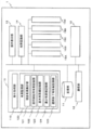
- FIG. 1 is an overall configuration diagram showing the overall configuration of the monitoring system according to the embodiment.
- the monitoring system 5 includes a plurality of automatic transaction apparatuses 1-1 to 1-n (n is an integer) and a server 2.
- the network 3 is a communication network that communicates between the automatic transaction apparatuses 1-1 to 1-n and the server 2, and for example, a LAN or a public network line can be applied. Since the network 3 is a communication network connected to the automatic transaction apparatuses 1-1 to 1-n that handle cash, it is desirable to apply a communication protocol with high security.
- the automatic transaction apparatuses 1-1 to 1-n perform transaction processing such as deposit transactions and withdrawal transactions.
- an ATM Automatic Teller Machine
- the automatic transaction apparatuses 1-1 to 1-n are installed, for example, in branches of financial institutions and the like, stores such as stations and convenience stores, stations, airports, and the like.
- a plurality of automatic transaction apparatuses 1-1 to 1-n may be installed in the same store, or only one device may be installed in the same store. In the following, when the configuration and operation common to the automatic transaction apparatuses 1-1 to 1-n are described, they are expressed as "automatic transaction apparatus 1."
- Each automatic transaction apparatus 1 totals the amount of cash stored in the bill cassettes 15A to 15E (see FIG. 2) and the coin storage 16 (see FIG. 2) mounted on itself, The amount information is notified to the server 2 constantly or periodically.
- the server 2 receives cash amount information from each of the plurality of automatic transaction apparatuses 1-1 to 1-n at all times or regularly, and based on the received cash amount information, the cash of each automatic transaction apparatus 1 Monitor high and low information.
- the server 2 stores the cash amount information of each automatic transaction apparatus 1 in the storage unit 21 (see FIG. 3).
- the server 2 is connected to a display unit 22 (see FIG. 3) such as a display, and can display a display screen including transition of cash amount information of each automatic transaction apparatus 1 being monitored. Thereby, an operator such as a maintenance company can recognize the transition of the cash amount information of each automatic transaction apparatus 1.
- a display unit 22 see FIG. 3
- an operator such as a maintenance company can recognize the transition of the cash amount information of each automatic transaction apparatus 1.
- the detailed description of the display method of the transition of cash amount information of each automatic transaction apparatus 1 by the server 2 will be described later, instead of displaying only the cash amount at a certain point in time, for example, each automatic transaction in one day
- the value of the cash amount at the start of the service of the device 1 and the value of the cash amount at the end of the service, and the maximum amount and the minimum amount in one day can be recognized. Thereby, since the operator can recognize the fluctuation
- FIG. 2 is an internal configuration diagram showing a configuration of a control system of the automatic transaction apparatus 1 according to the embodiment.
- the automatic transaction apparatus 1 includes a control unit 10, a storage unit 11, a communication unit 12, an operation display unit 13, a banknote recognition unit 14, banknote cassette units 15A to 15E, and a coin storage unit 16.
- the bill cassette units 15A to 15E are mounted on the lower unit of the automatic transaction apparatus 1 and store bills for each denomination.
- Each of the banknote cassette units 15A to 15E includes, for example, a deposit-only cassette having a banknote stacking function, a withdrawal-dedicated cassette having a banknote feeding function, a reflux type recycling cassette (payment / withdrawal) having both banknote stacking function and banknote feeding function. Applicable cassettes) can be applied.
- each of the banknote cassettes 15A to 15E is a reflux type recycling cassette.
- each banknote cassette 15A to 15E can not only deposit banknotes but also dispense banknotes that have been deposited. Therefore, when a deposit transaction is performed, the number of stored sheets stored in each banknote cassette section 15A to 15E. When the withdrawal transaction is performed, the number of stored sheets stored in each of the banknote cassette units 15A to 15E decreases.
- the coin storage unit 16 is mounted on the lower unit of the automatic transaction apparatus 1 and stores coins for each denomination.
- the control unit 10 is responsible for various functions that can be executed by the automatic transaction apparatus 1. For example, the control unit 10 controls various transaction processes of the automatic transaction apparatus 1, determines the presence / absence of a failure in various components mounted on the automatic transaction apparatus 1, and is stored in the automatic transaction apparatus 1. The amount of cash including the banknotes and coins is totaled, and the total cash amount information is transmitted to the server 2.
- control part 10 implement
- Various functions may be constructed by installing the processing program.
- the processing program can be shown as a functional block illustrated in FIG.
- the control unit 10 includes a transaction processing unit 110 and a height monitoring unit 120 as shown in FIG.
- the transaction processing unit 110 processes various transactions such as a deposit transaction and a withdrawal transaction in the automatic transaction apparatus 1.
- the transaction processing unit 110 displays a transaction screen of the transaction type instructed through the operation display unit 13 of the automatic transaction apparatus 1 on the operation display unit 13 and performs the transaction process.
- the transaction amount monitoring unit 120 monitors the amount of cash stored in the bill cassette units 15A to 15E and the coin storage unit 16 mounted on the automatic transaction apparatus 1, and transmits the information on the amount of cash to the server 2.
- the high / low monitoring unit 120 includes a cash high / low totaling unit 121, an operation start high / low recording unit 122, a maximum high / low price recording unit 123, a minimum high / high price recording unit 124, and an operation end high / low record. Part 125.
- the cash amount totaling unit 121 collects the cash amount stored in each of the banknote cassette units 15A to 15E and the cash amount stored in the coin storage unit 16 at all times or regularly, and automatically transaction apparatus 1 Cash totals stored in the whole are counted.
- the summing timing by the cash amount tallying section 121 is performed at the start of service operation of the automatic transaction apparatus 1 and at the end of service operation. Further, the cash amount totaling unit 121 always counts and monitors the amount of cash in the automatic transaction apparatus 1 from the time when the service operation is started to the time when the service operation is completed.
- the method for counting cash amount by the cash amount counting unit 121 collects the amount of cash amount for each denomination. And cash amount totaling part 121 totals the cash amount for every denomination, and totals the total amount of cash amount at each time.
- the cash amount totaling unit 121 generally counts the number of banknotes stored in each of all the banknote cassette units 15A to 15E for each denomination, or the coin storage unit 16 Count for each denomination stored in the bank, and add up cash.
- the cash amount totaling unit 121 totals the cash amount at the end of operation based on the number of stored banknotes for each denomination of the banknote cassette units 15A to 15E and the number of stored coins for each denomination of the coin storage unit 16.
- the amount of cash at the end of service operation on the previous day may be used.
- the cash amount totaling unit 121 is deposited or withdrawn by the banknote recognition unit 14.
- the number of banknotes obtained for each denomination is acquired, and the number of banknotes counted by the banknote recognition unit 14 is added to or subtracted from the number of stored banknotes for each denomination, and the number of stored banknotes for each denomination is obtained each time a transaction is completed.
- cash amount totaling part 121 can total cash amount at the time of transaction completion for every transaction completion.
- the banknote cassette units 15A to 15E and the coin storage unit 16 have a function of counting the number of stored items for each denomination. Accordingly, the cash amount totaling unit 121 obtains the cash amount based on the number of stored moneys for each denomination notified from the banknote cassette units 15A to 15E and the coin storage unit 16.
- the cash amount totaling unit 121 transmits cash amount information to the server 2.
- the timing at which the cash amount totaling unit 121 transmits the cash amount information to the server 2 is, for example, at the start of daily operation, such as at the end of service operation, the maximum high value, the minimum high value, and the minimum
- the cash amount information including these four cash amounts may be transmitted to the server 2 when the value and the four amounts at the end of operation are obtained.
- the cash amount information is information including the cash amount of the automatic transaction apparatus 1.
- the cash amount information includes, for example, the above-mentioned amount at the start of operation on the day, the maximum amount, the minimum amount, four cash values at the end of operation, and information indicating the installation location of the automatic transaction apparatus 1 (For example, a branch name or a branch number) and identification information indicating the automatic transaction apparatus 1 (for example, a number of the automatic transaction apparatus 1).
- the cash amount information is not limited to the information exemplified above, and may include other types of information.
- the operation start amount recording unit 122 stores, in the storage unit 11, the amount of cash collected by the cash amount totaling unit 121 when the service operation is started.
- the maximum stock value recording unit 123 stores the maximum value of cash stock that fluctuates in a predetermined period (for example, one day) in the storage unit 11.
- the maximum high value recording unit 123 records the maximum high value in the automatic transaction apparatus 1 with the cash value at the start of operation as the initial value of the maximum high value. That is, when the cash value calculated by the cash value totaling unit 121 exceeds the maximum value due to the transaction executed after the operation is started, the maximum value is updated.
- the minimum high / low price recording unit 124 stores the minimum high / high value of the cash price that fluctuates in a predetermined period (for example, one day) in the storage unit 11.
- the minimum high / low price recording unit 124 records the minimum high / high price in the automatic transaction apparatus 1 using the cash high / low value at the start of operation as an initial value of the minimum high / high price. In other words, when the cash amount calculated by the cash amount totaling unit 121 becomes less than the minimum value due to the transaction executed after the operation is started, the minimum value is updated.
- the maximum high value recording unit 123 and the minimum high value recording unit 124 are configured so that the maximum high value and the minimum value are determined based on the cash high value at the completion of the transaction for each transaction completed between the start of operation and the end of operation. Update the high price.
- the maximum peak value recording unit 123 and the minimum peak value recording unit 124 may obtain the maximum peak value and the minimum peak value in a predetermined period. For example, the busy time in which the automatic transaction apparatus 1 is frequently used in one day is set, and the maximum peak value recording unit 123 and the minimum peak value recording unit 124 set the maximum peak value and the minimum peak value in the set busy time. You may make it ask.
- the operation amount recording unit 125 stores the cash amount collected at the end of service operation in the storage unit 11 by the cash amount totaling unit 121.
- the storage unit 11 stores a processing program executed by the control unit 10, history information of each transaction, display screen information necessary for transaction processing, cash amount information, and the like.
- the communication unit 12 transmits cash amount information to the server 2 under the control of the control unit 10.
- the operation display control unit 13 displays a display screen or receives information input by a customer operation under the control of the control unit 10.
- the banknote recognition unit 14 counts the number of banknotes inserted in the deposit transaction and the number of banknotes to be withdrawn in the withdrawal transaction, and determines the authenticity of the banknote.
- the banknote recognition unit 14 notifies the control unit 10 of the counting result.
- FIG. 3 is an internal configuration diagram showing an internal configuration of the server 2 according to the embodiment.
- the server 2 includes a control unit 20, a storage unit 21, a display unit 22, an operation unit 23, and a communication unit 24.
- the server 2 has the same hardware configuration as an existing server computer.
- the communication unit 24 exchanges information with each automatic transaction apparatus 1 through the network 3.
- the control unit 20 monitors the cash amount information of each automatic transaction apparatus 1.
- the control part 20 implement
- Various functions may be constructed by installing the processing program.
- the processing program can be shown as a functional block illustrated in FIG.
- the control unit 20 includes a height information acquisition unit 201, a height information generation unit 202, and a display control unit 203.
- the high-value information acquisition unit 201 acquires cash high-value information from each automatic transaction apparatus 1 through the communication unit 23.
- the stock information acquisition unit 201 stores the acquired cash stock information in the storage unit 21.
- the yield information generation unit 202 generates the yield information indicating the transition of the cash yield of each automatic transaction apparatus 1 based on the yield information stored in the storage unit 21.
- the height information generation unit 202 indicates the daily maximum value and the minimum value at the start of operation and at the end of operation, and the daily maximum value and minimum value.
- Information on the amount of money including “information” and “period transition information” for a predetermined period (for example, January, 3 months, 1 year, etc.) is displayed.
- the height information generating unit 202 may display the height information of each automatic transaction apparatus 1 in a table format, or may display it in a graph format so that it can be easily visually recognized. .
- the display control unit 203 displays the height information generated by the height information generation unit 202 on the display unit 22.
- the display control unit 203 displays the height information obtained by processing the height information on the display unit 22 in accordance with the designation information obtained through the operation unit 23. For example, when the branch number designated by the operator operation or the identification number of the automatic transaction apparatus 1 is input through the operation unit 23, the display control unit 203 performs all or a part of the automatic transaction installed in the designated branch.
- the display control unit 203 When the height information of the apparatus 1 is displayed, or when an instruction to change the display format is input from the operation unit 23, the information converted into the specified format is displayed on the display unit 22.
- the storage unit 21 stores a control program of the control unit 20, data necessary for program processing, and cash amount information of each automatic transaction apparatus 1.
- the display unit 22 is, for example, a display, and displays the height information under the control of the control unit 10. For example, the operator can recognize the transition of the cash amount of each automatic transaction apparatus 1 by looking at the amount information displayed on the display unit 22. In addition, if necessary, the operator can give an instruction to dispatch a staff member for cash replenishment or cash collection.
- the operation unit 23 is, for example, a keyboard or a numeric keypad, and receives an operator's operation to specify the branch number for displaying the high-price information displayed on the display unit 22, the specification of the automatic transaction apparatus 1, the specification of the display format, and the like.
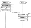
- FIG. 4 is a sequence showing the high / low transition status monitoring process of the automatic transaction apparatus 1 according to the embodiment.
- each automatic transaction apparatus 1 the power is turned on, and when the service operation starts, the cash amount totaling unit 121 records the cash amount in the automatic transaction apparatus 1 when the service operation starts (S101).
- the cash amount totaling unit 121 totals the cash amount at the completion of the transaction every time the transaction is completed.
- the maximum high value recording unit 123 and the minimum high value recording unit 124 record the maximum high value and the minimum high value in one day based on the cash value calculated by the cash value totaling unit 121 (S102).
- the maximum high value recording unit 123 sets the high value at the start of operation as the initial value of the maximum high value
- the minimum high value recording unit 124 sets the high value at the start of operation as the initial value of the minimum high value.
- the amount of cash is changed by the transaction after the start of operation.
- Each banknote cassette 15A to 15E according to the embodiment is a reflux type recycling cassette. Accordingly, when a deposit transaction is performed, the number of sheets stored in the banknote cassettes 15A to 15E increases, so that the amount of cash increases. On the other hand, when the withdrawal transaction is performed, the number of banknote cassettes 15A to 15E is reduced, so that the amount of cash is also reduced.
- the amount of cash varies depending on the deposit transaction and withdrawal transaction.
- the maximum high value recording unit 123 and the minimum high value recording unit 124 set the high value at the start of operation as the initial value of the maximum high value and the minimum high value, the high value that fluctuates in subsequent transactions, the maximum high value, The minimum high value is compared and the maximum high value and the minimum high value are updated and recorded. Thereby, not only the cash amount at a certain point of time, but also the maximum value and the minimum value of the fluctuating value in the day can be monitored.
- the maximum high / low price recording unit 123 and the minimum high / high price recording unit 124 observes the cash high / low value within a predetermined time, which is a short period of time, and monitors the maximum high / low value of the day. It may be. That is, as a general tendency of the usage situation of the automatic transaction apparatus 1, it may be frequently used in a certain time zone. Therefore, the maximum height value and the minimum height value in the automatic transaction apparatus 1 can be obtained by observing the maximum height value and the minimum height value in the frequently used time zone.
- the busy period of the automatic transaction apparatus 1 varies depending on the automatic transaction apparatus 1 depending on the branch where the automatic transaction apparatus 1 is installed, the installation location of the automatic transaction apparatus 1 in the branch, and the like. Therefore, the setting of the observation time for observing the maximum height value and the minimum height value may be different for each automatic transaction apparatus 1.
- the cash amount totaling unit 121 records the cash amount in the automatic transaction apparatus 1 at the end of service operation (S103).
- the value monitoring unit 120 displays the cash value information including the value at the start of operation, the value at the end of operation, the maximum value, and the minimum value. 2 (S104).
- the server 2 receives cash amount information from each automatic transaction apparatus 1, acquires the received cash amount information of the nuclear automatic transaction apparatus 1, and stores each cash amount information for each automatic transaction apparatus 1. (S105).
- the height information generation unit 202 generates height information indicating the transition status of the height based on the height information of the nuclear automatic transaction apparatus 1 stored in the storage unit 21 (S106).
- FIG. 5 is a flowchart showing the processing for generating height information indicating the height transition status according to the embodiment.
- FIG. 6 is an explanatory diagram illustrating an example of the daily amount information according to the embodiment.
- FIG. 7 is an explanatory diagram for explaining an example of the amount-of-period information according to the embodiment. The process of S106 will be described with reference to FIGS.
- the cash value information generation unit 202 reads the cash value information of each automatic transaction apparatus 1 from the storage unit 21, and based on the cash value at the start of operation and the cash value at the end of operation, It is confirmed whether or not the height has increased (S201).
- the height information generation unit 202 determines the color of the height chart for each day to be displayed according to whether or not the daily height has increased (S202).
- the yield information generating unit 202 creates daily yield information based on the height value at the start of operation, the height value at the end of operation, the maximum height value, and the minimum height value included in the cash amount information. (S203).
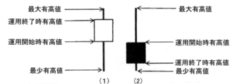
- FIG. 6 is an example of daily high / low information.
- the high / low information generation unit 202 includes a high value at the start of operation, a high value at the end of operation, a maximum high value, and a minimum value.
- the fluctuation of the daily high value is displayed with a candlestick (box whiskers) using the high value.
- Fig. 6 (1) is a candlestick that displays fluctuations in daily highs when daily highs increase.
- the case where the amount of money per day increases is, for example, when the banknote cassettes 15A to 15E are replenished with cash, or when a large amount of cash is deposited through one-day transactions.
- a candlestick including a white box is used as shown in FIG.
- Fig. 6 (2) is a candlestick that displays the fluctuation of the daily high value when the daily high value decreases.
- the case where the daily amount decreases is, for example, a case where cash is collected from the banknote cassettes 15A to 15E, or a case where a large amount of cash is withdrawn through a daily transaction.
- a candlestick including a black box is used as shown in FIG.
- the color of the box shown in FIG. 6 (1) and FIG. 6 (2) is color-coded in order to distinguish the increase / decrease in the amount of daily stock, and is not particularly limited.
- the color of the box in FIG. 6 (1) may be green, or the color of the box in FIG. 6 (2) may be red.
- the height information generation unit 202 forms a white box as shown in FIG. 6 (1), where the upper part of the box is the highest value at the end of operation, and the lower part of the box is The high value at the start of operation. Further, the upper end of the line extending to the upper side of the box is the maximum height value, and the lower end of the line extending to the lower side of the box is the minimum height value.
- the height information generation unit 202 forms a black box as shown in FIG. 6 (2), and the upper part of the box indicates the height at the start of operation, The bottom is the high value at the end of operation. Further, the upper end of the line extending to the upper side of the box is the maximum height value, and the lower end of the line extending to the lower side of the box is the minimum height value.
- the stock information generating unit 202 generates period transition information using the stock information for each past day (S204).
- the display control unit 203 displays the height information indicating the height change over a predetermined period generated by the height information generation unit 202 on the display unit 22 (S ⁇ b> 104).
- the height information generation unit 202 uses the daily height information indicating the daily height change status of the automatic transaction apparatus 1 to change the height information over a predetermined period.
- the period transition information shown is generated.
- the vertical axis indicates the amount of cash and the horizontal axis indicates the date. As shown in FIG. 7, it is possible to display fluctuations in the amount of money every day and fluctuations in the amount of money over a period of one month.
- the operator is performed by the automatic transaction apparatus 1. It is possible to recognize the status of the transaction, that is, whether the deposit transaction or the withdrawal transaction is frequently performed, the amount of cash deposited is large, and the amount of cash dispensed is small.
- the operator may receive an operation through the operation unit 23 to display, for example, the high and low transition status at the same time in the previous year at the same time.
- the display control unit 203 may read past high-end information from the storage unit 21 and display the information. As a result, the operator can predict the future trend of the amount of gains based on the results of the same year in the previous year and the current trend in the current year.
- the server displays daily fluctuations in the amount of money with candlesticks, and displays the change in the amount of money for a predetermined period.
- the display screen displayed on the display unit is not limited to those displayed in FIGS.
- the yield information generating unit 23 aggregates all the yield information of the plurality of automatic transaction apparatuses 1 installed in a certain branch, and displays the transition status of the corresponding branch. You may do it. As a result, the operator can recognize the state of transition of the amount of money for each branch, and therefore can predict the dispatch timing of the staff to be dispatched to the branch for each branch.
- the cash amount information transmitted to the server by the automatic transaction apparatus includes all the cash amounts stored in the plurality of banknote cassette units and the coin storage unit.
- the cash amount information may include the amount information of banknotes stored in a plurality of banknote cassette units.
- the cash amount information may be information for each denomination. Thereby, the operator can grasp
Landscapes
- Business, Economics & Management (AREA)
- Accounting & Taxation (AREA)
- Physics & Mathematics (AREA)
- General Physics & Mathematics (AREA)
- Finance (AREA)
- Engineering & Computer Science (AREA)
- Strategic Management (AREA)
- General Business, Economics & Management (AREA)
- Theoretical Computer Science (AREA)
- Economics (AREA)
- Marketing (AREA)
- Development Economics (AREA)
- Technology Law (AREA)
- Financial Or Insurance-Related Operations Such As Payment And Settlement (AREA)
Abstract
本発明に係るサーバは、複数の現金処理装置のそれぞれから取得した、複数時点での現金有高の変動を含む現金有高情報を記憶する記憶部と、記憶部の各現金処理装置の現金有高情報に基づいて、各現金処理装置における複数時点での現金有高の変動を示す有高情報を生成する有高情報生成部と、有高情報生成部により生成された現金有高の推移情報を示す有高情報を出力する有高情報出力部とを備えることを特徴とする。
Description
本発明は、サーバ、監視システム及び現金処理装置に関し、例えば、金融機関等に設置されているATM(Automatic Teller Machine)等の現金処理装置、各現金処理装置内の現金の収納状態を監視するサーバ及び監視システムに適用し得るものである。
例えば、現金処理装置内の現金の有高が不足したり又は満杯になったりする場合、係員が出動して、現金補充又は現金回収等の対応が必要となる。そのため、複数の現金処理装置のそれぞれから現金有高に関する情報を取得して、各現金処理装置内の現金有高データを管理する方法がある(特開2011-11343号公報、特開2014-178780号公報参照)。
特開2011-11343号公報の記載技術は、現金預け払い機の取引情報を取得し、その取引情報に基づいて、入金と出金との差分を積算していき、必要資金量を予測して表示するものである。
特開2014-178780号公報の記載技術は、入出金機の締めデータを取得して、前日の有高データと本日の締めデータと、現金の回収の有無等の情報に基づいて、現在の有高を算出するものである。
上記のように、従来技術は、現金処理装置のサービス開始時点や終了時点等のような、ある時点における現金の保有量を現金処理装置から取得して、日次で現金有高を算出して表示している。
しかしながら、上述した従来技術は、1日における現金処理装置の現金保有量の変化をサービス開始値と終了値で表示するというものである。つまり、その日の一時的な最大有高及び最少有高まで認識できないため、将来の有高を予測する際に、サービスに必要となる各日の必要最大保有量や必要最大空き容量まで算出できないという課題がある。
また、1日の中で最も取引量が多いと予測される時間帯における最適な有高を算出できないという課題もある。
さらに、現金補充又は現金回収を行う係員の出動回数を減らし、現金補充又は回収を効率的に行うことが望まれている。
そのため、各現金処理装置の現金有高の推移傾向を的確に認識でき、現金の飽和時期や不足時期を予測でき、係員の出動回数を減らすことができるサーバ、監視システム及び現金処理装置が求められている。
かかる課題を解決するために、第1の本発明に係るサーバは、(1)複数の現金処理装置のそれぞれから取得した、複数時点での現金有高の変動を含む現金有高情報を記憶する記憶部と、(2)記憶部の各現金処理装置の現金有高情報に基づいて、各現金処理装置における複数時点での現金有高の変動を示す有高情報を生成する有高情報生成部と、(3)有高情報生成部により生成された現金有高の推移情報を示す有高情報を出力する有高情報出力部とを備えることを特徴とする。
第2の本発明に係る監視システムは、それぞれ、複数の時点の現金有高を監視して、現金有高の変動を含む現金有高情報を管理する複数の現金処理装置と、各現金処理装置から取得した現金有高情報を取得するサーバとを備える監視システムにおいて、サーバは、複数の現金処理装置のそれぞれから取得した、複数時点での現金有高の変動を含む現金有高情報を記憶する記憶部と、記憶部の各現金処理装置の現金有高情報に基づいて、各現金処理装置の複数時点での現金有高の変動を示す有高情報を生成する有高情報生成部と、有高情報生成部により生成された現金有高の推移情報を示す有高情報を出力する有高情報出力部とを備えることを特徴とする。
第3の本発明に係る現金処理装置は、所定の現金処理を行なう現金処理装置において、(1)複数の時点で現金有高を集計する現金有高集計部と、(2)現金有高集計部により集計された複数の時点での現金有高の変動を含む現金有高情報を外部に送信する通信部とを備えることを特徴とする。
本発明によれば、各現金処理装置の現金有高の推移傾向を的確に認識でき、現金の飽和時期や不足時期を予測でき、係員の出動回数を減らすことができる。
(A)主たる実施形態
以下では、本発明に係るサーバ、監視システム及び現金処理装置の実施形態を、図面を参照しながら詳細に説明する。
以下では、本発明に係るサーバ、監視システム及び現金処理装置の実施形態を、図面を参照しながら詳細に説明する。
この実施形態では、本発明を適用して、金融機関等に設置されているATM(自動取引装置)の現金収納状態を監視する監視システムに適用する場合を例示する。
(A-1)実施形態に係る構成
(A-1-1)全体構成
図1は、実施形態に係る監視システムの全体構成を示す全体構成図である。
(A-1-1)全体構成
図1は、実施形態に係る監視システムの全体構成を示す全体構成図である。
図1において、監視システム5は、複数の自動取引装置1-1~1-n(nは整数)、サーバ2を有する。
なお、ネットワーク3は、各自動取引装置1-1~1-nとサーバ2との間を通信する通信網であり、例えば、LANや公衆網回線等を適用できる。ネットワーク3は、現金を取り扱う自動取引装置1-1~1-nと接続する通信網であるため、高いセキュリティが施された通信プロトコルを適用したものが望ましい。
自動取引装置1-1~1-nは、入金取引や出金取引等の取引処理を行なうものであり、例えば、ATM(Automatic Teller Machine)、通帳記帳機、両替機等を適用できる。自動取引装置1-1~1-nは、例えば、金融機関等の各支店の店舗、駅やコンビニエンスストア等の店舗、駅構内、空港構内等に設置される。なお、同じ店舗に複数台の自動取引装置1-1~1-nが設置されていても良いし、同じ店舗に1台のみ設置されているものであっても良い。なお、以下では、自動取引装置1-1~1-nに共通する構成及び動作を説明するときには、「自動取引装置1」と表現する。
各自動取引装置1は、自身に搭載されている紙幣カセット15A~15E(図2参照)及び硬貨収納庫16(図2参照)に収納されている現金の有高を集計し、集計後の現金有高情報を、常時又は定期的に、サーバ2に通知する。
サーバ2は、複数の自動取引装置1-1~1-nのそれぞれから現金有高情報を、常時又は定期的に受信し、受信した現金有高情報に基づいて、各自動取引装置1の現金有高情報を監視する。サーバ2は、各自動取引装置1の現金有高情報を記憶部21(図3参照)に記憶する。
サーバ2は、ディスプレイ等の表示部22(図3参照)と接続しており、監視している各自動取引装置1の現金有高情報の推移を含む表示画面を表示できる。これにより、保守会社等のオペレータは、各自動取引装置1の現金有高情報の推移を認識できる。サーバ2による各自動取引装置1の現金有高情報の推移の表示方法の詳細な説明は後述するが、ある時点での現金有高のみを表示するのではなく、例えば、1日における各自動取引装置1のサービス開始時の現金有高及び終了時の現金有高の値と、1日における最大有高及び最少有高とが認識できるようにする。これにより、オペレータは、各自動取引装置1の1日における現金有高の変動を認識できるため、その自動取引装置1に保有させるべき現金保有量を予測できる。
(A-1-2)自動取引装置1の詳細な構成
図2は、実施形態に係る自動取引装置1の制御系の構成を示す内部構成図である。
図2は、実施形態に係る自動取引装置1の制御系の構成を示す内部構成図である。
図2において、自動取引装置1は、制御部10、記憶部11、通信部12、操作表示部13、紙幣認識部14、紙幣カセット部15A~15E、硬貨収納部16を有する。
紙幣カセット部15A~15Eは、自動取引装置1の下部ユニットに搭載されており、紙幣を金種毎に収納するものである。各紙幣カセット部15A~15Eは、例えば、紙幣集積機能を有する入金専用カセット、紙幣繰り出し機能を有する出金専用カセット、紙幣集積機能及び紙幣繰り出し機能の両方の機能を有する還流型リサイクルカセット(入出金対応カセット)等を適用できる。
この実施形態では、各紙幣カセット15A~15Eが、還流型リサイクルカセットである場合を例示する。すなわち、各紙幣カセット15A~15Eは、紙幣の入金だけでなく、入金された紙幣を出金することもできるため、入金取引が行なわれると、各紙幣カセット部15A~15Eに収納される収納枚数が増え、出金取引が行なわれると、各紙幣カセット部15A~15Eに収納される収納枚数が減ることになる。
硬貨収納部16は、自動取引装置1の下部ユニットに搭載されており、硬貨を金種毎に収納するものである。
制御部10は、自動取引装置1が実行可能な各種機能を司るものである。例えば、制御部10は、自動取引装置1の各種取引処理を制御したり、自動取引装置1に搭載される各種構成要素の障害の有無を判断したり、自動取引装置1内に収納されている、紙幣及ぶ硬貨を含む現金の有高を集計し、その集計した現金有高情報をサーバ2に送信したりする。
なお、制御部10は、例えば、CPUが、ROMに格納される処理プログラムを実行することにより自動取引装置1の各種機能を実現する。処理プログラムがインストールされることで各種機能が構築されるようにしても良く、その場合、処理プログラムは図2に例示する機能ブロックとして示すことができる。
制御部10は、図2に示すように、取引処理部110、有高監視部120を有する。
取引処理部110は、自動取引装置1における入金取引や出金取引等の各種取引の処理を行なうものである。取引処理部110は、自動取引装置1の操作表示部13を通じて指示された取引種類の取引画面を操作表示部13に表示し、当該取引処理を行なう。
有高監視部120は、自動取引装置1に搭載される紙幣カセット部15A~15E、硬貨収納部16に収納されている現金有高を監視し、その現金有高情報をサーバ2に送信する。
図2に示すように、有高監視部120は、現金有高集計部121、運用開始時有高記録部122、最大有高値記録部123、最少有高値記録部124、運用終了時有高記録部125を有する。
現金有高集計部121は、常時又は定期的に、各紙幣カセット部15A~15Eに収納される現金有高と、硬貨収納部16に収納される現金有高とを収集して、自動取引装置1全体に収納されている現金有高を集計する。
ここで、現金有高集計部121による集計タイミングは、自動取引装置1のサービス運用開始時及びサービス運用終了時に行なう。さらに、現金有高集計部121は、サービス運用開始時からサービス運用終了時までの間で、常時、自動取引装置1内の現金の有高を集計して監視する。
また、現金有高集計部121による現金有高の集計方法は、金種毎に現金有高の額を収集する。そして、現金有高集計部121は、金種毎の現金有高を合計して、各時点の現金有高の総額を集計する。
例えば、サービス運用終了時には、一般的に、現金有高集計部121は、すべての紙幣カセット部15A~15Eのそれぞれに収納されている紙幣の枚数を金種毎に計数したり、硬貨収納部16に収納されている金種毎に計数したりして、現金有高を集計する。現金有高集計部121は、各紙幣カセット部15A~15Eの金種毎の収納枚数や硬貨収納部16の金種毎の収納枚数に基づいて、運用終了時の現金有高を集計する。
また例えば、サービス運用開始時は、現金補充又は回収がなされていない場合には、前日のサービス運用終了時の現金有高としてもよい。
さらに、サービス運用開始時からサービス運用終了時までの間に、入金取引や出金取引の取引が行われると、現金有高集計部121は、紙幣認識部14により計数された入金又は出金された紙幣枚数を金種毎に取得し、金種毎の収納枚数に紙幣認識部14により計数された紙幣枚数を加減又は減算して、取引完了毎に、金種毎の収納枚数を求める。これにより、現金有高集計部121は、取引完了時における現金有高を取引完了毎に集計できる。
また、取引中における現金有高の集計方法の別の方法としては、紙幣カセット部15A~15Eや硬貨収納部16は、金種毎の収納枚数を計数する機能を有している。従って、現金有高集計部121は、紙幣カセット部15A~15E、硬貨収納部16から通知される金種毎の収納枚数に基づいて、現金有高を求める。
また、現金有高集計部121は、現金有高情報をサーバ2に送信する。ここで、現金有高集計部121が、現金有高情報をサーバ2に送信するタイミングは、例えば、サービス運用終了時等のように、1日の運用開始時の有高、最大有高値、最少有高値、運用終了時の4つの有高が得られた時点で、これら4つの現金有高を含む現金有高情報をサーバ2に送信するようにしてもよい。
ここで、現金有高情報は、当該自動取引装置1の現金有高を含む情報である。現金有高情報は、例えば、上述した1日の運用開始時の有高、最大有高値、最少有高値、運用終了時の4つの現金有高の値、自動取引装置1の設置場所を示す情報(例えば、支店名若しくは支店番号など)、自動取引装置1を示す識別情報(例えば、自動取引装置1の番号等)を含む情報である。なお、現金有高情報は、上記に例示した情報に限定されるものではなく、他の種類の情報を含むようにしても良い。
運用開始時有高記録部122は、現金有高集計部121によりサービス運用開始時に集計された現金有高を記憶部11に記憶する。
最大有高値記録部123は、所定期間(例えば1日等)において変動する現金有高の最大値を記憶部11に記憶する。最大有高値記録部123は、運用開始時の現金有高の値を最大有高値の初期値として、自動取引装置1における最大有高値を記録する。つまり、運用開始後の実施される取引により、現金有高集計部121により算出された現金有高値が最大有高値を超える場合には、最大有高値を更新する。
最少有高値記録部124は、所定期間(例えば1日等)において変動する現金有高の最少有高値を記憶部11に記憶する。最少有高値記録部124は、運用開始時の現金有高の値を最少有高値の初期値として、自動取引装置1における最少有高値を記録する。つまり、運用開始後の実施される取引により、現金有高集計部121により算出された現金有高値が最少有高値未満となった場合には、最少有高値を更新する。
最大有高値記録部123及び最少有高値記録部124は、運用開始時から運用終了時までの間に実施される取引完了毎に、取引完了時の現金有高値に基づいて、最大有高値及び最少有高値の更新を行なう。
また、最大有高値記録部123及び最少有高値記録部124は、所定期間における最大有高値及び最少有高値を求めるようにしてもよい。例えば、1日において自動取引装置1が頻繁に利用される繁忙時間が設定され、最大有高値記録部123及び最少有高値記録部124は、設定された繁忙時間における最大有高値及び最少有高値を求めるようにしてもよい。
運用終了時有高記録部125は、現金有高集計部121によりサービス運用終了時に集計された現金有高を記憶部11に記憶する。
記憶部11は、制御部10により実行される処理プログラム、各取引の履歴情報、取引処理に必要な表示画面情報、現金有高情報等を記憶するものである。
通信部12は、制御部10の制御の下、サーバ2に現金有高情報を送信するものである。
操作表示制御部13は、制御部10の制御の下、表示画面を表示したり、顧客操作により入力された情報を受け付けたりする。
紙幣認識部14は、入金取引で投入された紙幣枚数や出金取引で出金すべき紙幣枚数を計数したり、紙幣の真偽判定等をしたりするものである。紙幣認識部14は、計数結果を制御部10に通知する。
(A-1-3)サーバ2の詳細な構成
図3は、実施形態に係るサーバ2の内部構成を示す内部構成図である。
図3は、実施形態に係るサーバ2の内部構成を示す内部構成図である。
図3において、実施形態に係るサーバ2は、制御部20、記憶部21、表示部22、操作部23、通信部24を有する。なお、サーバ2は、既存のサーバコンピュータと同様のハードウェア構成を備える。
通信部24は、ネットワーク3を通じて各自動取引装置1との間で情報の授受を行なうものである。
制御部20は、各自動取引装置1の現金有高情報を監視するものである。なお、制御部20は、例えば、CPUが、ROMに格納される処理プログラムを実行することによりサーバ2の各種機能を実現する。処理プログラムがインストールされることで各種機能が構築されるようにしても良く、その場合、処理プログラムは図3に例示する機能ブロックとして示すことができる。
制御部20は、図3に示すように、有高情報取得部201、有高情報生成部202、表示制御部203を有する。
有高情報取得部201は、通信部23を通じて、各自動取引装置1から現金有高情報を取得するものである。有高情報取得部201は、取得した現金有高情報を記憶部21に記憶する。
有高情報生成部202は、記憶部21に記憶されている有高情報に基づいて、各自動取引装置1の現金有高の推移を示す有高情報を生成する。ここで、有高情報生成部202は、自動取引装置1毎に、1日の運用開始時及び運用終了時、並びに、1日の有高最大値及び有高最少値を示す「日ごと有高情報」と、所定期間(例えば1月、3か月、1年等)の「期間推移情報」とを含む有高情報を表示する。
なお、有高情報生成部202は、各自動取引装置1の有高情報を表形式で表示するようにしてもよいし、視覚的に認識しやすいようにグラフ形式で表示するようにしてもよい。
表示制御部203は、有高情報生成部202により生成された有高情報を表示部22に表示する。表示制御部203は、操作部23を通じて得た指定情報に応じて、有高情報を加工した有高情報を表示部22に表示する。例えば、表示制御部203は、操作部23を通じて、オペレータ操作により指定された支店番号や自動取引装置1の識別番号が入力されると、指定された支店に設置される全部又は一部の自動取引装置1の有高情報を表示したり、また操作部23から表示形式の変更指示が入力されると、指定された形式に変換した情報を表示部22に表示したりする。
記憶部21は、制御部20の制御プログラムや、プログラム処理に必要なデータや、各自動取引装置1の現金有高情報を記憶する。
表示部22は、例えばディスプレイであり、制御部10の制御により、有高情報を表示するものである。例えばオペレータは表示部22に表示される有高情報を見て、各自動取引装置1の現金有高の推移を認識できる。また、必要に応じて、オペレータは、現金補充又は現金回収のために、係員の出動指示などを行なうことができる。
操作部23は、例えば、キーボードやテンキーなどであり、オペレータ操作により、表示部22に表示する有高情報を表示する支店番号や自動取引装置1の指定や、表示形式の指定等を受け付ける。
(A-2)実施形態の動作
続いて、実施形態に係る監視システム5における自動取引装置1の有高推移状況監視処理の動作を、図面を参照しながら詳細に説明する。
続いて、実施形態に係る監視システム5における自動取引装置1の有高推移状況監視処理の動作を、図面を参照しながら詳細に説明する。
図4は、実施形態に係る自動取引装置1の有高推移状況監視処理を示すシーケンスである。
まず、各自動取引装置1において、電源がONとなり、サービス運用開始時に、現金有高集計部121は、サービス運用開始時に、自動取引装置1内の現金有高を記録する(S101)。
サービス運用開始後、自動取引装置1において取引が行なわれると、取引完了毎に、現金有高集計部121は、取引完了時の現金有高を集計する。最大有高値記録部123及び最少有高値記録部124は、現金有高集計部121により算出された現金有高に基づいて、1日おける最大有高値及び最少有高値を記録する(S102)。
例えば、最大有高値記録部123は、運用開始時の有高値を最大有高値の初期値とし、最少有高値記録部124は、運用開始時の有高値を最少有高値の初期値として設定する。ここで、運用開始後の取引によって、現金の有高が変更することになる。実施形態に係る各紙幣カセット15A~15Eは、還流型リサイクルカセットである。従って、入金取引が行なわれると、紙幣カセット15A~15Eへの収納枚数が増えるため、現金有高も増加する。一方、出金取引が行なわれると、紙幣カセット15A~15Eの収納枚数が減るため、現金有高も減少する。このように、還流型リサイクルカセットである紙幣カセット15A~15Eが搭載されている自動取引装置1では、入金取引や出金取引により、現金有高も変動することになる。最大有高値記録部123及び最少有高値記録部124は、運用開始時の有高値を最大有高値及び最少有高値の初期値として設定し、その後の取引で変動する有高値と、最大有高値及び最少有高値とを比較して、最大有高値及び最少有高値の値を更新して記録する。これにより、ある時点での現金有高だけでなく、1日における変動する有高の最大有高値及び最少有高値も監視できる。
また、最大有高値記録部123及び最少有高値記録部124は、例えば、ある程度短い期間である所定時間内の現金有高を観測し、その日のうちの最大有高値及び最少有高値を監視するようにしてもよい。つまり、自動取引装置1の利用状況の一般的な傾向として、ある時間帯において頻繁に利用されることがある。そのため、その頻繁に利用される時間帯における最大有高値及び最少有高値を観測することにより、当該自動取引装置1における最大有高値及び最少有高値を求めることができる。なお、この場合、自動取引装置1の繁忙期は、自動取引装置1が設置されている支店や、支店内における自動取引装置1の設置場所等によって、自動取引装置1に応じて個別に異なる。そのため、最大有高値及び最少有高値を観測する観測時間の設定は、自動取引装置1毎に異なるようにしてもよい。
1日の取引時間が終了すると、現金有高集計部121は、サービス運用終了時に、自動取引装置1内の現金有高を記録する(S103)。
運用終了時の現金有高値が記録されると、有高監視部120は、運用開始時の有高値、運用終了時の有高値、最大有高値及び最少有高値を含む現金有高情報を、サーバ2に送信する(S104)。
サーバ2では、各自動取引装置1からの現金有高情報を受信し、受信した核自動取引装置1の現金有高情報を取得し、各現金有高情報を自動取引装置1毎に記憶部21に記憶する(S105)。
サーバ2では、有高情報生成部202が、記憶部21に記憶されている核自動取引装置1の有高情報に基づいて、有高の推移状況を示す有高情報を生成する(S106)。
図5は、実施形態に係る有高推移状況を示す有高情報の生成処理を示すフローチャートである。
図6は、実施形態に係る日ごと有高情報の一例を説明する説明図である。
図7は、実施形態に係る期間有高情報の一例を説明する説明図である。図5~図7を用いて、S106の処理を説明する。
まず、有高情報生成部202は、各自動取引装置1の現金有高情報を記憶部21から読み出し、運用開始時の有高値と、運用終了時の有高値とに基づいて、1日の有高が増加したか否かを確認する(S201)。
有高情報生成部202は、1日の有高が増加したか否かに応じて、表示する日ごと有高のチャートの色を決定する(S202)。
有高情報生成部202は、現金有高情報に含まれている、運用開始時の有高値、運用終了時の有高値、最大有高値及び最少有高値に基づいて、日ごと有高情報を作成する(S203)。
図6は、日ごと有高情報の一例であるが、有高情報生成部202は、図6に例示するように、運用開始時の有高値、運用終了時の有高値、最大有高値及び最少有高値を用いてローソク足(箱ひげ)で、1日の有高値の変動を表示する。
図6(1)は、1日の有高が増加した場合の1日の有高値の変動を表示するローソク足である。1日の有高が増加した場合とは、例えば、紙幣カセット15A~15Eに現金補充された場合や、1日の取引を通じて、現金が多く入金された場合等である。1日の有高が増加した場合、例えば、図6(1)に示すように白色の箱を含むローソク足を用いる。
図6(2)は、1日の有高が減少した場合の1日の有高値の変動を表示するローソク足である。1日の有高が減少した場合とは、例えば、紙幣カセット15A~15Eから現金を回収した場合や、1日の取引を通いて、現金が多く出金された場合等である。1日の有高が減少した場合、例えば、図6(2)に示すように黒色の箱を含むローソク足を用いる。
なお、図6(1)及び図6(2)に示す箱の色は、1日の有高の増減の別を区別するために色分けしたものであり、特に限定されるものではない。例えば、図6(1)の箱の色を緑色にしたり、図6(2)の箱の色を赤色にしたりしてもよい。
S202において1日の有高が増加した場合、有高情報生成部202は、図6(1)に示すように白色の箱とし、その箱の上部が運用終了時の有高値、箱の下部が運用開始時の有高値とする。また、箱の上側に伸びる線の上端が最大有高値、箱の下側に伸びる線の下端が最少有高値とする。
また、S202において1日の有高が減少した場合、有高情報生成部202は、図6(2)に示すように黒色の箱とし、その箱の上部が運用開始時の有高値、箱の下部が運用終了時の有高値とする。また、箱の上側に伸びる線の上端が最大有高値、箱の下側に伸びる線の下端が最少有高値とする。
次に、有高情報生成部202は、過去の日ごと有高情報を用いて、期間推移情報を生成する(S204)。
図4に戻り、表示制御部203は、有高情報生成部202により生成された所定期間に亘る有高推移を示す有高情報を表示部22に表示する(S104)。
図7に示すように、有高情報生成部202は、当該自動取引装置1の日ごとの有高の推移状況を示す日ごと有高情報を用いて、所定期間に亘る有高情報の推移を示す期間推移情報を生成する。
図7に例示するチャートは、縦軸は現金有高の額を示し、横軸は日にちを示している。図7に示すように、1日ごとの有高の変動と、1か月の期間に亘る有高の変動を表示できる。
このように、自動取引装置1の1日の運用開始時及び運用終了時の有高値だけでなく、最大有高値及び最少有高値も表示することで、オペレータは、当該自動取引装置1で行われる取引の状況、すなわち、入金取引又は出金取引のいずれが多く行われているか、入金された現金が多く、出金される現金が少ない等の状況を認識できる。
また例えば、1か月等の所定期間に亘る有高の推移状況を示すことにより、当該自動取引装置1の現金補充又は回収などの周期を予測できるため、係員の出動タイミングを調整できる。
なお、ここでは、1か月の期間における有高推移状況を示している。しかし、操作部23を通じて、オペレータ操作を受けて、例えば、前年の同時期の有高推移状況を同時に表示してもよい。つまり、表示制御部203は、過去の有高情報を記憶部21から読み出して表示するようにしてもよい。これにより、前年の同時期の有高推移状況と現在の有高推移状況とに基づいて、オペレータは、前年の同時期の実績に照らして、今後の有高の推移状況を予測できる。
(A-3)実施形態の効果
以上のように、実施形態によれば、対象とするATMの一定期間における現金有高の推移の傾向を視覚的に把握することができ、これに基づいた現金の飽和時期や不足時期を予測することが可能になるという効果が得られる。
以上のように、実施形態によれば、対象とするATMの一定期間における現金有高の推移の傾向を視覚的に把握することができ、これに基づいた現金の飽和時期や不足時期を予測することが可能になるという効果が得られる。
(B)他の実施形態
上述した実施形態においても種々の変形実施形態を言及したが、本発明は、以下の変形実施形態にも適用できる。
上述した実施形態においても種々の変形実施形態を言及したが、本発明は、以下の変形実施形態にも適用できる。
(B-1)上述した実施形態では、本発明に係る現金処理装置が、ATMに代表される自動取引装置である場合を例示したが、現金を収納して現金処理を行なう装置であれば、自動取引装置に限定されるものではない。
(B-2)上述した実施形態では、サーバが、図6及び図7に例示するように、1日の有高の変動をローソク足で表示し、所定期間の有高の推移状況を示す表示画面を表示部22に表示する場合を例示した。しかし、表示部に表示する表示画面は、図6及び図7に表示するものに限定されるものではない。例えば、従来のように運用開始時及び運用終了時等のように、ある時点の有高のみを表示するのではなく、その日の最大有高値及び最少有高値の変動も表示できるものであれば、ローソク足に限定されない。
(B-3)上述した実施形態では、ある1台の自動取引装置のローソク足のチャートを表示する場合を例示した。しかし、複数台の自動取引装置の有高推移状況を同時に並列表示したり、ある支店に設置されている複数の自動取引装置の有高推移状況を同時に並列表示したりしてもよい。
(B-4)また、有高情報生成部23は、ある支店に設置されている複数の自動取引装置1のすべての有高情報を集計して、当該支店の有高の推移状況を表示するようにしてもよい。これにより、オペレータは、支店毎の有高の推移状況を認識できるため、支店に出動させる係員の出動タイミングを支店毎に予測できる。
(B-5)上述した実施形態では、自動取引装置がサーバに送信する現金有高情報は、複数の紙幣カセット部及び硬貨収納部に収納されるすべての現金有高を含むものとした。しかし、現金有高情報は、複数の紙幣カセット部に収納される紙幣の有高情報を含むものとしてもよい。
また、現金有高情報は、金種毎の有高情報としてもよい。これにより、オペレータは、金種毎の現金有高の推移状況を把握できる。
2016年1月14日に出願された日本国特許出願2016-005399号の開示は、その全体が参照により本明細書に取り込まれる。
Claims (7)
- 複数の現金処理装置のそれぞれから取得した、複数時点での現金有高の変動を含む現金有高情報を記憶する記憶部と、
前記記憶部の前記現金処理装置の各々の現金有高情報に基づいて、現金処理装置の各々における複数時点での現金有高の変動を示す有高情報を生成する有高情報生成部と、
前記有高情報生成部により生成された現金有高の推移情報を示す有高情報を出力する有高情報出力部と
を備えることを特徴とするサーバ。 - 前記有高情報生成部は、第1期間内の現金有高の変動状況と、前記第1期間よりも長い第2期間の有高推移状況とを表す有高情報を生成することを特徴とする請求項1に記載のサーバ。
- 前記現金有高情報は、第1期間内の運用開始時及び運用終了時の有高値と、第1期間内における最大有高値及び最少有高値とを含むものであり、
前記有高情報生成部は、第1期間の運用開始時及び運用終了時の有高値と、第1期間の最大有高値及び最少有高値とを用いて、第1期間内の現金有高の変動状況を生成することを特徴とする請求項2に記載のサーバ。 - 前記現金有高情報に含まれる最大有高値及び最少有高値が、前記現金処理装置の各々の利用頻度に応じた所定期間内のものであることを特徴とする請求項3に記載のサーバ。
- 前記有高情報生成部は、前記第1期間の現金有高の変動状況をローソク足で表示することを特徴とする請求項2~4のいずれか一項に記載のサーバ。
- それぞれ、複数の時点の現金有高を監視して、現金有高の変動を含む現金有高情報を管理する複数の現金処理装置と、
前記現金処理装置の各々から取得した前記現金有高情報を取得するサーバと、
を備える監視システムにおいて、
前記サーバは、
複数の現金処理装置の各々から取得した、複数時点での現金有高の変動を含む現金有高情報を記憶する記憶部と、
前記記憶部の前記現金処理装置の各々の現金有高情報に基づいて、現金処理装置の各々の複数時点での現金有高の変動を示す有高情報を生成する有高情報生成部と、
前記有高情報生成部により生成された現金有高の推移情報を示す有高情報を出力する有高情報出力部と
を備えることを特徴とする監視システム。 - 所定の現金処理を行なう現金処理装置において、
複数の時点で現金有高を集計する現金有高集計部と、
前記現金有高集計部により集計された複数の時点での現金有高の変動を含む現金有高情報を外部に送信する通信部と
を備えることを特徴とする現金処理装置。
Applications Claiming Priority (2)
| Application Number | Priority Date | Filing Date | Title |
|---|---|---|---|
| JP2016-005399 | 2016-01-14 | ||
| JP2016005399A JP2017126214A (ja) | 2016-01-14 | 2016-01-14 | サーバ、監視システム及び現金処理装置 |
Publications (1)
| Publication Number | Publication Date |
|---|---|
| WO2017122489A1 true WO2017122489A1 (ja) | 2017-07-20 |
Family
ID=59311107
Family Applications (1)
| Application Number | Title | Priority Date | Filing Date |
|---|---|---|---|
| PCT/JP2016/087413 Ceased WO2017122489A1 (ja) | 2016-01-14 | 2016-12-15 | サーバ、監視システム及び現金処理装置 |
Country Status (2)
| Country | Link |
|---|---|
| JP (1) | JP2017126214A (ja) |
| WO (1) | WO2017122489A1 (ja) |
Citations (6)
| Publication number | Priority date | Publication date | Assignee | Title |
|---|---|---|---|---|
| JPH1186089A (ja) * | 1997-09-03 | 1999-03-30 | Fujitsu Ltd | 在高管理システム |
| JPH11328492A (ja) * | 1998-05-19 | 1999-11-30 | Toshiba Corp | 自動取引装置の資金運用支援方式 |
| JP2005122438A (ja) * | 2003-10-16 | 2005-05-12 | Fuji Electric Holdings Co Ltd | 予測方法、予測装置、予測プログラムおよび記録媒体 |
| JP2014102618A (ja) * | 2012-11-19 | 2014-06-05 | Hitachi Omron Terminal Solutions Corp | 現金自動取引装置及び準備金管理方法 |
| JP2015069291A (ja) * | 2013-09-27 | 2015-04-13 | 沖電気工業株式会社 | 装填計画策定システム、装填計画策定方法、及びプログラム |
| JP2015069263A (ja) * | 2013-09-27 | 2015-04-13 | 沖電気工業株式会社 | 情報処理装置及びプログラム |
-
2016
- 2016-01-14 JP JP2016005399A patent/JP2017126214A/ja active Pending
- 2016-12-15 WO PCT/JP2016/087413 patent/WO2017122489A1/ja not_active Ceased
Patent Citations (6)
| Publication number | Priority date | Publication date | Assignee | Title |
|---|---|---|---|---|
| JPH1186089A (ja) * | 1997-09-03 | 1999-03-30 | Fujitsu Ltd | 在高管理システム |
| JPH11328492A (ja) * | 1998-05-19 | 1999-11-30 | Toshiba Corp | 自動取引装置の資金運用支援方式 |
| JP2005122438A (ja) * | 2003-10-16 | 2005-05-12 | Fuji Electric Holdings Co Ltd | 予測方法、予測装置、予測プログラムおよび記録媒体 |
| JP2014102618A (ja) * | 2012-11-19 | 2014-06-05 | Hitachi Omron Terminal Solutions Corp | 現金自動取引装置及び準備金管理方法 |
| JP2015069291A (ja) * | 2013-09-27 | 2015-04-13 | 沖電気工業株式会社 | 装填計画策定システム、装填計画策定方法、及びプログラム |
| JP2015069263A (ja) * | 2013-09-27 | 2015-04-13 | 沖電気工業株式会社 | 情報処理装置及びプログラム |
Also Published As
| Publication number | Publication date |
|---|---|
| JP2017126214A (ja) | 2017-07-20 |
Similar Documents
| Publication | Publication Date | Title |
|---|---|---|
| US10762738B2 (en) | Cash management system, cashier device, and cash management method | |
| US9111409B2 (en) | Financial transactions processing system including cash automation machine | |
| JP6110633B2 (ja) | 貨幣管理システム及び貨幣管理方法 | |
| JP2021033647A (ja) | 貨幣処理装置 | |
| US20140074708A1 (en) | Forecasting of Deposits for a Money Handling Machine | |
| JP4452109B2 (ja) | 資金管理システム及び資金管理方法 | |
| JP2021071852A (ja) | 貨幣入出金装置、貨幣処理システム及び貨幣処理方法 | |
| JP6153712B2 (ja) | 貨幣管理システム及び貨幣管理方法 | |
| JP7069934B2 (ja) | 情報処理装置及び管理システム | |
| JP6361383B2 (ja) | 現金処理装置 | |
| WO2017122489A1 (ja) | サーバ、監視システム及び現金処理装置 | |
| US20140074530A1 (en) | Forecasting of Deposit Faults for a Money Handling Machine | |
| JP7496761B2 (ja) | 貨幣処理システム及び貨幣処理方法 | |
| JP2013175047A (ja) | 入出金装置、入出金プログラム、情報処理装置及び現金処理システム | |
| JP5490583B2 (ja) | 貨幣処理装置 | |
| JP4284514B2 (ja) | Atmの遠隔管理方法、管理システム及びatm | |
| CN113808340A (zh) | 取款方法及装置、存储介质及电子设备 | |
| JP3556048B2 (ja) | 自動取引装置 | |
| CN109697520B (zh) | 交易设备以及交易设备中的货币项补充的方法 | |
| JP7800870B2 (ja) | 現金入出金機および現金入出金システム | |
| JP6717069B2 (ja) | 金銭処理装置 | |
| JP7513991B2 (ja) | 管理システム、管理方法及びプログラム | |
| JP5512327B2 (ja) | 貨幣処理装置 | |
| JP6113536B2 (ja) | つり銭金管理装置、つり銭金管理方法及びプログラム | |
| JP5272458B2 (ja) | 貨幣処理機 |
Legal Events
| Date | Code | Title | Description |
|---|---|---|---|
| 121 | Ep: the epo has been informed by wipo that ep was designated in this application |
Ref document number: 16885091 Country of ref document: EP Kind code of ref document: A1 |
|
| NENP | Non-entry into the national phase |
Ref country code: DE |
|
| 122 | Ep: pct application non-entry in european phase |
Ref document number: 16885091 Country of ref document: EP Kind code of ref document: A1 |