WO2017122380A1 - 冷蔵庫 - Google Patents
冷蔵庫 Download PDFInfo
- Publication number
- WO2017122380A1 WO2017122380A1 PCT/JP2016/073127 JP2016073127W WO2017122380A1 WO 2017122380 A1 WO2017122380 A1 WO 2017122380A1 JP 2016073127 W JP2016073127 W JP 2016073127W WO 2017122380 A1 WO2017122380 A1 WO 2017122380A1
- Authority
- WO
- WIPO (PCT)
- Prior art keywords
- flow path
- storage container
- duct
- refrigerator
- refrigerator according
- Prior art date
Links
Images


Classifications
-
- F—MECHANICAL ENGINEERING; LIGHTING; HEATING; WEAPONS; BLASTING
- F25—REFRIGERATION OR COOLING; COMBINED HEATING AND REFRIGERATION SYSTEMS; HEAT PUMP SYSTEMS; MANUFACTURE OR STORAGE OF ICE; LIQUEFACTION SOLIDIFICATION OF GASES
- F25D—REFRIGERATORS; COLD ROOMS; ICE-BOXES; COOLING OR FREEZING APPARATUS NOT OTHERWISE PROVIDED FOR
- F25D17/00—Arrangements for circulating cooling fluids; Arrangements for circulating gas, e.g. air, within refrigerated spaces
- F25D17/04—Arrangements for circulating cooling fluids; Arrangements for circulating gas, e.g. air, within refrigerated spaces for circulating air, e.g. by convection
- F25D17/06—Arrangements for circulating cooling fluids; Arrangements for circulating gas, e.g. air, within refrigerated spaces for circulating air, e.g. by convection by forced circulation
- F25D17/08—Arrangements for circulating cooling fluids; Arrangements for circulating gas, e.g. air, within refrigerated spaces for circulating air, e.g. by convection by forced circulation using ducts
Definitions
- Embodiment of this invention is related with a refrigerator.
- a refrigerator capable of adjusting the temperature and humidity in the container and effectively cooling the inside of the container while suppressing damage to the object to be refrigerated is provided.
- a refrigerator includes a storage container having an opening, a duct that directly introduces cold air generated by a cooler to the outer periphery of the storage container and the storage container, and the duct.
- the refrigerator by embodiment is demonstrated, referring drawings.
- substantially the same components are assigned the same reference numerals, and description thereof is omitted.
- Embodiments will be described with reference to FIGS. 1 to 6.
- the freezer compartment doors 14a and 16a side of the refrigerator 10 are the front side and the front side, and the opposite direction is the rear side, the back side, and the back side.
- the arrows in the figure schematically show the path through which the cold air flows.
- FIG. 1 is a side longitudinal sectional view showing a schematic configuration of a refrigerator 1 according to an embodiment.
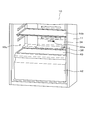
- FIG. 2 is a perspective view of the refrigerator 10 in a state in which the refrigerator compartment door 16a is opened, as viewed from an oblique front.
- 3 and 5 are cross-sectional views showing the main part of the configuration of the lower part of the refrigerator 10.
- 4 and 6 are perspective views of the flow path upper surface member 34 as seen from the rear and the lower side of the refrigerator 10.
- the refrigerator 10 includes a refrigerator main body 11 including a heat insulating box body filled with, for example, a foam heat insulating material between an outer box that forms an outer shell and an inner box that forms a storage space. .
- a storage space formed inside the refrigerator main body 11 is partitioned into an upper refrigerated storage chamber 14 and a lower refrigerated storage chamber 16 by a partition wall 12.
- the partition wall 12 thermally partitions the storage space formed inside the refrigerator main body 11, the upper surface of the partition wall 12 constitutes the bottom surface 12 a of the refrigerated storage chamber 14, and the lower surface of the partition wall 12 is refrigerated storage.
- the ceiling surface 12b of the chamber 16 is configured.
- the front opening of the freezer compartment 14 is configured to be openable and closable by a freezer compartment door 14a disposed in front of the refrigerator 10.
- the front opening of the refrigerated storage room 16 is configured to be openable and closable by a refrigerated room door 16 a disposed on the front surface of the refrigerator 10.
- the freezer storage chamber 14 is a space cooled to a freezing temperature of ⁇ 18 ° C. or lower, for example.
- the inside of the freezer compartment 14 is divided up and down by a mounting shelf 14b.
- a cooler chamber 20 that houses a cooler 18 is provided at the back of the frozen storage chamber 14.
- a cooler 18 and a blower fan 24 are accommodated in the cooler chamber 20, a cooler 18 and a blower fan 24 are accommodated.
- a rear plate 26 that forms a cooler chamber 20 with the refrigerator main body 11 is provided at the rear portion of the frozen storage chamber 14.
- the back plate 26 constitutes the back surface of the frozen storage chamber 14.
- the cooler cover 19 is disposed on the front side of the cooler 18 and faces the back plate 26.
- a refrigeration duct 38 is formed between the cooler cover 19 and the back plate 26 of the refrigeration storage chamber 14.
- the refrigeration duct 38 is connected to a refrigeration duct 30 provided on the back surface of the refrigerated storage chamber 16.
- the air blown out from the blower fan 24, which is a wind power generation means, is configured to flow from the refrigeration duct 38 into the refrigeration duct 30 provided on the back surface of the refrigeration storage chamber 16.
- the cooler 18 provided in the cooler chamber 20 constitutes a refrigeration cycle together with a compressor 44 provided at the lower part of the refrigerator 10 and a condenser, a capillary tube (not shown) and the like.
- the compressor 44 is disposed in a machine room 46 provided in the lower rear portion of the refrigerator 10.
- the refrigerant discharged from the compressor 44 is introduced into the cooler 18 through a condenser and a capillary tube. Thereby, the cooler 18 cools the air in the cooler chamber 20.
- the refrigerated storage room 16 is a space cooled to a refrigeration temperature of 0 to 3 ° C., for example.
- the inside of the refrigerated storage chamber 16 is partitioned vertically by a partition plate 28 and an upper shelf 40.
- a plurality of mounting shelves 16 b are provided between the partition plate 28 and the upper shelf 40.
- Below the upper shelf 40 there is provided a drawer-type storage container 42 that is slidable in the front-rear direction with respect to the refrigerator body 11.
- the storage container 42 has an opening at the top, and the upper shelf 40 is located at the top of the storage container 42.
- the upper shelf 40 is also a cover that covers the opening at the top of the storage container 42, and is also a placement shelf or a bottom plate for stored items stored in the storage chamber 16c.
- a machine room upper plate 48 is disposed between the storage container 42 and the compressor 44.
- the refrigerator main body 11 includes a machine room upper plate part 48, and an upper plate part upper surface 49 is provided on the surface of the machine room upper plate part 48.
- An upper shelf 40 is disposed on the lower surface of the lowermost storage chamber 16 c of the refrigerated storage chamber 16.
- a flow path upper surface member 34 is disposed on the upper side of the storage container 42 and on the inner side of the storage chamber 16c.
- the lower duct 31 is configured by the upper plate portion upper surface 49 of the machine chamber upper plate portion 48 positioned at the upper portion of the machine chamber 46 and the flow path upper surface member 34.
- a flow path switching mechanism 32 is provided above the lower duct 31.
- the flow path switching mechanism 32 includes an operation lever 32a serving as a flow path switching means and a closing plate 32b provided integrally with the operation lever 32a.
- the flow path switching mechanism 32 includes a first slit 58 and a second slit 60 that are configured to be closed by the closing plate 32b.
- the flow path switching mechanism 32 is configured such that the closing plate 32b can be operated by moving the operation lever 32a so as to slide left and right.
- the flow path switching mechanism 32 is configured to switch between opening and closing of the first slit 58 and the second slit 60 and to switch the path of the cold air passing through the lower duct 31, that is, the first flow path 54 and the second flow path 56. Yes.
- the operation lever 32a is disposed above the storage container 42 and in front of the lower duct 31 so as to protrude forward from the back wall of the storage chamber 16c.
- An operation display indicating the operation direction of the operation lever 32a and the level of humidity adjustment may be provided around the operation lever 32a by printing or sticker.
- the flow path upper surface member 34 includes a first vertical portion 34a extending in the vertical direction behind the refrigerator 10, and includes a horizontal portion 36 extending substantially horizontally from the first vertical portion 34a toward the front.
- the flow path upper surface member 34 further includes a second vertical portion 34b extending downward in the vertical direction on the front side.
- the upper shelf 40 and the horizontal portion 36 are disposed at substantially the same height.
- the horizontal portion 36 of the flow path upper surface member 34 is configured to be continuous with the upper shelf 40 on the back side of the storage chamber 16c.
- the flow path upper surface member 34 has a shape having a curvature so that the first vertical portion 34a, the horizontal portion 36, and the second vertical portion 34b are continuously connected.
- the channel upper surface member 34 includes a first side wall 52a and a second side wall 52b that extend in the vertical direction on the left and right sides of the back surface portion and are configured to follow the shape of the back surface of the channel upper surface member 34.
- a partition wall 52c extending in the vertical direction and configured to follow the shape of the back surface of the flow path upper surface member 34.
- the back surfaces 33 of the first side wall 52a, the second side wall 52b, and the partition wall 52c are configured to follow the shape of the upper plate upper surface 49 on the surface of the machine room upper plate 48, and the upper plate upper surface 49 It arrange
- a gap formed by the back surface of the flow path upper surface member 34, the first side wall 52a, the second side wall 52b, and the upper plate portion upper surface 49 of the machine room upper plate portion 48 constitutes the lower duct 31.
- the lower duct 31 is divided into a first channel 54 and a second channel 56 on the left and right by a partition wall 52c.
- the lower duct 31 is divided into a first flow path 54 and a second flow path 56.
- the 1st flow path 54 and the 2nd flow path 56 are arrange
- the position of the closing plate 32b is changed by operating the operation lever 32a left and right.
- 3 and 4 show a state where the second slit 60 on the left side as viewed from the rear of the refrigerator 10 is closed by the closing plate 32b, and the first slit 58 on the right side as viewed from the rear of the refrigerator 10 is opened. Yes.
- the first flow path 54 constituted by the first side wall 52a and the partition wall 52c is formed so as to communicate with the first slit 58.
- a back wall 42 a is provided on the back side of the storage container 42.
- the 1st blower outlet 61 which is a discharge port when cold air
- the first outlet 61 is located at the upper end of the back wall 42a.
- the cold air flowing into the lower duct 31 from the refrigeration duct 30 is introduced into the first flow path 54 through the first slit 58 in the open state.
- the cool air introduced into the first flow path 54 flows downward along the shape of the flow path upper surface member 34, passes through the first outlet 61 provided at the lower part of the flow path upper surface member 34, and It is introduced into the gap between the back of the outer periphery, that is, the back wall 42 a on the back side of the storage container 42, and the inner box wall 50 of the refrigerator body 11.
- cold air is directly introduced into the outer periphery of the storage container 42, and the inside of the storage container 42 is indirectly cooled by cooling the outer periphery of the storage container 42.
- the cold air passes through the path 64 from the outer periphery of the storage container 42 to the lower path 64, the path 66 from the front side to the upper direction, and the like, and is introduced into the storage chamber 16c after cooling the storage container 42 from the outside.
- FIG 5 and 6 show a state in which the first slit 58 on the right side as viewed from the rear of the refrigerator 10 is closed by the closing plate 32b and the second slit 60 on the left side is opened.
- the second flow path 56 is configured by the second side wall 52b and the partition wall 52c so as to communicate with the second slit 60.
- the second side wall 52b and the partition wall 52c are connected to the lower wall part 52d at the lower end, and are configured to draw a U shape by the second side wall 52b, the partition wall 52c, and the lower wall part 52d. .
- the second flow path 56 passes through the second slit 60 from the direction of the refrigeration duct 30, wraps around in the forward direction, and is directed in the forward direction from the second outlet 62.
- a back wall 42a is provided at the back side of the storage container 42, and a rear edge 42b is provided at the rear end of the storage container 42 and at the top of the back wall 42a.
- the position of the second outlet 62 is provided behind the rear edge 42b.
- the second outlet 62 which is a discharge outlet when the cold air passes through the second flow path 56, is disposed between the upper shelf 40 and the back wall 42a.
- the second outlet 62 is located at the upper end of the back wall 42a.
- the refrigerator 10 includes a channel upper surface member 34, and the channel upper surface member 34 includes a channel switching mechanism 32.
- the flow path switching mechanism 32 includes an operation lever 32a and a closing plate 32b that is configured integrally with the operation lever 32a and that can switch between opening and closing of the first slit 58 and the second slit 60.
- the closing plate 32b is formed so as to protrude from the rear wall of the storage chamber 16c to the near side, and the operation lever 32a arranged to be operable by the user is slid left and right to close the first slit 58, and the second slit 60 is configured to be switchable.
- the first flow path 54 that is a part of the lower duct 31 that is the path of the cold air and passes through the first slit 58 introduces the cold air to the outer periphery of the storage container 42.
- the second flow path 56 that is a part of the lower duct 31 that is the path of the cold air and passes through the second slit 60 introduces the cold air directly into the storage container 42.
- the first slit 58 is closed and the second slit 60 is opened by sliding the operation lever 32a. Switch to the state to be activated. Then, by blowing cold air directly into the storage container 42, the temperature difference between the inside and outside of the storage container 42 is balanced, and condensation can be eliminated. Thereby, it becomes possible to suppress damaging, for example, vegetables stored in the storage container 42.
- the cool air is directly introduced into the storage container 42 from the lower duct 31, that is, the first flow path 54, and the cool air is directly applied to the outer periphery of the storage container 42 from the lower duct 31, that is, the second flow path 56.
- the state to be introduced can be switched by the user. Thereby, temperature adjustment and humidity adjustment in the storage container 42 are enabled, and furthermore, it is possible to remove condensation generated on the outer periphery of the storage container 42 or to suppress the occurrence of condensation.
- the upper shelf 40 which becomes the bottom part of the storage chamber 16c is provided in the upper part of the storage container 42. As shown in FIG.
- the upper shelf 40 is also a cover that covers the upper entrance of the storage container 42.
- a second outlet 62 which is an outlet from the lower duct 31 of the second flow path 56, is disposed between the upper shelf 40 and the back wall 42 a of the storage container 42. Since the storage container 42 is covered with the upper shelf 40, when the cold air is passed to the outer periphery of the storage container 42, the humidity in the storage container 42 can be kept high. In addition, when cold air is introduced into the storage container 42, the cold air easily hits the upper shelf 40, and when condensation is attached to the upper shelf 40, it can be efficiently removed.
- a horizontal portion 36 of a flow path upper surface member 34 configured to be continuous with the upper shelf 40 is provided on the back side of the storage chamber 16c.
Abstract
実施形態に係る冷蔵庫は、開口を備える貯蔵容器と、冷却器にて生成された冷気を前記貯蔵容器及び前記貯蔵容器の外周に直接に導入するダクトと、前記ダクトに備えられ、前記貯蔵容器の外周に冷気を導入する第1の流路と、前記ダクトに備えられ、前記貯蔵容器の前記開口に冷気を導入する第2の流路と、前記第1の流路と前記第2の流路との切替を行う流路切替手段を備える。
Description
本発明の実施形態は、冷蔵庫に関する。
例えば、冷蔵対象物である野菜を収納することを主目的とした容器を備える冷蔵庫において、当該容器内を冷却するために直接冷気を吹き入れた場合、容器内の湿度が下がり、野菜が乾燥するため野菜の鮮度が落ちてしまうという問題があった。
また、冷気を容器内に吹き入れない場合には、容器内の湿度は上がるが、容器内外の湿度差で容器外周に結露が発生しやすくなり、容器の天井棚板に付着した水滴が野菜等に垂れ落ちてしまうことで野菜を傷めてしまうという問題があった。
そこで、容器内の温度や湿度を調整可能とし、冷蔵対象物を傷めることを抑制しつつ、当該容器内を効果的に冷却可能な冷蔵庫を提供する。
実施形態に係る冷蔵庫は、開口を備える貯蔵容器と、冷却器にて生成された冷気を前記貯蔵容器及び前記貯蔵容器の外周に直接に導入するダクトと、前記ダクトに備えられ、前記貯蔵容器の外周に冷気を導入する第1の流路と、前記ダクトに備えられ、前記貯蔵容器の前記開口に冷気を導入する第2の流路と、前記第1の流路と前記第2の流路との切替を行う流路切替手段を備える。
以下、実施形態による冷蔵庫を、図面を参照しながら説明する。なお、各実施形態において実質的に同一の構成部位には同一の符号を付し、説明を省略する。
実施形態について図1から図6を参照して説明する。以下の説明において、冷蔵庫10の冷凍室扉14a及び16a側を前側、前面側とし、その反対方向を後側、背面側、又は奥側とする。図中の矢印は冷気が流れる経路を模式的に示すものである。
実施形態について図1から図6を参照して説明する。以下の説明において、冷蔵庫10の冷凍室扉14a及び16a側を前側、前面側とし、その反対方向を後側、背面側、又は奥側とする。図中の矢印は冷気が流れる経路を模式的に示すものである。
図1は実施形態に係る冷蔵庫1の概略構成を示す側面縦断面図である。図2は冷蔵室扉16aを開けた状態の冷蔵庫10を斜め正面から見た斜視図である。図3及び図5は、冷蔵庫10の下部の構成を示す要部断面図である。図4及び図6は、流路上面部材34を冷蔵庫10の後方やや下側から見た斜視図である。
図1に示すように、実施形態に係る冷蔵庫10は、外郭を形成する外箱と貯蔵空間を形成する内箱との間に例えば発泡断熱材を充填した断熱箱体からなる冷蔵庫本体11を備える。冷蔵庫本体11の内部に形成される貯蔵空間は、仕切壁12によって上方の冷凍貯蔵室14と下方の冷蔵貯蔵室16とに区画されている。
仕切壁12は、冷蔵庫本体11の内部に形成される貯蔵空間を上下に断熱区画しており、仕切壁12の上面が冷凍貯蔵室14の底面12aを構成し、仕切壁12の下面が冷蔵貯蔵室16の天井面12bを構成している。
冷凍貯蔵室14の前面開口部は、冷蔵庫10前面に配置された冷凍室扉14aによって開閉可能に構成されている。冷蔵貯蔵室16の前面開口部は、冷蔵庫10前面に配置された冷蔵室扉16aによって開閉可能に構成されている。
冷凍貯蔵室14は、例えば-18℃以下の冷凍温度に冷却される空間である。冷凍貯蔵室14内は、載置棚14bによって上下に区画されている。冷凍貯蔵室14の背部には、冷却器18を収納する冷却器室20が設けられている。
冷却器室20の内部には、冷却器18と送風ファン24とが収納されている。冷凍貯蔵室14の後部には、冷蔵庫本体11との間で冷却器室20を形成する背面板26が設けられている。背面版26は冷凍貯蔵室14の背面を構成している。冷却器カバー19は冷却器18の前面側に配置され、背面板26に対向している。
冷却器カバー19と、冷凍貯蔵室14の背面板26の間には冷凍ダクト38が形成されている。冷凍ダクト38は冷蔵貯蔵室16の背面に設けられた冷蔵ダクト30に接続されている。風力発生手段である送風ファン24から吹出した空気は、冷凍ダクト38から、冷蔵貯蔵室16の背面に設けられた冷蔵ダクト30に流れ込むように構成されている。
冷却器室20に設けられた冷却器18は、冷蔵庫10の下部に設けられた圧縮機44、及び、不図示の凝縮器やキャピラリーチューブ等と共に冷凍サイクルを構成している。圧縮機44は冷蔵庫10後方下部に設けられた機械室46内に配置されている。圧縮機44から吐出される冷媒が凝縮器及びキャピラリーチューブを介して冷却器18に導入される。これにより、冷却器18は冷却器室20内の空気を冷却する。
冷蔵貯蔵室16は、例えば、0~3℃の冷蔵温度に冷却される空間である。冷蔵貯蔵室16の内部は、仕切板28及び上棚40によって上下に区画されている。図1に例示する冷蔵庫10では、仕切板28及び上棚40の間には複数段の載置棚16bが設けられている。上棚40の下方には、冷蔵庫本体11に対して前後方向に摺動可能に設けられた引き出し式の貯蔵容器42が設けられている。貯蔵容器42は上部に開口を有しており、上棚40は貯蔵容器42の上部に位置している。上棚40は、貯蔵容器42上部の開口を覆う覆い部でもあり、貯蔵室16cに貯蔵される貯蔵物の載置棚もしくは底板でもある。
貯蔵容器42と圧縮機44との間には機械室上板部48が配置されている。機械室46の上部において、冷蔵庫本体11は機械室上板部48を備えており、機械室上板部48の表面に上板部上面49を備える。冷蔵貯蔵室16の最下部の貯蔵室16cの下面には上棚40が配置される。
図2から図6に示すように、貯蔵容器42の上側であって貯蔵室16cの奥側には流路上面部材34が配置されている。機械室46の上部に位置する機械室上板部48の上板部上面49と、流路上面部材34により、下部ダクト31が構成されている。下部ダクト31上方には、流路切替機構32が設けられている。流路切替機構32は、流路切替手段たる操作レバー32a、及び操作レバー32aに一体的に備えられた閉塞板32bを備えている。流路切替機構32は、閉塞板32bにより閉塞可能に構成される第1スリット58及び第2スリット60を備えている。流路切替機構32は、操作レバー32aを左右にスライドするように動かすことによって閉塞板32bを操作することができるように構成されている。流路切替機構32は、第1スリット58と第2スリット60の開閉を切り替え、下部ダクト31内を通過する冷風の経路すなわち第1流路54と第2流路56を切り替え可能に構成されている。操作レバー32aは、貯蔵容器42の上方であって、下部ダクト31の前方に、貯蔵室16cの奥壁から前方に突出するようにして配置されている。なお、操作レバー32a周囲には操作レバー32aの動作方向と湿度調整の高低を示す操作表示が、印刷やシールによって施されていてもよい。
流路上面部材34は、冷蔵庫10後方に垂直方向に延伸する第1垂直部34aを有し、第1垂直部34aから前方に向かって略水平に延伸する水平部36を備えている。流路上面部材34は、更に前側に垂直方向下側に延伸する第2垂直部34bを備えている。上棚40と水平部36は、略同じ高さに配置されている。流路上面部材34の水平部36は、貯蔵室16cの奥側に上棚40に連続する形状となるように構成されている。
流路上面部材34は、これら第1垂直部34a、水平部36、及び第2垂直部34bが連続して接続するように曲率を有した形状を備えている。
流路上面部材34は、背面部の左右に、上下方向に延伸し、流路上面部材34背面の形状に沿うように構成された第1側面壁52a及び第2側面壁52bを備えている。第1側面壁52aと第2側面壁52bの中央には、上下方向に延伸し、流路上面部材34背面の形状に沿うように構成された仕切壁52cを備えている。第1側面壁52a、第2側面壁52b、及び仕切壁52cの背面33は、機械室上板部48表面の上板部上面49の形状に沿うように構成されており、上板部上面49表面に密着するように配置されている。流路上面部材34の裏面、第1側面壁52a、第2側面壁52b、及び機械室上板部48の上板部上面49により形成された隙間は下部ダクト31を構成している。下部ダクト31は仕切壁52cにより、左右に、第1流路54及び第2流路56に分けられている。下部ダクト31は第1流路54と第2流路56に分断される。第1流路54と第2流路56は、左右方向に隣接して配置されている。
流路上面部材34は、背面部の左右に、上下方向に延伸し、流路上面部材34背面の形状に沿うように構成された第1側面壁52a及び第2側面壁52bを備えている。第1側面壁52aと第2側面壁52bの中央には、上下方向に延伸し、流路上面部材34背面の形状に沿うように構成された仕切壁52cを備えている。第1側面壁52a、第2側面壁52b、及び仕切壁52cの背面33は、機械室上板部48表面の上板部上面49の形状に沿うように構成されており、上板部上面49表面に密着するように配置されている。流路上面部材34の裏面、第1側面壁52a、第2側面壁52b、及び機械室上板部48の上板部上面49により形成された隙間は下部ダクト31を構成している。下部ダクト31は仕切壁52cにより、左右に、第1流路54及び第2流路56に分けられている。下部ダクト31は第1流路54と第2流路56に分断される。第1流路54と第2流路56は、左右方向に隣接して配置されている。
図3及び図4に示すように、流路切替機構32において、操作レバー32aを左右に操作することによって閉塞板32bの位置が変更される。図3及び図4は、冷蔵庫10の後方から見て左側の第2スリット60が閉塞板32bにより閉塞され、冷蔵庫10の後方から見て右側の第1スリット58が開放されている状態を示している。この場合、第1スリット58に連通するように、第1側面壁52aと仕切壁52cで構成された第1流路54が形成される。貯蔵容器42の奥側には背壁42aが設けられている。冷気が第1流路54を通過する場合の吐出口である第1吹出し口61は、背壁42aと、背壁42a後方の背面部50の間に配置されている。また、第1吹出し口61は背壁42a上端に位置する。
冷蔵ダクト30から下部ダクト31に流れ込んだ冷気は、開放状態の第1スリット58を通り、第1流路54に導入される。第1流路54に導入された冷気は、流路上面部材34の形状に沿って下方向に流れ、流路上面部材34下部に設けられた第1吹出し口61を通過し、貯蔵容器42の外周後方、すなわち貯蔵容器42の奥側の背壁42aと、冷蔵庫本体11の内箱壁50との間の隙間に導入される。これにより、冷気が貯蔵容器42の外周に直接導入され、貯蔵容器42内は、貯蔵容器42の外周が冷却されることにより、間接的に冷却される。
冷風は、図3に示すように、貯蔵容器42の外周から下側の経路64や、前側から上方向に向かう経路66等を通り、貯蔵容器42を外側から冷却した後に貯蔵室16cに導入される。
次に、図5及び図6は、冷蔵庫10の後方から見て右側の第1スリット58が閉塞板32bにより閉塞され、左側の第2スリット60が開放されている状態を示している。この場合、第2スリット60に連通するように、第2側面壁52bと仕切壁52cによって第2流路56が構成される。
第2側面壁52bと仕切壁52cは、下端において下壁部52dに接続されており、第2側面壁52b、仕切壁52c及び下壁部52dにより、Uの字を描くように構成されている。第2流路56は、冷蔵ダクト30方向から、第2スリット60を通過し、前方向に回り込んで第2吹出し口62から前方向に指向している。
貯蔵容器42の奥側には背壁42aが設けられており、貯蔵容器42の後端であって背壁42a上部には後縁42bが設けられている。第2吹出し口62の位置は、後縁42bよりも後方に設けられている。これにより、第2吹出し口62からの結露による水垂れ落ちが、貯蔵容器42内に入らないようにすることができる。
冷気が第2流路56を通過する場合の吐出口である第2吹出し口62は、上棚40と背壁42aとの間に配置されている。また、第2吹出し口62は背壁42a上端に位置する。これにより、冷蔵ダクト30から導入された冷気は、第2スリット60を通過して下部ダクト31の第2流路56を通過し、下壁部52dにより下方向の行く手を阻まれ、前方に誘導されて吹出し口62を通り抜け、貯蔵容器42内に直接導入される。すなわち、冷風は下部ダクト31から直接に貯蔵容器42内に導入される。
実施形態の冷蔵庫10によれば以下の効果を奏する。
冷蔵庫10は流路上面部材34を備えており、流路上面部材34は流路切替機構32を備えている。流路切替機構32は、操作レバー32a及びこれに一体的に構成され、第1スリット58及び第2スリット60の開閉を切り替え可能に構成された閉塞板32bを備えている。閉塞板32bは、貯蔵室16c奥壁から手前側に突出形成され、ユーザにより操作可能に配置された操作レバー32aを左右にスライドさせることにより、第1スリット58を閉塞した状態と、第2スリット60を閉塞した状態とを切り替え可能に構成されている。冷気の経路である下部ダクト31の一部であって第1スリット58を通過する第1流路54は、冷気を貯蔵容器42の外周に導入する。冷気の経路である下部ダクト31の一部であって第2スリット60を通過する第2流路56は、冷気を直接、貯蔵容器42の内部に導入する。この構成により、冷気を第1スリット58及び第1吹出し口61を通過させて貯蔵容器42の外周に導入した場合には、貯蔵容器42内をその外周から冷却することで貯蔵容器42内の湿度を高く保つことができ、外周に結露が発生する場合には、結露の発生を抑制又は除去することができる。
冷蔵庫10は流路上面部材34を備えており、流路上面部材34は流路切替機構32を備えている。流路切替機構32は、操作レバー32a及びこれに一体的に構成され、第1スリット58及び第2スリット60の開閉を切り替え可能に構成された閉塞板32bを備えている。閉塞板32bは、貯蔵室16c奥壁から手前側に突出形成され、ユーザにより操作可能に配置された操作レバー32aを左右にスライドさせることにより、第1スリット58を閉塞した状態と、第2スリット60を閉塞した状態とを切り替え可能に構成されている。冷気の経路である下部ダクト31の一部であって第1スリット58を通過する第1流路54は、冷気を貯蔵容器42の外周に導入する。冷気の経路である下部ダクト31の一部であって第2スリット60を通過する第2流路56は、冷気を直接、貯蔵容器42の内部に導入する。この構成により、冷気を第1スリット58及び第1吹出し口61を通過させて貯蔵容器42の外周に導入した場合には、貯蔵容器42内をその外周から冷却することで貯蔵容器42内の湿度を高く保つことができ、外周に結露が発生する場合には、結露の発生を抑制又は除去することができる。
また、高湿時において貯蔵容器42の上面に位置する棚、すなわち上棚40の結露が発生する場合は、操作レバー32aをスライドさせることにより、第1スリット58を閉塞させ、第2スリット60を開放させる状態に切り替える。そうすると、貯蔵容器42内に直接冷気を吹き込むことで貯蔵容器42内部と外部の温度差が均衡となり、結露を解消することができる。これにより、貯蔵容器42内に格納された例えば野菜を傷めることを抑制することが可能となる。
また、上記のように、下部ダクト31すなわち第1流路54から、貯蔵容器42に直接冷気を導入する状態と、下部ダクト31すなわち第2流路56から、貯蔵容器42の外周に直接冷気を導入する状態を、ユーザにより切り替え可能とする。これにより、貯蔵容器42内の温度調節や湿度調整を可能とし、さらに、貯蔵容器42外周に発生した結露の除去または結露発生の抑制を図ることができる。
貯蔵容器42の上部に貯蔵室16cの底部となる上棚40が設けられている。また、上棚40は貯蔵容器42の上部入り口を覆う覆い部でもある。第2流路56の下部ダクト31からの吐出口である第2吹出し口62は、上棚40と貯蔵容器42の背壁42aとの間に配置されている。貯蔵容器42が上棚40により蓋をされているため、冷気を貯蔵容器42外周に通じた場合には、貯蔵容器42内の湿度を高く保持可能となる。また、貯蔵容器42内に冷気を導入する場合には、冷気が上棚40に当たりやすくなり、上棚40に結露が付着している場合には、これを効率的に除去することが可能となる。
また、貯蔵室16cの奥側には上棚40に連続する形状となるように構成された流路上面部材34の水平部36が設けられている。これにより、貯蔵室16c内の貯蔵空間を大きくすることができ、貯蔵能力を向上させることができる。
本発明のいくつかの実施形態を説明したが、これらの実施形態は、例として提示したものであり、発明の範囲を限定することは意図していない。これら新規な実施形態は、その他の様々な形態で実施されることが可能であり、発明の要旨を逸脱しない範囲で、種々の省略、置き換え、変更を行うことができる。これら実施形態やその変形は、発明の範囲や要旨に含まれるとともに、特許請求の範囲に記載された発明とその均等の範囲に含まれる。
Claims (9)
- 開口を備える貯蔵容器と、
冷却器にて生成された冷気を前記貯蔵容器及び前記貯蔵容器の外周に直接に導入するダクトと、
前記ダクトに備えられ、前記貯蔵容器の外周に冷気を導入する第1の流路と、
前記ダクトに備えられ、前記貯蔵容器の前記開口に冷気を導入する第2の流路と、
前記第1の流路と前記第2の流路との切替を行う流路切替手段を備える冷蔵庫。 - 前記貯蔵容器の前記開口に覆い部を備える請求項1に記載の冷蔵庫。
- 前記ダクトの吹出し口は、前記覆い部と前記貯蔵容器の背壁との間に配置されている請求項2に記載の冷蔵庫。
- 前記貯蔵容器の上部に設けられた貯蔵室の底板を備えており、
前記ダクトの吹出し口は、前記背壁と、前記底板との間に配置されている請求項1に記載の冷蔵庫。 - 前記第1の流路と、前記第2の流路は、左右方向に隣接して配置されている請求項1から4のいずれか一項に記載の冷蔵庫。
- 前記流路切替手段は、前記貯蔵容器の上方であって、前記ダクトの前方に配置され、左右にスライドさせることにより、前記第1の流路と第2の流路を切替可能に構成される請求項1から5のいずれか一項に記載の冷蔵庫。
- 前記覆い部は前記貯蔵容器の上部に設けられた貯蔵室の底板であり、
前記ダクトは後方から前方に向けて配置されるダクト上面部材を備え、
前記ダクト上面部材は前記底板に連続する形状となるように構成されている請求項2又は3に記載の冷蔵庫。 - さらに、内部に圧縮機を配し上部に機械室上板を有する機械室を備え、
前記ダクト上面部材は前記底板に連続する形状となる水平部を備え、
前記覆い部は前記水平部と略同じ高さに配置されており、
前記第1の流路及び前記第2の流路は、前記ダクト上面部材と前記機械室上板とにより構成されている請求項2、3、又は7のいずれか一項に記載の冷蔵庫。 - 前記ダクトの吹出し口は、前記貯蔵容器の後縁よりも後方に配置されている請求項1から8のいずれか一項に記載の冷蔵庫。
Priority Applications (1)
| Application Number | Priority Date | Filing Date | Title |
|---|---|---|---|
| CN201680076731.1A CN108474609A (zh) | 2016-01-12 | 2016-08-05 | 冰箱 |
Applications Claiming Priority (2)
| Application Number | Priority Date | Filing Date | Title |
|---|---|---|---|
| JP2016-003508 | 2016-01-12 | ||
| JP2016003508A JP6889522B2 (ja) | 2016-01-12 | 2016-01-12 | 冷蔵庫 |
Publications (1)
| Publication Number | Publication Date |
|---|---|
| WO2017122380A1 true WO2017122380A1 (ja) | 2017-07-20 |
Family
ID=59312111
Family Applications (1)
| Application Number | Title | Priority Date | Filing Date |
|---|---|---|---|
| PCT/JP2016/073127 WO2017122380A1 (ja) | 2016-01-12 | 2016-08-05 | 冷蔵庫 |
Country Status (3)
| Country | Link |
|---|---|
| JP (1) | JP6889522B2 (ja) |
| CN (1) | CN108474609A (ja) |
| WO (1) | WO2017122380A1 (ja) |
Families Citing this family (3)
| Publication number | Priority date | Publication date | Assignee | Title |
|---|---|---|---|---|
| JP6578051B1 (ja) * | 2018-11-20 | 2019-09-18 | 日立グローバルライフソリューションズ株式会社 | 冷蔵庫 |
| CN111412721B (zh) * | 2020-03-30 | 2021-05-25 | 珠海格力电器股份有限公司 | 冰箱 |
| CN114543411B (zh) * | 2020-11-26 | 2024-03-19 | 青岛海尔电冰箱有限公司 | 冰箱的控制方法及冰箱 |
Citations (5)
| Publication number | Priority date | Publication date | Assignee | Title |
|---|---|---|---|---|
| JPS5825993U (ja) * | 1981-08-17 | 1983-02-18 | 三菱電機株式会社 | 冷蔵庫 |
| JPH0191871U (ja) * | 1987-12-10 | 1989-06-16 | ||
| JPH01310283A (ja) * | 1988-06-08 | 1989-12-14 | Sanyo Electric Co Ltd | 冷蔵庫 |
| JPH05133670A (ja) * | 1991-11-12 | 1993-05-28 | Sanyo Electric Co Ltd | 冷蔵庫 |
| JP2006275297A (ja) * | 2005-03-25 | 2006-10-12 | Toshiba Corp | 冷蔵庫 |
Family Cites Families (7)
| Publication number | Priority date | Publication date | Assignee | Title |
|---|---|---|---|---|
| KR100414289B1 (ko) * | 2001-11-23 | 2004-01-07 | 주식회사 엘지이아이 | 냉장고의 냉기순환구조 |
| KR100524785B1 (ko) * | 2002-10-23 | 2005-10-31 | 엘지전자 주식회사 | 냉장고의 야채실 최적상태 보존 장치 |
| US20090199587A1 (en) * | 2005-04-04 | 2009-08-13 | Fisher & Paykel Appliances Limited | Humidity control lid |
| JP4595972B2 (ja) * | 2007-07-30 | 2010-12-08 | 三菱電機株式会社 | 冷蔵庫 |
| PL2324306T3 (pl) * | 2008-09-09 | 2017-05-31 | Arçelik Anonim Sirketi | Urządzenie chłodzące |
| CN102901302B (zh) * | 2011-07-29 | 2015-07-08 | 株式会社东芝 | 冰箱 |
| JP5787837B2 (ja) * | 2012-07-23 | 2015-09-30 | 三菱電機株式会社 | 冷蔵庫 |
-
2016
- 2016-01-12 JP JP2016003508A patent/JP6889522B2/ja active Active
- 2016-08-05 WO PCT/JP2016/073127 patent/WO2017122380A1/ja active Application Filing
- 2016-08-05 CN CN201680076731.1A patent/CN108474609A/zh active Pending
Patent Citations (5)
| Publication number | Priority date | Publication date | Assignee | Title |
|---|---|---|---|---|
| JPS5825993U (ja) * | 1981-08-17 | 1983-02-18 | 三菱電機株式会社 | 冷蔵庫 |
| JPH0191871U (ja) * | 1987-12-10 | 1989-06-16 | ||
| JPH01310283A (ja) * | 1988-06-08 | 1989-12-14 | Sanyo Electric Co Ltd | 冷蔵庫 |
| JPH05133670A (ja) * | 1991-11-12 | 1993-05-28 | Sanyo Electric Co Ltd | 冷蔵庫 |
| JP2006275297A (ja) * | 2005-03-25 | 2006-10-12 | Toshiba Corp | 冷蔵庫 |
Also Published As
| Publication number | Publication date |
|---|---|
| JP6889522B2 (ja) | 2021-06-18 |
| CN108474609A (zh) | 2018-08-31 |
| JP2017125629A (ja) | 2017-07-20 |
Similar Documents
| Publication | Publication Date | Title |
|---|---|---|
| US10634418B2 (en) | Refrigerator | |
| EP3217126B1 (en) | Refrigerator | |
| JP6709347B2 (ja) | 冷蔵庫 | |
| WO2017122380A1 (ja) | 冷蔵庫 | |
| JP6603054B2 (ja) | 冷蔵庫 | |
| JP2015178943A (ja) | 冷蔵庫 | |
| JP4641967B2 (ja) | 貯蔵庫 | |
| JP2014081105A (ja) | 冷蔵庫 | |
| JP7401898B2 (ja) | 冷蔵庫 | |
| JP6622980B2 (ja) | 冷蔵庫 | |
| JP2006250465A (ja) | 冷蔵庫 | |
| JP6592274B2 (ja) | 冷蔵庫 | |
| JP7266624B2 (ja) | 冷蔵庫 | |
| JP6359297B2 (ja) | 冷蔵庫 | |
| JP6302326B2 (ja) | 冷蔵庫 | |
| JP6919008B2 (ja) | 冷蔵庫 | |
| JP6783380B2 (ja) | 冷蔵庫 | |
| JP4991609B2 (ja) | 冷蔵庫 | |
| JP6726488B2 (ja) | 冷蔵庫 | |
| JP2007271243A (ja) | 貯蔵庫 | |
| JP2018077036A (ja) | ダンパ装置およびそれを用いた冷蔵庫 | |
| JP7029158B2 (ja) | 冷蔵庫 | |
| JP6813262B2 (ja) | 冷蔵庫 | |
| JP6489767B2 (ja) | 冷蔵庫 | |
| JP2014156947A (ja) | 冷蔵庫 |
Legal Events
| Date | Code | Title | Description |
|---|---|---|---|
| 121 | Ep: the epo has been informed by wipo that ep was designated in this application |
Ref document number: 16884983 Country of ref document: EP Kind code of ref document: A1 |
|
| NENP | Non-entry into the national phase |
Ref country code: DE |
|
| 122 | Ep: pct application non-entry in european phase |
Ref document number: 16884983 Country of ref document: EP Kind code of ref document: A1 |