WO2017122374A1 - 小型電動車両 - Google Patents
小型電動車両 Download PDFInfo
- Publication number
- WO2017122374A1 WO2017122374A1 PCT/JP2016/069237 JP2016069237W WO2017122374A1 WO 2017122374 A1 WO2017122374 A1 WO 2017122374A1 JP 2016069237 W JP2016069237 W JP 2016069237W WO 2017122374 A1 WO2017122374 A1 WO 2017122374A1
- Authority
- WO
- WIPO (PCT)
- Prior art keywords
- brake
- self
- lever
- brake lever
- electric vehicle
- Prior art date
- Legal status (The legal status is an assumption and is not a legal conclusion. Google has not performed a legal analysis and makes no representation as to the accuracy of the status listed.)
- Ceased
Links
Images







Classifications
-
- B—PERFORMING OPERATIONS; TRANSPORTING
- B60—VEHICLES IN GENERAL
- B60L—PROPULSION OF ELECTRICALLY-PROPELLED VEHICLES; SUPPLYING ELECTRIC POWER FOR AUXILIARY EQUIPMENT OF ELECTRICALLY-PROPELLED VEHICLES; ELECTRODYNAMIC BRAKE SYSTEMS FOR VEHICLES IN GENERAL; MAGNETIC SUSPENSION OR LEVITATION FOR VEHICLES; MONITORING OPERATING VARIABLES OF ELECTRICALLY-PROPELLED VEHICLES; ELECTRIC SAFETY DEVICES FOR ELECTRICALLY-PROPELLED VEHICLES
- B60L15/00—Methods, circuits, or devices for controlling the traction-motor speed of electrically-propelled vehicles
- B60L15/20—Methods, circuits, or devices for controlling the traction-motor speed of electrically-propelled vehicles for control of the vehicle or its driving motor to achieve a desired performance, e.g. speed, torque, programmed variation of speed
-
- Y—GENERAL TAGGING OF NEW TECHNOLOGICAL DEVELOPMENTS; GENERAL TAGGING OF CROSS-SECTIONAL TECHNOLOGIES SPANNING OVER SEVERAL SECTIONS OF THE IPC; TECHNICAL SUBJECTS COVERED BY FORMER USPC CROSS-REFERENCE ART COLLECTIONS [XRACs] AND DIGESTS
- Y02—TECHNOLOGIES OR APPLICATIONS FOR MITIGATION OR ADAPTATION AGAINST CLIMATE CHANGE
- Y02T—CLIMATE CHANGE MITIGATION TECHNOLOGIES RELATED TO TRANSPORTATION
- Y02T10/00—Road transport of goods or passengers
- Y02T10/60—Other road transportation technologies with climate change mitigation effect
- Y02T10/72—Electric energy management in electromobility
Definitions
- the present invention relates to a small electric vehicle that can run on its own.
- a handle shaft that pivotally supports a front wheel is attached to the front end of a pipe-shaped main body, and a rear wheel is attached to the rear end of the main body via a shock absorber.
- an electric motor that transmits power to any one of the front and rear wheels is provided in the main body, and a saddle for a driver is provided in the main body, and extends in a lateral direction on the front side of the main body.
- a step bar for placing a foot is provided so as to be freely foldable.
- the two-wheeled vehicle with an auxiliary motor described in Patent Document 1 is configured so that a power switch is interlocked with a brake lever provided on a handle, and the power switch is also turned off when the brake lever is operated.
- the present invention has been made in view of the above-described points, and it is an object to provide a small electric vehicle that improves operability by executing self-running control of the vehicle by an operation using a brake lever. To do.
- the invention according to claim 1 made to solve this problem is a small electric vehicle, wherein an operation switch for instructing the start of self-running, a brake sensor for detecting a lever operation amount of a brake lever, and a vehicle are provided.
- the operation switch When the operation switch is turned on when the lever operation amount is greater than or equal to the first operation amount at the start of self-running, the self-running reservation state is established.
- the operation amount is less than the second operation amount less than one operation amount, the self-running control based on the motor drive control is started.
- the invention according to claim 2 is the small electric vehicle according to claim 1, wherein the self-propelled control is performed when the lever operation amount is less than the second operation amount. It is characterized by accelerating the running speed.
- the invention according to claim 3 is the small electric vehicle according to claim 1 or 2, wherein the self-propelled control is performed when the lever operation amount is equal to or greater than the second operation amount and less than the first operation amount.
- the self-running speed of the vehicle is reduced to a predetermined minimum speed.
- the invention according to claim 4 is the small electric vehicle according to any one of claims 1 to 3, wherein the motor is operated when the lever operation amount becomes equal to or greater than the first operation amount after the start of self-propelling.
- the stop control is performed, the self-running control is completed, and a manual braking operation by a brake lever is performed.
- the invention according to claim 5 is the small electric vehicle according to claim 2, characterized in that it includes a setting switch for switching the maximum speed.
- the invention according to claim 6 is the small electric vehicle according to any one of claims 1 to 5, wherein the first operation amount is determined by the brake caliper being operated by a manual braking operation by a brake lever. It is a lever operation amount of the brake lever to be started, and the second operation amount is a lever operation amount of the brake lever in a range where the manual braking operation by the brake lever does not affect the operation of the brake caliper.
- the invention according to claim 7 is the small electric vehicle according to any one of claims 1 to 6, comprising a seating sensor attached to the seat, and the seat based on an output signal of the seating sensor. When it is determined that the driver is seated, self-propelled control can be executed.
- the invention according to claim 8 is the small electric vehicle according to claim 7, wherein the signal indicating that the duration of one state is less than a predetermined time is invalidated in the output signal of the seating sensor.
- a prevention part is provided.
- the self-running reservation state is established when the operation switch is turned on.
- the lever operation amount of the brake lever becomes less than the second operation amount smaller than the first operation amount
- the self-running control by the motor drive control is started. Therefore, the operability can be improved by executing the vehicle self-running control by the operation using the brake lever.
- the vehicle can be started after the safety is confirmed.
- the lever operation amount of the brake lever is greater than or equal to the second operation amount and less than the first operation amount is achieved by an operation in which the brake lever is further gripped.
- the self-running speed of the vehicle is reduced to the minimum speed set. Therefore, the vehicle can be decelerated by the operation of grasping the brake lever, which has been used to date.
- the motor is controlled to stop when the lever operation amount of the brake lever becomes equal to or greater than the first operation amount by the operation of deeply grasping the brake lever after the start of self-propelled driving.
- the self-running control is completed, and a manual braking operation by the brake lever is performed. Therefore, the operation of the brake lever for stopping the vehicle can be immediately shifted from the deceleration operation in the self-running control to the manual braking operation.
- the maximum speed can be switched by using the setting switch.
- the first operation amount is a lever operation amount of the brake lever that starts the operation of the brake caliper by a manual braking operation by the brake lever
- the second operation amount is the brake operation amount. This is the lever operation amount of the brake lever in a range where the manual braking operation by the lever does not affect the operation of the brake caliper. Therefore, the brake caliper can not be operated during the self-running control, and the vehicle can be immediately shifted from the deceleration of the vehicle by the self-running control to the braking of the brake caliper manually.
- the self-running control can be executed when it is determined that the driver is seated on the seat based on the output signal of the seating sensor. Therefore, it is possible to prevent the self-running control from being executed in a state where the driver is not seated on the seat.
- the false detection prevention unit invalidates a signal indicating that the duration of one state is less than a predetermined time for the output signal of the seating sensor. Therefore, for example, when chattering occurs in the output signal of the seating sensor because the driver sitting on the seat floats for a moment or the vehicle vibrates, self-running control based on the output signal of the seating sensor Inability to execute can be prevented.
- the small electric vehicle of the present embodiment is an electric tricycle that can fold the frame, performs self-running control that can start, accelerate, decelerate, and run at a constant speed, and is mainly intended for healthy elderly people. is there.
- a part of the basic configuration may be omitted, and the dimensional ratios of the drawn parts are not necessarily accurate.
- the small electric vehicle 1 of the present embodiment includes a front frame 11, a handle shaft holder 13, and a rear frame 15.
- a handle shaft holder 13 is pivotally supported at the front end portion of the front frame 11 so as to be rotatable about the first rotation axis D1.
- a handle frame 17 is attached to the front end of the handle shaft holder 13 so as to be rotatable in a substantially horizontal direction.
- a handle 19 is fixed to the upper end portion of the handle frame 17.
- a wheel support frame 21 is fixed to the lower end portion of the handle frame 17.
- a front wheel 23 is rotatably supported on the wheel support frame 21.
- the seat post 25 is integrally connected to the rear end portion of the front frame 11.
- the upper portion of the seat post 25 has a cylindrical shape, and a seat support frame 27 is inserted into the cylindrical portion of the seat post 25 so as to be vertically movable.
- a seat 29 is fixed to the upper end portion of the seat support frame 27.
- the lock handle 31 is pivotally supported at the lower end of the seat post 25 so as to be rotatable about the second rotation axis D2.
- a lock lever 33 is provided in the lock handle 31.
- the rear frame 15 is pivotally supported at the rear end portion of the front frame 11 so as to be rotatable about the third rotation axis D3.
- a pair of rear wheels 35 are rotatably supported at the rear end portion of the rear frame 15 on both the left and right sides with respect to the front direction.
- a motor drive control unit 37 is attached to the lower surface of the rear frame 15.
- the front end portion of the first link lever 39 is pivotally supported below the rear portion of the handle shaft holder 13 so as to be rotatable about the fourth rotation axis D4.
- a front end portion of the second link lever 41 is pivotally supported at the rear end portion of the first link lever 39 so as to be rotatable about the fifth rotation axis D5.
- the rear end portion of the second link lever 41 is pivotally supported so that the front end portion of the rear frame 15 can rotate about the sixth rotation axis D6.
- a guide hole and a positioning groove 43 are provided in the rear portion of the saddle handle shaft holder 13.
- a positioning pin 45 is engaged with the guide hole and the positioning groove 43.
- the positioning pin 45 is provided at the front end of the front frame 11 and is connected to the lock lever 33 by an unillustrated inner cable.
- a pair of footrests 47 are provided at the rear part of the handle shaft holder 13 on both the left and right sides with respect to the front direction.
- the positioning pin 45 is fitted in a notch groove (hereinafter referred to as “lower notch groove”) provided below the guide hole and the positioning groove 43.
- lower notch groove a notch groove
- the lock lever 33 When switching from the unfolded state of FIG. 1 to the folded state of FIG. 2, the lock lever 33 is grasped and the lock lever 33 is pulled backward. Accordingly, the positioning pin 45 is separated from the guide hole and the lower notch groove of the positioning groove 43 via an inner cable (not shown), so that the front frame 11 is rotatable with respect to the handle shaft holder 13.
- the lock handle 31 is rotated upward away from the rear frame 15 about the second rotation axis D2.
- the claw portion 31A (see FIG. 2) of the lock handle 31 moves away from the second rotation axis D2. Therefore, the rear frame 15 connected to the second rotation axis D2 can rotate with respect to the front frame 11 with the sixth rotation axis D6 as an axis. Thereby, the small electric vehicle 1 of this embodiment can be folded.
- the lock handle 31, the handle frame 17, the handle 19 and the like are brought close to each other while the lock lever 33 is grasped, the rear weight of the front frame 11 via the seat post 25 is coupled with the weight of the small electric vehicle 1 of the present embodiment.
- the end rotates in a direction approaching the handle shaft holder 13.
- the positioning pin 45 of the front frame 11 is located in the guide hole that connects the notch groove (hereinafter referred to as “upper notch groove”) provided above the guide hole and the positioning groove 43 and the lower notch groove. ing. Therefore, the positioning pin 45 moves through the guide hole from the position of the lower notch groove of the guide hole and the positioning groove 43 to the position of the upper notch groove as the front frame 11 rotates. Further, as the front frame 11 rotates, the rear frame 15, the first link lever 39, and the second link lever 41 also rotate and move in a direction approaching the handle shaft holder 13 by the rotation shafts that are pivotally supported by each. .
- the positioning pin 45 of the front frame 11 comes into contact with the end surface of the guide hole and the positioning groove 43 on the upper notch groove side, and the rotation of the front frame 11 is suppressed.
- the lock lever 33 is released in a state where the rotation of the front frame 11 is suppressed, the positioning pin 45 of the front frame 11 is fitted into the guide hole and the upper notch groove of the positioning groove 43. Since the positioning pin 45 is held at this position by an urging force of a tension spring (not shown), the front frame 11 is locked at this folded position.
- the rear frame 15, the first link lever 39, and the second link lever 41 are also rotated in the direction closer to the handle shaft holder 13 by the rotation shafts pivotally supported on the respective frames.
- the small electric vehicle 1 of the present embodiment is in the folded state shown in FIG.
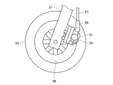
- a brake disc 49 is provided inside the front wheel 23.
- a front brake caliper 51 that constitutes a disc brake together with a brake disc 49 is fixed to the wheel support frame 21.
- the right inner cable 53 is attached to the front brake caliper 51.
- the right inner cable 53 is a drive source for the front brake caliper 51.
- the right inner cable 53 is inserted in the front first brake sensor 55, and further passes through the right outer cable 57.
- the front first brake sensor 55 is fixed to the front brake caliper 51, and one end of the right outer cable 57 is connected thereto.
- the front first brake sensor 55 detects the stroke of the right inner cable 53 and turns on when the stroke displacement of the right inner cable 53 is equal to or greater than the first predetermined distance.
- the front brake caliper 51 is activated. That is, the front brake caliper 51 operates while the front first brake sensor 55 is on.
- a brake disc 101 is provided inside the rear wheel 35.
- the rear frame 15 is provided with a rear wheel frame 15A that rotatably supports the rear wheel 35.
- a motor 85 for electrically driving the rear wheel 35 is fixed to the rear wheel frame 15A, and a rear brake caliper 103 that constitutes a disc brake together with the brake disc 101 is fixed.
- the left inner cable 105 is attached to the rear brake caliper 103.
- the left inner cable 105 is a drive source for the rear brake caliper 103.
- the left inner cable 105 is inserted into the first rear brake sensor 107 and further passes through the left outer cable 109.
- the rear first brake sensor 107 is fixed to the rear brake caliper 103, and one end of the left outer cable 109 is connected thereto.
- the rear first brake sensor 107 detects the stroke of the left inner cable 105, and turns on when the stroke displacement of the left inner cable 105 is equal to or greater than a second predetermined distance. When the stroke displacement of the left inner cable 105 is greater than or equal to the second predetermined distance, the rear brake caliper 103 is activated. That is, the rear brake caliper 103 operates while the rear first brake sensor 107 is on.
- the brake-related configuration described above may be provided in the left rear wheel 35 with respect to the front direction instead of the right rear wheel 35 with respect to the front direction.
- the handle 19 is a bar type similar to a bicycle.
- the handle 19 is provided with an ignition switch 59, a travel start switch 61, a travel enable LED 63, a speed setting switch 65, and an abnormality display LED 67.
- the ignition switch 59 is a select type switch that is used when self-running control is executed.
- the travel start switch 61 is a push button type switch used when self-running control is executed.
- the travel enable LED 63 is a display device that is turned on, blinked, or turned off when self-running control is executed.
- the speed setting switch 65 can switch the maximum speed during the self-running control to one of low speed, medium speed, and high speed. In this embodiment, the maximum speed when switched to high speed is 6 km / h.
- the abnormality display LED 67 is a display device that is turned on when an abnormality occurs when the self-running control is executed. Self-running control will be described later.
- a right brake lever 69 is attached to the handle 19 on the right side (right side with respect to the forward direction) in FIG. 5, and a left brake lever 71 is attached on the left side (left side with respect to the front direction) in FIG.
- the other end of the right outer cable 57 is connected to the right brake lever 69, and the other end of the right inner cable 53 (see FIG. 3) passing through the right outer cable 57 is attached. Yes.
- the right brake lever 69 is provided with a front second brake sensor 73.
- the front second brake sensor 73 is turned on when the right brake lever 69 moves to the position indicated by reference numeral 69B. Even when the right brake lever 69 moves from the position indicated by reference numeral 69B to the lower side in FIG. 5 (the handle 19 side), the front second brake sensor 73 is turned on. The driver can move the right brake lever 69 to the position indicated by reference numeral 69B by grasping the right brake lever 69 shallowly.
- the other end of the left outer cable 109 is connected to the left brake lever 71, and the other end of the left inner cable 105 (see FIG. 4) passing through the left outer cable 109 is attached. Yes.
- the stroke displacement of the left inner cable 105 becomes equal to the second predetermined distance, and the rear first brake sensor 107 (see FIG. 4) is turned on. Even if the left brake lever 71 moves from the position indicated by reference numeral 71A to the lower side in FIG. 5 (the handle 19 side), the stroke displacement of the left inner cable 105 is greater than the second predetermined distance, so the first brake for rear The sensor 107 is turned on.
- the rear brake caliper 103 As described above, when the rear first brake sensor 107 is turned on, the rear brake caliper 103 (see FIG. 4) operates. Therefore, when braking the rear wheel 35 (see FIG. 4), the driver holds the left brake lever 71 deeply, so that the left brake lever 71 is moved to the position indicated by reference numeral 71A or the left brake lever 71 is It is moved from the position indicated by reference numeral 71A to the lower side in FIG. 5 (the handle 19 side).
- the left brake lever 71 is provided with a rear second brake sensor 111.
- the rear second brake sensor 111 is turned on when the left brake lever 71 is moved to the position indicated by reference numeral 71B. Even when the left brake lever 71 moves from the position indicated by reference numeral 71B to the lower side in FIG. 5 (the handle 19 side), the rear second brake sensor 111 is turned on. The driver can move the left brake lever 71 to the position indicated by reference numeral 71B by grasping the left brake lever 71 shallowly.
- a seating sensor 77 is provided in the seat 29.
- the seating sensor 77 detects the pressure acting on the seat 29, and turns on while detecting a pressure greater than a predetermined value.
- a pressure greater than a predetermined value acts on the seat 29, so the seating sensor 77 is turned on.
- the motor drive control unit 37 includes a CPU 79, a ROM 81, and a RAM 83.
- the CPU 79 is an arithmetic device and a control device that control the entire small electric vehicle 1 of the present embodiment.
- a ROM 81 and a RAM 83 are connected to the CPU 79.
- the ROM 81 stores various programs. For example, programs and speed curves (acceleration / deceleration / constant speed curves) used in the self-running control are stored in the ROM 81.
- the RAM 83 temporarily stores data necessary for data processing by the CPU 79.
- the CPU 79 includes a front first brake sensor 55, a front second brake sensor 73, a rear first brake sensor 107, a rear second brake sensor 111, a seating sensor 77, an ignition switch 59, and a travel start switch 61.
- a speed setting switch 65, a travel enable LED 63, and an abnormality display LED 67 are connected.
- a motor 85 is connected to the CPU 79.
- the motor 85 uses a battery (not shown) as a drive source and electrically drives the rear wheel 35 (see FIG. 4) on the right side with respect to the front direction.
- the self-running control executed in the small electric vehicle 1 of the present embodiment will be described with reference to FIGS. 8 and 9.
- the “brake lever” corresponds to the right brake lever 69 or the left brake lever 71
- the “first brake sensor (caliper)” is the front first brake sensor. 55 or the rear first brake sensor 107
- the “second brake sensor (lever)” corresponds to the front second brake sensor 73 or the rear second brake sensor 111.
- stage A2 the driver performs an operation of deeply grasping the right brake lever 69 or the left brake lever 71.
- the front second brake sensor 73 is turned on when the right brake lever 69 moves to a position indicated by reference numeral 69B (see FIG. 5).
- the front first brake sensor 55 is turned on and the travel enable LED 63 blinks.
- the same effect as when an operation for deeply grasping the right brake lever 69 is performed.
- the seating sensor 77 since the driver is seated on the seat 29, the seating sensor 77 is turned on. However, in this state, since the motor control is not performed, the small electric vehicle 1 is kept stopped.
- stage A2 the driver performs an operation of releasing the right brake lever 69 or the left brake lever 71.
- the front first brake sensor 55 is moved when the right brake lever 69 passes the position indicated by reference numeral 69A.
- the travel enable LED 63 is turned off and the right brake lever 69 passes the position indicated by reference numeral 69B
- the front second brake sensor 73 is turned off.
- the left brake lever 71 is released after an operation of deeply grasping the left brake lever 71 is performed, the operation is the same as when the right brake lever 69 is released. In any case, since the motor control is not performed in this state, the small electric vehicle 1 is kept stopped.
- step A2 in a state where the driver has deeply gripped the right brake lever 69 and the left brake lever 71, the vehicle travels when the front first brake sensor 55 or the rear first brake sensor 107 is turned on.
- the enabling LED 63 blinks, the right brake lever 69 or the left brake lever 71 is released, and when the front first brake sensor 55 or the rear first brake sensor 107 is turned off, the driving enable LED 63 is turned off.
- step A3 the driver performs an operation of deeply grasping the right brake lever 69 or the left brake lever 71.
- the second brake sensor 73 for the front is turned on when the right brake lever 69 moves to the position indicated by reference numeral 69B, and the right brake lever
- the front first brake sensor 55 is turned on and the travel enable LED 63 blinks.
- the same effect as when an operation for deeply grasping the right brake lever 69 is performed.
- the seating sensor 77 is turned on. In this state, when the travel start switch 61 is temporarily turned on by the driver's pressing operation, the travel enable LED 63 is lit and the self-running reservation state is entered, but the motor control is not performed. The stop is kept.
- stage A3 the driver releases the right brake lever 69 or the left brake lever 71 during the self-propelled reservation state.
- the front first brake sensor 55 is moved when the right brake lever 69 passes the position indicated by reference numeral 69A. Operates off.
- the front second brake sensor 73 is turned off, and the rear first brake sensor 107 and the rear second brake sensor 111 are turned off.
- the motor control is started on the condition that it is in the middle.
- the rear first brake sensor is passed when the left brake lever 71 passes the position indicated by reference numeral 71A. 107 is turned off. Further, when the left brake lever 71 passes the position indicated by reference numeral 71B, the rear second brake sensor 111 is turned off, and the front first brake sensor 55 and the front second brake sensor 73 are turned off.
- the motor control is started on the condition that it is in the middle. In any case, when the motor control is started, the rear wheel 35 (see FIG. 4) is electrically driven by this motor control, so that the small electric vehicle 1 starts and the self-running speed of the small electric vehicle 1 is increased. It is uniformly accelerated to the maximum speed. When the self-propelled speed of the small electric vehicle 1 is accelerated to the maximum speed, the small electric vehicle 1 is self-propelled at a constant speed at the maximum speed.
- step A3 in a state where the driver has deeply operated the right brake lever 69 and the left brake lever 71, the vehicle travels when the first front brake sensor 55 or the first rear brake sensor 107 is turned on.
- the enable LED 63 blinks.
- the travel start switch 61 is temporarily turned on by the driver's pressing operation while the travel enable LED 63 is blinking, the travel enable LED 63 is lit.
- motor control is started.
- the run enable LED 63 is kept on. Further, in the sequence of this embodiment, for convenience of explanation, it is assumed that the driver is seated on the seat 29 during motor control, and the on operation of the seating sensor 77 is maintained.
- step B ⁇ b> 1
- motor control is performed, and the driver gently grasps the right brake lever 69 or the left brake lever 71 while the small electric vehicle 1 is traveling at a constant speed at the maximum speed.
- the operation is performed.
- the second brake sensor 73 for the front is turned on when the right brake lever 69 moves to the position indicated by reference numeral 69B, while the right brake Since the lever 69 does not move to the position indicated by reference numeral 69A, the front first brake sensor 55 is kept off.
- the operation of grasping the left brake lever 71 shallowly is performed, the operation is the same as when the operation of grasping the right brake lever 69 shallowly is performed.
- the self-running speed of the small electric vehicle 1 is uniformly reduced to a predetermined minimum speed (0 km / h in the present embodiment) by motor control.
- stage B1 when the driver performs an operation of grasping the right brake lever 69 and the left brake lever 71 shallowly, when the front second brake sensor 73 or the rear second brake sensor 111 is turned on, By motor control, the free-running speed of the small electric vehicle 1 is uniformly reduced to the minimum speed of 0 km / h.
- stage B1 the driver releases the right brake lever 69 or the left brake lever 71 while the small electric vehicle 1 is decelerating and self-running.
- the second brake sensor 73 for the front is turned off when the right brake lever 69 passes the position indicated by reference numeral 69B, and the first brake sensor for the front is operated. 55 is kept off.
- the self-running speed of the small electric vehicle 1 is uniformly accelerated to the maximum speed by the motor control.
- the rear second brake sensor 111 is turned off when the left brake lever 71 passes the position indicated by reference numeral 71B, and the rear first brake sensor 71 is turned off.
- the brake sensor 107 is kept off. In this state, on the condition that the front first brake sensor 55 and the front second brake sensor 73 are in the off operation, the self-running speed of the small electric vehicle 1 is uniformly accelerated to the maximum speed by the motor control. The In any case, when the self-propelled speed of the small electric vehicle 1 is accelerated to the maximum speed, the small electric vehicle 1 is self-propelled at a constant speed at the maximum speed.
- stage B1 when the driver performs an operation of grasping the right brake lever 69 and the left brake lever 71 shallowly, the right brake lever 69 and the left brake lever 71 are released, and the front second brake sensor 73 is released.
- the rear second brake sensor 111 is turned off, the self-running speed of the small electric vehicle 1 is uniformly accelerated to the maximum speed by the motor control.
- stage B2 the motor control is performed, and the operation in which the driver grasps the right brake lever 69 or the left brake lever 71 shallowly during the constant speed self-running at the maximum speed of the small electric vehicle 1 is compared with the stage B1. Done long.
- the self-running speed of the small electric vehicle 1 is uniformly decelerated to 0 km / h, which is the minimum speed, by motor control in the same manner as in the stage B1.
- the self-running speed of the small electric vehicle 1 is reduced to the minimum speed of 0 km / h, the small electric vehicle 1 is maintained in a temporarily stopped state by motor control.
- stage B2 the driver releases the right brake lever 69 or the left brake lever 71 while the small electric vehicle 1 is temporarily stopped.
- the self-running speed of the small electric vehicle 1 is uniformly accelerated to the maximum speed by the motor control as in the step B1.
- the self-propelled speed of the small electric vehicle 1 is accelerated to the maximum speed, the small electric vehicle 1 is self-propelled at a constant speed at the maximum speed.
- stage B3 motor control is performed, and the driver performs an operation of deeply grasping the right brake lever 69 or the left brake lever 71 while the small electric vehicle 1 is traveling at a constant speed at the maximum speed.
- the front second brake sensor 73 is turned on, and the motor
- the self-running speed of the small electric vehicle 1 is uniformly decelerated to the minimum speed of 0 km / h.
- the front first brake sensor 55 is turned on, the travel enable LED 63 blinks, and the motor control is stopped.
- stage B3 when the driver performs an operation of deeply grasping the right brake lever 69 and the left brake lever 71, when the front first brake sensor 55 or the rear first brake sensor 107 is turned on, The run enable LED 63 blinks and the motor control is stopped.
- step B3 the operation of releasing the right brake lever 69 or the left brake lever 71 is performed by the driver while the motor control is stopped.
- the front first brake sensor 55 is turned off and the travel enable LED 63 is turned off when the right brake lever 69 passes the position indicated by reference numeral 69A.
- the front second brake sensor 73 is turned off.
- the operation is the same as when an operation for releasing the right brake lever 69 is performed. In any case, when the driver leaves the seat 29, the seating sensor 77 is turned off.
- step B3 when the driver performs an operation of deeply grasping the right brake lever 69 and the left brake lever 71, the right brake lever 69 or the left brake lever 71 is released, and the front first brake sensor 55 is released.
- the rear first brake sensor 107 when the rear first brake sensor 107 is turned off, the travel enable LED 63 is turned off.
- Step B3 when the motor control is stopped, the motor 85 shifts to the free rotation state, and at the same time, the operation of the front brake caliper 51 or the rear brake caliper 103 is started. That is, during the ON operation of the front first brake sensor 55, the front brake caliper 51 is operated by the gripping operation of the right brake lever 69, so that manual braking can be applied to the front wheels 23. Alternatively, during the ON operation of the first rear brake sensor 107, the rear brake caliper 103 is actuated by the gripping operation of the left brake lever 71, so that manual braking can be applied to the rear wheel 35. Thereby, the small electric vehicle 1 is stopped.
- the travel start switch 61 when the travel start switch 61 is temporarily turned on by the driver's pressing operation while the travel enable LED 63 is blinking, the travel enable LED 63 is lit, and at the stage A3 It becomes a self-running reservation state.
- the front first brake sensor 55 is provided on the front brake caliper 51 and the front second brake sensor 73 is provided on the right brake lever 69, whereby the front first brake The sensor 55 and the front second brake sensor 73 are turned on or off independently.
- the rear first brake sensor 107 and the rear second brake sensor 111 are provided by providing the rear first brake sensor 107 on the rear brake caliper 103 and the rear second brake sensor 111 on the left brake lever 71. Are independently turned on or off.
- the driver's intention based on the combination of the ON operation or OFF operation of the first front brake sensor 55, the second front brake sensor 73, the first rear brake sensor 107, and the second rear brake sensor 111.
- the control timings of starting, accelerating, constant speed traveling at the maximum speed, deceleration, and constant speed traveling at the minimum speed (0 km / h in this embodiment) and stop are determined. Further, at each control timing, safety is confirmed by the seating sensor 77 being turned on.
- the traveling ready LED 63 blinks and the traveling ready LED 63 is displayed. If the driver presses the travel start switch 61 while blinking, the travel reservation state is established. As a result, the driver can smoothly perform the operation for setting the traveling reservation state by using a dominant hand that is easy to perform the grasping operation regardless of whether the driver is right-handed or left-handed. If the driver releases the right brake lever 69 and the left brake lever 71 in the travel reservation state and performs a brake release operation, start / acceleration / maximum speed constant speed driving by motor control is performed (steps). A3).
- step B1 acceleration / maximum speed constant speed driving by motor control is performed again (step B1).
- step B2 acceleration / maximum speed constant speed running by motor control is performed again (step B2).
- step B3 if the driver holds the right brake lever 69 or the left brake lever 71 deeply, after deceleration by motor control, manual braking is performed on the front wheel 23 or the rear wheel 35, and the travel enable LED 63 is set. Flashes (step B3).
- the driver performs an operation of shallowly gripping the right brake lever 69 or the left brake lever 71, thereby performing deceleration by motor control (each stage B1, B2, B3). . Further, by performing an operation in which the driver deeply holds the right brake lever 69 or the left brake lever 71, manual braking can be applied to the front wheel 23 or the rear wheel 35 instead of deceleration by motor control (step B3). ).
- the run enable LED 63 is blinking. If the driver depresses the travel start switch 61 while the travel enable LED 63 is blinking, the travel reservation state is established. When the driver releases the right brake lever 69 and the left brake lever 71 in the travel reservation state and performs a brake release operation, start / acceleration by motor control is performed again (steps B3 and A3). ).
- the self-running control program is stored in the ROM 81 and is executed by the CPU 79.
- the CPU 79 starts execution of the self-running control program and confirms that the ignition switch 59 is turned on (S100), and then confirms the abnormality of the CPU 79 itself (S102). If the CPU 79 itself has an abnormality (S104: YES), the CPU 79 turns on the abnormality display LED 67 (S106) and confirms the abnormality of the CPU 79 itself again (S102).
- the CPU 79 determines whether or not the seating sensor 77 is turned on (S108). At this time, if the abnormality display LED 67 is lit, the CPU 79 turns off the abnormality display LED 67.
- the CPU 79 determines again whether or not the seating sensor 77 is turned on (S108).
- the CPU 79 determines whether or not the front second brake sensor 73 and the front first brake sensor 55 are turned on (S108: YES). S110, S112).
- the rear second brake sensor 111 and the rear first brake It is determined whether or not the sensor 107 is turned on (S114, S116).
- the CPU 79 determines whether the seating sensor 77 is turned on. It is determined again (S108).
- the CPU 79 waits until the travel start switch 61 is turned on (S120: NO). When the travel start switch 61 is turned on (S120: YES), the CPU 79 lights the travel enable LED 63 (S122).
- the CPU 79 determines whether or not the seating sensor 77 is turned on (S124).
- the CPU 79 determines again whether or not the seating sensor 77 is turned on (S124).
- the CPU 79 determines whether or not the front first brake sensor 55 is off (S126).
- the CPU 79 determines again whether or not the front first brake sensor 55 is turned off (S126). .
- the CPU 79 determines whether or not the rear first brake sensor 107 is turned off (S128).
- the CPU 79 determines again whether or not the rear first brake sensor 107 is turned off (S128). .
- the CPU 79 determines whether or not the front second brake sensor 73 is turned off (S130).
- the CPU 79 determines again whether or not the front second brake sensor 73 is turned off (S130). .
- the CPU 79 determines whether or not the rear second brake sensor 111 is off (S132).
- the CPU 79 determines again whether or not the rear second brake sensor 111 is turned off (S132). .
- the CPU 79 performs a motor acceleration mode (S134).
- the CPU 79 accelerates the self-running speed of the small electric vehicle 1 by controlling the drive of the motor 85 based on the speed curve (acceleration curve) stored in the ROM 81. At this time, if the small electric vehicle 1 is stopped, the small electric vehicle 1 is started.
- the CPU 79 determines whether or not the self-running speed of the small electric vehicle 1 has reached the maximum speed (S136).
- the maximum speed is the speed set by the speed setting switch 65 and is stored in the RAM 83.
- the CPU 79 when the self-running speed of the small electric vehicle 1 has reached the maximum speed (S136: YES), the CPU 79 performs the motor maximum constant speed mode (S138). In the motor maximum constant speed mode, the CPU 79 performs drive control of the motor 85 on the basis of the speed curve (constant speed curve) stored in the ROM 81, so that the self-running speed of the small electric vehicle 1 is the maximum speed. Run fast.
- the CPU 79 indicates that the seating sensor 77 is on. It is determined whether or not it is operating (S140).
- the CPU 79 determines again whether or not the self-running speed of the small electric vehicle 1 has reached the maximum speed (S136).
- the CPU 79 determines whether or not the front second brake sensor 73 or the rear second brake sensor 111 is turned on (S140: YES). S142, S144).
- the CPU 79 when the second brake sensor 73 for front and the second brake sensor 111 for rear are not turned on (S142: NO, S144: NO), the CPU 79 has the highest self-running speed of the small electric vehicle 1. It is determined again whether or not the speed has been reached (S136). Alternatively, when the front second brake sensor 73 or the rear second brake sensor 111 is on (S142: YES, S144: YES), as shown in FIG. 12, the CPU 79 sets the motor deceleration mode. It performs (S146).
- the CPU 79 controls the drive of the motor 85 based on the speed curve (deceleration curve) stored in the ROM 81 to reduce the self-running speed of the small electric vehicle 1 to the minimum speed.
- the minimum speed is 0 km / h and is stored in the ROM 81 in advance.
- the self-propelling speed of the small electric vehicle 1 becomes 0 km / h during the motor deceleration mode, the small electric vehicle 1 is stopped and the stopped state is maintained.
- the CPU 79 determines whether or not the seating sensor 77 is turned on (S148).
- the CPU 79 determines again whether or not the seating sensor 77 is turned on (S148).
- the CPU 79 determines whether or not the front second brake sensor 73 and the rear second brake sensor 111 are turned off ( S150, S152).
- the CPU 79 performs the motor acceleration mode again (S134). Thereafter, the CPU 79 performs processing subsequent to S136.
- the CPU 79 determines whether the front first brake sensor 55 or the rear second brake sensor 111 is operated. It is determined whether or not the 1 brake sensor 107 is turned on (S154, S156).
- the CPU 79 determines whether or not the seating sensor 77 is turned on. It is discriminated again (S148).
- the CPU 79 sets the travel enable LED 63 as shown in FIG. Flashes (S158).
- the CPU 79 performs a motor-off process (S160), thereby controlling the motor 85 to stop in a free rotation state. Then, the CPU 79 determines whether or not the travel start switch 61 is on (S162).
- the CPU 79 lights the travel enable LED 63 again (S122). Thereafter, the CPU 79 performs processing subsequent to S124.
- the CPU 79 determines whether or not the front first brake sensor 55 or the rear first brake sensor 107 is turned off. (S164, S166).
- the CPU 79 determines the front first brake sensor 55 or the rear one. It is determined again whether or not the first brake sensor 107 is turned off (S164, S166). Alternatively, when the first front brake sensor 55 or the first rear brake sensor 107 is turned off (S164: YES, S166: YES), the CPU 79 turns off the travel enable LED 63 (S168).
- the CPU 79 determines whether or not the front second brake sensor 73 or the rear second brake sensor 111 is turned off (S170, S172).
- the CPU 79 uses the front second brake sensor 73 or the rear brake sensor 73. It is determined again whether or not the second brake sensor 111 is turned off (S170, S172).
- the CPU 79 determines whether or not the seating sensor 77 is turned off. Is discriminated (S174).
- the CPU 79 determines again whether or not the seating sensor 77 is turned off (S174). Alternatively, when the seating sensor 77 is turned off (S174: YES), the CPU 79 ends the execution of the self-running control program.
- the driver performs an operation of deeply grasping the right brake lever 69 or the left brake lever 71 at the start of self-propelling.
- the right brake lever 69 is on the lower side (handle 19 side) in FIG. 5 from the position indicated by reference numeral 69A or the position indicated by reference numeral 69A (S112: YES)
- the driver starts traveling.
- the switch 61 is pressed (S120: YES)
- the self-running reservation state is entered.
- the left brake lever 71 is located on the lower side (handle 19 side) in FIG. 5 from the position indicated by reference numeral 71A or the position indicated by reference numeral 71A (S116: YES)
- the driver starts the travel start switch 61.
- a self-running reservation state is set.
- the small electric vehicle 1 being stopped is started by controlling the drive of the motor 85 based on the speed curve (acceleration curve) stored in the ROM 81. Therefore, since the motor acceleration mode of the self-running control program is performed by the operation using the right brake lever 69 and the left brake lever 71, the operability can be improved.
- the small electric vehicle 1 of the present embodiment does not have an accelerator lever and does not require the operation of the accelerator lever when starting self-propelling, the small electric vehicle 1 suddenly starts due to an erroneous operation of the accelerator lever or the like. Can be prevented.
- the right brake lever 69 is on the upper side in FIG. 5 from the position indicated by reference numeral 69B (S142: NO, S150: YES), and the left brake lever 71 is on the upper side in FIG. 5 from the position indicated by reference numeral 71B.
- the self-propelled control program accelerates the small electric vehicle 1 up to the maximum speed without being affected by the operation of the right brake lever 69 and the left brake lever 71.
- S134, S136, S138 smooth self-running can be performed and runaway can be prevented.
- the driving speed of the motor 85 is controlled based on the speed curve (deceleration curve) stored in the ROM 81, so that the free-running speed of the small electric vehicle 1 is reduced. Further, as long as the right brake lever 69 is on the upper side in FIG. 5 from the position indicated by reference numeral 69A (S154: NO) and the left brake lever 71 is on the upper side in FIG. 5 from the position indicated by reference numeral 71A ( S156: NO), the small electric vehicle 1 is decelerated to the minimum speed of 0 km / h by the self-running control program (S146).
- the small electric vehicle 1 can be decelerated by the grasping operation of the brake lever that has been used to date.
- the self-propelled vehicle 1 finishes itself (S160), and the operation of the front brake caliper 51 by the operation of the right brake lever 69 is started, whereby the braking of the small electric vehicle 1 is started.
- the manual operation of the rear brake caliper 103 by the operation of the left brake lever 71 is started. Braking of a small electric vehicle 1 is started Ri. Therefore, the operation of the right brake lever 69 or the left brake lever 71 for stopping the small electric vehicle 1 can be immediately shifted from the deceleration operation in the self-running control program to the manual braking operation.
- the amount of lever operation when the right brake lever 69 is at the position indicated by reference numeral 69 ⁇ / b> A is the same as that of the front brake caliper 51 due to manual braking operation by the right brake lever 69.
- the amount of lever operation when the right brake lever 69 is in the position indicated by reference numeral 69B is in a range where manual braking operation by the right brake lever 69 does not affect the operation of the front brake caliper 51. This is the lever operation amount.
- the amount of lever operation when the left brake lever 71 is at the position indicated by reference numeral 71A is that the operation of the rear brake caliper 103 is started by manual braking operation by the left brake lever 71.
- Amount The amount of lever operation when the left brake lever 71 is at the position indicated by reference numeral 71B is in a range where manual braking operation by the left brake lever 71 does not affect the operation of the rear brake caliper 103. This is the lever operation amount.
- the right brake lever 69 is on the upper side in FIG. 5 from the position indicated by reference numeral 69A (S154: NO), and the left brake lever 71 is indicated by the position indicated by reference numeral 71A.
- the front brake caliper 51 and the rear brake caliper 103 can not be operated.
- the self-running control program It is possible to immediately shift from the motor deceleration mode (S146) to manual braking of the front brake caliper 51 or the rear brake caliper 103.
- stop control of the motor 85 is performed in the free rotation state in the self-running control program (S160). That is, when the self-running by the motor 85 is completed, the rear wheel 35 driven by the motor 85 can be freely rotated. Therefore, in the small electric vehicle 1 according to the present embodiment, when the self-propelling by the motor 85 is finished, the front wheel 23 and the pair of rear wheels 35 can be freely rotated so that they can be moved in an emergency or a folded state. Is easy.
- the travel start switch 61 is an example of an “operation switch”.
- the speed setting switch 65 is an example of a “setting switch”.
- the right brake lever 69 is an example of a “brake lever”.
- the lever operation amount when the right brake lever 69 is at the position indicated by reference numeral 69A is an example of a “first operation amount”.
- the lever operation amount when the right brake lever 69 is at the position indicated by reference numeral 69B is an example of a “second operation amount”.
- the left brake lever 71 is an example of a “brake lever”.
- the lever operation amount when the left brake lever 71 is at the position indicated by reference numeral 71A is an example of a “first operation amount”.
- the lever operation amount when the left brake lever 71 is at the position indicated by reference numeral 71B is an example of a “second operation amount”.
- the seat 29 is an example of a “seat”.
- the small electric vehicle 1 of the present embodiment may include a delay timer.
- the delay timer invalidates the signal indicating that the duration time of the operation for determining that the driver is not seated on the seat 29 is less than the predetermined time for the output signal of the seating sensor 77. Therefore, for example, when chattering occurs in the output signal of the seating sensor 77 because the driver sitting on the seat 29 floats for a moment or the small electric vehicle 1 vibrates, the output of the seating sensor 77 is output. The inability to proceed with the self-running control program based on the signal can be prevented. Thereby, operability is improved.
- the delay timer is an example of a “false detection prevention unit”.
- the small electric vehicle 1 of the present embodiment may include a sensor for confirming that the driver is holding the handle 19.
- the sensor is an electrostatic sensor, a pressure-sensitive sensor, or the like, and is installed in a place where the driver holds the handle 19. Thereby, safety is improved.
- the small electric vehicle 1 of the present embodiment may include a sensor for finding a forward obstacle.
- the sensor is a leather sensor, an ultrasonic sensor, a camera sensor, or the like, and is attached to a location that does not block the front direction. Thereby, safety is improved.
- the self-running control program may be executed using only the front first brake sensor 55 and the front second brake sensor 73, or the rear first brake sensor 107 and the rear
- the self-running control program may be executed using only the second brake sensor 111 for the vehicle.
- braking by manual operation of the left and right brake levers 69 and 71 is performed via the left and right outer cables 57 and 109, but may be performed via the hydraulic pressure of the brake fluid. Further, the front brake caliper 51 and the rear brake caliper 103 may be replaced with a drum brake or the like.
- a brake pedal may be provided in place of the left and right brake levers 69 and 71.
- the small electric vehicle 1 of the present embodiment may include a speed sensor for measuring the self-running speed.
- the speed sensor is used when the motor 85 is controlled during execution of the self-running control program (S134, S136, S138, S146).
- the small electric vehicle 1 of the present embodiment may include a setting switch for switching the minimum speed on the handle 19 or the like.
- the minimum speed during the self-running control may be switched to one of low speed, medium speed, and high speed.
- the lowest low speed may be 0 km / h.
- the maximum speed during the self-running control when the speed setting switch 65 is switched to a high speed is 6 km / h, but it may be faster than 6 km / h.
Landscapes
- Engineering & Computer Science (AREA)
- Power Engineering (AREA)
- Transportation (AREA)
- Mechanical Engineering (AREA)
- Electric Propulsion And Braking For Vehicles (AREA)
- Braking Elements And Transmission Devices (AREA)
Abstract
ブレーキレバーを用いた操作で車両の自走制御を実行することにより操作性を向上させる小型電動車両を提供すること。 小型電動車両では、自走の開始に当たり、右ブレーキレバー69が符号69Aに示された位置又は符号69Aに示された位置よりハンドル19側にあるときに、或いは、左ブレーキレバー71が符号71Aに示された位置又は符号71Aに示された位置よりハンドル19側にあるときに、走行開始スイッチ61が押下されると、自走予約状態となる。その後、右ブレーキレバー69が符号69Bに示された位置を過ぎ、且つ、左ブレーキレバー71が符号71Bに示された位置を過ぎたときに、自走制御プログラムのモーター加速モードが行われる。
Description
本発明は、自走可能な小型電動車両に関するものである。
従来より、自走可能な小型電動車両に関する技術が種々提案されている。例えば、下記特許文献1に記載された補助電動機付き二輪車は、パイプ状本体の前端に、前輪を軸支するハンドル軸が取付けられ、前記本体の後端に緩衝装置を介して後輪が取付けられ、また、前記前後輪いずれかの車輪に動力を伝達する電動モータが前記本体に設けられ、前記本体には操縦者用のサドルが設けられていると共に前記本体の前方側において側方向へ張出す足載せ用のステップバーが折畳み自在に設けられてなる。
さらに、特許文献1に記載の補助電動機付き二輪車は、ハンドルに設けられたブレーキレバーに電源スイッチが連動され、ブレーキレバーを操作した時前記電源スイッチもオフとなるように連動するよう構成される。
従って、ブレーキ操作すれば自動的に電動モーターの電源が遮断されるので、暴走が防止され、安全に制動することが可能となる。
しかしながら、ブレーキレバーの操作がひとたび行われ、電動モーターの電源が遮断されると、その後は、速度が一定以上でなければ電動モーターが駆動されないので、その間は車体を押したり、サドルにまたがった状態で地面の足蹴りなどによって進むこととなり、軽快に操作することが困難であった。
そこで、本発明は、上述した点を鑑みてなされたものであり、ブレーキレバーを用いた操作で車両の自走制御を実行することにより操作性を向上させる小型電動車両を提供することを課題とする。
この課題を解決するためになされた請求項1に係る発明は、小型電動車両であって、自走の開始を指令する操作スイッチと、ブレーキレバーのレバー操作量を検出するブレーキセンサーと、車両を自走させるモーターとを備え、自走の開始に当たり、レバー操作量が第1操作量以上である場合に操作スイッチがオンされると自走予約状態となり、自走予約状態においてレバー操作量が第1操作量より小さい第2操作量未満になると、モーターの駆動制御による自走制御が開始されることを特徴とする。
請求項2に係る発明は、請求項1に記載の小型電動車両であって、自走制御は、レバー操作量が第2操作量未満の場合には、予め定められた最高速度まで車両の自走速度を加速することを特徴とする。
請求項3に係る発明は、請求項1又は請求項2に記載の小型電動車両であって、自走制御は、レバー操作量が第2操作量以上で第1操作量未満の場合には、予め定められた最低速度まで車両の自走速度を減速することを特徴とする。
請求項4に係る発明は、請求項1乃至請求項3のいずれか一つに記載の小型電動車両であって、自走の開始後に、レバー操作量が第1操作量以上になると、モーターが停止制御されることにより自走制御が終了すると共に、ブレーキレバーによる手動での制動操作が行われることを特徴とする。
請求項5に係る発明は、請求項2に記載の小型電動車両であって、最高速度を切り替える設定スイッチを備えることを特徴とする。
請求項6に係る発明は、請求項1乃至請求項5のいずれか一つに記載の小型電動車両であって、第1操作量は、ブレーキレバーによる手動での制動操作でブレーキキャリパーの作動が開始するブレーキレバーのレバー操作量であり、第2操作量は、ブレーキレバーによる手動での制動操作がブレーキキャリパーの作動に影響しない範囲にあるブレーキレバーのレバー操作量であることを特徴とする。
請求項7に係る発明は、請求項1乃至請求項6のいずれか一つに記載の小型電動車両であって、座席に取り付けられた着座センサーを備え、着座センサーの出力信号に基づいて座席に運転者が着座していると判別される場合に自走制御が実行可能とされることを特徴とする。
請求項8に係る発明は、請求項7に記載の小型電動車両であって、着座センサーの出力信号について、1つの状態の継続時間が所定時間未満であることを示す信号を無効とする誤検知防止部を備えることを特徴とする。
請求項1に係る発明の小型電動車両では、自走の開始に当たり、ブレーキレバーのレバー操作量が第1操作量以上である場合に操作スイッチがオンされると自走予約状態となり、自走予約状態において、ブレーキレバーのレバー操作量が第1操作量より小さい第2操作量未満になると、モーターの駆動制御による自走制御が開始される。よって、ブレーキレバーを用いた操作で車両の自走制御を実行することにより操作性を向上させることができる。
また、自走の開始に当たり、ブレーキレバー及び操作スイッチの一連の操作が必要であることから、安全性の確認が行われた上で車両を発進させることができる。
さらに、自走の開始に当たり、アクセルレバーの操作が不要であることから、アクセルレバーの誤操作等による車両の急発進を防止することができる。
請求項2に係る発明の小型電動車両では、ブレーキレバーが放たれたり、ブレーキレバーが僅かに握り込まれる操作によって、ブレーキレバーのレバー操作量が第2操作量未満の場合が実現されると、予め定められた最高速度まで車両の自走速度が加速する。よって、ブレーキレバーのレバー操作量が第2操作量未満である限り、ブレーキレバーの操作に影響されることなく、自走制御による車両の加速が予め定められた最高速度まで行われるので、円滑な自走が行われると共に、暴走を防止することができる。
請求項3に係る発明の小型電動車両では、ブレーキレバーがより握り込まれる操作によって、ブレーキレバーのレバー操作量が第2操作量以上で第1操作量未満の場合が実現されると、予め定められた最低速度まで車両の自走速度が減速する。よって、今まで慣れ親しんだブレーキレバーの握込操作により、車両を減速させることができる。
請求項4に係る発明の小型電動車両では、自走の開始後に、ブレーキレバーが深く握り込まれる操作によって、ブレーキレバーのレバー操作量が第1操作量以上になると、モーターが停止制御されることにより自走制御が終了すると共に、ブレーキレバーによる手動での制動操作が行われる。よって、車両を停止させるためのブレーキレバーの操作を、自走制御での減速操作から手動での制動操作に直ちに移行させることができる。
請求項5に係る発明の小型電動車両では、設定スイッチを使用することにより、最高速度を切り替えることができる。
請求項6に係る発明の小型電動車両では、第1操作量は、ブレーキレバーによる手動での制動操作でブレーキキャリパーの作動が開始するブレーキレバーのレバー操作量であり、第2操作量は、ブレーキレバーによる手動での制動操作がブレーキキャリパーの作動に影響しない範囲にあるブレーキレバーのレバー操作量である。よって、自走制御中にブレーキキャリパーを作動させないことができると共に、自走制御による車両の減速から手動によるブレーキキャリパーの制動に直ちに移行させることができる。
請求項7に係る発明の小型電動車両では、着座センサーの出力信号に基づいて座席に運転者が着座していると判別される場合に自走制御が実行可能とされる。よって、座席に運転者が着座していない状態で自走制御が実行されることを防止できる。
請求項8に係る発明の小型電動車両では、誤検知防止部は、着座センサーの出力信号について、1つの状態の継続時間が所定時間未満であることを示す信号を無効とする。よって、例えば、座席に着座している運転者が腰を一瞬浮かしたり、車両が振動すること等により、着座センサーの出力信号にチャタリングが発生した場合において、着座センサーの出力信号に基づく自走制御の実行不能を防止することができる。
[1.小型電動車両の概要]
以下、本発明に係る小型電動車両について、具体化した本実施形態に基づき、図面を参照しつつ説明する。本実施形態の小型電動車両は、フレームを折り畳むことが可能であり、発進・加速・減速・定速走行が可能な自走制御を実行し、主に健常な高齢者を対象とする電動三輪車である。尚、以下の説明に用いる各図面では、基本的構成の一部が省略されて描かれていることがあり、描かれた各部の寸法比等は必ずしも正確ではない。
以下、本発明に係る小型電動車両について、具体化した本実施形態に基づき、図面を参照しつつ説明する。本実施形態の小型電動車両は、フレームを折り畳むことが可能であり、発進・加速・減速・定速走行が可能な自走制御を実行し、主に健常な高齢者を対象とする電動三輪車である。尚、以下の説明に用いる各図面では、基本的構成の一部が省略されて描かれていることがあり、描かれた各部の寸法比等は必ずしも正確ではない。
図1や図2に表すように、本実施形態の小型電動車両1は、フロントフレーム11、ハンドルシャフトホルダー13、及びリアフレーム15を備えている。フロントフレーム11の前端部には、ハンドルシャフトホルダー13が第1回動軸D1を軸心として回動可能に軸支されている。
ハンドルシャフトホルダー13の前端部には、ハンドルフレーム17が略水平方向に回動可能に取り付けられている。ハンドルフレーム17の上端部には、ハンドル19が固設されている。一方、ハンドルフレーム17の下端部には、車輪支持フレーム21が固着されている。車輪支持フレーム21には、前輪23が回動可能に支持されている。
フロントフレーム11の後端部には、シートポスト25が一体に連結されている。シートポスト25の上部は筒状になっており、シート支持フレーム27がシートポスト25の筒部に上下移動可能に挿着されている。シート支持フレーム27の上端部には、シート29が固設されている。
シートポスト25の下端部には、ロックハンドル31が第2回動軸D2を軸心として回動可能に軸支されている。ロックハンドル31内には、ロックレバー33が設けられている。
フロントフレーム11の後端部には、リアフレーム15が第3回動軸D3を軸心として回動可能に軸支されている。リアフレーム15の後端部には、前方向に対する左右の両側において、一対の後輪35が回動可能に支持されている。リアフレーム15の下面には、モーター駆動制御ユニット37が取り付けられている。
ハンドルシャフトホルダー13の後部下方には、第1リンクレバー39の前端部が第4回動軸D4を軸心として回動可能に軸支されている。第1リンクレバー39の後端部には、第2リンクレバー41の前端部が第5回動軸D5を軸心として回動可能に軸支されている。第2リンクレバー41の後端部は、リアフレーム15の前端部が第6回動軸D6を軸心として回動可能に軸支されている。
ハンドルシャフトホルダー13の後部には、誘導孔および位置決め溝43が設けられている。誘導孔および位置決め溝43には、位置決めピン45が係合している。位置決めピン45は、フロントフレーム11の前端部に設けられ、不図示のインナーケーブルでロックレバー33に接続されている。さらに、ハンドルシャフトホルダー13の後部には、前方向に対する左右の両側において、一対のフットレスト47が設けられている。
本実施形態の小型電動車両1では、図1に表すように、位置決めピン45が誘導孔および位置決め溝43の下側に設けられた切欠溝(以下、「下側切欠溝」という。)に嵌合されることにより、展開状態が保持(ロック)されている。
図1の展開状態から図2の折畳状態に切換える際は、ロックレバー33を掴んで、ロックレバー33を後方に引張する。これにより、位置決めピン45が、不図示のインナーケーブルを介して、誘導孔および位置決め溝43の下側切欠溝から離間して、フロントフレーム11がハンドルシャフトホルダー13に対して回動自在になる。
次に、ロックレバー33を掴んだ状態でロックハンドル31を、第2回動軸D2を回動中心にリアフレーム15から離間する上方に回動させる。ロックハンドル31が上方に回動すると、ロックハンドル31の爪部31A(図2参照)が第2回動軸D2から離れる。よって、第2回動軸D2に接続されているリアフレーム15は、第6回動軸D6を軸心とするフロントフレーム11に対する回動が可能になる。これにより、本実施形態の小型電動車両1は、折畳可能になる。
ロックレバー33を掴んだ状態でロックハンドル31とハンドルフレーム17、ハンドル19等とを近づけるようにすると、本実施形態の小型電動車両1の自重とも相まって、シートポスト25を介してフロントフレーム11の後端部がハンドルシャフトホルダー13に近づく方向に回動する。
この状態では、フロントフレーム11の位置決めピン45が、誘導孔および位置決め溝43の上側に設けられた切欠溝(以下、「上側切欠溝」という。)と下側切欠溝を繋ぐ誘導孔に位置している。従って、位置決めピン45はフロントフレーム11の回動に伴い、誘導孔および位置決め溝43の下側切欠溝の位置から上側切欠溝の位置へ誘導孔を通って移動する。さらに、フロントフレーム11の回動により、リアフレーム15、第1リンクレバー39、及び第2リンクレバー41も、それぞれに軸支された回動軸によりハンドルシャフトホルダー13に近づく方向に回動移動する。
さらに回動すると、フロントフレーム11の位置決めピン45が誘導孔および位置決め溝43の上側切欠溝側の端面に当接し、フロントフレーム11の回動が抑止される。フロントフレーム11の回動が抑止された状態で、ロックレバー33を放すと、フロントフレーム11の位置決めピン45が誘導孔および位置決め溝43の上側切欠溝に嵌合される。位置決めピン45は、不図示の引っ張りバネの付勢力によりこの位置に保持されているため、フロントフレーム11がこの折畳状態の位置でロックされる。フロントフレーム11の回動により、リアフレーム15、第1リンクレバー39、及び第2リンクレバー41も、それぞれに軸支された回動軸により、さらにハンドルシャフトホルダー13に近づく方向に回動するため、本実施形態の小型電動車両1は図2に表す折畳状態になる。
尚、本実施形態の小型電動車両1では、折畳状態から展開状態に切換える場合は、上記と逆に手順で操作する。
次に、前輪23が備えるブレーキ関係の構成について説明する。図3に表すように、前輪23の内側には、ブレーキディスク49が設けられている。車輪支持フレーム21には、ブレーキディスク49と共にディスクブレーキを構成するフロント用ブレーキキャリパー51が固定されている。
フロント用ブレーキキャリパー51には、右インナーケーブル53の一端部が取り付けられている。右インナーケーブル53は、フロント用ブレーキキャリパー51の駆動源である。また、右インナーケーブル53は、フロント用第1ブレーキセンサー55に装入されており、さらに、右アウターケーブル57の中を通っている。フロント用第1ブレーキセンサー55は、フロント用ブレーキキャリパー51に固定されており、右アウターケーブル57の一端部が接続されている。
フロント用第1ブレーキセンサー55は、右インナーケーブル53のストロークを検出対象とし、右インナーケーブル53のストローク変位が第1所定距離以上の場合にオン動作する。右インナーケーブル53のストローク変位が第1所定距離以上の場合には、フロント用ブレーキキャリパー51が作動する。つまり、フロント用第1ブレーキセンサー55がオン動作中は、フロント用ブレーキキャリパー51が作動する。
次に、前方向に対する右側の後輪35が備えるブレーキ関係の構成について説明する。図4に表すように、後輪35の内側には、ブレーキディスク101が設けられている。リアフレーム15には、後輪35を回動可能に支持する後輪フレーム15Aが設けられている。後輪フレーム15Aには、後輪35を電動駆動させるためのモーター85が固定され、ブレーキディスク101と共にディスクブレーキを構成するリア用ブレーキキャリパー103が固定されている。
リア用ブレーキキャリパー103には、左インナーケーブル105の一端部が取り付けられている。左インナーケーブル105は、リア用ブレーキキャリパー103の駆動源である。また、左インナーケーブル105は、リア用第1ブレーキセンサー107に装入されており、さらに、左アウターケーブル109の中を通っている。リア用第1ブレーキセンサー107は、リア用ブレーキキャリパー103に固定されており、左アウターケーブル109の一端部が接続されている。
リア用第1ブレーキセンサー107は、左インナーケーブル105のストロークを検出対象とし、左インナーケーブル105のストローク変位が第2所定距離以上の場合にオン動作する。左インナーケーブル105のストローク変位が第2所定距離以上の場合には、リア用ブレーキキャリパー103が作動する。つまり、リア用第1ブレーキセンサー107がオン動作中は、リア用ブレーキキャリパー103が作動する。
尚、上述したブレーキ関係の構成は、前方向に対する右側の後輪35に代え、前方向に対する左側の後輪35に備えてもよい。
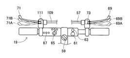
次に、ハンドル19について説明する。図5に表すように、ハンドル19は、自転車と同様のバータイプである。ハンドル19には、イグニッションスイッチ59、走行開始スイッチ61、走行可LED63、速度設定スイッチ65、及び異常表示LED67が設けられている。イグニッションスイッチ59は、自走制御が実行される際に使用されるセレクト型のスイッチである。走行開始スイッチ61は、自走制御が実行される際に使用される押しボタン型のスイッチである。走行可LED63は、自走制御が実行される際に点灯・点滅・消灯のいずれかが行われる表示装置である。速度設定スイッチ65は、自走制御中の最高速度を低速・中速・高速のいずれかに切り替えることができるものである。本実施形態では、高速に切り替えられた際の最高速度は6km/hである。異常表示LED67は、自走制御が実行される際に異常が生じたときに点灯される表示装置である。自走制御については後述する。
さらに、ハンドル19には、図5視右側(前方向に対する右側)において右ブレーキレバー69が取り付けられ、図5視左側(前方向に対する左側)において左ブレーキレバー71が取り付けられている。
右ブレーキレバー69には、右アウターケーブル57の他端部が接続されており、さらに、右アウターケーブル57の中を通っている右インナーケーブル53(図3参照)の他端部が取り付けられている。
右ブレーキレバー69が符号69Aに示された位置に移動すると、右インナーケーブル53のストローク変位が第1所定距離に等しくなり、フロント用第1ブレーキセンサー55(図3参照)がオン動作する。右ブレーキレバー69が符号69Aに示された位置より図5視下側(ハンドル19側)に移動しても、右インナーケーブル53のストローク変位が第1所定距離より大きいので、フロント用第1ブレーキセンサー55がオン動作する。
上述したように、フロント用第1ブレーキセンサー55がオン動作するときは、フロント用ブレーキキャリパー51(図3参照)が作動する。従って、前輪23(図3参照)にブレーキをかける際には、運転者は右ブレーキレバー69を深く握り込むことにより、右ブレーキレバー69が符号69Aに示された位置又は右ブレーキレバー69が符号69Aに示された位置より図5視下側(ハンドル19側)に移動させる。
また、右ブレーキレバー69には、フロント用第2ブレーキセンサー73が設けられている。フロント用第2ブレーキセンサー73は、右ブレーキレバー69が符号69Bに示された位置に移動するとオン動作する。右ブレーキレバー69が符号69Bに示された位置より図5視下側(ハンドル19側)に移動しても、フロント用第2ブレーキセンサー73がオン動作する。運転者は、右ブレーキレバー69を浅く握り込むことにより、右ブレーキレバー69を符号69Bに示された位置にまで移動させることができる。
左ブレーキレバー71には、左アウターケーブル109の他端部が接続されており、さらに、左アウターケーブル109の中を通っている左インナーケーブル105(図4参照)の他端部が取り付けられている。
左ブレーキレバー71が符号71Aに示された位置に移動すると、左インナーケーブル105のストローク変位が第2所定距離に等しくなり、リア用第1ブレーキセンサー107(図4参照)がオン動作する。左ブレーキレバー71が符号71Aに示された位置より図5視下側(ハンドル19側)に移動しても、左インナーケーブル105のストローク変位が第2所定距離より大きいので、リア用第1ブレーキセンサー107がオン動作する。
上述したように、リア用第1ブレーキセンサー107がオン動作するときは、リア用ブレーキキャリパー103(図4参照)が作動する。従って、後輪35(図4参照)にブレーキをかける際には、運転者は左ブレーキレバー71を深く握り込むことにより、左ブレーキレバー71が符号71Aに示された位置又は左ブレーキレバー71が符号71Aに示された位置より図5視下側(ハンドル19側)に移動させる。
また、左ブレーキレバー71には、リア用第2ブレーキセンサー111が設けられている。リア用第2ブレーキセンサー111は、左ブレーキレバー71が符号71Bに示された位置に移動するとオン動作する。左ブレーキレバー71が符号71Bに示された位置より図5視下側(ハンドル19側)に移動しても、リア用第2ブレーキセンサー111がオン動作する。運転者は、左ブレーキレバー71を浅く握り込むことにより、左ブレーキレバー71を符号71Bに示された位置にまで移動させることができる。
次に、シート29について説明する。図6に表すように、シート29には、着座センサー77が内設されている。着座センサー77は、シート29に作用する圧力を検知し、所定値以上の圧力を検知中にオン動作する。本実施形態では、運転者がシート29に着座すると、シート29に所定値以上の圧力が作用することから、着座センサー77がオン動作する。
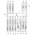
次に、モーター駆動制御ユニット37について説明する。図7に表すように、モーター駆動制御ユニット37は、CPU79、ROM81、及びRAM83を備えている。CPU79は、本実施形態の小型電動車両1全体の制御を行う演算装置及び制御装置である。CPU79には、ROM81及びRAM83が接続されている。ROM81には、各種のプログラム等が記憶されている。例えば、自走制御で使用されるプログラムや速度曲線(加速・減速・定速の各曲線)等は、ROM81に記憶されている。RAM83には、CPU79のデータ処理に必要なデータが一時的に記憶される。
また、CPU79には、フロント用第1ブレーキセンサー55、フロント用第2ブレーキセンサー73、リア用第1ブレーキセンサー107、リア用第2ブレーキセンサー111、着座センサー77、イグニッションスイッチ59、走行開始スイッチ61、速度設定スイッチ65、走行可LED63、及び異常表示LED67が接続されている。さらに、CPU79には、モーター85が接続されている。モーター85は、不図示のバッテリーを駆動源とし、前方向に対する右側の後輪35(図4参照)を電動駆動させる。
[2.自走制御]
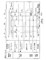
以下、本実施形態の小型電動車両1で実行される自走制御について、図8及び図9を参照しつつ説明する。尚、図8及び図9に表すシーケンスでは、説明の便宜上、「ブレーキレバー」が右ブレーキレバー69又は左ブレーキレバー71に相当し、「第1ブレーキセンサー(キャリパー)」がフロント用第1ブレーキセンサー55又はリア用第1ブレーキセンサー107に相当し、「第2ブレーキセンサー(レバー)」が、フロント用第2ブレーキセンサー73又はリア用第2ブレーキセンサー111に相当する。
以下、本実施形態の小型電動車両1で実行される自走制御について、図8及び図9を参照しつつ説明する。尚、図8及び図9に表すシーケンスでは、説明の便宜上、「ブレーキレバー」が右ブレーキレバー69又は左ブレーキレバー71に相当し、「第1ブレーキセンサー(キャリパー)」がフロント用第1ブレーキセンサー55又はリア用第1ブレーキセンサー107に相当し、「第2ブレーキセンサー(レバー)」が、フロント用第2ブレーキセンサー73又はリア用第2ブレーキセンサー111に相当する。
先ず、小型電動車両1が停止中における自走制御の発進シーケンスについて説明する。図8に表すように、段階A1では、右ブレーキレバー69又は左ブレーキレバー71が放たれているため、フロント用第1ブレーキセンサー55及びフロント用第2ブレーキセンサー73がオン動作していない、或いは、リア用第1ブレーキセンサー107及びリア用第2ブレーキセンサー111がオン動作していない。さらに、運転者がシート29に着座していないため、着座センサー77もオン動作していない。この状態では、走行可LED63の消灯が保たれ、運転者の押下操作によって走行開始スイッチ61が一時的にオン動作しても、モーター制御は行われないため、小型電動車両1の停止が保たれる。
段階A2では、運転者が右ブレーキレバー69又は左ブレーキレバー71を深く握り込む操作が行われる。右ブレーキレバー69を深く握り込む操作が行われた場合には、右ブレーキレバー69が符号69B(図5参照)に示された位置にまで移動した時点でフロント用第2ブレーキセンサー73がオン動作し、右ブレーキレバー69が符号69A(図5参照)に示された位置にまで移動した時点でフロント用第1ブレーキセンサー55がオン動作すると共に走行可LED63が点滅する。又は、左ブレーキレバー71を深く握り込む操作が行われた場合にも、右ブレーキレバー69を深く握り込む操作が行われた場合と同様に作用する。いずれの場合でも、運転者がシート29に着座しているため、着座センサー77がオン動作するが、この状態では、モーター制御は行われないため、小型電動車両1の停止が保たれる。
さらに、段階A2では、運転者が右ブレーキレバー69又は左ブレーキレバー71を放す操作が行われる。右ブレーキレバー69を深く握り込む操作が行われた後、右ブレーキレバー69が放されると、右ブレーキレバー69が符号69Aに示された位置を過ぎた時点でフロント用第1ブレーキセンサー55がオフ動作すると共に走行可LED63が消灯し、右ブレーキレバー69が符号69Bに示された位置を過ぎた時点でフロント用第2ブレーキセンサー73がオフ動作する。又は、左ブレーキレバー71を深く握り込む操作が行われた後、左ブレーキレバー71が放されると、右ブレーキレバー69が放されたときと同様に作用する。いずれの場合でも、この状態では、モーター制御は行われないため、小型電動車両1の停止が保たれる。
尚、段階A2において、運転者が右ブレーキレバー69及び左ブレーキレバー71を深く握り込む操作が行われた状態では、フロント用第1ブレーキセンサー55又はリア用第1ブレーキセンサー107がオン動作すると走行可LED63が点滅し、右ブレーキレバー69又は左ブレーキレバー71が放され、フロント用第1ブレーキセンサー55又はリア用第1ブレーキセンサー107がオフ動作すると、走行可LED63が消灯する。
段階A3では、運転者が右ブレーキレバー69又は左ブレーキレバー71を深く握り込む操作が行われる。右ブレーキレバー69を深く握り込む操作が行われた場合には、右ブレーキレバー69が符号69Bに示された位置にまで移動した時点でフロント用第2ブレーキセンサー73がオン動作し、右ブレーキレバー69が符号69Aに示された位置にまで移動した時点でフロント用第1ブレーキセンサー55がオン動作すると共に走行可LED63が点滅する。又は、左ブレーキレバー71を深く握り込む操作が行われた場合にも、右ブレーキレバー69を深く握り込む操作が行われた場合と同様に作用する。いずれの場合でも、運転者がシート29に着座しているため、着座センサー77がオン動作する。この状態で、運転者の押下操作により走行開始スイッチ61が一時的にオン動作すると、走行可LED63が点灯し、自走予約状態になるが、モーター制御は行われないため、小型電動車両1の停止が保たれる。
さらに、段階A3では、自走予約状態中において、運転者が右ブレーキレバー69又は左ブレーキレバー71を放す操作が行われる。右ブレーキレバー69を深く握り込む操作が行われた後、右ブレーキレバー69が放されると、右ブレーキレバー69が符号69Aに示された位置を過ぎた時点でフロント用第1ブレーキセンサー55がオフ動作する。さらに、右ブレーキレバー69が符号69Bに示された位置を過ぎた時点でフロント用第2ブレーキセンサー73がオフ動作する共に、リア用第1ブレーキセンサー107及びリア用第2ブレーキセンサー111がオフ動作中であることを条件として、モーター制御が開始される。又は、左ブレーキレバー71を深く握り込む操作が行われた後、左ブレーキレバー71が放されると、左ブレーキレバー71が符号71Aに示された位置を過ぎた時点でリア用第1ブレーキセンサー107がオフ動作する。さらに、左ブレーキレバー71が符号71Bに示された位置を過ぎた時点でリア用第2ブレーキセンサー111がオフ動作する共に、フロント用第1ブレーキセンサー55及びフロント用第2ブレーキセンサー73がオフ動作中であることを条件として、モーター制御が開始される。いずれの場合でも、モーター制御が開始されると、このモーター制御により、後輪35(図4参照)が電動駆動されるので、小型電動車両1が発進し、小型電動車両1の自走速度が最高速度まで一律に加速される。そして、小型電動車両1の自走速度が最高速度まで加速されると、小型電動車両1は最高速度で定速自走される。
尚、段階A3において、運転者が右ブレーキレバー69及び左ブレーキレバー71を深く握り込む操作が行われた状態では、フロント用第1ブレーキセンサー55又はリア用第1ブレーキセンサー107がオン動作すると走行可LED63が点滅する。走行可LED63が点滅中に、運転者の押下操作により走行開始スイッチ61が一時的にオン動作すると、走行可LED63が点灯する。この状態で、右ブレーキレバー69及び左ブレーキレバー71が放され、フロント用第2ブレーキセンサー73及びリア用第2ブレーキセンサー111がオフ動作すると、モーター制御が開始される。
モーター制御中は、走行可LED63の点灯が保たれる。さらに、本実施形態のシーケンスでは、説明の便宜上、モーター制御中は運転者がシート29に着座していることとし、着座センサー77のオン動作が保持される。
次に、小型電動車両1が自走中における自走制御の走行シーケンスについて説明する。図9に表すように、段階B1では、モーター制御が行われており、小型電動車両1の最高速度による定速自走中において、運転者が右ブレーキレバー69又は左ブレーキレバー71を浅く握り込む操作が行われる。右ブレーキレバー69を浅く握り込む操作が行われた場合には、右ブレーキレバー69が符号69Bに示された位置にまで移動した時点でフロント用第2ブレーキセンサー73がオン動作する一方、右ブレーキレバー69が符号69Aに示された位置にまで移動しないので、フロント用第1ブレーキセンサー55のオフ動作が保たれる。又は、左ブレーキレバー71を浅く握り込む操作が行われた場合にも、右ブレーキレバー69を浅く握り込む操作が行われた場合と同様に作用する。いずれの場合でも、この状態では、モーター制御により、小型電動車両1の自走速度が予め定められた最低速度(本実施形態では、0km/h)まで一律に減速される。
尚、段階B1において、運転者が右ブレーキレバー69及び左ブレーキレバー71を浅く握り込む操作が行われた状態では、フロント用第2ブレーキセンサー73又はリア用第2ブレーキセンサー111がオン動作すると、モーター制御により、小型電動車両1の自走速度が最低速度の0km/hまで一律に減速される。
さらに、段階B1では、小型電動車両1の減速自走中において、運転者が右ブレーキレバー69又は左ブレーキレバー71を放す操作が行われる。右ブレーキレバー69を放す操作が行われた場合には、右ブレーキレバー69が符号69Bに示された位置を過ぎた時点でフロント用第2ブレーキセンサー73がオフ動作し、フロント用第1ブレーキセンサー55はオフ動作が保たれる。この状態では、リア用第1ブレーキセンサー107及びリア用第2ブレーキセンサー111がオフ動作中であることを条件として、モーター制御により、小型電動車両1の自走速度が最高速度まで一律に加速される。又は、左ブレーキレバー71を放す操作が行われた場合には、左ブレーキレバー71が符号71Bに示された位置を過ぎた時点でリア用第2ブレーキセンサー111がオフ動作し、リア用第1ブレーキセンサー107はオフ動作が保たれる。この状態では、フロント用第1ブレーキセンサー55及びフロント用第2ブレーキセンサー73がオフ動作中であることを条件として、モーター制御により、小型電動車両1の自走速度が最高速度まで一律に加速される。いずれの場合でも、小型電動車両1の自走速度が最高速度まで加速されると、小型電動車両1は最高速度で定速自走される。
尚、段階B1において、運転者が右ブレーキレバー69及び左ブレーキレバー71を浅く握り込む操作が行われた状態では、右ブレーキレバー69及び左ブレーキレバー71が放され、フロント用第2ブレーキセンサー73及びリア用第2ブレーキセンサー111がオフ動作すると、モーター制御により、小型電動車両1の自走速度が最高速度まで一律に加速される。
段階B2では、モーター制御が行われており、小型電動車両1の最高速度による定速自走中において、運転者が右ブレーキレバー69又は左ブレーキレバー71を浅く握り込む操作が段階B1と比べて長く行われる。この操作が行われると、段階B1と同様にして、モーター制御により、小型電動車両1の自走速度が最低速度の0km/hまで一律に減速される。そして、小型電動車両1の自走速度が最低速度の0km/hにまで減速されると、モーター制御により、小型電動車両1は一時停止された状態が保持される。
さらに、段階B2では、小型電動車両1の一時停止中において、運転者が右ブレーキレバー69又は左ブレーキレバー71を放す操作が行われる。これらの操作が行われると、段階B1と同様にして、モーター制御により、小型電動車両1の自走速度が最高速度まで一律に加速される。そして、小型電動車両1の自走速度が最高速度まで加速されると、小型電動車両1は最高速度で定速自走される。
段階B3では、モーター制御が行われており、小型電動車両1の最高速度による定速自走中において、運転者が右ブレーキレバー69又は左ブレーキレバー71を深く握り込む操作が行われる。右ブレーキレバー69を深く握り込む操作が行われた場合には、右ブレーキレバー69が符号69Bに示された位置にまで移動した時点で、フロント用第2ブレーキセンサー73がオン動作すると共に、モーター制御により、小型電動車両1の自走速度が最低速度の0km/hまで一律に減速される。さらに、右ブレーキレバー69が符号69Aに示された位置にまで移動した時点で、フロント用第1ブレーキセンサー55がオン動作し、走行可LED63が点滅すると共に、モーター制御が停止される。又は、左ブレーキレバー71を深く握り込む操作が行われた場合にも、右ブレーキレバー69を深く握り込む操作が行われた場合と同様に作用する。
尚、段階B3において、運転者が右ブレーキレバー69及び左ブレーキレバー71を深く握り込む操作が行われた状態では、フロント用第1ブレーキセンサー55又はリア用第1ブレーキセンサー107がオン動作すると、走行可LED63が点滅すると共に、モーター制御が停止される。
さらに、段階B3では、モーター制御の停止中において、運転者が右ブレーキレバー69又は左ブレーキレバー71を放す操作が行われる。右ブレーキレバー69を放す操作が行われた場合には、右ブレーキレバー69が符号69Aに示された位置を過ぎた時点でフロント用第1ブレーキセンサー55がオフ動作すると共に走行可LED63が消灯し、右ブレーキレバー69が符号69Bに示された位置を過ぎた時点でフロント用第2ブレーキセンサー73がオフ動作する。又は、左ブレーキレバー71を放す操作が行われた場合にも、右ブレーキレバー69を放す操作が行われた場合と同様に作用する。いずれの場合でも、運転者がシート29から離れると、着座センサー77がオフ動作する。
尚、段階B3において、運転者が右ブレーキレバー69及び左ブレーキレバー71を深く握り込む操作が行われた状態では、右ブレーキレバー69又は左ブレーキレバー71が放され、フロント用第1ブレーキセンサー55又はリア用第1ブレーキセンサー107がオフ動作すると、走行可LED63が消灯する。
また、段階B3では、モーター制御が停止されると、モーター85はフリー回転状態に移行すると同時に、フロント用ブレーキキャリパー51又はリア用ブレーキキャリパー103の作動が開始される。つまり、フロント用第1ブレーキセンサー55のオン動作中は、右ブレーキレバー69の握込操作によってフロント用ブレーキキャリパー51が作動するので、手動による制動を前輪23にかけることができる。又は、リア用第1ブレーキセンサー107のオン動作中は、左ブレーキレバー71の握込操作によってリア用ブレーキキャリパー103が作動するので、手動による制動を後輪35にかけることができる。これにより、小型電動車両1が停止される。
また、段階B3では、図には表さないが、走行可LED63の点滅中において、運転者の押下操作により走行開始スイッチ61が一時的にオン動作すると、走行可LED63が点灯し、段階A3における自走予約状態になる。
従って、本実施形態の小型電動車両1では、フロント用第1ブレーキセンサー55をフロント用ブレーキキャリパー51に設けると共にフロント用第2ブレーキセンサー73を右ブレーキレバー69に設けることにより、フロント用第1ブレーキセンサー55とフロント用第2ブレーキセンサー73を独立してオン動作又はオフ動作するようにしている。さらに、リア用第1ブレーキセンサー107をリア用ブレーキキャリパー103に設けると共にリア用第2ブレーキセンサー111を左ブレーキレバー71に設けることにより、リア用第1ブレーキセンサー107とリア用第2ブレーキセンサー111を独立してオン動作又はオフ動作するようにしている。
そして、フロント用第1ブレーキセンサー55、フロント用第2ブレーキセンサー73、リア用第1ブレーキセンサー107、及びリア用第2ブレーキセンサー111のオン動作又はオフ動作の組合せに基づいて、運転者の意思を確認し、発進・加速・最高速度の定速走行・減速・最低速度(本実施形態では、0km/h)の定速走行・停止の各制御タイミングを判別している。さらに、各制御タイミングでは、着座センサー77がオン動作により、安全性確認が行われている。
つまり、本実施形態の小型電動車両1では、走行の開始に当たり、運転者が右ブレーキレバー69又は左ブレーキレバー71を最後まで握り込む操作を行えば、走行可LED63が点滅し、走行可LED63が点滅中に運転者が走行開始スイッチ61を押下すれば、走行予約状態になる。これにより、運転者は、右利きでも左利きでも、握込操作を行い易い利き手を使うことによって、走行予約状態にする操作をスムーズに行うことができる。走行予約状態中において、運転者が右ブレーキレバー69及び左ブレーキレバー71を放した状態にして、ブレーキ解除操作を行えば、モーター制御による発進・加速・最高速度の定速走行が行われる(段階A3)。
その後、運転者が右ブレーキレバー69又は左ブレーキレバー71を浅く握れば、モーター制御による減速が行われるが、運転者が右ブレーキレバー69及び左ブレーキレバー71を放した状態にすることにより、ブレーキ解除操作を行えば、モーター制御による加速・最高速度の定速走行が再び行われる(段階B1)。
さらに、運転者が右ブレーキレバー69又は左ブレーキレバー71を浅く握り続ければ、モーター制御による減速・最低速度(本実施形態では、0km/h)の定速走行が行われるが、その後、運転者が右ブレーキレバー69及び左ブレーキレバー71を放した状態にすることにより、ブレーキ解除操作を行えば、モーター制御による加速・最高速度の定速走行が再び行われる(段階B2)。
さらに、運転者が右ブレーキレバー69又は左ブレーキレバー71を深く握れば、モーター制御による減速が行われた後、手動による制動が前輪23又は後輪35に対して行われると共に、走行可LED63が点滅する(段階B3)。
従って、本実施形態の小型電動車両1では、運転者が右ブレーキレバー69又は左ブレーキレバー71を浅く握り込む操作を行うことで、モーター制御による減速が行われる(各段階B1,B2,B3)。さらに、運転者が右ブレーキレバー69又は左ブレーキレバー71を深く握り込む操作を行うことで、モーター制御による減速に代えて、手動による制動を前輪23又は後輪35にかけることができる(段階B3)。
また、手動による制動が前輪23又は後輪35にかけられている最中は、走行可LED63が点滅している。走行可LED63の点滅中において、運転者が走行開始スイッチ61を押下すると、走行予約状態になる。走行予約状態中において、運転者が右ブレーキレバー69及び左ブレーキレバー71を放した状態にすることにより、ブレーキ解除操作を行うと、モーター制御による発進・加速等が再び行われる(段階B3,A3)。
次に、本実施形態の小型電動車両1で実行される自走制御のプログラムについて、図10乃至図13に表すフローチャートを用いて説明する。自走制御のプログラムは、ROM81に記憶されており、CPU79により実行される。
図10に表すように、CPU79は、この自走制御のプログラムの実行を開始し、イグニッションスイッチ59のオン動作を確認すると(S100)、CPU79自身の異常を確認する(S102)。そして、CPU79自身に異常がある場合には(S104:YES)、CPU79は、異常表示LED67を点灯させ(S106)、CPU79自身の異常を再び確認する(S102)。
又は、CPU79自身に異常がない場合には(S104:NO)、CPU79は、着座センサー77がオン動作されているか否かを判別する(S108)。このとき、異常表示LED67が点灯していれば、CPU79は、異常表示LED67を消灯させる。
ここで、着座センサー77がオン動作されていない場合には(S108:NO)、CPU79は、着座センサー77がオン動作されているか否かを再び判別する(S108)。又は、着座センサー77がオン動作されている場合には(S108:YES)、CPU79は、フロント用第2ブレーキセンサー73及びフロント用第1ブレーキセンサー55がオン動作されているか否かを判別する(S110,S112)。
ここで、フロント用第2ブレーキセンサー73又はフロント用第1ブレーキセンサー55がオン動作されていない場合には(S110:NO,S112:NO)、リア用第2ブレーキセンサー111及びリア用第1ブレーキセンサー107がオン動作されているか否かを判別する(S114,S116)。ここで、リア用第2ブレーキセンサー111又はリア用第1ブレーキセンサー107がオン動作されていない場合には(S114:NO,S116:NO)、CPU79は、着座センサー77がオン動作されているか否かを再び判別する(S108)。
又は、フロント用第2ブレーキセンサー73及びフロント用第1ブレーキセンサー55がオン動作されている場合には(S110:YES,S112:YES)、又はリア用第2ブレーキセンサー111及びリア用第1ブレーキセンサー107がオン動作されている場合には(S114:YES,S116:YES)、CPU79は、走行可LED63を点滅させる(S118)。
その後、CPU79は、走行開始スイッチ61がオン動作されるまで待機する(S120:NO)。そして、走行開始スイッチ61がオン動作されると(S120:YES)、CPU79は、走行可LED63を点灯させる(S122)。
次に、図11に表すように、CPU79は、着座センサー77がオン動作されているか否かを判別する(S124)。ここで、着座センサー77がオン動作されていない場合には(S124:NO)、CPU79は、着座センサー77がオン動作されているか否かを再び判別する(S124)。又は、着座センサー77がオン動作されている場合には(S124:YES)、CPU79は、フロント用第1ブレーキセンサー55がオフ動作されているか否かを判別する(S126)。
ここで、フロント用第1ブレーキセンサー55がオフ動作されていない場合には(S126:NO)、CPU79は、フロント用第1ブレーキセンサー55がオフ動作されているか否かを再び判別する(S126)。又は、フロント用第1ブレーキセンサー55がオフ動作されている場合には(S126:YES)、CPU79は、リア用第1ブレーキセンサー107がオフ動作されているか否かを判別する(S128)。
ここで、リア用第1ブレーキセンサー107がオフ動作されていない場合には(S128:NO)、CPU79は、リア用第1ブレーキセンサー107がオフ動作されているか否かを再び判別する(S128)。又は、リア用第1ブレーキセンサー107がオフ動作されている場合には(S128:YES)、CPU79は、フロント用第2ブレーキセンサー73がオフ動作されているか否かを判別する(S130)。
ここで、フロント用第2ブレーキセンサー73がオフ動作されていない場合には(S130:NO)、CPU79は、フロント用第2ブレーキセンサー73がオフ動作されているか否かを再び判別する(S130)。又は、フロント用第2ブレーキセンサー73がオフ動作されている場合には(S130:YES)、CPU79は、リア用第2ブレーキセンサー111がオフ動作されているか否かを判別する(S132)。
ここで、リア用第2ブレーキセンサー111がオフ動作されていない場合には(S132:NO)、CPU79は、リア用第2ブレーキセンサー111がオフ動作されているか否かを再び判別する(S132)。又は、リア用第2ブレーキセンサー111がオフ動作されている場合には(S132:YES)、CPU79は、モーター加速モードを行う(S134)。
モーター加速モードでは、CPU79は、ROM81に記憶の速度曲線(加速の曲線)に基づいて、モーター85の駆動制御を行うことにより、小型電動車両1の自走速度を加速させる。このとき、小型電動車両1が停止中であれば、小型電動車両1の発進が行われる。
その後、CPU79は、小型電動車両1の自走速度が最高速度に到達しているか否かを判別する(S136)。尚、最高速度は、速度設定スイッチ65で設定された速度であり、RAM83に記憶されている。
ここで、小型電動車両1の自走速度が最高速度に到達している場合には(S136:YES)、CPU79は、モーター最高定速モードを行う(S138)。モーター最高定速モードでは、CPU79は、ROM81に記憶の速度曲線(定速の曲線)に基づいて、モーター85の駆動制御を行うことにより、小型電動車両1の自走速度を最高速度とした定速自走を行う。
又は、小型電動車両1の自走速度が最高速度に到達していない場合(S136:NO)、又はモーター最高定速モードが行われた場合には(S138)、CPU79は、着座センサー77がオン動作されているか否かを判別する(S140)。
ここで、着座センサー77がオン動作されていない場合には(S140:NO)、CPU79は、小型電動車両1の自走速度が最高速度に到達しているか否かを再び判別する(S136)。又は、着座センサー77がオン動作されている場合には(S140:YES)、CPU79は、フロント用第2ブレーキセンサー73又はリア用第2ブレーキセンサー111がオン動作されているか否かを判別する(S142,S144)。
ここで、フロント用第2ブレーキセンサー73及びリア用第2ブレーキセンサー111がオン動作されていない場合には(S142:NO,S144:NO)、CPU79は、小型電動車両1の自走速度が最高速度に到達しているか否かを再び判別する(S136)。又は、フロント用第2ブレーキセンサー73又はリア用第2ブレーキセンサー111がオン動作されている場合には(S142:YES,S144:YES)、図12に表すように、CPU79は、モーター減速モードを行う(S146)。
モーター減速モードでは、CPU79は、ROM81に記憶の速度曲線(減速の曲線)に基づいて、モーター85の駆動制御を行うことにより、小型電動車両1の自走速度を最低速度まで減速させる。本実施形態では、最低速度は、0km/hであり、ROM81に予め記憶されている。尚、モーター減速モード中に、小型電動車両1の自走速度が0km/hになると、小型電動車両1が停止し、その停止状態が保持される。
その後、CPU79は、着座センサー77がオン動作されているか否かを判別する(S148)。
ここで、着座センサー77がオン動作されていない場合には(S148:NO)、CPU79は、着座センサー77がオン動作されているか否かを再び判別する(S148)。又は、着座センサー77がオン動作されている場合には(S148:YES)、CPU79は、フロント用第2ブレーキセンサー73及びリア用第2ブレーキセンサー111がオフ動作されているか否かを判別する(S150,S152)。
ここで、フロント用第2ブレーキセンサー73及びリア用第2ブレーキセンサー111がオフ動作されている場合には(S150:YES,S152:YES)、CPU79は、モーター加速モードを再び行う(S134)。以後、CPU79は、S136以降の処理を行う。又は、フロント用第2ブレーキセンサー73又はリア用第2ブレーキセンサー111がオフ動作されていない場合には(S150:NO,S152:NO)、CPU79は、フロント用第1ブレーキセンサー55又はリア用第1ブレーキセンサー107がオン動作されているか否かを判別する(S154,S156)。
ここで、フロント用第1ブレーキセンサー55及びリア用第1ブレーキセンサー107がオン動作されていない場合には(S154:NO,S156:NO)、CPU79は、着座センサー77がオン動作されているか否かを再び判別する(S148)。又は、フロント用第1ブレーキセンサー55又はリア用第1ブレーキセンサー107がオン動作されている場合には(S154:YES,S156:YES)、CPU79は、図13に表すように、走行可LED63を点滅させる(S158)。
その後、CPU79は、モーターオフの処理を行うことにより(S160)、フリー回転状態でモーター85の停止制御を行う。そして、CPU79は、走行開始スイッチ61がオン動作しているか否かを判別する(S162)。
ここで、走行開始スイッチ61がオン動作している場合には(S162:YES)、CPU79は、走行可LED63を再び点灯させる(S122)。以後、CPU79は、S124以降の処理を行う。又は、走行開始スイッチ61がオン動作していない場合には(S162:NO)、CPU79は、フロント用第1ブレーキセンサー55又はリア用第1ブレーキセンサー107がオフ動作されているか否かを判別する(S164,S166)。
ここで、フロント用第1ブレーキセンサー55及びリア用第1ブレーキセンサー107がオフ動作されていない場合には(S164:NO,S166:NO)、CPU79は、フロント用第1ブレーキセンサー55又はリア用第1ブレーキセンサー107がオフ動作されているか否かを再び判別する(S164,S166)。又は、フロント用第1ブレーキセンサー55又はリア用第1ブレーキセンサー107がオフ動作されている場合には(S164:YES,S166:YES)、CPU79は、走行可LED63を消灯させる(S168)。
その後、CPU79は、フロント用第2ブレーキセンサー73又はリア用第2ブレーキセンサー111がオフ動作されているか否かを判別する(S170,S172)。ここで、フロント用第2ブレーキセンサー73及びリア用第2ブレーキセンサー111がオフ動作されていない場合には(S170:NO,S172:NO)、CPU79は、フロント用第2ブレーキセンサー73又はリア用第2ブレーキセンサー111がオフ動作されているか否かを再び判別する(S170,S172)。又は、フロント用第2ブレーキセンサー73又はリア用第2ブレーキセンサー111がオフ動作されている場合には(S170:YES,S172:YES)、CPU79は、着座センサー77がオフ動作されているか否かを判別する(S174)。
ここで、着座センサー77がオフ動作されていない場合には(S174:NO)、CPU79は、着座センサー77がオフ動作されているか否かを再び判別する(S174)。又は、着座センサー77がオフ動作されている場合には(S174:YES)、CPU79は、この自走制御のプログラムの実行を終了する。
[3.-1 発進時のまとめ] 本実施形態の小型電動車両1では、自走の開始に当たり、運転者は右ブレーキレバー69又は左ブレーキレバー71を深く握り込む操作を行う。この場合において、右ブレーキレバー69が符号69Aに示された位置又は符号69Aに示された位置より図5視下側(ハンドル19側)にあるときに(S112:YES)、運転者が走行開始スイッチ61を押下すると(S120:YES)、自走予約状態となる。或いは、左ブレーキレバー71が符号71Aに示された位置又は符号71Aに示された位置より図5視下側(ハンドル19側)にあるときに(S116:YES)、運転者が走行開始スイッチ61を押下すると(S120:YES)、自走予約状態となる。
自走予約状態において、運転者が右ブレーキレバー69を放したり、右ブレーキレバー69を僅かに握り込む操作を行うと、右ブレーキレバー69が符号69Bに示された位置に向かって移動する。或いは、運転者が左ブレーキレバー71を放したり、左ブレーキレバー71を僅かに握り込む操作を行うと、左ブレーキレバー71が符号71Bに示された位置に向かって移動する。そして、右ブレーキレバー69が符号69Bに示された位置を過ぎ(S130:YES)、且つ、左ブレーキレバー71が符号71Bに示された位置を過ぎたときに(S132:YES)、自走制御プログラムのモーター加速モードが行われる(S134)。
モーター加速モードでは、ROM81に記憶の速度曲線(加速の曲線)に基づいて、モーター85の駆動制御を行うことにより、停止中の小型電動車両1が発進される。よって、右ブレーキレバー69及び左ブレーキレバー71を用いた操作により、自走制御プログラムのモーター加速モードが行われるので、操作性を向上させることができる。
また、自走の開始に当たり、右ブレーキレバー69、左ブレーキレバー71、及び走行開始スイッチ61の一連の操作が必要であることから(S110,S112,S114,S116,S120,S126,S128,S130,S132)、安全性の確認が行われた上で、小型電動車両1を発進させることができる。
さらに、本実施形態の小型電動車両1では、アクセルレバーは備えておらず、自走の開始に当たり、アクセルレバーの操作が不要であることから、アクセルレバーの誤操作等による小型電動車両1の急発進を防止することができる。
[3.-2 加速時のまとめ]
本実施形態の小型電動車両1では、小型電動車両1の自走中において、運転者が右ブレーキレバー69を放したり、右ブレーキレバー69を僅かに握り込む操作を行うことによって、右ブレーキレバー69が符号69Bに示された位置より図5視上側にあり(S142:NO、S150:YES)、且つ、運転者が左ブレーキレバー71を放したり、左ブレーキレバー71を僅かに握り込む操作を行うことによって、左ブレーキレバー71が符号71Bに示された位置より図5視上側にあると(S144:NO、S152:YES)、最高速度まで小型電動車両1の自走速度が加速する(S134,S136,S138)。
本実施形態の小型電動車両1では、小型電動車両1の自走中において、運転者が右ブレーキレバー69を放したり、右ブレーキレバー69を僅かに握り込む操作を行うことによって、右ブレーキレバー69が符号69Bに示された位置より図5視上側にあり(S142:NO、S150:YES)、且つ、運転者が左ブレーキレバー71を放したり、左ブレーキレバー71を僅かに握り込む操作を行うことによって、左ブレーキレバー71が符号71Bに示された位置より図5視上側にあると(S144:NO、S152:YES)、最高速度まで小型電動車両1の自走速度が加速する(S134,S136,S138)。
よって、右ブレーキレバー69が符号69Bに示された位置より図5視上側にあり(S142:NO、S150:YES)、且つ、左ブレーキレバー71が符号71Bに示された位置より図5視上側にある限り(S144:NO、S152:YES)、右ブレーキレバー69及び左ブレーキレバー71の操作に影響されることなく、自走制御プログラムにより、小型電動車両1の加速が最高速度まで行われるので(S134,S136,S138)、円滑な自走が行われると共に、暴走を防止することができる。
[3.-3 減速時のまとめ] 本実施形態の小型電動車両1では、運転者が右ブレーキレバー69をより握り込む操作によって、右ブレーキレバー69が符号69Bに示された位置又は右ブレーキレバー69が符号69Bに示された位置より図5視下側(ハンドル19側)にあると(S142:YES)、或いは、運転者が左ブレーキレバー71をより握り込む操作によって、左ブレーキレバー71が符号71Bに示された位置又は左ブレーキレバー71が符号71Bに示された位置より図5視下側(ハンドル19側)にあると(S144:YES)、自走制御プログラムのモーター減速モードが行われる(S146)。
モーター減速モードでは、ROM81に記憶の速度曲線(減速の曲線)に基づいて、モーター85の駆動制御を行うことにより、小型電動車両1の自走速度が減速する。さらに、右ブレーキレバー69が符号69Aに示された位置より図5視上側にあり(S154:NO)、且つ、左ブレーキレバー71が符号71Aに示された位置より図5視上側にある限り(S156:NO)、自走制御プログラムにより、小型電動車両1の減速が最低速度の0km/hまで行われる(S146)。
よって、今まで慣れ親しんだブレーキレバーの握込操作により、小型電動車両1を減速させることができる。
[3.-4 減速時と制動時の関係のまとめ]
本実施形態の小型電動車両1では、自走の開始後に、運転者が右ブレーキレバー69を深く握り込む操作によって、右ブレーキレバー69が符号69Aに示された位置を過ぎた時点になると(S154:YES)、或いは、運転者が左ブレーキレバー71を深く握り込む操作によって、左ブレーキレバー71が符号71Aに示された位置を過ぎた時点になると(S156:YES)、モーター85が停止制御されることにより小型電動車両1の自走が終了すると共に(S160)、右ブレーキレバー69の操作による手動でのフロント用ブレーキキャリパー51の作動が開始されることにより小型電動車両1の制動が開始され、或いは、左ブレーキレバー71の操作による手動でのリア用ブレーキキャリパー103の作動が開始されることにより小型電動車両1の制動が開始される。よって、小型電動車両1を停止させるための右ブレーキレバー69又は左ブレーキレバー71の操作を、自走制御プログラムでの減速操作から手動での制動操作に直ちに移行させることができる。
本実施形態の小型電動車両1では、自走の開始後に、運転者が右ブレーキレバー69を深く握り込む操作によって、右ブレーキレバー69が符号69Aに示された位置を過ぎた時点になると(S154:YES)、或いは、運転者が左ブレーキレバー71を深く握り込む操作によって、左ブレーキレバー71が符号71Aに示された位置を過ぎた時点になると(S156:YES)、モーター85が停止制御されることにより小型電動車両1の自走が終了すると共に(S160)、右ブレーキレバー69の操作による手動でのフロント用ブレーキキャリパー51の作動が開始されることにより小型電動車両1の制動が開始され、或いは、左ブレーキレバー71の操作による手動でのリア用ブレーキキャリパー103の作動が開始されることにより小型電動車両1の制動が開始される。よって、小型電動車両1を停止させるための右ブレーキレバー69又は左ブレーキレバー71の操作を、自走制御プログラムでの減速操作から手動での制動操作に直ちに移行させることができる。
また、本実施形態の小型電動車両1では、右ブレーキレバー69が符号69Aに示された位置にあるときのレバー操作量は、右ブレーキレバー69による手動での制動操作でフロント用ブレーキキャリパー51の作動が開始する、右ブレーキレバー69のレバー操作量である。右ブレーキレバー69が符号69Bに示された位置にあるときのレバー操作量は、右ブレーキレバー69による手動での制動操作がフロント用ブレーキキャリパー51の作動に影響しない範囲にある、右ブレーキレバー69のレバー操作量である。
左ブレーキレバー71が符号71Aに示された位置にあるときのレバー操作量は、左ブレーキレバー71による手動での制動操作でリア用ブレーキキャリパー103の作動が開始する、左ブレーキレバー71のレバー操作量である。左ブレーキレバー71が符号71Bに示された位置にあるときのレバー操作量は、左ブレーキレバー71による手動での制動操作がリア用ブレーキキャリパー103の作動に影響しない範囲にある、左ブレーキレバー71のレバー操作量である。
よって、自走制御プログラムが実行中において、右ブレーキレバー69が符号69Aに示された位置より図5視上側にあり(S154:NO)、且つ、左ブレーキレバー71が符号71Aに示された位置より図5視上側にある限り(S156:NO)、フロント用ブレーキキャリパー51及びリア用ブレーキキャリパー103を作動させないことができる。又は、右ブレーキレバー69が符号69Aに示された位置にくると(S154:YES)、或いは、左ブレーキレバー71が符号71Aに示された位置にくると(S156:YES)、自走制御プログラムによるモーター減速モード(S146)から、手動によるフロント用ブレーキキャリパー51又はリア用ブレーキキャリパー103の制動に直ちに移行させることができる。
[3.-5 着座判別のまとめ]
本実施形態の小型電動車両1では、着座センサー77がオン動作されているか否かによって、運転者がシート29に着座しているか否かを判別し(S108,S124,S140,S148)、運転者がシート29に着座している場合に限って(S108:YES,S124:YES,S140:YES,S148:YES)、自走制御プログラムを進行させることができる。よって、シート29に運転者が着座していない状態で自走制御プログラムが進行されることを防止できる。
本実施形態の小型電動車両1では、着座センサー77がオン動作されているか否かによって、運転者がシート29に着座しているか否かを判別し(S108,S124,S140,S148)、運転者がシート29に着座している場合に限って(S108:YES,S124:YES,S140:YES,S148:YES)、自走制御プログラムを進行させることができる。よって、シート29に運転者が着座していない状態で自走制御プログラムが進行されることを防止できる。
[4.その他]
本実施形態の小型電動車両1では、自走制御プログラムにおいて、フリー回転状態でモーター85の停止制御が行われる(S160)。つまり、モーター85による自走が終了すると、モーター85で駆動される後輪35が自由に回転できる状態になる。従って、本実施形態の小型電動車両1では、モーター85による自走が終了すると、前輪23及び一対の後輪35を自由に回転させることにより移動できるので、緊急時や折畳状態時等の移動が容易である。
本実施形態の小型電動車両1では、自走制御プログラムにおいて、フリー回転状態でモーター85の停止制御が行われる(S160)。つまり、モーター85による自走が終了すると、モーター85で駆動される後輪35が自由に回転できる状態になる。従って、本実施形態の小型電動車両1では、モーター85による自走が終了すると、前輪23及び一対の後輪35を自由に回転させることにより移動できるので、緊急時や折畳状態時等の移動が容易である。
ちなみに、本実施形態において、走行開始スイッチ61は、「操作スイッチ」の一例である。速度設定スイッチ65は、「設定スイッチ」の一例である。右ブレーキレバー69は、「ブレーキレバー」の一例である。右ブレーキレバー69が符号69Aに示された位置にあるときのレバー操作量は、「第1操作量」の一例である。右ブレーキレバー69が符号69Bに示された位置にあるときのレバー操作量は、「第2操作量」の一例である。左ブレーキレバー71は、「ブレーキレバー」の一例である。左ブレーキレバー71が符号71Aに示された位置にあるときのレバー操作量は、「第1操作量」の一例である。左ブレーキレバー71が符号71Bに示された位置にあるときのレバー操作量は、「第2操作量」の一例である。シート29は、「座席」の一例である。
[5.変更例]
尚、本発明は上記実施形態に限定されるものでなく、その趣旨を逸脱しない範囲で様々な変更が可能である。
例えば、本実施形態の小型電動車両1は、ディレイタイマを備えてもよい。ディレイタイマは、着座センサー77の出力信号について、運転者がシート29に着座していないと判別される動作の継続時間が所定時間未満であることを示す信号を無効とする。よって、例えば、シート29に着座している運転者が腰を一瞬浮かしたり、小型電動車両1が振動すること等により、着座センサー77の出力信号にチャタリングが発生した場合において、着座センサー77の出力信号に基づく自走制御プログラムの進行不能を防止することができる。これにより、操作性が向上する。ちなみに、ディレイタイマは、「誤検知防止部」の一例である。
尚、本発明は上記実施形態に限定されるものでなく、その趣旨を逸脱しない範囲で様々な変更が可能である。
例えば、本実施形態の小型電動車両1は、ディレイタイマを備えてもよい。ディレイタイマは、着座センサー77の出力信号について、運転者がシート29に着座していないと判別される動作の継続時間が所定時間未満であることを示す信号を無効とする。よって、例えば、シート29に着座している運転者が腰を一瞬浮かしたり、小型電動車両1が振動すること等により、着座センサー77の出力信号にチャタリングが発生した場合において、着座センサー77の出力信号に基づく自走制御プログラムの進行不能を防止することができる。これにより、操作性が向上する。ちなみに、ディレイタイマは、「誤検知防止部」の一例である。
また、本実施形態の小型電動車両1は、運転者がハンドル19を把持していることを確認するためのセンサーを備えてもよい。そのセンサーは、静電センサー又は感圧センサー等であり、運転者がハンドル19を把持する箇所に内設される。これにより、安全性が向上する。
また、本実施形態の小型電動車両1は、前方向の障害物を見つけ出すためのセンサーを備えてもよい。そのセンサーは、レザーセンサー、超音波センサー、又はカメラセンサー等であり、前方向を遮らない箇所に装着される。これにより、安全性が向上する。
また、本実施形態では、フロント用第1ブレーキセンサー55及びフロント用第2ブレーキセンサー73のみを使用して自走制御プログラムを実行させてもよいし、或いは、リア用第1ブレーキセンサー107及びリア用第2ブレーキセンサー111のみを使用して自走制御プログラムを実行させてもよい。
また、本実施形態では、左右のブレーキレバー69,71の手動操作による制動は、左右のアウターケーブル57,109等を介して行われるが、ブレーキフルードの油圧等を介して行われてもよい。また、フロント用ブレーキキャリパー51及びリア用ブレーキキャリパー103は、ドラムブレーキ等に置き換えられてもよい。
また、本実施形態では、左右のブレーキレバー69,71に代えて、ブレーキペダルを備えてもよい。
また、本実施形態の小型電動車両1は、自走速度を測定するための速度センサーを備えてもよい。その速度センサーは、自走制御プログラムの実行中においてモーター85を制御する際に使用される(S134,S136,S138,S146)。
また、本実施形態の小型電動車両1は、最低速度を切り替えるための設定スイッチをハンドル19等に備えてもよい。この設定スイッチによって、自走制御中の最低速度を低速・中速・高速のいずれかに切り替えるようにしてもよい。さらに、最低速度の低速は、0km/hとしてもよい。
また、本実施形態では、速度設定スイッチ65で高速に切り替えられた際の自走制御中の最高速度は、6km/hであるが、6km/hより速くてもよい。
1 小型電動車両
29 シート
51 フロント用ブレーキキャリパー
55 フロント用第1ブレーキセンサー
61 走行開始スイッチ
65 速度設定スイッチ
69 右ブレーキレバー
71 左ブレーキレバー
73 フロント用第2ブレーキセンサー
77 着座センサー
79 CPU
81 ROM
83 RAM
85 モーター
103 リア用ブレーキキャリパー
107 リア用第1ブレーキセンサー
111 リア用第2ブレーキセンサー
29 シート
51 フロント用ブレーキキャリパー
55 フロント用第1ブレーキセンサー
61 走行開始スイッチ
65 速度設定スイッチ
69 右ブレーキレバー
71 左ブレーキレバー
73 フロント用第2ブレーキセンサー
77 着座センサー
79 CPU
81 ROM
83 RAM
85 モーター
103 リア用ブレーキキャリパー
107 リア用第1ブレーキセンサー
111 リア用第2ブレーキセンサー
Claims (8)
- 自走の開始を指令する操作スイッチと、
ブレーキレバーのレバー操作量を検出するブレーキセンサーと、
車両を自走させるモーターとを備え、
自走の開始に当たり、前記レバー操作量が第1操作量以上である場合に前記操作スイッチがオンされると自走予約状態となり、
前記自走予約状態において前記レバー操作量が前記第1操作量より小さい第2操作量未満になると、前記モーターの駆動制御による自走制御が開始されることを特徴とする小型電動車両。 - 前記自走制御は、前記レバー操作量が前記第2操作量未満の場合には、予め定められた最高速度まで前記車両の自走速度を加速することを特徴とする請求項1に記載の小型電動車両。
- 前記自走制御は、前記レバー操作量が前記第2操作量以上で前記第1操作量未満の場合には、予め定められた最低速度まで前記車両の自走速度を減速することを特徴とする請求項1又は請求項2に記載の小型電動車両。
- 自走の開始後に、前記レバー操作量が前記第1操作量以上になると、前記モーターが停止制御されることにより前記自走制御が終了すると共に、前記ブレーキレバーによる手動での制動操作が行われることを特徴とする請求項1乃至請求項3のいずれか一つに記載の小型電動車両。
- 前記最高速度を切り替える設定スイッチを備えることを特徴とする請求項2に記載の小型電動車両。
- 前記第1操作量は、前記ブレーキレバーによる手動での制動操作でブレーキキャリパーの作動が開始する前記ブレーキレバーの前記レバー操作量であり、
前記第2操作量は、前記ブレーキレバーによる手動での制動操作が前記ブレーキキャリパーの作動に影響しない範囲にある前記ブレーキレバーの前記レバー操作量であることを特徴とする請求項1乃至請求項5のいずれか一つに記載の小型電動車両。 - 座席に取り付けられた着座センサーを備え、
前記着座センサーの出力信号に基づいて前記座席に運転者が着座していると判別される場合に前記自走制御が実行可能とされることを特徴とする請求項1乃至請求項6のいずれか一つに記載の小型電動車両。 - 前記着座センサーの出力信号について、1つの状態の継続時間が所定時間未満であることを示す信号を無効とする誤検知防止部を備えることを特徴とする請求項7に記載の小型電動車両。
Applications Claiming Priority (2)
| Application Number | Priority Date | Filing Date | Title |
|---|---|---|---|
| JP2016004225A JP6514120B2 (ja) | 2016-01-13 | 2016-01-13 | 小型電動車両 |
| JP2016-004225 | 2016-01-13 |
Publications (1)
| Publication Number | Publication Date |
|---|---|
| WO2017122374A1 true WO2017122374A1 (ja) | 2017-07-20 |
Family
ID=59312148
Family Applications (1)
| Application Number | Title | Priority Date | Filing Date |
|---|---|---|---|
| PCT/JP2016/069237 Ceased WO2017122374A1 (ja) | 2016-01-13 | 2016-06-29 | 小型電動車両 |
Country Status (2)
| Country | Link |
|---|---|
| JP (1) | JP6514120B2 (ja) |
| WO (1) | WO2017122374A1 (ja) |
Citations (3)
| Publication number | Priority date | Publication date | Assignee | Title |
|---|---|---|---|---|
| JPS5615843Y2 (ja) * | 1975-12-19 | 1981-04-14 | ||
| JPH09163512A (ja) * | 1995-12-08 | 1997-06-20 | Kubota Corp | 小型電動車の走行制御装置 |
| JPH10243505A (ja) * | 1997-02-26 | 1998-09-11 | Daiwa Sangyo:Kk | 電動二輪駆動車に於ける駆動制御方法と該駆動制御方法を用いた三輪電動自転車及び四輪電動ワゴン車 |
-
2016
- 2016-01-13 JP JP2016004225A patent/JP6514120B2/ja active Active
- 2016-06-29 WO PCT/JP2016/069237 patent/WO2017122374A1/ja not_active Ceased
Patent Citations (3)
| Publication number | Priority date | Publication date | Assignee | Title |
|---|---|---|---|---|
| JPS5615843Y2 (ja) * | 1975-12-19 | 1981-04-14 | ||
| JPH09163512A (ja) * | 1995-12-08 | 1997-06-20 | Kubota Corp | 小型電動車の走行制御装置 |
| JPH10243505A (ja) * | 1997-02-26 | 1998-09-11 | Daiwa Sangyo:Kk | 電動二輪駆動車に於ける駆動制御方法と該駆動制御方法を用いた三輪電動自転車及び四輪電動ワゴン車 |
Also Published As
| Publication number | Publication date |
|---|---|
| JP2017127094A (ja) | 2017-07-20 |
| JP6514120B2 (ja) | 2019-05-15 |
Similar Documents
| Publication | Publication Date | Title |
|---|---|---|
| CN102510826B (zh) | 用于在踏板传动式交通工具中调节再生利用的装置和方法 | |
| ES2839475T3 (es) | Procedimiento de control y controlador para el ajuste de una velocidad de asistencia a la tracción de una bicicleta eléctrica | |
| WO2019025886A1 (ja) | 制御装置、車体挙動制御システム、モータサイクル、及び、制御方法 | |
| JP6229221B2 (ja) | ステアリングハンドル並びにそのステアリングハンドルを使用した自動車の制御装置及び制御方法 | |
| JP2017100541A (ja) | 電動補助自転車 | |
| JP2012157097A (ja) | 電動車両の制御装置 | |
| JP2009183407A (ja) | 歩行補助装置 | |
| JP7223573B2 (ja) | 鞍乗型車両のライダー支援システムのための処理装置及び処理方法、鞍乗型車両のライダー支援システム、及び、鞍乗型車両 | |
| US10800489B2 (en) | Straddled vehicle | |
| JP2020029176A (ja) | 制御装置及び制御方法 | |
| JP2013233893A (ja) | 走行制御装置 | |
| JP2016185235A (ja) | 歩行補助車および歩行補助車を制御するためのプログラム | |
| JPWO2022185698A5 (ja) | ||
| WO2020217133A1 (ja) | 制御装置及び制御方法 | |
| JP6907137B2 (ja) | 小型電動車両 | |
| JP2017226267A (ja) | 電動駐車ブレーキ装置 | |
| JP6562717B2 (ja) | 電動補助自転車 | |
| JP2008044565A (ja) | 電動車及び電動補助自転車 | |
| WO2017122374A1 (ja) | 小型電動車両 | |
| WO2023053022A1 (ja) | 制御装置及び制御方法 | |
| JP6752083B2 (ja) | 小型電動車両 | |
| JPH10165454A (ja) | 小型電動車 | |
| JP7766670B2 (ja) | 鞍乗り型電動車両 | |
| JP6546789B2 (ja) | 電動補助自転車 | |
| JP3234964U (ja) | ブレーキシステム |
Legal Events
| Date | Code | Title | Description |
|---|---|---|---|
| 121 | Ep: the epo has been informed by wipo that ep was designated in this application |
Ref document number: 16884977 Country of ref document: EP Kind code of ref document: A1 |
|
| NENP | Non-entry into the national phase |
Ref country code: DE |
|
| 32PN | Ep: public notification in the ep bulletin as address of the adressee cannot be established |
Free format text: NOTING OF LOSS OF RIGHTS PURSUANT TO RULE 112(1) EPC (EPO FORM 1205A DATED 10.10.2018) |
|
| 122 | Ep: pct application non-entry in european phase |
Ref document number: 16884977 Country of ref document: EP Kind code of ref document: A1 |