WO2017119328A1 - バーハンドル車両用液圧マスタシリンダ装置 - Google Patents
バーハンドル車両用液圧マスタシリンダ装置 Download PDFInfo
- Publication number
- WO2017119328A1 WO2017119328A1 PCT/JP2016/088613 JP2016088613W WO2017119328A1 WO 2017119328 A1 WO2017119328 A1 WO 2017119328A1 JP 2016088613 W JP2016088613 W JP 2016088613W WO 2017119328 A1 WO2017119328 A1 WO 2017119328A1
- Authority
- WO
- WIPO (PCT)
- Prior art keywords
- master cylinder
- adjustment bolt
- spring member
- hydraulic master
- knocker
- Prior art date
- Legal status (The legal status is an assumption and is not a legal conclusion. Google has not performed a legal analysis and makes no representation as to the accuracy of the status listed.)
- Ceased
Links
Images






Classifications
-
- B—PERFORMING OPERATIONS; TRANSPORTING
- B60—VEHICLES IN GENERAL
- B60T—VEHICLE BRAKE CONTROL SYSTEMS OR PARTS THEREOF; BRAKE CONTROL SYSTEMS OR PARTS THEREOF, IN GENERAL; ARRANGEMENT OF BRAKING ELEMENTS ON VEHICLES IN GENERAL; PORTABLE DEVICES FOR PREVENTING UNWANTED MOVEMENT OF VEHICLES; VEHICLE MODIFICATIONS TO FACILITATE COOLING OF BRAKES
- B60T11/00—Transmitting braking action from initiating means to ultimate brake actuator without power assistance or drive or where such assistance or drive is irrelevant
- B60T11/10—Transmitting braking action from initiating means to ultimate brake actuator without power assistance or drive or where such assistance or drive is irrelevant transmitting by fluid means, e.g. hydraulic
- B60T11/16—Master control, e.g. master cylinders
- B60T11/18—Connection thereof to initiating means
-
- B—PERFORMING OPERATIONS; TRANSPORTING
- B62—LAND VEHICLES FOR TRAVELLING OTHERWISE THAN ON RAILS
- B62L—BRAKES SPECIALLY ADAPTED FOR CYCLES
- B62L3/00—Brake-actuating mechanisms; Arrangements thereof
-
- B—PERFORMING OPERATIONS; TRANSPORTING
- B62—LAND VEHICLES FOR TRAVELLING OTHERWISE THAN ON RAILS
- B62L—BRAKES SPECIALLY ADAPTED FOR CYCLES
- B62L3/00—Brake-actuating mechanisms; Arrangements thereof
- B62L3/02—Brake-actuating mechanisms; Arrangements thereof for control by a hand lever
Definitions
- the present invention relates to a hydraulic master cylinder device for a bar handle vehicle that generates a hydraulic pressure in a hydraulic master cylinder attached to a handle bar of various bar handle vehicles to operate a brake or a clutch.
- the present invention relates to a hydraulic master cylinder device for a bar handle vehicle, which is provided with an adjusting bolt for adjusting a grip margin formed between an operation lever pivotally attached to the handlebar and a grip provided on the front end side of the handlebar.
- an operation lever pivotally attached to a cylinder body of the hydraulic master cylinder is provided with a lever main body disposed along the front side of the grip body, the lever main body, It is divided into a knocker disposed between the cylinder hole and the opening of the cylinder hole formed in the cylinder body, and a grip margin formed between the operation lever and the grip is adjusted between the lever body and the knocker.
- an adjustment bolt was arranged (for example, see Patent Document 1).
- Patent Document 1 it is possible to easily adjust the grip margin formed between the lever body and the grip by turning the adjustment bolt to adjust the amount of protrusion in the knocker direction.
- the adjustment bolt can be adjusted from a shortest protrusion amount to the maximum protrusion amount, the protrusion amount is adjusted by a series of rotation operations, and the grip margin is adjusted steplessly. It was difficult to feel the operation.
- an object of the present invention is to provide a hydraulic master cylinder device for a bar handle vehicle in which a driver can adjust a grip margin well while realizing a grip margin adjustment operation using an adjustment bolt.
- a hydraulic master cylinder device for a bar handle vehicle includes a hydraulic master cylinder attached to a handle bar, and an operation lever pivotally attached to a cylinder body of the hydraulic master cylinder.
- the operation lever is divided into a lever main body disposed in front of a grip provided on a distal end side of a handle bar and a knocker that pushes a piston of the hydraulic master cylinder, and the lever A grip formed between the operation lever and the grip is formed by screwing an adjustment bolt that contacts the knocker into an adjustment bolt mounting portion provided on the main body so that the protrusion amount can be adjusted, and rotating the adjustment bolt.
- the adjustment bolt is provided with the adjustment bolt remover.
- a male screw part that is screwed into a female screw hole formed in the part and is screwed so as to be adjustable toward the knocker, and a knocker contact part that is provided at one end of the male screw part and contacts the knocker
- a handle portion provided at the other end of the male screw portion, the handle portion including a rotary shaft formed in a polygonal column shape and an operation portion for rotating the adjustment bolt, and the adjustment bolt
- a spring member that is elastically pressed against the flat portion of the rotating shaft is attached to the mounting portion, and the spring member is connected to the angle of the rotating shaft from the first flat portion that is in pressure contact with the rotation of the rotating shaft. It is characterized in that a click feeling is given by overcoming the part and pressing against the second plane part.
- a push rod is interposed between the piston and the knocker, and the knocker pushes the piston via the push rod.
- a hydraulic master cylinder attached to the handlebar; and an operation lever pivotally attached to a cylinder body of the hydraulic master cylinder.
- the adjustment bolt mounting portion provided on the operation lever includes the hydraulic master An adjustment bolt that contacts the piston of the cylinder or a push rod that pushes the piston is screwed so that the amount of protrusion can be adjusted, and the adjustment bolt is rotated so that the adjustment lever and the handlebar are provided at the front end side.
- the adjustment bolt is screwed into a female screw hole formed in the adjustment bolt mounting portion, and the piston or push A male threaded portion that is screwed toward the rod so that the amount of protrusion can be adjusted, and provided at one end of the male threaded portion.
- the handle portion includes a rotary shaft formed in a polygonal column shape, and the adjustment bolt.
- a spring member that elastically presses against the flat portion of the rotating shaft, and the spring member presses in accordance with the rotation of the rotating shaft. It is characterized in that a click feeling is imparted by overcoming a corner portion of the rotation shaft from the first plane portion and pressing against the second plane portion.
- the adjustment bolt mounting portion is provided with a spring member mounting portion and a spring member latching portion facing each other with the female screw hole interposed therebetween, and the spring member is formed by bending an elastic wire, and the spring member A linear mounting portion that is attached to the mounting portion, and the flat portion that extends from both ends of the mounting portion across the rotation shaft of the adjustment bolt screwed into the female screw hole and that faces the rotation shaft It is preferable that a pair of spring pieces that are in pressure contact with each other, and a latch piece provided at the tip of each spring piece and latched on the spring member latch portion.
- the pair of spring pieces each have a first curved portion that is convex in a direction approaching the center portion, and in a direction away from each other on the proximal end side and the distal end side of the first curved portion.
- first curved portion is in pressure contact with the flat portion.
- the spring member pressed against the first flat portion of the rotation shaft is By elastically deforming and overcoming the corners of the rotating shaft and pressing against the second plane portion to give a click feeling, the driver can feel the grip allowance adjustment operation with the click feeling provided, and realize the grip allowance. Can be adjusted satisfactorily.
- the adjustment bolt mounting portion is provided with the spring member mounting portion and the spring member latching portion facing each other with the female screw hole interposed therebetween, and the spring member is formed by bending an elastic wire and is attached to the spring member mounting portion.
- a linear mounting portion a pair of spring pieces that extend from both ends of the mounting portion with the rotation shaft sandwiched therebetween and press-contact with the opposing flat portions of the rotation shaft, and spring tips provided at the tip portions of the spring pieces.
- the pair of spring pieces are respectively formed with first curved portions that are convex in the direction of approaching each other at the central portion, and are convex in the directions away from each other on the proximal end side and the distal end side of the first curved portion.
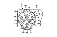
- FIG. 5 is a VV cross-sectional view of FIG. 4.
- FIG. 6 is a view taken along arrow VI-VI in FIG. 5.
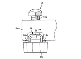
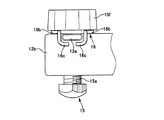
- FIG. 6 is a view taken along arrow VI-VI in FIG. 5 in a state where the adjustment bolt is rotated. It is one side view of the state which attached the adjusting bolt to the adjusting bolt attaching part which shows the 1st form example of this invention.
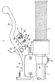
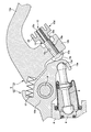
- FIGS. 1 to 11 are views showing a first embodiment in which the present invention is applied to a hydraulic master cylinder device for a front brake of a bar handle vehicle.
- the hydraulic master cylinder device 1 of the present embodiment is a vehicle body front portion.
- a hydraulic master cylinder 4 attached in the vicinity of the accelerator grip 3 of the handlebar 2 for steering a front wheel (not shown), an operation lever 5 attached to the hydraulic master cylinder 4, and a push interposed therebetween Rod 6.
- the hydraulic master cylinder 4 is a reservoir-integrated type having a reservoir 7 in the upper part of the cylinder body 4a, and the handle bar 2 is held by a mounting bracket 4b and a holder 8 formed integrally with the cylinder body 4a. Fastened at 8a and 8a, the handlebar 2 is disposed on the front side of the vehicle body.
- a pair of upper and lower lever brackets 4c, 4c are extended on the vehicle body front side of the cylinder body 4a, and an operation lever 5 is pivotally attached to the lever brackets 4c, 4c.
- the cylinder body 4a is provided with a bottomed cylinder hole 4d that opens on the operation lever side, and a piston 9 is inserted into the cylinder hole 4d through the cup seals 9a and 9b so as to be movable.
- a hydraulic chamber 10 is defined between the bottom wall of the hole.
- a return spring 11 is contracted between the bottom wall of the cylinder hole 4d and the piston 9, and the piston 9 is always urged toward the opening of the cylinder hole 4d by the elastic force of the return spring 11,
- the retreat limit of the piston 9 is regulated by a stopper piece 13c of a knocker 13 (to be described later) coming into contact with the cylinder body 4a via the push rod 6.
- the operating lever 5 is disposed in front of the accelerator grip 3 and is divided into a lever body 12 having a grip portion 12a and a knocker 13 having a working arm 13a that contacts the rear end portion of the push rod 6.
- Each of the two-piece types is pivotally attached to the lever bracket 4c of the cylinder body 4a using a pivot 14.
- the lever main body 12 includes a pivot base portion through which the pivot 14 is inserted, and the grip portion 12a extending from the pivot base portion toward the vehicle body front side of the accelerator grip 3, and on the pivot base side of the grip portion 12a.
- the adjustment bolt mounting portion 12b is formed with a female screw hole 12c that is opened through the cylinder hole side surface and the anti-cylinder hole side surface.
- the spring member latching portion 12e are provided to face each other with the female screw hole 12c interposed therebetween.
- the knocker 13 includes a rotation base 13b, the working arm 13a, and a stopper piece 13c that protrudes from the rotation base 13b toward the front side wall of the cylinder body 4a.
- the working arm 13a is provided with a push rod abutting portion 13d that abuts against the push rod 6 on the side surface of the cylinder hole, and an adjustment bolt abutting surface 13e that abuts against the adjusting bolt 15 on the side surface opposite to the cylinder hole.
- the lever body 12 and the knocker 13 are urged counterclockwise in FIG. 1 with the pivot 14 as a fulcrum by the contact between the working arm 13a and the push rod 6, and the rotation limit during non-braking is limited to the stopper piece. 13c and the cylinder body 4a are regulated by contact with the vehicle body front side wall.
- a spring 17 is contracted on the vehicle body front side of the lever main body 12 and the knocker 13, and due to the elastic force of the spring 17, the adjustment bolt 15 is always in contact with the adjustment bolt contact surface 13e. The backlash of the lever main body 12 is suppressed.
- the adjustment bolt 15 is screwed into a female screw hole 12c provided in the adjustment bolt mounting portion 12b, and is screwed into the knocker 13 so that the protrusion amount can be adjusted, and provided at one end of the male screw portion 15a.
- a handle portion 15d that is caulked and fixed to a small diameter shaft portion 15c provided at the other end of the male screw portion 15a.
- the handle portion 15d has a rotating shaft 15e formed in a hexagonal column shape on the male screw portion side, and a large-diameter operation portion 15f for rotating the adjustment bolt 15 on the distal end side.
- a convex portion 15g protruding outward is formed at a corner portion of the shaft 15e.
- the spring member 16 is formed by bending an elastic wire, and is attached to a linear mounting portion 16a, a pair of spring pieces 16b and 16b extending from both ends of the mounting portion 16a, and a distal end portion of each spring piece 16b. There are provided latching pieces 16c, 16c.
- the pair of spring pieces 16b are formed with a first curved portion 16d that protrudes in a direction approaching each other at the center, and are spaced apart from each other on the proximal end side and the distal end side of the first curved portion 16d.
- Two second curved portions 16e, 16e that are convex in the direction are formed.
- the mounting portion 16a is attached to the spring member attaching portion 12d, the pair of spring pieces 16b and 16b are disposed with the rotating shaft 15e of the adjusting bolt 15 interposed therebetween, and the latching pieces 16c and 16c are latched by the spring member.
- the first curved portions 16d, 16d of the spring pieces 16b, 16b are elastically pressed against the opposing first flat portions 15h, 15h of the rotating shaft 15e, respectively.
- the grip margin formed between the accelerator grip 3 and the grip portion 12a of the operation lever 5 is expanded or contracted by the screwing amount of the adjusting bolt 15 into the female screw hole 12c.
- the grip margin is the smallest. From this state, when the operating portion 15f is rotated to screw the adjusting bolt 15 into the female screw hole 12c and the male screw portion 15a protrudes toward the knocker 13, the lever main body 12 has the pivot 14 as a fulcrum as a fulcrum.
- the adjustment bolt 15 shown in FIG. 11 is most screwed in, the grip margin is maximized.
- the adjustment bolt mounting portion 12b is provided with a spring member mounting portion 12d and a spring member latching portion 12e facing each other with the female screw hole 12c interposed therebetween, and the spring member 16 includes a mounting portion 16a attached to the spring member mounting portion.
- the pair of spring pieces 16b, 16b are respectively formed with first curved portions 16d that protrude in the direction of approaching each other at the center, and are spaced apart from each other on the proximal end side and the distal end side of the first curved portion 16d. Since the two second curved portions 16e and 16e that are convex in the direction to be formed are formed, the spring piece is elastically deformed well with the rotation of the rotating shaft 15e, and a good click feeling can be obtained. .
- FIG. 12 shows a second embodiment of the present invention. Components that are the same as those in the first embodiment are denoted by the same reference numerals, and detailed description thereof is omitted.
- the hydraulic master cylinder device 21 of the present embodiment includes a hydraulic master cylinder 4, an operation lever 22 attached to the hydraulic master cylinder 4, and a push rod 6 interposed therebetween,
- the piston (not shown) of the pressure master cylinder 4 has its retreat limit regulated by a regulating member (not shown) such as a C clip.
- the operating lever 22 is disposed in front of the accelerator grip 3 and includes a turning base portion 22a and a grip portion 22b extending from the turning base portion 22a to the front side of the accelerator grip 3 toward the vehicle body.
- An adjustment bolt mounting portion 22c for screwing an adjustment bolt 23 that adjusts the grip allowance protrudes from the grip side surface of the rotating base side of 22b.
- the adjusting bolt 23 is screwed into a female screw hole 22d provided in the adjusting bolt mounting portion 22c, and is screwed to the push rod 6 so that the protrusion amount can be adjusted, and one end of the male screw portion 23a.
- a push rod abutting portion 23b that abuts against the push rod 6 and a handle portion 23d that is caulked and fixed to a small-diameter shaft portion 23c provided at the other end of the male screw portion 23a.
- the handle portion 23d is integrally provided with a rotary shaft 23e that is arranged on the male screw portion side and formed in a hexagonal column shape, and a large-diameter operation portion 23f that is arranged on the distal end side and rotates the adjusting bolt 23. Further, the same spring member 16 as that in the first embodiment is mounted on the adjustment bolt mounting portion 22c.
- the operating lever 22 pivots.
- the grip margin is expanded.
- the driver can obtain a click feeling by elastic deformation of the spring member 16 every time the operating portion 23f is rotated by a predetermined amount, as in the first embodiment.
- the grip allowance can be adjusted well while realizing the grip allowance adjusting operation.
- the spring member is a first member in which a spring piece that is elastically pressed against the flat portion of the rotating shaft of the handle portion is pressed in accordance with the rotation of the rotating shaft.
- the shape is arbitrary as long as it can be clicked from the plane portion of 1 and over the corner portion of the rotation axis and pressed against the second plane portion to give a click feeling. It may be elastically pressed.
- bolt does not need to form not only the hexagonal column shape but the polygonal column shape, and may not form the convex part in a corner
- the structure of the hydraulic master cylinder of the present invention is arbitrary and can be applied to a hydraulic master cylinder for a clutch.
- the piston of the hydraulic master cylinder is pushed by the operation lever via the push rod.
- the present invention is not limited to this, and the piston is pushed directly by the knocker or the operation lever. It can be anything.
Landscapes
- Engineering & Computer Science (AREA)
- Mechanical Engineering (AREA)
- Transportation (AREA)
- Mechanical Control Devices (AREA)
- Transmission Of Braking Force In Braking Systems (AREA)
- Braking Elements And Transmission Devices (AREA)
Abstract
運転者がアジャストボルトによる握り代調整操作を実感しながら、握り代を良好に調整することができるバーハンドル車両用液圧マスタシリンダ装置であって、アジャストボルトは、アジャストボルト取付部12bの雌ねじ孔12cに螺合し、ノッカー13に向けて突出量調整可能に螺着する雄ねじ部15aと、雄ねじ部15aの一端部に設けたノッカー当接部15bと、雄ねじ部15aの他端部に設けたハンドル部15dとを有し、ハンドル部15dは、多角柱状に形成した回転軸15eと、アジャストボルト15を回動させる操作部15fとを備える。アジャストボルト取付部12bに、回転軸15eの平面部15hに弾性的に圧接するスプリング部材16を取り付け、スプリング部材16は、回転軸15eの回転に伴って圧接している第1の平面部15hから、凸部15gを乗り越え、第2の平面部15iに圧接してクリック感を付与する。
Description
本発明は、各種バーハンドル車両のハンドルバーに取り付けた液圧マスタシリンダに、液圧を発生させてブレーキやクラッチを作動するバーハンドル車両用液圧マスタシリンダ装置に関し、詳しくは、液圧マスタシリンダに枢着される操作レバーと、ハンドルバーの先端側に設けられたグリップとの間に形成される握り代を調整するアジャストボルトを備えたバーハンドル車両用液圧マスタシリンダ装置に関する。
従来、バーハンドル車両用液圧マスタシリンダ装置として、液圧マスタシリンダのシリンダボディに枢着される操作レバーを、グリップの車体前部側に沿って配設されるレバー本体と、該レバー本体及び前記シリンダボディに形成されたシリンダ孔の開口部との間に配設されるノッカーとに分割し、レバー本体とノッカーとの間に、操作レバーとグリップの間に形成される握り代を調整するアジャストボルトを配置したものがあった(例えば、特許文献1参照。)。
しかし、上述の特許文献1のものでは、アジャストボルトを回動してノッカー方向への突出量を調整することにより、レバー本体とグリップとの間に形成される握り代を簡単に調整することができるものの、アジャストボルトは、最短の突出量から最大の突出量まで、一連の回動操作で突出量が調整され、無段階で握り代が調整されることから、運転者が握り代の調整量操作を実感し難かった。
そこで、本発明は、運転者がアジャストボルトによる握り代調整操作を実感しながら、握り代を良好に調整することができるバーハンドル車両用液圧マスタシリンダ装置を提供することを目的としている。
上記目的を達成するため、本発明のバーハンドル車両用液圧マスタシリンダ装置は、ハンドルバーに取着される液圧マスタシリンダと、該液圧マスタシリンダのシリンダボディに枢着される操作レバーとを備え、前記操作レバーは、ハンドルバーの先端側に設けられたグリップの前方に配置されるレバー本体と、前記液圧マスタシリンダのピストンを押動するノッカーとに分割して形成され、前記レバー本体に設けたアジャストボルト取付部に、前記ノッカーと当接するアジャストボルトを突出量調整可能に螺着し、該アジャストボルトを回転させることにより、前記操作レバーと前記グリップとの間に形成される握り代を調整するバーハンドル車両用液圧マスタシリンダ装置において、前記アジャストボルトは、前記アジャストボルト取付部に形成された雌ねじ孔に螺合して、前記ノッカーに向けて突出量調整可能に螺着される雄ねじ部と、該雄ねじ部の一端部に設けられ、前記ノッカーに当接するノッカー当接部と、前記雄ねじ部の他端部に設けられるハンドル部とを有し、該ハンドル部は、多角柱状に形成された回転軸と、前記アジャストボルトを回動させる操作部とを備え、前記アジャストボルト取付部に、前記回転軸の平面部に弾性的に圧接するスプリング部材を取り付け、該スプリング部材は、前記回転軸の回転に伴って圧接している第1の平面部から、前記回転軸の角部を乗り越え、第2の平面部に圧接してクリック感を付与することを特徴としている。さらに、前記ピストンと前記ノッカーとの間にプッシュロッドを介装し、前記ノッカーは、前記プッシュロッドを介して前記ピストンを押動すると好ましい。
また、ハンドルバーに取着される液圧マスタシリンダと、該液圧マスタシリンダのシリンダボディに枢着される操作レバーとを備え、前記操作レバーに設けたアジャストボルト取付部に、前記液圧マスタシリンダのピストン又は該ピストンを押動させるプッシュロッドに当接するアジャストボルトを突出量調整可能に螺着し、該アジャストボルトを回転させることにより、前記操作レバーと前記ハンドルバーの先端側に設けられたグリップとの間に形成される握り代を調整するバーハンドル車両用液圧マスタシリンダ装置において、前記アジャストボルトは、前記アジャストボルト取付部に形成された雌ねじ孔に螺合して、前記ピストン又はプッシュロッドに向けて突出量調整可能に螺着される雄ねじ部と、前記雄ねじ部の一端部に設けられ、前記ピストン又はプッシュロッドに当接する当接部と、前記雄ねじ部の他端部に設けられるハンドル部とを有し、該ハンドル部は、多角柱状に形成された回転軸と、前記アジャストボルトを回動させる操作部とを備え、前記アジャストボルト取付部に、前記回転軸の平面部に弾性的に圧接するスプリング部材を取り付け、該スプリング部材は、前記回転軸の回転に伴って圧接している第1の平面部から、前記回転軸の角部を乗り越え、第2の平面部に圧接してクリック感を付与することを特徴としている。
さらに、前記アジャストボルト取付部は、スプリング部材取付部とスプリング部材掛止め部が前記雌ねじ孔を挟んで対向して設けられ、前記スプリング部材は、弾性線材を折曲して形成され、前記スプリング部材取付部に取り付けられる直線状の装着部と、該装着部の両端部から、前記雌ねじ孔に螺着された前記アジャストボルトの前記回転軸を挟んで延出し、前記回転軸の対向する前記平面部にそれぞれ圧接する一対のスプリング片と、各スプリング片の先端部に設けられ、前記スプリング部材掛止め部に掛け止めされる掛止め片とを備えていると好ましい。
また、前記一対のスプリング片は、中央部に互いに近付く方向に凸となる第1湾曲部がそれぞれ形成されるとともに、該第1湾曲部の基端側と先端側とに、互いに離間する方向に凸となる2つの第2湾曲部がそれぞれ形成され、前記第1湾曲部が、前記平面部にそれぞれ圧接すると好適である。
本発明のバーハンドル車両用液圧マスタシリンダ装置によれば、アジャストボルトのハンドル部を回動させてアジャストボルトを回動させると、回転軸の第1の平面部に圧接していたスプリング部材が弾性変形し、回転軸の角部を乗り越えて第2の平面部に圧接してクリック感を付与することにより、運転者は、付与されるクリック感により握り代調整操作を実感しながら、握り代を良好に調整することができる。
また、アジャストボルト取付部は、スプリング部材取付部とスプリング部材掛止め部が雌ねじ孔を挟んで対向して設けられ、スプリング部材は、弾性線材を折曲して形成され、スプリング部材取付部に取り付けられる直線状の装着部と、装着部の両端部から回転軸を挟んで延出し、回転軸の対向する平面部にそれぞれ圧接する一対のスプリング片と、各スプリング片の先端部に設けられ、スプリング部材掛止め部に掛け止めされる掛止め片とを備えていることにより、スプリング部材の弾性力を維持することができ、確実にクリック感を付与することができる。
さらに、一対のスプリング片は、中央部に互いに近付く方向に凸となる第1湾曲部がそれぞれ形成されるとともに、第1湾曲部の基端側と先端側とに、互いに離間する方向に凸となる2つの第2湾曲部がそれぞれ形成され、第1湾曲部が平面部にそれぞれ圧接することにより、ハンドル部を回動させる際に、スプリング片が良好に弾性変形し、良好なクリック感を得ることができる。
図1乃至図11は、本発明をバーハンドル車両のフロントブレーキ用液圧マスタシリンダ装置に適用した第1形態例を示す図で、本形態例の液圧マスタシリンダ装置1は、車体前部で図示しない前輪を操向するハンドルバー2のアクセルグリップ3の近傍に取り付けられる液圧マスタシリンダ4と、該液圧マスタシリンダ4に付設される操作レバー5と、これらの間に介装されるプッシュロッド6とを備えている。
液圧マスタシリンダ4は、シリンダボディ4aの上部にリザーバ7を備えたリザーバ一体型で、シリンダボディ4aに一体形成された取付ブラケット4bとホルダ8とでハンドルバー2を包持し、これらをボルト8a,8aで締結してハンドルバー2の車体前部側に配置される。シリンダボディ4aの車体前部側には、上下一対のレバーブラケット4c,4cが延設され、該レバーブラケット4c,4cに操作レバー5が枢着されている。
シリンダボディ4aには、有底のシリンダ孔4dが操作レバー側を開口して設けられ、該シリンダ孔4dにピストン9がカップシール9a,9bを介して移動可能に内挿され、ピストン9とシリンダ孔の底壁との間には液圧室10が画成されている。また、シリンダ孔4dの底壁とピストン9との間にはリターンスプリング11が縮設されており、ピストン9はリターンスプリング11の弾発力によりシリンダ孔4dの開口部方向へ常に付勢され、ピストン9の後退限は、プッシュロッド6を介して、後述するノッカー13のストッパ片13cがシリンダボディ4aに当接することにより規制されている。
操作レバー5は、アクセルグリップ3の車体前方に配置され、握り部12aを備えたレバー本体12と、前記プッシュロッド6の後端部に当接する作用腕13aを備えたノッカー13とに分割された2ピースタイプで、いずれもシリンダボディ4aのレバーブラケット4cにピボット14を用いて枢着されている。
レバー本体12は、ピボット14を挿通する回動基部と、該回動基部からアクセルグリップ3の車体前部側へ湾曲して延びる前記握り部12aとを備え、握り部12aの回動基部側のグリップ側面には、握り代を調整するアジャストボルト15を螺着するアジャストボルト取付部12bが突設されている。アジャストボルト取付部12bは、シリンダ孔側面と反シリンダ孔側面とに開口する雌ねじ孔12cが貫通形成され、反シリンダ孔側面には、アジャストボルト15に弾接するスプリング部材16を取り付けるスプリング部材取付部12dとスプリング部材掛止め部12eとが雌ねじ孔12cを挟んで対向して設けられている。
ノッカー13は、回動基部13bと、前記作用腕13aと、回動基部13bからシリンダボディ4aの車体前部側壁側に突出するストッパ片13cとを備えている。作用腕13aは、シリンダ孔側面に前記プッシュロッド6と当接するプッシュロッド当接部13dが、反シリンダ孔側面にアジャストボルト15と当接するアジャストボルト当接面13eがそれぞれ設けられている。
このレバー本体12とノッカー13とは、作用腕13aとプッシュロッド6との当接により、ピボット14を支点に図1の反時計回り方向へ付勢され、非制動時の回動限がストッパ片13cとシリンダボディ4aの車体前部側壁との当接によって規制されている。また、レバー本体12とノッカー13の車体前方側には、スプリング17が縮設されており、このスプリング17の弾発力により、アジャストボルト15が常にアジャストボルト当接面13eと当接した状態となり、レバー本体12のガタ付きが抑えられている。
アジャストボルト15は、アジャストボルト取付部12bに設けられた雌ねじ孔12cに螺合して、ノッカー13に向けて突出量調整可能に螺着される雄ねじ部15aと、雄ねじ部15aの一端部に設けられ、ノッカー13に当接するノッカー当接部15bと、雄ねじ部15aの他端部に設けられた小径軸部15cにカシメて固着されたハンドル部15dとを有している。ハンドル部15dは、雄ねじ部側に六角柱状に形成された回転軸15eが、先端側にアジャストボルト15を回動させる大径の操作部15fがそれぞれ一体に設けられ、六角柱状に形成された回転軸15eの角部には外方に突出する凸部15gが形成されている。
スプリング部材16は、弾性線材を折曲して形成され、直線状の装着部16aと、装着部16aの両端部から延出する一対のスプリング片16b,16bと、各スプリング片16bの先端部に設けられる掛止め片16c,16cとを備えている。また、一対のスプリング片16bは、中央部に、互いに近付く方向に凸となる第1湾曲部16dがそれぞれ形成されるとともに、第1湾曲部16dの基端側と先端側とに、互いに離間する方向に凸となる2つの第2湾曲部16e,16eがそれぞれ形成されている。このスプリング部材16は、装着部16aをスプリング部材取付部12dに取り付け、一対のスプリング片16b,16bをアジャストボルト15の回転軸15eを挟んで配置し、掛止め片16c,16cをスプリング部材掛止め部12eに掛け止めすることにより、スプリング片16b,16bの第1湾曲部16d,16dが回転軸15eの対向する第1の平面部15h,15hにそれぞれ弾性的に圧接する。
上述のように形成された液圧マスタシリンダ装置1では、アクセルグリップ3と操作レバー5の握り部12aとの間に形成される握り代が、雌ねじ孔12cに対するアジャストボルト15のねじ込み量によって拡縮し、図10に示すアジャストボルト15をノッカー側にねじ込んでいない状態では、握り代が最も小さい状態となっている。この状態から、操作部15fを回動させて、アジャストボルト15を雌ねじ孔12cにねじ込み、雄ねじ部15aをノッカー13側に突出させていくと、レバー本体12がピボット14を支点に車体前部側へ回動して握り代が拡大され、図11に示されるアジャストボルト15を最もねじ込んだ状態では、握り代が最も拡大される。
このような握り代の拡縮調整は、図6に示されるように、スプリング部材16の第1湾曲部16d,16dがアジャストボルト15の対向する第1の平面部15h,15hに圧接した状態のまま、ハンドル部15dの操作部15fを回転させることにより行われる。操作部15fの回転に伴ってスプリング部材16は、図7に示されるように、第1の平面部15h,15hに圧接していた第1湾曲部16d,16dが、第2湾曲部16e,16eを弾性変形させながら回転軸15eの凸部15gを乗り越えた後、各第1湾曲部16dと第2湾曲部16eとが初期状態に復帰して、第1湾曲部16d,16dが第2の平面部15i,15iに圧接してクリック感(いわゆる操作時のカチカチという手応え)が付与される
これにより、運転者は、操作部15fを所定量回動させる毎に、クリック感を得ることができ、付与されるクリック感により握り代調整操作を実感しながら、握り代を良好に調整することができる。また、アジャストボルト取付部12bは、スプリング部材取付部12dとスプリング部材掛止め部12eが雌ねじ孔12cを挟んで対向して設けられ、スプリング部材16は、スプリング部材取付部に取り付けられる装着部16aと、装着部16aの両端部から回転軸15eを挟んで延出する一対のスプリング片16b,16bと、各スプリング片16bの先端部に設けられ、スプリング部材掛止め部12eに掛け止めされる掛止め片16c,16cとを備えていることにより、スプリング部材16の弾性力を維持することができ、確実にクリック感を付与することができる。さらに、一対のスプリング片16b,16bは、中央部に互いに近付く方向に凸となる第1湾曲部16dがそれぞれ形成されるとともに、第1湾曲部16dの基端側と先端側とに、互いに離間する方向に凸となる2つの第2湾曲部16e,16eがそれぞれ形成されることから、回転軸15eの回転に伴って、スプリング片が良好に弾性変形し、良好なクリック感を得ることができる。
図12は、本発明の第2形態例を示すもので、第1形態例と同様の構成要素を示すものには、同一の符号をそれぞれ付して、その詳細な説明は省略する。
本形態例の液圧マスタシリンダ装置21は、液圧マスタシリンダ4と、該液圧マスタシリンダ4に付設される操作レバー22と、これらの間に介装されるプッシュロッド6とを備え、液圧マスタシリンダ4のピストン(図示せず)は、例えばCクリップなどの規制部材(図示せず)によって後退限が規制されている。操作レバー22は、アクセルグリップ3の車体前方に配置され、回動基部22aと該回動基部22aからアクセルグリップ3の車体前部側へ湾曲して延びる握り部22bとから成っており、握り部22bの回動基部側のグリップ側面には、握り代を調整するアジャストボルト23を螺着するアジャストボルト取付部22cが突設されている。
アジャストボルト23は、アジャストボルト取付部22cに設けられた雌ねじ孔22dに螺合して、プッシュロッド6に向けて突出量調整可能に螺着される雄ねじ部23aと、雄ねじ部23aの一端部に設けられ、プッシュロッド6に当接するプッシュロッド当接部23bと、雄ねじ部23aの他端部に設けられた小径軸部23cにカシメて固着されたハンドル部23dとを有している。ハンドル部23dは、雄ねじ部側に配置され、六角柱状に形成された回転軸23eと、先端側に配置され、アジャストボルト23を回動させる大径の操作部23fとを一体に備えている。また、アジャストボルト取付部22cには、第1形態例と同様のスプリング部材16が装着されている。
本形態例では、操作部23fを回動させて、アジャストボルト23をアジャストボルト取付部22cの雌ねじ孔22dにねじ込み、雄ねじ部23aをプッシュロッド6側に突出させていくと、操作レバー22がピボット14を支点に車体前部側へ回動して握り代が拡大される。また、握り代を調整する際には、第1形態例と同様に、運転者は、操作部23fを所定量回動させる毎に、スプリング部材16の弾性変形によりクリック感を得ることができ、握り代調整操作を実感しながら、握り代を良好に調整することができる。
尚、本発明は上述の各形態例に限るものではなく、スプリング部材は、ハンドル部の回転軸の平面部に弾性的に圧接するスプリング片が、回転軸の回転に伴って圧接している第1の平面部から、前記回転軸の角部を乗り越え、第2の平面部に圧接してクリック感を付与するものであれば形状は任意で、1本のスプリング片を回転軸の平面部に弾性的に圧接させるものでもよい。また、アジャストボルトのハンドル部に形成する回転軸は、六角柱状に形成するものに限らず、多角柱状に形成されていればよく、角部に凸部を形成していなくてもよい。さらに、本発明の液圧マスタシリンダの構造は任意で、クラッチ用の液圧マスタシリンダにも適用することができる。また、上述の各形態例は、液圧マスタシリンダのピストンをプッシュロッドを介して操作レバーで押動しているが、本発明はこれに限らず、ノッカーや操作レバーで直接ピストンを押動するものでも差し支えない。
1…液圧マスタシリンダ装置、2…ハンドルバー、3…アクセルグリップ、4…液圧マスタシリンダ、4a…シリンダボディ、4b…取付ブラケット、4c…レバーブラケット、4d…シリンダ孔、5…操作レバー、6…プッシュロッド、7…リザーバ、8…ホルダ、8a…ボルト、9…ピストン、9a,9b…カップシール、10…液圧室、11…リターンスプリング、12…レバー本体、12a…握り部、12b…アジャストボルト取付部、12c…雌ねじ孔、12d…スプリング部材取付部、12e…スプリング部材掛止め部、13…ノッカー、13a…作用腕、13b…回動基部、13c…ストッパ片、13d…プッシュロッド当接部、13e…アジャストボルト当接面、14…ピボット、15…アジャストボルト、15a…雄ねじ部、15b…ノッカー当接部、15c…小径軸部、15d…ハンドル部、15e…回転軸、15f…操作部、15g…凸部、15h…第1の平面部、15i…第2の平面部、16…スプリング部材、16a…装着部、16b…スプリング片、16c…掛止め部、16d…第1湾曲部、16e…第2湾曲部、17…スプリング、21…液圧マスタシリンダ装置、22…操作レバー、22a…回動基部、22b…握り部、22c…アジャストボルト取付部、22d…雌ねじ孔、23…アジャストボルト、23a…雄ねじ部、23b…プッシュロッド当接部、23c…小径軸部、23d…ハンドル部、23e…回転軸、23f…操作部
Claims (5)
- ハンドルバーに取着される液圧マスタシリンダと、該液圧マスタシリンダのシリンダボディに枢着される操作レバーとを備え、前記操作レバーは、ハンドルバーの先端側に設けられたグリップの前方に配置されるレバー本体と、前記液圧マスタシリンダのピストンを押動するノッカーとに分割して形成され、前記レバー本体に設けたアジャストボルト取付部に、前記ノッカーと当接するアジャストボルトを突出量調整可能に螺着し、該アジャストボルトを回転させることにより、前記操作レバーと前記グリップとの間に形成される握り代を調整するバーハンドル車両用液圧マスタシリンダ装置において、
前記アジャストボルトは、前記アジャストボルト取付部に形成された雌ねじ孔に螺合して、前記ノッカーに向けて突出量調整可能に螺着される雄ねじ部と、該雄ねじ部の一端部に設けられ、前記ノッカーに当接するノッカー当接部と、前記雄ねじ部の他端部に設けられるハンドル部とを有し、該ハンドル部は、多角柱状に形成された回転軸と、前記アジャストボルトを回動させる操作部とを備え、
前記アジャストボルト取付部に、前記回転軸の平面部に弾性的に圧接するスプリング部材を取り付け、該スプリング部材は、前記回転軸の回転に伴って圧接している第1の平面部から、前記回転軸の角部を乗り越え、第2の平面部に圧接してクリック感を付与することを特徴とするバーハンドル車両用液圧マスタシリンダ装置。 - 前記ピストンと前記ノッカーとの間にプッシュロッドを介装し、前記ノッカーは、前記プッシュロッドを介して前記ピストンを押動することを特徴とする請求項1記載のバーハンドル車両用液圧マスタシリンダ装置。
- ハンドルバーに取着される液圧マスタシリンダと、該液圧マスタシリンダのシリンダボディに枢着される操作レバーとを備え、前記操作レバーに設けたアジャストボルト取付部に、前記液圧マスタシリンダのピストン又は該ピストンを押動させるプッシュロッドに当接するアジャストボルトを突出量調整可能に螺着し、該アジャストボルトを回転させることにより、前記操作レバーと前記ハンドルバーの先端側に設けられたグリップとの間に形成される握り代を調整するバーハンドル車両用液圧マスタシリンダ装置において、
前記アジャストボルトは、前記アジャストボルト取付部に形成された雌ねじ孔に螺合して、前記ピストン又はプッシュロッドに向けて突出量調整可能に螺着される雄ねじ部と、前記雄ねじ部の一端部に設けられ、前記ピストン又はプッシュロッドに当接する当接部と、前記雄ねじ部の他端部に設けられるハンドル部とを有し、該ハンドル部は、多角柱状に形成された回転軸と、前記アジャストボルトを回動させる操作部とを備え、
前記アジャストボルト取付部に、前記回転軸の平面部に弾性的に圧接するスプリング部材を取り付け、該スプリング部材は、前記回転軸の回転に伴って圧接している第1の平面部から、前記回転軸の角部を乗り越え、第2の平面部に圧接してクリック感を付与することを特徴とするバーハンドル車両用液圧マスタシリンダ装置。 - 前記アジャストボルト取付部は、スプリング部材取付部とスプリング部材掛止め部が前記雌ねじ孔を挟んで対向して設けられ、
前記スプリング部材は、弾性線材を折曲して形成され、前記スプリング部材取付部に取り付けられる直線状の装着部と、該装着部の両端部から、前記雌ねじ孔に螺着された前記アジャストボルトの前記回転軸を挟んで延出し、前記回転軸の対向する前記平面部にそれぞれ圧接する一対のスプリング片と、各スプリング片の先端部に設けられ、前記スプリング部材掛止め部に掛け止めされる掛止め片とを備えていることを特徴とする請求項1乃至3のいずれか1項記載のバーハンドル車両用液圧マスタシリンダ装置。 - 前記一対のスプリング片は、中央部に互いに近付く方向に凸となる第1湾曲部がそれぞれ形成されるとともに、該第1湾曲部の基端側と先端側とに、互いに離間する方向に凸となる2つの第2湾曲部がそれぞれ形成され、前記第1湾曲部が、前記平面部にそれぞれ圧接することを特徴とする請求項4記載のバーハンドル車両用液圧マスタシリンダ装置。
Priority Applications (1)
| Application Number | Priority Date | Filing Date | Title |
|---|---|---|---|
| JP2017560110A JP6603330B2 (ja) | 2016-01-06 | 2016-12-26 | バーハンドル車両用液圧マスタシリンダ装置 |
Applications Claiming Priority (2)
| Application Number | Priority Date | Filing Date | Title |
|---|---|---|---|
| JP2016001042 | 2016-01-06 | ||
| JP2016-001042 | 2016-01-06 |
Publications (1)
| Publication Number | Publication Date |
|---|---|
| WO2017119328A1 true WO2017119328A1 (ja) | 2017-07-13 |
Family
ID=59273624
Family Applications (1)
| Application Number | Title | Priority Date | Filing Date |
|---|---|---|---|
| PCT/JP2016/088613 Ceased WO2017119328A1 (ja) | 2016-01-06 | 2016-12-26 | バーハンドル車両用液圧マスタシリンダ装置 |
Country Status (3)
| Country | Link |
|---|---|
| JP (1) | JP6603330B2 (ja) |
| TW (1) | TWI635005B (ja) |
| WO (1) | WO2017119328A1 (ja) |
Cited By (4)
| Publication number | Priority date | Publication date | Assignee | Title |
|---|---|---|---|---|
| US20190017560A1 (en) * | 2017-07-11 | 2019-01-17 | Dromos S.R.L. | Drive transmission device for brakes |
| WO2019231049A1 (ko) * | 2018-05-31 | 2019-12-05 | Park Jeong Bu | 자전거의 제동장치 |
| WO2020031464A1 (ja) * | 2018-08-10 | 2020-02-13 | 本田技研工業株式会社 | クラッチバイワイヤシステムの反力発生装置、およびクラッチレバー装置 |
| CN113002680A (zh) * | 2017-09-29 | 2021-06-22 | 株式会社岛野 | 自行车用操作装置、自行车用连接器及自行车用构件 |
Families Citing this family (1)
| Publication number | Priority date | Publication date | Assignee | Title |
|---|---|---|---|---|
| WO2021019978A1 (ja) * | 2019-07-31 | 2021-02-04 | 日信工業株式会社 | バーハンドル車両用操作量検出装置 |
Citations (3)
| Publication number | Priority date | Publication date | Assignee | Title |
|---|---|---|---|---|
| JPH09277975A (ja) * | 1996-04-17 | 1997-10-28 | Akebono Brake Ind Co Ltd | 調整機構付車両用操作レバー |
| JP2009043001A (ja) * | 2007-08-08 | 2009-02-26 | Nec Saitama Ltd | クリック構造、ヒンジ構造及び折り畳み式携帯電話端末 |
| JP2009132343A (ja) * | 2007-12-03 | 2009-06-18 | Bridgestone Cycle Co | ブレーキレバー調整装置 |
Family Cites Families (3)
| Publication number | Priority date | Publication date | Assignee | Title |
|---|---|---|---|---|
| JPH0541096Y2 (ja) * | 1990-01-18 | 1993-10-18 | ||
| JP4124945B2 (ja) * | 2000-04-26 | 2008-07-23 | 日信工業株式会社 | バーハンドル車両用操作レバーの握り代調整機構 |
| TWM282910U (en) * | 2005-05-09 | 2005-12-11 | Yi-Fang Jeng | Adjustment apparatus for lever brake of motorbike |
-
2016
- 2016-12-26 JP JP2017560110A patent/JP6603330B2/ja active Active
- 2016-12-26 WO PCT/JP2016/088613 patent/WO2017119328A1/ja not_active Ceased
-
2017
- 2017-01-04 TW TW106100138A patent/TWI635005B/zh active
Patent Citations (3)
| Publication number | Priority date | Publication date | Assignee | Title |
|---|---|---|---|---|
| JPH09277975A (ja) * | 1996-04-17 | 1997-10-28 | Akebono Brake Ind Co Ltd | 調整機構付車両用操作レバー |
| JP2009043001A (ja) * | 2007-08-08 | 2009-02-26 | Nec Saitama Ltd | クリック構造、ヒンジ構造及び折り畳み式携帯電話端末 |
| JP2009132343A (ja) * | 2007-12-03 | 2009-06-18 | Bridgestone Cycle Co | ブレーキレバー調整装置 |
Cited By (8)
| Publication number | Priority date | Publication date | Assignee | Title |
|---|---|---|---|---|
| US20190017560A1 (en) * | 2017-07-11 | 2019-01-17 | Dromos S.R.L. | Drive transmission device for brakes |
| US10920841B2 (en) * | 2017-07-11 | 2021-02-16 | Dromos S.R.L. | Drive transmission device for brakes |
| CN113002680A (zh) * | 2017-09-29 | 2021-06-22 | 株式会社岛野 | 自行车用操作装置、自行车用连接器及自行车用构件 |
| WO2019231049A1 (ko) * | 2018-05-31 | 2019-12-05 | Park Jeong Bu | 자전거의 제동장치 |
| WO2020031464A1 (ja) * | 2018-08-10 | 2020-02-13 | 本田技研工業株式会社 | クラッチバイワイヤシステムの反力発生装置、およびクラッチレバー装置 |
| JPWO2020031464A1 (ja) * | 2018-08-10 | 2021-06-03 | 本田技研工業株式会社 | クラッチバイワイヤシステムの反力発生装置、およびクラッチレバー装置 |
| EP3819153A4 (en) * | 2018-08-10 | 2021-08-18 | Honda Motor Co., Ltd. | DEVICE FOR GENERATING A REACTIVE FORCE OF A CLUTCH BY WIRE SYSTEM AND CLUTCH LEVER ARRANGEMENT |
| US11414155B2 (en) | 2018-08-10 | 2022-08-16 | Honda Motor Co., Ltd. | Reactive force generation device of clutch-by-wire system and clutch lever device |
Also Published As
| Publication number | Publication date |
|---|---|
| TWI635005B (zh) | 2018-09-11 |
| JPWO2017119328A1 (ja) | 2018-10-25 |
| JP6603330B2 (ja) | 2019-11-06 |
| TW201730026A (zh) | 2017-09-01 |
Similar Documents
| Publication | Publication Date | Title |
|---|---|---|
| JP6603330B2 (ja) | バーハンドル車両用液圧マスタシリンダ装置 | |
| US9981638B2 (en) | Vehicle pedal device | |
| JPH041034Y2 (ja) | ||
| CN119137035A (zh) | 用于车把导向车辆的液压制动集成控制单元 | |
| JP7210594B2 (ja) | 作動レバーの距離とピッチの独立した調整を有する、モーターサイクルのブレーキ又はクラッチの油圧作動システムに対するアクチュエーター装置 | |
| CN211967295U (zh) | 折臂式扭力扳手 | |
| JP5836154B2 (ja) | 車両用液圧マスタシリンダ装置 | |
| US11040755B2 (en) | Bicycle hydraulic brake operating device | |
| US1558854A (en) | Brake-adjusting tool | |
| JP3851606B2 (ja) | バーハンドル車両用液圧マスタシリンダ装置 | |
| US6032766A (en) | Seat for fastening curved tube of V-type brake of bicycle | |
| CN104235222A (zh) | 离合器操纵机构及汽车 | |
| US11541850B2 (en) | Brake booster and production method for a brake booster | |
| TWM520048U (zh) | 可調握距的剎車控制組 | |
| JP4856524B2 (ja) | バーハンドル車両用液圧マスタシリンダ装置 | |
| GB2344859A (en) | A bicycle v-type brake | |
| JPH0541096Y2 (ja) | ||
| KR20210068282A (ko) | 일자 혹은 십자로 통제 가능한 드라이버 | |
| JPH0939868A (ja) | バーハンドル車両用液圧マスタシリンダ装置の操作レバー | |
| JP2005078412A (ja) | バーハンドル車両用操作レバー | |
| JP2703872B2 (ja) | 車両のブレーキ調節装置 | |
| JP4262163B2 (ja) | バーハンドル車両における操作レバーの取付構造 | |
| JP2019181987A (ja) | バーハンドル車両用液圧マスタシリンダ装置 | |
| JP2022153074A (ja) | マスタシリンダのレバー比調整機構 | |
| KR101526721B1 (ko) | 차량용 브레이크페달의 답력 균일화 장치 |
Legal Events
| Date | Code | Title | Description |
|---|---|---|---|
| 121 | Ep: the epo has been informed by wipo that ep was designated in this application |
Ref document number: 16883827 Country of ref document: EP Kind code of ref document: A1 |
|
| ENP | Entry into the national phase |
Ref document number: 2017560110 Country of ref document: JP Kind code of ref document: A |
|
| NENP | Non-entry into the national phase |
Ref country code: DE |
|
| 122 | Ep: pct application non-entry in european phase |
Ref document number: 16883827 Country of ref document: EP Kind code of ref document: A1 |