WO2017119227A1 - 回転電機駆動システムの制御装置 - Google Patents
回転電機駆動システムの制御装置 Download PDFInfo
- Publication number
- WO2017119227A1 WO2017119227A1 PCT/JP2016/086295 JP2016086295W WO2017119227A1 WO 2017119227 A1 WO2017119227 A1 WO 2017119227A1 JP 2016086295 W JP2016086295 W JP 2016086295W WO 2017119227 A1 WO2017119227 A1 WO 2017119227A1
- Authority
- WO
- WIPO (PCT)
- Prior art keywords
- rotating electrical
- electrical machine
- power device
- frequency
- clamp circuit
- Prior art date
- Legal status (The legal status is an assumption and is not a legal conclusion. Google has not performed a legal analysis and makes no representation as to the accuracy of the status listed.)
- Ceased
Links
Images




Classifications
-
- H—ELECTRICITY
- H02—GENERATION; CONVERSION OR DISTRIBUTION OF ELECTRIC POWER
- H02P—CONTROL OR REGULATION OF ELECTRIC MOTORS, ELECTRIC GENERATORS OR DYNAMO-ELECTRIC CONVERTERS; CONTROLLING TRANSFORMERS, REACTORS OR CHOKE COILS
- H02P6/00—Arrangements for controlling synchronous motors or other dynamo-electric motors using electronic commutation dependent on the rotor position; Electronic commutators therefor
- H02P6/08—Arrangements for controlling the speed or torque of a single motor
-
- B—PERFORMING OPERATIONS; TRANSPORTING
- B60—VEHICLES IN GENERAL
- B60L—PROPULSION OF ELECTRICALLY-PROPELLED VEHICLES; SUPPLYING ELECTRIC POWER FOR AUXILIARY EQUIPMENT OF ELECTRICALLY-PROPELLED VEHICLES; ELECTRODYNAMIC BRAKE SYSTEMS FOR VEHICLES IN GENERAL; MAGNETIC SUSPENSION OR LEVITATION FOR VEHICLES; MONITORING OPERATING VARIABLES OF ELECTRICALLY-PROPELLED VEHICLES; ELECTRIC SAFETY DEVICES FOR ELECTRICALLY-PROPELLED VEHICLES
- B60L50/00—Electric propulsion with power supplied within the vehicle
- B60L50/10—Electric propulsion with power supplied within the vehicle using propulsion power supplied by engine-driven generators, e.g. generators driven by combustion engines
- B60L50/16—Electric propulsion with power supplied within the vehicle using propulsion power supplied by engine-driven generators, e.g. generators driven by combustion engines with provision for separate direct mechanical propulsion
-
- H—ELECTRICITY
- H02—GENERATION; CONVERSION OR DISTRIBUTION OF ELECTRIC POWER
- H02M—APPARATUS FOR CONVERSION BETWEEN AC AND AC, BETWEEN AC AND DC, OR BETWEEN DC AND DC, AND FOR USE WITH MAINS OR SIMILAR POWER SUPPLY SYSTEMS; CONVERSION OF DC OR AC INPUT POWER INTO SURGE OUTPUT POWER; CONTROL OR REGULATION THEREOF
- H02M7/00—Conversion of AC power input into DC power output; Conversion of DC power input into AC power output
- H02M7/42—Conversion of DC power input into AC power output without possibility of reversal
- H02M7/44—Conversion of DC power input into AC power output without possibility of reversal by static converters
- H02M7/48—Conversion of DC power input into AC power output without possibility of reversal by static converters using discharge tubes with control electrode or semiconductor devices with control electrode
-
- H—ELECTRICITY
- H02—GENERATION; CONVERSION OR DISTRIBUTION OF ELECTRIC POWER
- H02P—CONTROL OR REGULATION OF ELECTRIC MOTORS, ELECTRIC GENERATORS OR DYNAMO-ELECTRIC CONVERTERS; CONTROLLING TRANSFORMERS, REACTORS OR CHOKE COILS
- H02P27/00—Arrangements or methods for the control of AC motors characterised by the kind of supply voltage
- H02P27/04—Arrangements or methods for the control of AC motors characterised by the kind of supply voltage using variable-frequency supply voltage, e.g. inverter or converter supply voltage
- H02P27/06—Arrangements or methods for the control of AC motors characterised by the kind of supply voltage using variable-frequency supply voltage, e.g. inverter or converter supply voltage using DC to AC converters or inverters
- H02P27/08—Arrangements or methods for the control of AC motors characterised by the kind of supply voltage using variable-frequency supply voltage, e.g. inverter or converter supply voltage using DC to AC converters or inverters with pulse width modulation
-
- Y—GENERAL TAGGING OF NEW TECHNOLOGICAL DEVELOPMENTS; GENERAL TAGGING OF CROSS-SECTIONAL TECHNOLOGIES SPANNING OVER SEVERAL SECTIONS OF THE IPC; TECHNICAL SUBJECTS COVERED BY FORMER USPC CROSS-REFERENCE ART COLLECTIONS [XRACs] AND DIGESTS
- Y02—TECHNOLOGIES OR APPLICATIONS FOR MITIGATION OR ADAPTATION AGAINST CLIMATE CHANGE
- Y02T—CLIMATE CHANGE MITIGATION TECHNOLOGIES RELATED TO TRANSPORTATION
- Y02T10/00—Road transport of goods or passengers
- Y02T10/60—Other road transportation technologies with climate change mitigation effect
- Y02T10/62—Hybrid vehicles
-
- Y—GENERAL TAGGING OF NEW TECHNOLOGICAL DEVELOPMENTS; GENERAL TAGGING OF CROSS-SECTIONAL TECHNOLOGIES SPANNING OVER SEVERAL SECTIONS OF THE IPC; TECHNICAL SUBJECTS COVERED BY FORMER USPC CROSS-REFERENCE ART COLLECTIONS [XRACs] AND DIGESTS
- Y02—TECHNOLOGIES OR APPLICATIONS FOR MITIGATION OR ADAPTATION AGAINST CLIMATE CHANGE
- Y02T—CLIMATE CHANGE MITIGATION TECHNOLOGIES RELATED TO TRANSPORTATION
- Y02T10/00—Road transport of goods or passengers
- Y02T10/60—Other road transportation technologies with climate change mitigation effect
- Y02T10/64—Electric machine technologies in electromobility
-
- Y—GENERAL TAGGING OF NEW TECHNOLOGICAL DEVELOPMENTS; GENERAL TAGGING OF CROSS-SECTIONAL TECHNOLOGIES SPANNING OVER SEVERAL SECTIONS OF THE IPC; TECHNICAL SUBJECTS COVERED BY FORMER USPC CROSS-REFERENCE ART COLLECTIONS [XRACs] AND DIGESTS
- Y02—TECHNOLOGIES OR APPLICATIONS FOR MITIGATION OR ADAPTATION AGAINST CLIMATE CHANGE
- Y02T—CLIMATE CHANGE MITIGATION TECHNOLOGIES RELATED TO TRANSPORTATION
- Y02T10/00—Road transport of goods or passengers
- Y02T10/60—Other road transportation technologies with climate change mitigation effect
- Y02T10/7072—Electromobility specific charging systems or methods for batteries, ultracapacitors, supercapacitors or double-layer capacitors
-
- Y—GENERAL TAGGING OF NEW TECHNOLOGICAL DEVELOPMENTS; GENERAL TAGGING OF CROSS-SECTIONAL TECHNOLOGIES SPANNING OVER SEVERAL SECTIONS OF THE IPC; TECHNICAL SUBJECTS COVERED BY FORMER USPC CROSS-REFERENCE ART COLLECTIONS [XRACs] AND DIGESTS
- Y02—TECHNOLOGIES OR APPLICATIONS FOR MITIGATION OR ADAPTATION AGAINST CLIMATE CHANGE
- Y02T—CLIMATE CHANGE MITIGATION TECHNOLOGIES RELATED TO TRANSPORTATION
- Y02T10/00—Road transport of goods or passengers
- Y02T10/60—Other road transportation technologies with climate change mitigation effect
- Y02T10/72—Electric energy management in electromobility
Definitions
- the present invention relates to a control device for a rotating electrical machine drive system that controls the rotating electrical machine using an inverter circuit.
- An electric vehicle such as a hybrid vehicle, an electric vehicle, or a fuel cell vehicle has a rotating electric machine for driving, and there is an increasing demand for low voltage and small size and high output for the rotating electric machine.
- the normal current applied to a rotating electrical machine mainly includes the current density and heat generation of the stator coil, the magnetic saturation of the stator core and rotor core, the capacity of the power device of the inverter circuit and the allowable heat generation, etc. In consideration of the heat generation amount, its safety factor, and allowable duration, it is limited to a preset maximum rating. An excessive current exceeding the maximum rating is temporarily applied from the inverter circuit to the rotating electrical machine to increase the rotational torque.
- Patent Document 1 when a large torque generation command requesting generation of a rotational torque larger than the maximum rating of sine wave drive is received, control for shifting to the non-sine wave drive mode and increasing the rotational torque of the rotating electrical machine is disclosed. Technology is shown.
- the present invention has been made in view of the above points, and an object of the present invention is to provide a rotation device that can appropriately protect the power device of the inverter circuit when an excessive current is applied from the inverter circuit to the rotating electrical machine. It is providing the control apparatus of an electric drive system.
- a controller for a rotating electrical machine drive system includes a rotating electrical machine having a stator constituted by a phase coil of N (N is an integer of 3 or more) phase, and an N-phase AC in the stator
- An inverter circuit having a power device for applying a voltage, and a control device for a rotating electrical machine drive system having a control unit for PWM-controlling the power device, the inverter circuit including an input terminal of the power device and the power
- a clamp circuit that is energized when a voltage equal to or higher than a predetermined voltage is applied to a gate terminal of the device, and the controller controls the PWM control before the energized state when the clamp circuit is energized.
- the frequency of the PWM control in the energized state is made lower than the frequency of.
- the power device of the inverter circuit can be appropriately protected from heat and surge voltage generated when an excessive current is applied from the inverter circuit to the rotating electrical machine.
- FIG. 6 is a partially enlarged view of FIG. 5 in which one of the stator cores around which a multiphase stator coil is wound is extracted. Operational diagram of the power device when an excessive current is input to the inverter circuit without attaching a clamp circuit. Operational diagram of the power device when an excessive current is input to the inverter circuit with the clamp circuit attached.
- FIG. 3 is an operation determination circuit diagram of a clamp circuit. The flowchart which showed the process which responds to an acceleration request
- FIG. 1 is an output diagram of a three-phase AC rotating electric machine when the rotational torque is increased for higher output.
- the rotational torque of the rotating electrical machine 300 is limited to the maximum rating 301 as shown by the solid line in FIG.
- Factors that influence the limitation are the current density and the heat generation amount of the stator coil 311 of the rotating electrical machine 300, the magnetic saturation of the stator core 312 and the rotor core 321, the capacity of the power device 201 of the inverter circuit 200 and the allowable heat generation amount.
- the amount of heat generation, its safety factor and the allowable duration are mainly.
- the limit rated area 302 is expected to be used mainly for auxiliary purposes when starting the vehicle. The reason is that there is a risk of generating a rotational torque that is too strong when used during normal acceleration. For this reason, the duration of use of the limit rated area 302 is assumed to be a main use range of several seconds immediately after starting.
- an object of the present invention is a heat generation countermeasure and a protection method for the power device 201 when an excessive current is input.
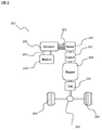
- FIG. 2 is a system block diagram of the hybrid vehicle.
- the present invention is particularly applicable to the rotating electric machine 300 for driving the hybrid vehicle 101.
- the hybrid vehicle 101 shown in FIG. 2 has a parallel drive system capable of transmitting at least one rotational torque to the drive wheels 504 in cooperation with the rotating electrical machine 300 and the fuel injection type engine 500.
- the present invention is not limited to the application to the parallel hybrid vehicle 101.
- the present invention can be widely used for electric vehicles (hybrid vehicles, electric vehicles, fuel cell vehicles) using a rotating electric machine.
- the hybrid vehicle 101 starts running with, for example, the rotational torque of the rotating electrical machine 300 as the main power.
- the clutch 501 is in a connected state.
- the fuel injection engine 500 which is an internal combustion engine, starts. Thereafter, the hybrid vehicle 101 can continue traveling with the rotational torque generated by the fuel injection engine 500 as the main driving force.
- Rotational torque generated by the rotating electrical machine 300 and the fuel injection type engine 500 is transmitted to the drive wheels 504 via the transmission 502 and the differential gear 503.
- the rotating electrical machine 300 may generate rotational torque so as to assist the rotational torque of the fuel injection type engine when high rotational torque is required, such as acceleration or climbing.
- the rotating electrical machine 300 At the time of regenerative braking operation, the rotating electrical machine 300 generates AC power based on the rotational torque transmitted from the drive wheels 504.
- the generated AC power is converted into DC power by the inverter circuit 200 and charged in the power supply source 204.
- the electric power charged in the power supply source 204 is used again as travel energy.
- the inverter circuit 200 is electrically connected to the power supply source 204 via the power cable 205. Then, power is exchanged between the power supply source 204 and the inverter circuit 200. When operating the rotating electrical machine 300 as a motor, the inverter circuit 200 converts the DC power supplied from the power supply source 204 via the power cable 205 into AC power and supplies the AC power to the rotating electrical machine 300.
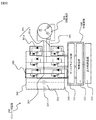
- FIG. 3 is a diagram illustrating a configuration of a drive system for a rotating electrical machine.
- the rotating electrical machine drive system includes an inverter circuit 200, a rotating electrical machine 300, and a control device 400.
- the inverter circuit 200 has, for example, a three-phase AC inverter circuit shown in FIG.
- the inverter circuit 200 includes a power device 201 that applies an N-phase AC voltage to the stator.
- a MOS field effect transistor (MOS-FET) and an insulated gate bipolar transistor (IGBT) are selectively used depending on the withstand voltage and applied voltage. However, this does not exclude the use of other power devices.
- a leg 206 per phase of the inverter circuit 200 includes a power device and a diode (hereinafter referred to as an upper arm power device or power device) 201 a that operates as an upper arm, and a power device and a diode that operates as a lower arm (hereinafter referred to as a lower arm). Arm power device or power device) 201b is connected in series.
- the inverter circuit 200 includes the legs 206 corresponding to the three phases of the U phase, V phase, and W phase of the AC power to be output. These three phases correspond to the three-phase windings of the stator coil 311 of the rotating electrical machine 300 (see FIG. 5).
- Each of the three-phase legs 206 outputs an alternating current from each intermediate electrode 207 to each phase winding of the rotating electrical machine 300 via the power cable 205 or an alternating current bus bar (not shown).
- the terminal on the side not connected to the intermediate electrode 207 of the upper arm power device 201 a is electrically connected to the positive electrode bus 208.
- the terminal on the side not connected to the intermediate electrode 207 of the lower arm power device 201 b is electrically connected to the negative electrode bus 209.
- the positive electrode bus 208 and the negative electrode bus 209 are electrically connected to the smoothing capacitor 210. Further, the positive electrode bus 208 and the negative electrode bus 209 are connected to the power supply source 204 via the power cable 205 and the like.
- the control device 400 includes a gate driver circuit 211 and a control circuit 212. The control device 400 receives a control command from the host control device 213 that determines the operation state of the driver of the vehicle, for example.
- the control circuit 212 includes a control unit (microcomputer, also referred to as a microcomputer) (not shown) for calculating the switching timing of each power device 201.
- the input information to the control unit includes, for example, a target rotational torque value required for the rotating electrical machine 300, a current value supplied from the inverter circuit 200 to the rotating electrical machine 300, a magnetic pole position of the rotor 320 of the rotating electrical machine 300, and the like. There is.
- the control unit calculates U-phase, V-phase, and W-phase voltage command values based on the received control commands and sensed physical values. Then, the control unit generates a pulse-like modulated wave from a comparison between the fundamental wave (sine wave) and the carrier wave (triangular wave) based on the voltage command value of each phase, and the generated modulated wave is PWM (pulse width modulated). ) As a signal to the gate driver circuit 211 (PWM control).
- the gate driver circuit 211 generates a drive pulse for controlling the power device 201 of each phase based on the PWM signal input from the control circuit 212 and supplies the drive pulse to the power device 201 of each phase.
- the power device 201 of each phase performs conduction and cutoff operation based on the drive pulse, converts the DC power supplied from the power supply source 204 into three-phase AC power, and supplies it to each phase of the rotating electrical machine 300.
- FIG. 4 is a diagram illustrating an example of a clamp circuit.
- the clamp circuit 250 is provided in the vicinity of the power device 201.
- the clamp circuit 250 is energized when a voltage equal to or higher than a predetermined voltage is applied between the input terminal 202 and the signal input terminal 203 of the power device 201.
- the clamp circuit 250 has a role of suppressing a surge voltage generated when the power device 201 of the inverter circuit 200 is switched.
- the inverter circuit 200 includes an electromagnetic noise countermeasure filter (abbreviated as Y capacitor) (not shown) of a star-connected capacitor.
- Y capacitor electromagnetic noise countermeasure filter
- the clamp circuit 250 includes a recovery diode 215 and a Zener diode for the clamp circuit.
- the input terminal 202 is connected to the positive electrode bus 208 when the power device 201 is a power device for the upper arm, and is connected to the intermediate electrode 207 arranged at one place for each phase when the power device is the power device for the lower arm. ing.
- the signal input terminal 203 is connected to the gate driver circuit 211.
- the output terminal 214 is connected to the intermediate electrode 207 when the power device 201 is an upper arm power device, and is connected to the negative electrode bus 209 when the power device 201 is a lower arm power device.
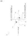
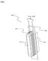
- FIG. 5 is a diagram illustrating an example of a rotating electrical machine.
- the rotating electric machine 300 is a permanent magnet synchronous motor, and a permanent magnet type synchronous motor using a magnet 322 such as neodymium is suitable. However, this does not exclude the use of other rotating electrical machines.
- the present invention can be widely applied to induction motors, reluctance torque motors or generators.
- the rotating electrical machine 300 not only generates rotational torque depending on the operation method, but also has a function of converting mechanical energy applied to the rotating electrical machine 300 from the outside into electric power.
- a rotating electrical machine 300 illustrated in FIG. 5 is, for example, a concentrated winding rotating electrical machine 305. However, this does not exclude winding methods other than concentrated winding.
- the rotating electrical machine 300 includes a stator 310 and a rotor 320.
- the stator 310 is composed of a phase coil of N (N is an integer of 3 or more) phase and has a stator core 313.
- FIG. 6 is a partially enlarged view 306 of FIG. 5, in which one portion of the stator core 313 around which the multiphase stator coil 311 is wound is extracted.
- a multiphase stator coil 311 is wound around the stator core 313 at least once.
- one end 311a is connected to one of the U phase, V phase, and W phase of the inverter device, and the other 311b is the other It is connected to the phase stator coil and grouped as a neutral point (not shown).
- An insulating member 314 is inserted between the stator core 313 and the multiphase stator coil 311.
- the insulating member 314 corresponds to, for example, a resin component or insulating paper.
- the rotor 320 is formed of a rotor core 321, a magnet 322, and a rotation shaft 323.
- the rotor core 312 is made of, for example, a silicon steel plate, and is responsible for fixing the magnet 322 and fastening with the rotating shaft 323.
- the magnet 322 is a permanent magnet, for example, and is a magnet such as a ferrite magnet or neodymium.
- the stator 310 and the rotor 320 are housed in, for example, an aluminum casing and constitute a rotating electric machine.
- the stator 310 and the rotor 320 are fastened to the vehicle body via the aluminum casing.
- the rotating electrical machine 300 is cooled by any one or a combination of an air cooling method, a water cooling method, and an oil cooling method.
- the current input to the power device 201 is a value that exceeds the allowable current value of each power device 201. However, if the duration is extremely short, the durability of the power device 201 is not affected.
- FIG. 7 is an operation progress diagram of the power device 201 when an excessive current is input to the inverter circuit 200 without attaching the clamp circuit 250.
- a surge voltage 263 is generated in the input / output voltage 262 of the power device.
- the magnitude of the surge voltage 263 is proportional to the input current 261 to be cut off. If the surge voltage 263 exceeds the allowable voltage limit 265 of the power device 201, the power device 201 may be damaged.
- the reason why the power device is damaged by the interruption is the electromagnetic energy of the wiring inductance. For example, if the input current limit rating 303 three times larger than the current maximum rating 301, the electromagnetic energy ratio becomes nine times (from Li 2/2 (L is the inductance of the AC bus bar)).
- a loss 266 occurs when the power device is turned off.
- FIG. 8 is an operation progress diagram of the power device 201 when an excessive current is input to the inverter circuit 200 to which the clamp circuit 250 is attached.
- the upper limit of the surge voltage 264 generated in the input / output voltage 262 of the power device 201 is limited by the clamp circuit 250, and thus does not become a voltage that can damage the power device 201.
- the clamp circuit 250 generates a loss 267 as a product of voltage, current, and time. Therefore, the loss 267 of the clamp circuit 250 increases as the duration time increases. And since the power device 201 becomes high temperature by the loss 267, there is a possibility of thermal damage.
- the clamp circuit 250 is used and the carrier wave (carrier frequency) is lowered. This is because the switching loss caused by the carrier wave is smaller when the carrier wave has a lower frequency. From the above, loss 267 can be reduced to loss 268.
- FIG. 9 is a diagram showing that the influence of the surge voltage remains when the clamp circuit is used when the carrier wave has a high frequency.
- the clamp circuit 250 can suppress the loss of the power device 201 and prevent the damage by suppressing the excessive increase in the voltage 262 between the input and output of the power device and suppressing the switching loss at a low carrier frequency.
- the control unit performs control to lower the frequency of PWM control in the energized state than the frequency of PWM control before the energized state.
- the present invention can be applied to all rotating electrical machine drive systems in which the inverter circuit 200 using a carrier wave and the rotating electrical machine 300 are combined.
- FIG. 11 is a flowchart for explaining control for executing or canceling the lowering of the carrier frequency.
- a sequence for lowering the PWM control frequency in the energized state than the PWM control frequency before the energized state is defined as an on sequence, and the PWM control frequency is defined as the clamp circuit frequency.
- a sequence that approaches the frequency of PWM control before the energized state is defined as an off sequence.
- the on-sequence 271 for lowering the carrier frequency is as follows. Each process switching determination is performed by the control unit, but may be configured using a logic circuit.
- the control unit detects the excessive current based on the result sensed by a current sensor (not shown), for example (272).
- a current sensor not shown
- the clamp circuit 250 is automatically activated.
- the operation start of the clamp circuit 250 cannot be detected by the control unit. Therefore, a circuit for causing the control unit to detect the operation of the clamp circuit 250 is necessary.
- the circuit 252 illustrated in FIG. 12 is an operation determination circuit of the clamp circuit 250.
- a logic circuit is assembled so as to satisfy the truth table 254 from both-end signals of the buffer circuit 253 provided in the signal input terminal 203 of the power device 201.
- A becomes Low and B becomes High.
- the logic circuit is set so that C is High under this condition.
- the result of C is taken into the control unit via, for example, a D / A converter (not shown). Then, the control unit determines that the clamp circuit 250 is operating (273). This establishes an on-sequence for lowering the frequency of the carrier wave (274).
- the control unit detects the temperature of the power device 201 (276).
- the temperature of the power device 201 is the measured temperature or the estimated temperature.
- the estimated temperature corresponds to a value calculated by, for example, a heat estimation model or an observer.
- the control unit compares the detected temperature with a predetermined temperature (for example, a value obtained by subtracting the likelihood from the maximum operating temperature of the control unit).
- the control unit determines whether the frequency of the PWM control is close to the frequency of the PWM control before the clamp circuit 250 is energized based on the temperature information of the power device 201.
- the control unit reduces the energization current to the power device 201 by limiting the current to protect the power device 201. Then, the control unit warns the driver of an overheat signal. And it changes to the carrier frequency at the time of the normal control determined according to the rotation speed of the rotary electric machine 300 (278).
- the control unit does not change to the carrier frequency during normal control until the activation condition of the off sequence 275 is established in advance. Then, when the condition is satisfied, a carrier frequency (carrier frequency during normal control) based on the current rotational speed of the rotating electrical machine is calculated and returned to the calculated carrier frequency.
- Condition example 1 is a method using the operation determination circuit 252 of the clamp circuit. First, the control unit confirms that the clamp circuit 250 is off. It is determined from the following method that the clamp circuit 250 is not operating. When the C column in the truth table 254 becomes Low, it is determined that the clamp circuit 250 is not operating.
- the control unit calculates the carrier frequency based on the current rotational speed of the rotating electrical machine 300. Then, the control unit changes to the calculated carrier frequency and shifts to normal control (278). If the condition is not satisfied, the process continues until the condition is satisfied.
- Condition example 2 is a method using the operation determination circuit 252 of the clamp circuit.
- the difference from Condition Example 1 is a determination method for determining that the clamp circuit 250 is not operating.
- the control unit detects a current input to the rotating electrical machine 300.
- the control unit compares the detected current with the maximum rated current 301. If the detected current is smaller than the maximum rated current 301, it is determined that the clamp circuit 250 is not operating. If it is determined that the clamp circuit is not operating, it is determined that the condition is satisfied (277).
- the control unit calculates the carrier frequency based on the current rotational speed of the rotating electrical machine 300. Then, the control unit changes to the calculated carrier frequency and shifts to normal control (278). If the condition is not satisfied, the process continues until the condition is satisfied.
- a hysteresis comparator may be used for comparison judgment.
- Condition Example 3 is a method using a timer.
- the timer is incorporated in the control unit as a program.
- the timer starts counting for a maximum of N seconds from the moment when the operation of the clamp circuit 250 is detected or the moment when the carrier wave is changed to a low frequency (N is a value of 0 or more).
- the control unit determines whether the frequency of the PWM control is close to the frequency of the PWM control before the energized state of the clamp circuit 250 based on the elapsed time from the start point of the energized state of the clamp circuit 250. For example, when N seconds elapse, the control unit redetects the temperature of the power device 291. If the power device temperature is equal to or higher than the predetermined temperature, it is determined that the condition is satisfied (277). When the condition is satisfied, the control unit calculates the carrier frequency based on the current rotational speed of the rotating electrical machine 300. Then, the control unit changes to the calculated carrier frequency and shifts to normal control (278). When the condition is not satisfied, the timer again counts N seconds from the moment when it is determined that the condition is not satisfied. When N seconds have elapsed, the control unit performs the same detection and comparison as described above.
- Example 4 is a method using a no-load induced voltage. For example, it is assumed that the application of the limit rating region 302 is assisting the rotational torque of the fuel injection engine 500 at the initial start. In this case, after the initial startup period of the fuel injection engine 500 has passed, the rotational torque assist by the rotating electrical machine 300 is unnecessary.
- the control unit can detect the no-load induced voltage from the terminals (not shown) of each phase of the rotating electrical machine 300.
- the control unit determines from the no-load induced voltage whether the rotational speed of the fuel injection type engine 500 is equal to or higher than the rotational speed at which the fuel injection engine 500 can be driven stably. Alternatively, the rotational speed of the fuel injection engine 500 may be directly detected and determined.
- the control unit determines whether the frequency of the PWM control is brought close to the frequency of the PWM control before the clamp circuit 250 is energized based on the rotational speed of at least one of the rotating electrical machine 300 or the fuel injection type engine 500.
- the control unit determines that the condition is satisfied when the rotational speed is equal to or higher than the fuel injection type engine 500 that can be driven stably (277).
- the control unit calculates the carrier frequency based on the current rotational speed of the rotating electrical machine 300. Then, the calculated carrier frequency is changed to the normal control (278). If the condition is not satisfied, the process continues until the condition is satisfied.
- FIG. 13 is a flowchart showing a process of responding to the output of high rotational torque while executing the application judgment of the present invention.
- control unit When the control unit detects a high rotational torque request, it calculates a necessary rotational torque command value (281). Then, it is determined whether the calculated rotational torque command value is in the limit rated region 302 (282). If the rotational torque command value is less than or equal to the maximum rating of 301, the high rotational torque request is met without applying the present invention.
- the control unit determines whether low carrier frequency control is applied (283). This determination is made from the current carrier frequency or the operation determination circuit 252 of the clamp circuit. When the low carrier frequency control is not applied, the ON sequence 271 of FIG. 11 is promptly executed (284).
- the control unit After the low carrier frequency control is applied, the control unit performs execution determination of the off sequence 275 in FIG. 11 (285).
- the process immediately proceeds to the off sequence 275. Thereby, an excessive temperature rise of the power device 201 can be prevented.
- the off sequence 275 When the off sequence 275 is not executed immediately, it responds to the high rotational torque request as it is.
- the control unit continues the off sequence 275 when the condition of the on sequence 271 is satisfied while the off sequence 275 is being executed (285) (286).
- the normal control is immediately performed. At this time, if the off sequence 275 is not executed, the off sequence 275 is executed and then the normal control is performed.
- the power device of the inverter circuit can be appropriately protected from heat and surge voltage generated when an excessive current is applied from the inverter circuit to the rotating electrical machine.
- the present invention is not limited to the above-described embodiments, and various designs can be made without departing from the spirit of the present invention described in the claims. It can be changed.
- the above-described embodiment has been described in detail for easy understanding of the present invention, and is not necessarily limited to one having all the configurations described.
- a part of the configuration of an embodiment can be replaced with the configuration of another embodiment, and the configuration of another embodiment can be added to the configuration of an embodiment.
- Clamp circuit 251 Zener diode for clamp circuit 252
- Clamp circuit operation determination circuit 253 Buffer circuit 254.
- Current 262 ... Voltage between input and output of power device 263 ... Surge voltage (without clamp circuit) 264 ... Surge voltage (without clamp circuit) 265: Allowable voltage limit of power device 266: Loss of power device (without clamp circuit) 267 ... Power device loss (with clamp circuit) 268 ... Power device loss (Clamp circuit and low carrier frequency applied) 271 ... ON sequence 272 ... Overcurrent detection sequence 273 ... Clamp circuit operation determination sequence 274 ... Sequence for lowering carrier frequency 275 ... Off sequence 276 ... Power device temperature Detection sequence 277 ... off sequence activation condition check sequence 278 ...
Landscapes
- Engineering & Computer Science (AREA)
- Power Engineering (AREA)
- Transportation (AREA)
- Mechanical Engineering (AREA)
- Electric Propulsion And Braking For Vehicles (AREA)
- Inverter Devices (AREA)
- Hybrid Electric Vehicles (AREA)
- Control Of Ac Motors In General (AREA)
- Control Of Motors That Do Not Use Commutators (AREA)
Abstract
インバータ回路から回転電機に過大電流を印加したときにインバータ回路のパワーデバイスを適切に保護することができる回転電機駆動システムの制御装置を得ること。 回転電機駆動システム100の制御装置400は、N(Nは3以上の整数)相の相コイルにより構成される固定子310を有する回転電機300と、固定子310にN相の交流電圧を印加するパワーデバイス201を有するインバータ回路200を備え、パワーデバイス201をPWM制御する制御部を有する。インバータ回路200は、パワーデバイス201の入力端子202と信号入力端子203との間に所定電圧以上の電圧が印加されると通電するクランプ回路250を有している。そして、制御部は、クランプ回路250が通電状態となった場合、通電状態前のPWM制御の周波数よりも通電状態のPWM制御の周波数を低くする。
Description
本発明は、インバータ回路により回転電機を制御する回転電機駆動システムの制御装置に関する。
ハイブリッド自動車や電気自動車、燃料電池自動車等の電動車両は、駆動用の回転電機を有しており、かかる回転電機に対する低電圧化と小型高出力化の要求が高まっている。
一般的に、回転電機に印加される通常電流は、固定子コイルの電流密度と発熱量、固定子コアや回転子コアの磁気飽和、インバータ回路のパワーデバイスの容量と発熱許容量など、主に発熱量とその安全率と許容できる継続時間を考慮して、予め設定された最大定格に制限されている。そして、最大定格を超えた過大電流をインバータ回路から回転電機に一時的に印加して、回転トルクを増大させることが行われている。
一般的に、回転電機に印加される通常電流は、固定子コイルの電流密度と発熱量、固定子コアや回転子コアの磁気飽和、インバータ回路のパワーデバイスの容量と発熱許容量など、主に発熱量とその安全率と許容できる継続時間を考慮して、予め設定された最大定格に制限されている。そして、最大定格を超えた過大電流をインバータ回路から回転電機に一時的に印加して、回転トルクを増大させることが行われている。
特許文献1には、正弦波駆動の最大定格よりも大きな回転トルクの発生を要求する大トルク発生指令を受けたときに、非正弦波駆動モードに移行して回転電機の回転トルクを増加させる制御技術が示されている。
インバータ回路から回転電機に過大電流を印加したときに発生する熱やサージ電圧からインバータ回路のパワーデバイスを適切に保護する必要がある。
本発明は、上記の点に鑑みてなされたものであり、その目的とするところは、インバータ回路から回転電機に過大電流を印加したときにインバータ回路のパワーデバイスを適切に保護することができる回転電機駆動システムの制御装置を提供することである。
本発明は、上記の点に鑑みてなされたものであり、その目的とするところは、インバータ回路から回転電機に過大電流を印加したときにインバータ回路のパワーデバイスを適切に保護することができる回転電機駆動システムの制御装置を提供することである。
上記課題を解決する本発明の回転電機駆動システムの制御装置は、N(Nは3以上の整数)相の相コイルにより構成される固定子を有する回転電機と、前記固定子にN相の交流電圧を印加するパワーデバイスを有するインバータ回路と、を備える回転電機駆動システムの制御装置であって、前記パワーデバイスをPWM制御する制御部を有し、インバータ回路は、パワーデバイスの入力端子と当該パワーデバイスのゲート端子との間に所定電圧以上の電圧が印加されると通電するクランプ回路を有し、前記制御部は、前記クランプ回路が通電状態となった場合、当該通電状態前の前記PWM制御の周波数よりも当該通電状態の当該PWM制御の周波数を低くすることを特徴とする。
本発明によれば、インバータ回路から回転電機に過大電流を印加したときに発生する熱やサージ電圧からインバータ回路のパワーデバイスを適切に保護することができる。なお、上記した以外の課題、構成及び効果は、以下の実施形態の説明により明らかにされる。
図1は、高出力化のために回転トルクを増加した場合の3相交流回転電機の出力線図である。3相交流回転電機の回転トルクを増加させる方法は、磁石の増量と電流の増加の2方法があるが、磁石増量をさせる方法は避けたい。これは、低電圧化要求の観点から、駆動中の誘起電圧の増加を回避したいからである。そのため、インバータ回路から回転電機に供給する電流を増加させて、トルクを増大させる方法を採用する。
一般的には、回転電機300の回転トルクは、図1に実線で示されるように、最大定格301に制限される。制限を左右している要因は、回転電機300の固定子コイル311の電流密度と発熱量、固定子コア312や回転子コア321の磁気飽和、インバータ回路200のパワーデバイス201の容量と発熱許容量など、主に発熱量とその安全率と許容できる継続時間である。
この最大定格301を超えて、図1に示した限界定格領域302の限界定格303を得るためには、過大電流の印加が必要になる。限界定格領域302は、主に車両発進時の補助用途が予想される。その理由は、通常加速時に使用すると、強すぎる回転トルクが発生する危険性があるからである。そのため、限界定格領域302の使用継続時間は、発進直後の数秒間を主要使用範囲と想定している。
そして、過大電流を印加したときに発生する熱に対するインバータ回路200のパワーデバイス201の発熱対策と保護方法が,大きな課題である。すなわち、本発明の課題は、過大電流入力時のパワーデバイス201の発熱対策と保護方法である
図2は、ハイブリッド自動車のシステムブロック図である。
本発明は、特にハイブリッド自動車101の駆動用の回転電機300に適用できる発明である。
本発明は、特にハイブリッド自動車101の駆動用の回転電機300に適用できる発明である。
図2に示すハイブリッド自動車101は、回転電機300と燃料噴射型エンジン500との協調により、少なくとも一方の回転トルクを駆動輪504に伝達可能なパラレル方式の駆動系を有している。ただし、本発明はパラレル方式のハイブリッド自動車101への適用に限定するものではない。本発明は、回転電機を用いる電動車両(ハイブリッド自動車,電気自動車, 燃料電池自動車)に幅広く使用できる。
ハイブリッド自動車101は、例えば回転電機300の回転トルクを主動力として走行を開始する。このとき、クラッチ501は接続状態にある。そして、車速が早くなると、内燃機関である燃料噴射型エンジン500が始動する。その後、ハイブリッド自動車101は、燃料噴射型エンジン500が発生した回転トルクを主駆動力として走行を継続することができる。
回転電機300や燃料噴射型エンジン500が発生させた回転トルクは,トランスミッション502とディファレンシャルギア503を介して,駆動輪504に伝達される。回転電機300は、加速や登坂など、高回転トルクが必要なときに、燃料噴射型エンジンの回転トルクをアシストするように回転トルクを発生させることがある。
回生制動の運転時、回転電機300は、駆動輪504から伝達されてきた回転トルクに基づいて、交流電力を発生する。発生した交流電力は、インバータ回路200により直流電力に変換されて、電力供給源204に充電される。そして、電力供給源204に充電された電力は、走行エネルギーとして再び使用される。
インバータ回路200は、パワーケーブル205を介して電力供給源204と電気的に接続されている。そして、電力供給源204とインバータ回路200との相互において電力の授受が行われる。回転電機300をモータとして動作させる場合、インバータ回路200は、パワーケーブル205を介して電力供給源204から供給された直流電力を交流電力に変換し、回転電機300に供給する。
図3は、回転電機の駆動システムの構成を説明する図である。
回転電機駆動システムは、インバータ回路200と、回転電機300と、制御装置400を有している。インバータ回路200は、例えば図3に示す3相交流のインバータ回路を有している。
回転電機駆動システムは、インバータ回路200と、回転電機300と、制御装置400を有している。インバータ回路200は、例えば図3に示す3相交流のインバータ回路を有している。
インバータ回路200は、固定子にN相の交流電圧を印加するパワーデバイス201を有する。インバータ回路200に使用されるパワーデバイス201は、耐圧や印加電圧によって、MOS型電界効果トランジスタ(MOS-FET) と絶縁ゲート型バイポーラトランジスタ(IGBT)が使い分けられる。ただし、これは他のパワーデバイスの使用を除外するものではない。
インバータ回路200の1相あたりのレグ206は、上アームとして動作するパワーデバイス及びダイオード(以下、上アーム用パワーデバイス、またはパワーデバイス) 201aと、下アームとして動作するパワーデバイス及びダイオード(以下、下アーム用パワーデバイス、またはパワーデバイス)201bの直列接続で構成されている。
インバータ回路200は、このレグ206を、出力しようとする交流電力のU相、V相、W相の三相にそれぞれ対応して備えている。これらの三相は、回転電機300の固定子コイル311の三相の各相巻線に対応している(図5を参照)。
三相のそれぞれのレグ206は、それぞれの中間電極207からパワーケーブル205または交流バスバ(不図示)を介して、回転電機300の各相巻線に交流電流を出力する。上アーム用パワーデバイス201aの中間電極207につながれていない側の端子は、正極バス208に電気的に接続されている。下アーム用パワーデバイス201bの中間電極207につながれていない側の端子は、負極バス209に電気的に接続されている。
正極バス208と負極バス209は、平滑用コンデンサ210に電気的に接続されている。さらに、正極バス208と負極バス209は、パワーケーブル205などを介して、電力供給源204に接続されている。制御装置400は、ゲートドライバ回路211と制御回路212から構成されている。制御装置400は、たとえば車両の運転手の操作状態を判断する上位制御装置213から制御指令を受ける。
制御回路212は、各パワーデバイス201のスイッチングタイミングを演算処理するための制御部(マイクロコンピュータ。別称、マイコン)(不図示)を備えている。制御部への入力情報は、例えば、回転電機300に対して要求される目標回転トルク値、インバータ回路200から回転電機300に供給される電流値、及び回転電機300の回転子320の磁極位置などがある。
制御部は、受けた制御指令やセンシングされた物理値に基づいて、U相、V相、W相の電圧指令値を演算する。そして、制御部は、各相の電圧指令値に基づく基本波(正弦波)と搬送波(三角波)との比較からパルス状の変調波を生成し、この生成された変調波をPWM(パルス幅変調)信号としてゲートドライバ回路211に出力する(PWM制御)。
ゲートドライバ回路211は、制御回路212から入力したPWM信号に基づいて各相のパワーデバイス201を制御するための駆動パルスを生成し、各相のパワーデバイス201に供給する。
各相のパワーデバイス201は、駆動パルスに基づいて、導通と遮断動作を行い、電力供給源204から供給された直流電力を三相交流電力に変換し、回転電機300の各相に供給する。
図4は、クランプ回路の一例を示す図である。
クランプ回路250は、パワーデバイス201の近傍に備え付けられている。クランプ回路250は、パワーデバイス201の入力端子202と信号入力端子203との間に所定電圧以上の電圧が印加されると通電する。クランプ回路250は、インバータ回路200のパワーデバイス201がスイッチングする時に発生するサージ電圧を抑制する役割を持つ。上記以外にもインバータ回路200は、スター結線されたコンデンサの電磁ノイズ対策用フィルタ(Yコンデンサと略称する)(不図示)を備える。
クランプ回路250は、パワーデバイス201の近傍に備え付けられている。クランプ回路250は、パワーデバイス201の入力端子202と信号入力端子203との間に所定電圧以上の電圧が印加されると通電する。クランプ回路250は、インバータ回路200のパワーデバイス201がスイッチングする時に発生するサージ電圧を抑制する役割を持つ。上記以外にもインバータ回路200は、スター結線されたコンデンサの電磁ノイズ対策用フィルタ(Yコンデンサと略称する)(不図示)を備える。
クランプ回路250は、リカバリダイオード215と、クランプ回路用のツェナーダイオードを有している。そして、入力端子202は、パワーデバイス201が上アーム用パワーデバイスの場合は正極バス208に接続され、下アーム用パワーデバイスの場合は各相に1ヶ所ずつ配置されている中間電極207に接続されている。信号入力端子203は、ゲートドライバ回路211に接続されている。出力端子214は、パワーデバイス201が上アーム用パワーデバイスの場合は中間電極207に接続され、下アーム用パワーデバイスの場合は負極バス209に接続されている。
図5は、回転電機の一例を示す図である。
回転電機300は、永久磁石同期電動機であり、ネオジウムなどの磁石322を使用した永久磁石型の同期電動機が適している。ただし、これは、他の回転電機の使用を除外するものではない。
回転電機300は、永久磁石同期電動機であり、ネオジウムなどの磁石322を使用した永久磁石型の同期電動機が適している。ただし、これは、他の回転電機の使用を除外するものではない。
本発明は、誘導電動機やリラクタンストルク電動機または発電機などに幅広く応用できる。回転電機300は、運転方法により回転トルクを発生するだけでなく、回転電機300に外部から加えられる機械エネルギーを電力に変換する機能を有する。
図5に示す回転電機300は、例えば集中巻型回転電機305である。ただし、これは、集中巻以外の巻線方式を除外するものではない。回転電機300は、固定子310と回転子320を有する。固定子310は、N(Nは3以上の整数)相の相コイルにより構成され
ており、固定子鉄心313を有する。
ており、固定子鉄心313を有する。
図6は、図5の部分拡大図306であり、多相固定子コイル311が捲回された固定子鉄心313の1本分を抜き出した図である。固定子鉄心313には、多相固定子コイル311が1回以上捲回されている。固定子鉄心313に複数回捲回された多相固定子コイル311において、その終端の一方311aはインバータ装置のU相、V相、W相のいずれかに接続されており、他方311bは、他相の固定子コイルと接続されて、中性点としてまとめられている(不図示)。固定子鉄心313と多相固定子コイル311の間には,絶縁部材314が挿入されている。絶縁部材314は、例えば、樹脂系部品や絶縁紙が相当する。
回転子320は、回転子コア321、磁石322、回転軸323から形成されている。回転子コア312は、例えばケイ素鋼板製で、磁石322の固定や回転軸323との締結を担う。磁石322は、たとえば永久磁石であり、フェライト磁石やネオジウムなどの磁石である。
固定子310と回転子320は、例えばアルミ製筐体などに収納されており、回転電機を構成している。固定子310と回転子320は、そのアルミ製筐体を介して自動車の車体に締結される。回転電機300は、空冷方式、水冷方式、油冷方式のいずれかまたは併用によって冷却される。
図1に示す限界定格領域302においてパワーデバイス201に入力される電流は、各パワーデバイス201の許容電流値を超過した値である。しかし、継続時間が、極短時間であればパワーデバイス201の耐久性に影響を与えることはない。
図7は、クランプ回路250を取り付けずに、インバータ回路200に過大電流を入力したときのパワーデバイス201の動作経過図である。
一般的に、パワーデバイス201に電流が入力されている時にスイッチングオフ(パワーデバイスオフ)になると、パワーデバイスの入出力間電圧262にサージ電圧263が発生する。サージ電圧263の大きさは、遮断する入力電流261に比例する。サージ電圧263が、パワーデバイス201の許容電圧限界265を超過すると、パワーデバイス201が破損するおそれがある。
遮断によってパワーデバイスが破損する理由は、配線インダクタンスの電磁エネルギーである。例えば、限界定格303の入力電流が最大定格301の電流に対して3倍大きい場合、電磁エネルギー比は、9倍になる(Li2/2より(Lは交流バスバのインダクタンス))。
図7に示すように、パワーデバイスのオフによって損失266は発生するが、短時間または、パワーデバイス201の破損の可能性から重要視されない。
図8は、クランプ回路250を取り付けたインバータ回路200に過大電流を入力したときの、パワーデバイス201の動作経過図である。
パワーデバイス201の入出力間電圧262に発生したサージ電圧264は、クランプ回路250によって上限を制限されるため、パワーデバイス201を破損させるほどの電圧にはならない。
なお、クランプ回路250は、電圧と電流と時間の積で損失267を発生させる。したがって、クランプ回路250の損失267は、継続時間が長いほど大きくなる。そして、その損失267によってパワーデバイス201が高温化するため、熱破損する可能性がある。
そこで、損失267を下げるために、クランプ回路250を用いるとともに、搬送波(キャリア周波数)を低周波化させる。搬送波によって発生するスイッチング損失は、搬送波が低周波数のほうが小さいからである。以上より、損失267を損失268まで低減させることができる。
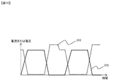
図9は、搬送波が高周波であるときにクランプ回路を用いた場合のサージ電圧の影響の残存することを示した図である。
クランプ回路250を適用すると、パワーデバイス201が完全にオフになる時間が延びる。そのため、図9のように、搬送波が高周波のままでは、回転電機300が高回転であるほど、一回前のスイッチング時にクランプ回路250が抑制したサージ電圧264の影響が残る可能性がある。
しかし、搬送波が低周波であれば、図10のように、クランプ回路250が抑制したサージ電圧264の影響を最小限にできる時間を得られる。これによって、クランプ回路250は、パワーデバイスの入出力間電圧262の過上昇を抑制し、低キャリア周波数化でスイッチング損失を抑制することで、パワーデバイス201の損失最小化と破損阻止ができる。制御部は、クランプ回路250が通電状態となった場合、通電状態前のPWM制御の周波数よりも通電状態のPWM制御の周波数を低くする制御を行う。
本発明は、搬送波を利用しているインバータ回路200と、回転電機300を組み合わせた回転電機駆動システム全てに適用できる。
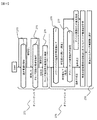
図11は、キャリア周波数の低周波数化を実行又は解除する制御を説明するフローチャートである。以下では、クランプ回路250が通電状態となった場合、通電状態前のPWM制御の周波数よりも通電状態のPWM制御の周波数を低くするシーケンスをオンシーケンスと定義し、PWM制御の周波数をクランプ回路の通電状態前のPWM制御の周波数に近づけるシーケンスをオフシーケンスと定義する。
このプロセスは、回転電機300に過大電流が印加された場合にのみ適用される。領域を限定する理由は、低キャリア周波数は、回転電機300の振動騒音特性を悪化させる要因になるからである。キャリア周波数を低周波化するオンシーケンス271は、次の通りである。なお、各プロセス切替判断は、制御部で行われるが、論理回路を使って構成しても良い。
制御部は、過大電流が回転電機300に印加されると、たとえば、電流センサ(不図示)でセンシングされた結果により、過大電流を検知する(272)。スイッチング動作によって変動するパワーデバイスの入出力間電圧262があらかじめ定められた閾値を超過すると、クランプ回路250が自動的に作動する。
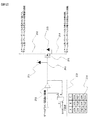
しかし、このクランプ回路250の動作開始は、制御部では検知できない。そのため、クランプ回路250の動作を制御部に検知させる回路が必要である。例えば、図12に示す回路252が、クランプ回路250の動作判定回路である。
同回路は、パワーデバイス201の信号入力端子203に備えられているバッファ回路253の両端信号から、真理値表254を満たすように論理回路が組まれている。クランプ回路250が動作しているとき、AはLow、BはHighになる。論理回路は、この条件のときにCがHighになるように組まれている。Cの結果は、例えばD/Aコンバータ(不図示)を介して、制御部に取り込まれる。そして、制御部は、クランプ回路250が動作中であると判断する(273)。これによって、搬送波を低周波化させるオンシーケンスが成立する(274) 。
次に、オフシーケンス275の発動条件について具体的に説明する。
まず、制御部は、パワーデバイス201の温度を検知する(276)。パワーデバイス201の温度は、実測温度または推定温度とする。推定温度は、例えば熱推定モデルやオブザーバで算出された値が該当する。制御部は、検知した温度を、所定の温度(例えば、制御部の最大作動温度から尤度を減算した値)と比較する。
まず、制御部は、パワーデバイス201の温度を検知する(276)。パワーデバイス201の温度は、実測温度または推定温度とする。推定温度は、例えば熱推定モデルやオブザーバで算出された値が該当する。制御部は、検知した温度を、所定の温度(例えば、制御部の最大作動温度から尤度を減算した値)と比較する。
制御部は、パワーデバイス201の温度情報に基づいて、PWM制御の周波数を、クランプ回路250の通電状態前のPWM制御の周波数に近づけるか否かを判断する。制御部は、パワーデバイス温度が所定温度よりも高い場合、パワーデバイス201の保護のために,電流制限をかけてパワーデバイス201への通電電流を低下させる。そして、制御部は、ドライバーにオーバーヒートシグナルを警告する。そして、回転電機300の回転数に応じて決定される通常制御時のキャリア周波数に変更する(278)。
パワーデバイス201の温度が所定温度よりも低い場合は、出来る限り長時間,限界定格領域302の回転トルクを出力し続けるようにする。そのため、制御部は、あらかじめオフシーケンス275の発動条件が成立するまで、通常制御時のキャリア周波数に変更しない。そして、条件成立により、現在の回転電機の回転数に基づいたキャリア周波数(通常制御時のキャリア周波数)を計算し、その計算されたキャリア周波数に戻す。
オフシーケンス275の発動条件の例を、以下に4点示す。
<条件1>
条件例1は、クランプ回路の動作判定回路252を利用する方法である。
まず制御部は、クランプ回路250のオフを確認する。クランプ回路250が作動していないことは、以下の方法から判断する。真理値表254でC列がLowになったら、クランプ回路250が動作していないと判断する。
条件例1は、クランプ回路の動作判定回路252を利用する方法である。
まず制御部は、クランプ回路250のオフを確認する。クランプ回路250が作動していないことは、以下の方法から判断する。真理値表254でC列がLowになったら、クランプ回路250が動作していないと判断する。
クランプ回路が動作していないことを判断したら、条件成立と判断する(277)。条件成立の場合、制御部は、現在の回転電機300の回転数に基づいてキャリア周波数を計算する。そして、制御部は、その計算したキャリア周波数に変更し、通常制御へと移行する (278)。条件不成立の場合は、条件成立まで継続する。
<条件2>
条件例2は、クランプ回路の動作判定回路252を利用する方法である。
条件例1との差異は、クランプ回路250が作動していないことを判断する判断方法である。
条件例2は、クランプ回路の動作判定回路252を利用する方法である。
条件例1との差異は、クランプ回路250が作動していないことを判断する判断方法である。
まず、制御部は、回転電機300に入力される電流を検知する。制御部は、検知した電流と最大定格301の電流を比較する。検知した電流が最大定格301の電流よりも小さい場合は、クランプ回路250が動作していないと判断する。クランプ回路が動作していないことを判定したら、条件成立と判断する(277)。条件成立の場合、制御部は、現在の回転電機300の回転数に基づいてキャリア周波数を計算する。そして制御部は、その計算したキャリア周波数に変更し、通常制御へと移行する(278)。条件不成立の場合は、条件成立まで継続する。記述はしていないが、比較判断においては、ヒステリシスコンパレータを用いてもよい。
<条件3>
条件例3は、タイマを用いる方法である。
タイマは例えば、制御部にプログラムとして組み込まれている。タイマは、クランプ回路250の動作を検知した瞬間、または搬送波が低周波に変更された瞬間から、最大N秒のカウントを始める(Nは0以上の値)。
条件例3は、タイマを用いる方法である。
タイマは例えば、制御部にプログラムとして組み込まれている。タイマは、クランプ回路250の動作を検知した瞬間、または搬送波が低周波に変更された瞬間から、最大N秒のカウントを始める(Nは0以上の値)。
制御部は、クランプ回路250の通電状態の開始時点からの経過時間に基づいて、PWM制御の周波数を、クランプ回路250の通電状態前のPWM制御の周波数に近づけるか否かを判断する。例えば、N秒が経過したら、制御部は、パワーデバイス291の温度を再検知する。パワーデバイス温度が所定温度以上の場合は、条件成立と判断する(277)。条件成立の場合、制御部は、現在の回転電機300の回転数に基づいてキャリア周波数を計算する。そして、制御部は、その計算したキャリア周波数に変更し、通常制御へと移行する(278)。条件不成立の場合、タイマは不成立と判断された瞬間から、再びN秒をカウントする。制御部は、N秒が経過したら、前記と同様の検知と比較を行う。
<その4>
条件例4は、無負荷誘起電圧を使う方法である。
例えば、限界定格領域302の用途を、初期始動時の燃料噴射型エンジン500の回転トルクのアシストと想定する。この場合、燃料噴射型エンジン500の初期始動期間が過ぎれば、回転電機300による回転トルクのアシストは、不要である。
条件例4は、無負荷誘起電圧を使う方法である。
例えば、限界定格領域302の用途を、初期始動時の燃料噴射型エンジン500の回転トルクのアシストと想定する。この場合、燃料噴射型エンジン500の初期始動期間が過ぎれば、回転電機300による回転トルクのアシストは、不要である。
回転電機300に力行指令がなく、かつ燃料噴射型エンジン500に外部から回転させられている状態にある場合は、無負荷駆動である。したがって、制御部は、回転電機300の各相の端子(不図示)から無負荷誘起電圧を検知できる。制御部は、無負荷誘起電圧から、燃料噴射型エンジン500の回転数が安定して駆動できる回転数以上であるか、回転電機300の回転数から判断する。また、燃料噴射型エンジン500の回転数を直接検知して判断してもよい。
制御部は、回転電機300または燃料噴射型エンジン500の少なくとも一方の回転数に基づいて、PWM制御の周波数を、クランプ回路250の通電状態前のPWM制御の周波数に近づけるか否かを判断する。制御部は、燃料噴射型エンジン500が安定して駆動できる回転数以上の場合、条件成立と判断する(277)。条件成立の場合、制御部は、現在の回転電機300の回転数に基づいてキャリア周波数を計算する。そして、その計算したキャリア周波数に変更し、通常制御へと移行する(278)。条件不成立の場合は、条件成立まで継続する。
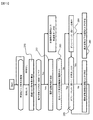
図13は、本発明の適用判断を実施しながら、高回転トルクの出力に応答するプロセスを示したフローチャート図である。
ドライバーから連続して高回転トルク要求が来る可能性がある。連続する高回転トルクの出力要求の状況下において、2回目以降はパワーデバイス201がすでに高温に達している可能性がある。
制御部は、高回転トルク要求を検知したら、必要な回転トルク指令値を算出する(281)。そして、算出された回転トルク指令値が、限界定格領域302にあるか判断する(282)。回転トルク指令値が最大定格301以下であれば、本発明の適用なしで高回転トルク要求に対応する。
一方で、回転トルク指令値が最大定格301よりも高い場合は、限界定格領域302内の回転トルクを要求されたと判断する。次に、制御部は、低キャリア周波数制御が適用されているかを判断する(283)。この判断は、現時点での搬送波周波数、またはクランプ回路の動作判定回路252から行う。低キャリア周波数制御が適用されていないときは、図11のオンシーケンス271を速やかに実行する(284)。
制御部は、低キャリア周波数制御が適用された状態になった後、図11のオフシーケンス275の実行判定を行う(285)。すでにパワーデバイス201が高温であるときは、すぐにオフシーケンス275に移行する。これによって、パワーデバイス201の過剰な温度上昇を防止できる。オフシーケンス275がすぐに実行されない場合は、そのまま高回転トルク要求に対応する。
オフシーケンス275が実行されて、搬送波が高周波化された後も、ドライバーからの高回転トルク要求が継続している場合は、パワーデバイス201の温度を検知しながら、最大定格301以下の回転トルクで対応する(286)。すなわち、制御部は、オフシーケンス275を実行中に(285)、オンシーケンス271の条件を満たした場合に、オフシーケンス275を継続する(286)。
高回転トルク要求が終了した場合は、本プロセスのいずれかを実行中であっても、速やかに通常制御へ移行する。この時、オフシーケンス275が実行されていなければ、オフシーケンス275を実行してから通常制御へ移行する。
上記した回転電機駆動システムの制御装置によれば、インバータ回路から回転電機に過大電流を印加したときに発生する熱やサージ電圧からインバータ回路のパワーデバイスを適切に保護することができる。
以上、本発明の実施形態について詳述したが、本発明は、前記の実施形態に限定されるものではなく、特許請求の範囲に記載された本発明の精神を逸脱しない範囲で、種々の設計変更を行うことができるものである。例えば、前記した実施の形態は本発明を分かりやすく説明するために詳細に説明したものであり、必ずしも説明した全ての構成を備えるものに限定されるものではない。また、ある実施形態の構成の一部を他の実施形態の構成に置き換えることが可能であり、また、ある実施形態の構成に他の実施形態の構成を加えることも可能である。さらに、各実施形態の構成の一部について、他の構成の追加・削除・置換をすることが可能である。
100・・・回転電機駆動システム
101・・・ハイブリッド自動車
200・・・インバータ回路
201・・・パワーデバイス
201a・・・上アームとして動作するパワーデバイス及びダイオード
201b・・・下アームとして動作するパワーデバイス及びダイオード
202・・・パワーデバイスの入力端子
203・・・パワーデバイスの信号入力端子203
204・・・電力供給源
205・・・パワーケーブル
206・・・1相あたりのレグ
207・・・中間電極(各相に1ヶ所ずつ)
208・・・正極バス
209・・・負極バス
210・・・平滑用コンデンサ
211・・・ゲートドライバ回路
212・・・制御回路
213・・・上位制御装置
214・・・パワーデバイスの出力端子
215・・・リカバリダイオード
250・・・クランプ回路
251・・・クランプ回路用ツェナーダイオード
252・・・クランプ回路の動作判定回路
253・・・バッファ回路
254・・・真理値表
261・・・パワーデバイスの入力電流
262・・・パワーデバイス入出力間の電圧
263・・・サージ電圧(クランプ回路なし)
264・・・サージ電圧(クランプ回路なし)
265・・・パワーデバイスの許容電圧限界
266・・・パワーデバイスの損失(クランプ回路なし)
267・・・パワーデバイスの損失(クランプ回路あり)
268・・・パワーデバイスの損失(クランプ回路と低キャリア周波数を適用)
271・・・オンシーケンス
272・・・過大電流の検知シーケンス
273・・・クランプ回路の動作判断シーケンス
274・・・搬送波を低周波化させるシーケンス
275・・・オフシーケンス
276・・・パワーデバイスの温度を検知シーケンス
277・・・オフシーケンスの発動条件の確認シーケンス
278・・・通常制御への移行シーケンス
281・・・回転トルク指令値を算出シーケンス
282・・・限界定格領域の判断シーケンス
283・・・低キャリア周波数制御の適用判断シーケンス
284・・・オンシーケンスの即実行シーケンス
285・・・オフシーケンスの実行判定シーケンス
286・・・最大定格以下の回転トルクでの対応シーケンス
300・・・回転電機
301・・・最大定格
302・・・限界定格領域
303・・・限界定格
304・・・最大定格の動作領域
305・・・集中巻型回転電機
306・・・305の部分拡大図
310・・・固定子
311・・・固定子コイル
311a・・・固定子コイルの終端
311b・・・固定子コイルの終端
312・・・固定子コア
313・・・固定子鉄心
314・・・絶縁部材
320・・・回転子
321・・・回転子コア
322・・・磁石
323・・・回転軸
400・・・制御装置
500・・・燃料噴射型エンジン
501・・・クラッチ
502・・・トランスミッション
503・・・ディファレンシャルギア
504・・・駆動輪
Claims (7)
- N(Nは3以上の整数)相の相コイルにより構成される固定子を有する回転電機と、
前記固定子にN相の交流電圧を印加するパワーデバイスを有するインバータ回路と、
を備える回転電機駆動システムの制御装置であって、
前記パワーデバイスをPWM制御する制御部を有し、
前記インバータ回路は、前記パワーデバイスの入力端子と当該パワーデバイスのゲート端子との間に所定電圧以上の電圧が印加されると通電するクランプ回路を有し、
前記制御部は、前記クランプ回路が通電状態となった場合、当該通電状態前の前記PWM制御の周波数よりも当該通電状態の当該PWM制御の周波数を低くすることを特徴とする回転電機駆動システムの制御装置。 - 前記制御部は、前記パワーデバイスの温度情報に基づいて、前記PWM制御の周波数を、前記クランプ回路の前記通電状態前の前記PWM制御の周波数に近づけるか否かを判断することを特徴とする請求項1に記載の回転電機駆動システムの制御装置。
- 前記制御部は、前記回転電機の回転数に基づいて、前記PWM制御の周波数を、前記クランプ回路の前記通電状態前の前記PWM制御の周波数に近づけるか否かを判断することを特徴とする請求項2に記載の回転電機駆動システムの制御装置。
- 前記制御部は、前記パワーデバイスの温度が所定温度よりも高いとき、前記パワーデバイスへの通電電流を低下させることを特徴とする請求項1から請求項3のいずれか一項に記載の回転電機駆動システムの制御装置。
- 前記制御部は、前記クランプ回路の通電状態の開始時点からの経過時間に基づいて、前記PWM制御の周波数を、前記クランプ回路の前記通電状態前の前記PWM制御の周波数に近づけるか否かを判断することを特徴とする請求項1に記載の回転電機駆動システムの制御装置。
- 前記回転電機駆動システムは、エンジンと協調して駆動をしており、
前記制御部は、前記エンジンの回転数に基づいて、前記PWM制御の周波数を、前記クランプ回路の前記通電状態前の前記PWM制御の周波数に近づけるか否かを判断することを特徴とする請求項1に記載の回転電機駆動システムの制御装置。 - 前記クランプ回路が通電状態となった場合、当該通電状態前の前記PWM制御の周波数よりも当該通電状態の当該PWM制御の周波数を低くするシーケンスをオンシーケンスと定義し、
前記PWM制御の周波数を前記クランプ回路の前記通電状態前の前記PWM制御の周波数に近づけるシーケンスをオフシーケンスと定義し、
前記制御部は、前記オフシーケンスを実行中に、前記オンシーケンスの条件を満たした場合に、当該オフシーケンスを継続することを特徴とする請求項1に記載の回転電機駆動システムの制御装置。
Priority Applications (1)
| Application Number | Priority Date | Filing Date | Title |
|---|---|---|---|
| JP2017560065A JP6532546B2 (ja) | 2016-01-04 | 2016-12-07 | 回転電機駆動システムの制御装置 |
Applications Claiming Priority (2)
| Application Number | Priority Date | Filing Date | Title |
|---|---|---|---|
| JP2016-000035 | 2016-01-04 | ||
| JP2016000035 | 2016-01-04 |
Publications (1)
| Publication Number | Publication Date |
|---|---|
| WO2017119227A1 true WO2017119227A1 (ja) | 2017-07-13 |
Family
ID=59274180
Family Applications (1)
| Application Number | Title | Priority Date | Filing Date |
|---|---|---|---|
| PCT/JP2016/086295 Ceased WO2017119227A1 (ja) | 2016-01-04 | 2016-12-07 | 回転電機駆動システムの制御装置 |
Country Status (2)
| Country | Link |
|---|---|
| JP (1) | JP6532546B2 (ja) |
| WO (1) | WO2017119227A1 (ja) |
Citations (7)
| Publication number | Priority date | Publication date | Assignee | Title |
|---|---|---|---|---|
| JPH07131904A (ja) * | 1993-11-04 | 1995-05-19 | Honda Motor Co Ltd | 電動車の電動機制御装置 |
| JP2002171746A (ja) * | 2000-12-04 | 2002-06-14 | Hitachi Ltd | 半導体電力変換装置 |
| JP2009131035A (ja) * | 2007-11-22 | 2009-06-11 | Toyota Motor Corp | スイッチング装置 |
| JP2009303298A (ja) * | 2008-06-10 | 2009-12-24 | Denso Corp | 交流モータ装置 |
| JP2011050204A (ja) * | 2009-08-28 | 2011-03-10 | Ebara Corp | ドライ真空ポンプ用電源装置、及びその運転方法 |
| JP2013198342A (ja) * | 2012-03-22 | 2013-09-30 | Denso Corp | 回転機の制御装置 |
| JP2015186436A (ja) * | 2014-03-26 | 2015-10-22 | ダイキン工業株式会社 | 電力変換装置 |
-
2016
- 2016-12-07 JP JP2017560065A patent/JP6532546B2/ja active Active
- 2016-12-07 WO PCT/JP2016/086295 patent/WO2017119227A1/ja not_active Ceased
Patent Citations (7)
| Publication number | Priority date | Publication date | Assignee | Title |
|---|---|---|---|---|
| JPH07131904A (ja) * | 1993-11-04 | 1995-05-19 | Honda Motor Co Ltd | 電動車の電動機制御装置 |
| JP2002171746A (ja) * | 2000-12-04 | 2002-06-14 | Hitachi Ltd | 半導体電力変換装置 |
| JP2009131035A (ja) * | 2007-11-22 | 2009-06-11 | Toyota Motor Corp | スイッチング装置 |
| JP2009303298A (ja) * | 2008-06-10 | 2009-12-24 | Denso Corp | 交流モータ装置 |
| JP2011050204A (ja) * | 2009-08-28 | 2011-03-10 | Ebara Corp | ドライ真空ポンプ用電源装置、及びその運転方法 |
| JP2013198342A (ja) * | 2012-03-22 | 2013-09-30 | Denso Corp | 回転機の制御装置 |
| JP2015186436A (ja) * | 2014-03-26 | 2015-10-22 | ダイキン工業株式会社 | 電力変換装置 |
Also Published As
| Publication number | Publication date |
|---|---|
| JP6532546B2 (ja) | 2019-06-19 |
| JPWO2017119227A1 (ja) | 2018-07-26 |
Similar Documents
| Publication | Publication Date | Title |
|---|---|---|
| JP6296169B2 (ja) | インバータ制御装置及び車両用制御装置 | |
| CN111108681B (zh) | 逆变器控制装置 | |
| US9054613B2 (en) | Motor drive apparatus and vehicle with the same mounted thereon | |
| JP5055246B2 (ja) | 回転電機の制御装置 | |
| US8860356B2 (en) | Variable magnetic flux motor drive system | |
| WO2021049248A1 (ja) | モータ制御装置、機電一体ユニット、および電動車両システム | |
| JP2010272395A (ja) | 電動車両のモータ制御装置 | |
| JP7361925B2 (ja) | モータ制御装置およびモータ制御方法 | |
| JP6935715B2 (ja) | インバータ制御装置 | |
| JP7185480B2 (ja) | 電力変換装置 | |
| WO2023002809A1 (ja) | 制御装置、及びプログラム | |
| JP5303295B2 (ja) | 車両用電力変換装置および電動車両 | |
| JP2014155393A (ja) | 交流電機システム及びその制御方法 | |
| KR101771200B1 (ko) | 전기자동차용 모터 제어장치 | |
| JP6398835B2 (ja) | 回転電機の制御装置 | |
| JP5428234B2 (ja) | 回転電機制御システム | |
| JP2016158429A (ja) | 回転電機の制御装置 | |
| JP6532546B2 (ja) | 回転電機駆動システムの制御装置 | |
| JP2015211533A (ja) | 電動車両の制御装置及び制御方法 | |
| JP7694300B2 (ja) | 電動機制御装置 | |
| JP5194608B2 (ja) | 回転電機制御装置 | |
| JP2023170202A (ja) | モータ制御装置、ハイブリッドシステム、機電一体ユニット、電動車両システム | |
| WO2021090731A1 (ja) | 電動機の制御装置、電動車両、電動機の制御方法 | |
| CN109831140B (zh) | 开关磁阻马达的控制装置 | |
| JP7206723B2 (ja) | 電動発電機の制御装置 |
Legal Events
| Date | Code | Title | Description |
|---|---|---|---|
| 121 | Ep: the epo has been informed by wipo that ep was designated in this application |
Ref document number: 16883727 Country of ref document: EP Kind code of ref document: A1 |
|
| ENP | Entry into the national phase |
Ref document number: 2017560065 Country of ref document: JP Kind code of ref document: A |
|
| NENP | Non-entry into the national phase |
Ref country code: DE |
|
| 122 | Ep: pct application non-entry in european phase |
Ref document number: 16883727 Country of ref document: EP Kind code of ref document: A1 |