WO2017115661A1 - クラッド材および電子機器用筐体 - Google Patents
クラッド材および電子機器用筐体 Download PDFInfo
- Publication number
- WO2017115661A1 WO2017115661A1 PCT/JP2016/087352 JP2016087352W WO2017115661A1 WO 2017115661 A1 WO2017115661 A1 WO 2017115661A1 JP 2016087352 W JP2016087352 W JP 2016087352W WO 2017115661 A1 WO2017115661 A1 WO 2017115661A1
- Authority
- WO
- WIPO (PCT)
- Prior art keywords
- layer
- clad material
- joint
- thickness
- based alloy
- Prior art date
- Legal status (The legal status is an assumption and is not a legal conclusion. Google has not performed a legal analysis and makes no representation as to the accuracy of the status listed.)
- Ceased
Links
Images







Classifications
-
- B—PERFORMING OPERATIONS; TRANSPORTING
- B23—MACHINE TOOLS; METAL-WORKING NOT OTHERWISE PROVIDED FOR
- B23K—SOLDERING OR UNSOLDERING; WELDING; CLADDING OR PLATING BY SOLDERING OR WELDING; CUTTING BY APPLYING HEAT LOCALLY, e.g. FLAME CUTTING; WORKING BY LASER BEAM
- B23K20/00—Non-electric welding by applying impact or other pressure, with or without the application of heat, e.g. cladding or plating
- B23K20/04—Non-electric welding by applying impact or other pressure, with or without the application of heat, e.g. cladding or plating by means of a rolling mill
-
- B—PERFORMING OPERATIONS; TRANSPORTING
- B23—MACHINE TOOLS; METAL-WORKING NOT OTHERWISE PROVIDED FOR
- B23K—SOLDERING OR UNSOLDERING; WELDING; CLADDING OR PLATING BY SOLDERING OR WELDING; CUTTING BY APPLYING HEAT LOCALLY, e.g. FLAME CUTTING; WORKING BY LASER BEAM
- B23K35/00—Rods, electrodes, materials, or media, for use in soldering, welding, or cutting
- B23K35/22—Rods, electrodes, materials, or media, for use in soldering, welding, or cutting characterised by the composition or nature of the material
- B23K35/24—Selection of soldering or welding materials proper
- B23K35/30—Selection of soldering or welding materials proper with the principal constituent melting at less than 1550°C
- B23K35/302—Cu as the principal constituent
-
- B—PERFORMING OPERATIONS; TRANSPORTING
- B32—LAYERED PRODUCTS
- B32B—LAYERED PRODUCTS, i.e. PRODUCTS BUILT-UP OF STRATA OF FLAT OR NON-FLAT, e.g. CELLULAR OR HONEYCOMB, FORM
- B32B15/00—Layered products comprising a layer of metal
- B32B15/01—Layered products comprising a layer of metal all layers being exclusively metallic
-
- B—PERFORMING OPERATIONS; TRANSPORTING
- B32—LAYERED PRODUCTS
- B32B—LAYERED PRODUCTS, i.e. PRODUCTS BUILT-UP OF STRATA OF FLAT OR NON-FLAT, e.g. CELLULAR OR HONEYCOMB, FORM
- B32B15/00—Layered products comprising a layer of metal
- B32B15/01—Layered products comprising a layer of metal all layers being exclusively metallic
- B32B15/017—Layered products comprising a layer of metal all layers being exclusively metallic one layer being formed of aluminium or an aluminium alloy, another layer being formed of an alloy based on a non ferrous metal other than aluminium
-
- B—PERFORMING OPERATIONS; TRANSPORTING
- B32—LAYERED PRODUCTS
- B32B—LAYERED PRODUCTS, i.e. PRODUCTS BUILT-UP OF STRATA OF FLAT OR NON-FLAT, e.g. CELLULAR OR HONEYCOMB, FORM
- B32B15/00—Layered products comprising a layer of metal
- B32B15/20—Layered products comprising a layer of metal comprising aluminium or copper
-
- C—CHEMISTRY; METALLURGY
- C22—METALLURGY; FERROUS OR NON-FERROUS ALLOYS; TREATMENT OF ALLOYS OR NON-FERROUS METALS
- C22C—ALLOYS
- C22C23/00—Alloys based on magnesium
-
- C—CHEMISTRY; METALLURGY
- C22—METALLURGY; FERROUS OR NON-FERROUS ALLOYS; TREATMENT OF ALLOYS OR NON-FERROUS METALS
- C22F—CHANGING THE PHYSICAL STRUCTURE OF NON-FERROUS METALS AND NON-FERROUS ALLOYS
- C22F1/00—Changing the physical structure of non-ferrous metals or alloys by heat treatment or by hot or cold working
- C22F1/04—Changing the physical structure of non-ferrous metals or alloys by heat treatment or by hot or cold working of aluminium or alloys based thereon
-
- C—CHEMISTRY; METALLURGY
- C22—METALLURGY; FERROUS OR NON-FERROUS ALLOYS; TREATMENT OF ALLOYS OR NON-FERROUS METALS
- C22F—CHANGING THE PHYSICAL STRUCTURE OF NON-FERROUS METALS AND NON-FERROUS ALLOYS
- C22F1/00—Changing the physical structure of non-ferrous metals or alloys by heat treatment or by hot or cold working
- C22F1/06—Changing the physical structure of non-ferrous metals or alloys by heat treatment or by hot or cold working of magnesium or alloys based thereon
-
- H—ELECTRICITY
- H05—ELECTRIC TECHNIQUES NOT OTHERWISE PROVIDED FOR
- H05K—PRINTED CIRCUITS; CASINGS OR CONSTRUCTIONAL DETAILS OF ELECTRIC APPARATUS; MANUFACTURE OF ASSEMBLAGES OF ELECTRICAL COMPONENTS
- H05K5/00—Casings, cabinets or drawers for electric apparatus
- H05K5/04—Metal casings
-
- B—PERFORMING OPERATIONS; TRANSPORTING
- B23—MACHINE TOOLS; METAL-WORKING NOT OTHERWISE PROVIDED FOR
- B23K—SOLDERING OR UNSOLDERING; WELDING; CLADDING OR PLATING BY SOLDERING OR WELDING; CUTTING BY APPLYING HEAT LOCALLY, e.g. FLAME CUTTING; WORKING BY LASER BEAM
- B23K2103/00—Materials to be soldered, welded or cut
- B23K2103/08—Non-ferrous metals or alloys
- B23K2103/10—Aluminium or alloys thereof
-
- B—PERFORMING OPERATIONS; TRANSPORTING
- B23—MACHINE TOOLS; METAL-WORKING NOT OTHERWISE PROVIDED FOR
- B23K—SOLDERING OR UNSOLDERING; WELDING; CLADDING OR PLATING BY SOLDERING OR WELDING; CUTTING BY APPLYING HEAT LOCALLY, e.g. FLAME CUTTING; WORKING BY LASER BEAM
- B23K2103/00—Materials to be soldered, welded or cut
- B23K2103/08—Non-ferrous metals or alloys
- B23K2103/12—Copper or alloys thereof
-
- B—PERFORMING OPERATIONS; TRANSPORTING
- B23—MACHINE TOOLS; METAL-WORKING NOT OTHERWISE PROVIDED FOR
- B23K—SOLDERING OR UNSOLDERING; WELDING; CLADDING OR PLATING BY SOLDERING OR WELDING; CUTTING BY APPLYING HEAT LOCALLY, e.g. FLAME CUTTING; WORKING BY LASER BEAM
- B23K2103/00—Materials to be soldered, welded or cut
- B23K2103/08—Non-ferrous metals or alloys
- B23K2103/15—Magnesium or alloys thereof
-
- B—PERFORMING OPERATIONS; TRANSPORTING
- B23—MACHINE TOOLS; METAL-WORKING NOT OTHERWISE PROVIDED FOR
- B23K—SOLDERING OR UNSOLDERING; WELDING; CLADDING OR PLATING BY SOLDERING OR WELDING; CUTTING BY APPLYING HEAT LOCALLY, e.g. FLAME CUTTING; WORKING BY LASER BEAM
- B23K2103/00—Materials to be soldered, welded or cut
- B23K2103/18—Dissimilar materials
-
- B—PERFORMING OPERATIONS; TRANSPORTING
- B32—LAYERED PRODUCTS
- B32B—LAYERED PRODUCTS, i.e. PRODUCTS BUILT-UP OF STRATA OF FLAT OR NON-FLAT, e.g. CELLULAR OR HONEYCOMB, FORM
- B32B2457/00—Electrical equipment
-
- Y—GENERAL TAGGING OF NEW TECHNOLOGICAL DEVELOPMENTS; GENERAL TAGGING OF CROSS-SECTIONAL TECHNOLOGIES SPANNING OVER SEVERAL SECTIONS OF THE IPC; TECHNICAL SUBJECTS COVERED BY FORMER USPC CROSS-REFERENCE ART COLLECTIONS [XRACs] AND DIGESTS
- Y10—TECHNICAL SUBJECTS COVERED BY FORMER USPC
- Y10T—TECHNICAL SUBJECTS COVERED BY FORMER US CLASSIFICATION
- Y10T428/00—Stock material or miscellaneous articles
- Y10T428/12—All metal or with adjacent metals
- Y10T428/12347—Plural layers discontinuously bonded [e.g., spot-weld, mechanical fastener, etc.]
Definitions
- the present invention relates to a clad material and a casing for electronic equipment made of the clad material.
- an Mg (magnesium) based alloy is known as a lightweight material for use in a casing of a portable terminal.
- Mg-based alloys have the disadvantage of low corrosion resistance.
- an Al-based alloy is manufactured while reducing the weight by using an Mg-based alloy by producing a clad material in which a layer composed of an Mg-based alloy and a layer composed of an Al (aluminum) -based alloy are joined. Therefore, it has been studied to obtain a material capable of improving the corrosion resistance.
- a clad material in which a layer composed of an Mg-based alloy and a layer composed of an Al-based alloy are joined via a layer composed of Cu is known. ing.
- a clad material is disclosed in, for example, International Publication No. 2011/155214.
- a magnesium member made of an alloy containing Mg as a main component, an aluminum member made of an alloy containing Al as a main component, and a magnesium member and an aluminum member are arranged between Cu and A coupling member comprising an intermediate layer is disclosed.
- International Publication No. 2011/155214 includes, as an example, a magnesium alloy billet composed of AZ80 composed of 8% by mass of Al, less than 1% by mass of Zn, the balance Mg and unavoidable impurity elements, and Cu.
- a coupling member is disclosed in which an insert material and an aluminum alloy billet made of A6151 are joined.
- the specific gravity of AZ80 is large at about 1.80, so that the specific gravity of the coupling member is increased by joining with Cu and A6151 having a larger specific gravity than AZ80. There is a problem that it is easy. In addition, it is considered that AZ80 is difficult to bond with Cu, and as a result, there is a problem that sufficient bonding strength at the bonding interface cannot be ensured.
- the present invention has been made to solve the above-described problems, and the object of the present invention is to sufficiently secure the bonding strength at the bonding interface while suppressing an increase in specific gravity. It is an object to provide a possible clad material and an electronic device casing using the clad material.
- the present inventor has found that a lightweight Mg—Li-based alloy containing Li in addition to Mg is easy to join with a Cu-based alloy. And it discovered that the said subject was solvable with the following structures. That is, the clad material according to the first aspect of the present invention includes a first layer composed of an Mg—Li base alloy, a second layer composed of an Al base alloy, and a cross-sectional view when cut in the thickness direction. And a first joint portion made of a Cu-based alloy and having a specific gravity of 2.10 or less.
- the “Mg—Li-based alloy” of the present invention means an alloy mainly containing Mg and Li, and includes an alloy containing some other elements in addition to Mg and Li.
- the “Mg—Li-based alloy” of the present invention includes an Mg—Li—Zn alloy containing some Zn in addition to Mg and Li, and an Mg—Li— alloy containing some Al in addition to Mg and Li.
- the Mg—Li—Zn alloy includes Mg-9Li-1Zn alloy
- the Mg—Li—Al alloy includes Mg-14Li-1Al alloy
- the Mg—Li—Al—Zn alloy includes And Mg-8Al-2Li-1Zn alloy
- the “Al-based alloy” of the present invention includes A1000 series pure Al, A4000 series Al—Si alloys, and Al alloys such as A5000 series Al—Mg alloys defined in JIS standards. It is.
- the “Cu-based alloy” of the present invention includes C1020 (oxygen-free copper), C1100 (tough pitch copper), C1201 (phosphorus deoxidized copper), C1220 (phosphorus deoxidized copper) and the like as defined in JIS standards. Pure Cu and Cu alloys such as Cu-Ni alloys.
- the layer composed of the Mg alloy (first layer) is composed of the Mg—Li based alloy, so that the Mg—Li containing Li is contained.
- the specific gravity of the first layer can be made smaller than when the layer made of Mg alloy is made of AZ80. Thereby, it can suppress that the specific gravity of a clad material becomes 2.10 or less, and becomes large.
- the clad material includes the Al layer, the corrosion resistance of the clad material can be increased. As a result, a clad material that is lightweight and has high corrosion resistance can be obtained.
- the Mg—Li based alloy constituting the first layer is easy to be joined to the first joining portion composed of the Cu based alloy, the first layer and the second layer are sufficiently secured at the joining interface. Can be prevented from separating from each other. This has been confirmed by experiments to be described later. Moreover, it is preferable that said structure regarding a 1st junction part corresponds also about the structure of the 2nd junction part mentioned later.
- the first joint portion is arranged in an island shape at the joint interface.
- the “island shape” means a state in which a fracture is formed in the first joint portion, and as a result, the entire first joint portion is not connected. If comprised in this way, when the 1st junction part is formed in the whole layer of a joining interface (a fracture is not formed in the 1st junction part but the whole 1st junction part is connected) As compared with the above, it is possible to reduce the first joint portion made of the Cu-based alloy having a specific gravity larger than that of the Mg—Li-based alloy and the Al-based alloy.
- the specific gravity of a clad material can be made more reliably 2.10 or less, and a clad material can be reduced in weight.
- said structure regarding a 1st junction part corresponds also about the structure of the 2nd junction part mentioned later.
- the first joint portion is disposed in a portion of 10% or more and 90% or less of the joint interface in a cross-sectional view. More preferably, the first joint portion is disposed in a portion of 20% or more and 80% or less of the joint interface in a cross-sectional view. If comprised in this way, the 1st junction part is reliably ensured the joint strength in a junction interface by arrange
- the first joint portion is disposed in a portion of 90% or less (more preferably 80% or less) of the joint interface in a cross-sectional view, the specific gravity is higher than that of the Mg—Li base alloy and the Al base alloy. Since it can suppress that the 1st junction part comprised from a big Cu base alloy becomes excess, it can suppress that the specific gravity of a clad material becomes large. In addition, it is preferable that said structure regarding a 1st junction part corresponds also about the structure of the 2nd junction part mentioned later.
- the thickness of the first joint portion in a cross-sectional view is not less than 0.5 ⁇ m and not more than 6 ⁇ m.
- the “thickness of the first joint portion” means an average thickness at a plurality of locations in the cross section of the first joint portion. That is, when the first joint portion is arranged in an island shape in a cross-sectional view, the average thickness is obtained assuming that the thickness of the first joint portion at the position where the first joint portion is not disposed is zero. . If comprised in this way, since the thickness of the 1st junction part in a sectional view is 0.5 micrometer or more, since the 1st junction part can fully be secured, the joint strength in a junction interface becomes small.
- the thickness of the first joint portion in a cross-sectional view is 6 ⁇ m or less, the first joint portion composed of a Cu-based alloy having a specific gravity larger than that of the Mg—Li base alloy and the Al base alloy becomes excessive. Therefore, it is possible to suppress an increase in the specific gravity of the clad material.
- said structure regarding a 1st junction part corresponds also about the structure of the 2nd junction part mentioned later.
- the thickness of the first layer in a sectional view is 60% or more and 90% or less of the thickness of the cladding material.
- Mg—Li-based alloy, Al-based alloy, and Cu-based alloy have the lowest specific gravity. Since the proportion of the Li-based alloy can be sufficiently increased, the cladding material can be effectively reduced in weight.
- the thickness of the first layer in a cross-sectional view is 90% or less of the thickness of the clad material, it is possible to prevent the second layer from being sufficiently thick and to reduce the corrosion resistance of the clad material. Can be suppressed.
- the effect regarding a 2nd layer is acquired as an effect regarding a 3rd layer, when the 3rd layer mentioned later is provided.
- the peel strength between the first layer and the first joint is 1.0 N / mm or more.
- the bonding strength between the second layer composed of the Al-based alloy and the first joint composed of the Cu-based alloy is composed of the first layer composed of the Mg—Li-based alloy and the Cu-based alloy. It is sufficiently larger than the bonding strength between the first bonding portion and the first bonding portion. Therefore, in the present invention, by setting the peel strength between the first layer and the first joint to 1.0 N / mm or more, the gap between the first layer and the second layer via the first joint is determined. Bond strength can be ensured reliably.
- said structure regarding a 1st layer and a 1st junction part corresponds also about the structure of the 1st layer and 2nd junction part which are mentioned later.
- the cladding material according to the first aspect is preferably bonded to the surface of the first layer opposite to the second layer, and is composed of an Al-based alloy, and the first layer in a cross-sectional view.
- the clad material is laminated in this order with a second layer made of an Al-based alloy, a first layer made of an Mg—Li-based alloy, and a third layer made of an Al-based alloy.
- a symmetric layer structure as the center, it is possible to effectively suppress warping of the clad material.
- a clad material suitable for an application requiring flatness can be provided.
- the Mg—Li based alloy constituting the first layer preferably contains 6% by mass to 15% by mass of Li. According to this structure, since the Mg—Li based alloy contains 6% by mass or more of Li, a sufficient content of Li can be secured in the Mg—Li based alloy. Can be reduced in weight. Furthermore, since the Mg—Li-based alloy contains 6% by mass or more of Li, the ductility of the first layer can be improved, so that the press workability of the clad material can be improved. In addition, since the Mg—Li base alloy contains 15% by mass or less of Li, it is possible to prevent the Mg—Li base alloy from containing a large amount of Li that lowers the corrosion resistance. Can be secured.
- the casing for electronic equipment according to the second aspect of the present invention is composed of the above clad material. If comprised in this way, the housing
- the clad material capable of sufficiently securing the bonding strength at the bonding interface while suppressing the specific gravity from increasing, and the electronic device casing using the clad material are provided. Can be provided.
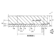
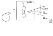
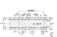
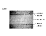
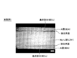
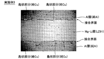
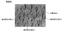
- FIG. 1 is a schematic perspective view showing an electronic apparatus according to a first embodiment of the present invention. It is sectional drawing of the clad material by 1st Embodiment of this invention. It is a schematic diagram for demonstrating the manufacturing method of the clad material by 1st Embodiment of this invention. It is sectional drawing of the clad material by 2nd Embodiment of this invention. It is a cross-sectional photograph of the comparative example 1 in the cross-sectional observation performed in order to confirm the effect of this invention. It is a cross-sectional photograph of Example 1 in the cross-sectional observation performed in order to confirm the effect of this invention. It is a cross-sectional photograph of Example 2 in the cross-sectional observation performed in order to confirm the effect of this invention.
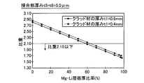
- 6 is a graph showing the specific gravity of the clad material with respect to the thickness ratio of the Mg—Li layer in a simulation performed to confirm the effect of the present invention. 6 is a graph showing the specific gravity of the clad material with respect to the thickness ratio of the Mg—Li layer in a simulation performed to confirm the effect of the present invention.
- the electronic device 100 is, for example, a portable electronic device.
- the electronic device 100 includes a box-shaped housing 1 used as a structural member of the electronic device 100, a substrate 2 disposed on the housing 1, a display unit connected to the substrate 2 and displaying an image or the like. 3 is provided.
- the housing 1 is an example of the “electronic device housing” in the claims.
- the housing 1 is composed of a clad material 10 as shown in FIG. Specifically, the housing 1 is composed of a clad material 10 including an Mg—Li layer 11, an Al layer 12, and a joint portion 13. Further, the clad material 10 is joined in a state where the Mg—Li layer 11 and the Al layer 12 are laminated in this order from the Z1 side toward the Z2 side. Further, in a cross-sectional view when the clad material 10 is cut in the thickness direction (Z direction), the joint portion 13 is disposed at the joint interface Ia between the Mg—Li layer 11 and the Al layer 12.
- the Mg—Li layer 11, the Al layer 12, and the bonding portion 13 are examples of “first layer”, “second layer”, and “first bonding portion” in the claims, respectively.
- the Mg—Li layer 11 is composed of an Mg—Li based alloy.
- the Mg—Li based alloy an Mg—Li alloy composed of 14% by mass of Li, the balance Mg and unavoidable impurity elements, LZ91 (9% by mass of Li, 1% by mass of Zn, the balance Mg and unavoidable Mg-Li-Zn alloy composed of impurity elements) and LA141 (Mg-Li-Al alloy composed of 14% by mass of Li, 1% by mass of Al, the balance Mg and inevitable impurity elements).
- the Mg—Li based alloy preferably contains about 6 mass% or more and about 15 mass% or less of Li. Note that the specific gravity of LZ91 as an example of the Mg—Li-based alloy is about 1.5.
- the Al layer 12 located on the surface layer of the clad material 10 is made of an Al-based alloy that is superior in corrosion resistance to the Mg—Li-based alloy and that can be easily processed by anodizing.
- the Al-based alloy includes pure Al and an Al alloy. Examples of pure Al include A1050 composed of 99.5% by mass or more of Al and other elements, and A1080 composed of 99.8% by mass or more of Al and other elements.
- Al alloys such as Al-2Si (Al-Si alloy composed of 2% by mass of Si and the balance Al and inevitable impurity elements) such as A4000 series Al-Si alloys and A5000 series Al-Mg alloys, etc. There is.
- the Al-based alloy constituting the Al layer 12 it is preferable to use pure Al having high ductility.
- the specific gravity of the Al-based alloy constituting the Al layer 12 is larger than the specific gravity of the Mg-Li-based alloy constituting the Mg—Li layer 11.
- the specific gravity of A1080 as an example of the Al-based alloy is about 2.7.
- the joint 13 is made of a Cu-based alloy.
- the Cu-based alloy includes pure Cu and Cu alloy.
- Examples of pure Cu include C1020 (oxygen-free copper), C1100 (tough pitch copper), C1201 (phosphorus deoxidized copper), and C1220 (phosphorus deoxidized copper).
- examples of the Cu alloy include a Cu—Ni alloy.
- the specific gravity of the Cu-based alloy constituting the joint 13 is larger than the specific gravity of the Mg-Li-based alloy constituting the Mg—Li layer 11 and the specific gravity of the Al-based alloy constituting the Al layer 12.
- the specific gravity of C1020 as an example of a Cu-based alloy is about 8.9.
- the contacting layers are firmly bonded by atomic diffusion, compound formation, or the like. Specifically, in the cladding material 10, not only the Al layer 12 and the joint 13 are firmly bonded at the bonding interface Ia between the Mg—Li layer 11 and the Al layer 12, but also the Mg—Li layer 11. As a result, the Mg—Li layer 11 and the Al layer 12 are joined together.
- the specific gravity of the clad material 10 is 2.10 or less, which is significantly smaller than the specific gravity (about 2.7) of the plate material of A1080, which is generally used Al.
- the specific gravity of the clad material 10 is preferably about 2.00 or less, and more preferably about 1.90 or less.
- the thickness ratio of the Mg—Li layer 11 ((t2 / t1) ⁇ 100 (%)) is set to the clad material 10 It is preferable to increase it to about 60% or more of the thickness t1.
- the thickness ratio of the Mg—Li layer 11 is more preferably about 90% or less of the thickness t 1 of the clad material 10.
- the joint portion 13 is arranged in an island shape on the joint interface Ia.
- the joint portion 13 is not formed in a layer shape at the joint interface Ia, but includes a plurality of island portions 13a.
- the island-like portions 13a are distributed and arranged over the entire bonding interface Ia, rather than being concentrated in a part of the bonding interface Ia.
- joint portion 13 is disposed in a portion of about 10% or more and about 90% or less of the joint interface Ia in the cross-sectional view (the existence rate is about 10% or more and about 90% or less in the cross-sectional view). Is preferred.
- the joint portion 13 is disposed in a portion of about 20% or more and about 80% or less of the joint interface Ia in a cross-sectional view.
- the above measurement is performed at a plurality of different measurement positions (for example, three or more and ten or less measurement positions) of the joint portion 13, and the average is defined as the presence rate (%) of the joint portion 13.
- the bonding portion 13 is about 4% or more and about 70% or less of the surface (peeling surface) on the bonding interface Ia side of the peeled Al layer 12. It is preferable to arrange in the part.
- the peel strength (peel strength) between the Mg—Li layer 11 and the joint 13 when peeling the clad material 10 at the joint interface Ia is preferably about 1.0 N / mm or more.
- the peel strength between the Mg—Li layer 11 and the bonding portion 13 is more preferably about 1.7 N / mm or more, and further preferably about 3.5 N / mm or more.
- the thickness t 2 of the Mg—Li layer 11 is preferably larger than any of the thickness t 3 of the Al layer 12 and the thickness t 4 of the joint portion 13.
- the thickness t2 is preferably about 60% or more of the thickness t1 of the clad material 10. Further, the thickness t2 is more preferably about 75% or more of the thickness t1, and further preferably about 90% or less.
- the thickness t4 of the joint portion 13 made of a Cu-based alloy having a large specific gravity is preferably not more than the thickness t2 of the Mg—Li layer 11 and not more than the thickness t3 of the Al layer 12.
- the thickness t4 is preferably about 6 ⁇ m or less.
- the thickness t4 is preferably about 0.5 ⁇ m or more.
- an Mg—Li plate material 111 made of an Mg—Li base alloy, an Al plate material 112 made of an Al base alloy, and a Cu plate material 113 made of a Cu base alloy are prepared. To do.
- the Mg—Li plate material 111, the Al plate material 112, and the Cu plate material 113 are annealed materials produced by annealing for a predetermined time under a predetermined temperature condition.
- the thickness of each of the Mg—Li plate material 111, the Al plate material 112, and the Cu plate material 113 is adjusted so that the specific gravity of the clad material 10 after joining becomes 2.10 or less.
- the Mg—Li plate material 111, the Cu plate material 113, and the Al plate material 112 are successively laminated in this order.
- the respective plate materials are laminated so as to form an overlay type clad material.
- the three laminated metal plates are continuously hot-rolled using the rolling roll 101.
- the temperature conditions T of hot rolling are about 150 degreeC or more and about 300 degrees C or less.
- the Mg—Li layer 11 and the Al layer 12 are laminated in this order, and the clad material 10 in which the joint portion 13 is disposed at the joint interface Ia between the Mg—Li layer 11 and the Al layer 12. Is produced.
- the thickness t4 of the joint 13 is equal to or less than a certain value, the elongation of the joint 13 during hot rolling cannot follow the elongation of the Mg—Li layer 11 and the Al layer 12, and the joint 13 breaks.
- an island-shaped portion 13 a is formed in the joint portion 13.
- diffusion annealing is performed on the clad material 10 under a temperature condition of about 100 ° C. or more and about 300 ° C. or less for a predetermined time (for example, about 5 minutes).
- the clad material 10 used for the structural member (housing 1) of the electronic device 100 is manufactured.
- the Mg—Li layer 11 composed of the Mg alloy is composed of the Mg—Li based alloy, so that the Mg—Li based alloy containing Li is used to form the Mg alloy.
- the specific gravity of the Mg—Li layer 11 can be made smaller than in the case where the layer to be formed is made of AZ80. Thereby, it can suppress that the specific gravity of the clad material 10 becomes 2.10 or less, and becomes large. Further, since the clad material 10 includes the Al layer 12, the corrosion resistance of the clad material 10 can be improved. As a result, the clad material 10 that is lightweight and has high corrosion resistance can be obtained.
- the Mg—Li base alloy constituting the Mg—Li layer 11 is easier to join with the joint portion 13 made of a Cu base alloy than an Mg alloy mainly containing Al in addition to Mg.
- the housing 1 (cladding material 10) particularly suitable for the portable electronic device 100 that is required to be reduced in weight.
- the joint portion 13 is arranged in an island shape on the joint interface Ia.
- the joining part 13 composed of a Cu-based alloy having a specific gravity larger than that of the Mg—Li based alloy and the Al based alloy is obtained. Can be reduced.
- the joint portion 13 is disposed in a portion of about 10% or more (preferably, a portion of about 20% or more) of the joint interface Ia in a cross-sectional view. If comprised in this way, the joining strength in the joining interface Ia can be ensured reliably. Further, the joint portion 13 is disposed in a portion of about 90% or less (more preferably, a portion of about 80% or less) of the joint interface Ia in a cross-sectional view. With this configuration, it is possible to suppress an excess of the joint portion 13 made of a Cu-based alloy having a specific gravity greater than that of the Mg—Li-based alloy and the Al-based alloy. Can be suppressed.
- the thickness t4 of the joint 13 in a cross-sectional view is set to about 0.5 ⁇ m or more, the joint 13 can be sufficiently secured, so that the joint at the joint interface Ia can be secured. It can suppress that intensity
- the thickness t2 of the Mg—Li layer 11 is set to about 60% or more of the thickness t1 of the clad material 10, so that the Mg—Li based alloy, the Al based alloy, and the Cu based Since the ratio of the Mg—Li based alloy having the smallest specific gravity among the alloys can be sufficiently increased, the weight of the clad material 10 can be effectively reduced. Further, by making the thickness t2 about 90% or less of the thickness t1, the thickness t3 of the Al layer 12 composed of the Al-based alloy is prevented from being sufficiently secured, and the corrosion resistance of the clad material 10 is lowered. Can be suppressed. Moreover, it can suppress that the junction part 13 is not ensured enough, and can suppress that the joining strength in the joining interface Ia becomes small.
- the peel strength between the Mg—Li layer 11 and the joint portion 13 is set to about 1.0 N / mm or more, so that the Mg—Li through the joint portion 13 is increased.
- the bonding strength between the layer 11 and the Al layer 12 can be reliably ensured.
- the Mg—Li base alloy constituting the Mg—Li layer 11 contains about 6 mass% or more of Li, so that the content of Li in the Mg—Li base alloy is increased. Can be ensured sufficiently, so that the Mg—Li layer 11 can be sufficiently reduced in weight. Furthermore, since the Mg—Li based alloy contains about 6 mass% or more of Li, the ductility of the Mg—Li layer 11 can be improved, and the press workability of the clad material 10 can be improved. In addition, since the Mg—Li based alloy contains about 15% by mass or less of Li, it is possible to prevent the Mg—Li based alloy from containing a large amount of Li which lowers the corrosion resistance. Can be ensured.
- the clad material 210 includes an Al layer 214 and a joint 215 in addition to the Mg—Li layer 211, the Al layer 212, and the joint 213. Further, the clad material 210 is joined in a state in which the Al layer 214, the Mg—Li layer 211, and the Al layer 212 are laminated in this order from the Z1 side to the Z2 side. Further, in a cross-sectional view when the clad material 210 is cut in the thickness direction (Z direction), the joint portion 213 is disposed at the joint interface Ia between the Mg—Li layer 211 and the Al layer 212 on the Z2 side.
- the joint portion 215 is disposed at the joint interface Ib between the Mg—Li layer 211 and the Al layer 214 on the Z1 side.
- the Mg—Li layer 211, the Al layers 212 and 214, and the joint portions 213 and 215 are respectively “first layer”, “second layer”, “third layer”, and “first joint” in the claims. Part “and" second joint part ".
- the Mg—Li layer 211 is made of an Mg—Li based alloy.
- Both the Al layers 212 and 214 located on the surface layer of the clad material 210 are made of an Al-based alloy.
- the Al layers 212 and 214 are preferably made of an Al-based alloy having substantially the same composition. Further, the thickness t13 of the Al layer 212 and the thickness t15 of the Al layer 214 are preferably substantially the same. Accordingly, it is not necessary to strictly distinguish the front and back of the clad material 210.
- the joints 213 and 215 are made of a Cu-based alloy.
- the clad material 210 not only the Al layer 212 and the joint 213 are firmly joined at the joint interface Ia between the Mg—Li layer 211 and the Al layer 212, but also the Mg—Li layer 211 and the joint.
- the Mg—Li layer 211 and the Al layer 212 are bonded.
- the bonding interface Ib between the Mg—Li layer 211 and the Al layer 214 not only the Al layer 214 and the bonding portion 215 are firmly bonded, but also the Mg—Li layer 211 and the bonding portion 215 are firmly bonded.
- the Mg—Li layer 211 and the Al layer 214 are joined.
- the specific gravity of the clad material 210 is 2.10 or less, which is significantly smaller than the specific gravity (about 2.7) of a plate material of A1080, which is generally widely used Al.
- the specific gravity of the clad material 210 is preferably about 2.00 or less, and more preferably about 1.90 or less.
- the thickness ratio of the Mg—Li layer 211 ((t12 / t11) ⁇ 100 (%)) is set to the clad material 210. It is preferable to increase it to about 60% or more of the thickness t11. In addition, the thickness ratio of the Mg—Li layer 211 is more preferably about 90% or less of the thickness t11 of the clad material 210.
- the joint portions 213 and 215 are arranged in an island shape at the joint interfaces Ia and Ib, respectively. That is, the joint portions 213 and 215 are not formed in layers at the joint interfaces Ia and Ib, respectively, and are composed of a plurality of island portions 213a and 215a. Further, the joint portion 213 is disposed at a portion of about 10% or more and about 90% or less of the joint interface Ia in the cross-sectional view (the existence rate is about 10% or more and about 90% or less in the cross-sectional view). Is preferred. Similarly, it is preferable that the joint portion 215 is disposed at a portion of about 10% or more and about 90% or less of the joint interface Ib in a cross-sectional view.
- the presence rate (%) of the joint portion 215 is calculated by ((L2a + L2b + L2c + L2d) / L) ⁇ 100. Moreover, it measures in the several different measurement position of the junction parts 213 and 215, and makes the average the presence rate (%) of the junction parts 213 and 215, respectively.
- the joint portion 213 is disposed at a portion of about 20% or more and about 80% or less of the joint interface Ia in a cross-sectional view.
- the joint portion 215 is disposed at a portion of about 20% or more and about 80% or less of the joint interface Ib in a cross-sectional view.
- the bonding portion 213 is about 4% or more and about 70% or less of the surface (peeling surface) on the bonding interface Ia side of the peeled Al layer 212. It is preferable to arrange in the part.
- the bonding portion 215 is formed at a portion of about 4% or more and about 70% or less of the surface on the bonding interface Ib side of the peeled Al layer 214. Preferably they are arranged.
- the peel strength (peel strength) between the Mg—Li layer 211 and the joint portion 213 when the clad material 210 is peeled off at the joint interface Ia is preferably about 1.0 N / mm or more.
- the peel strength (peel strength) between the Mg—Li layer 211 and the joint 215 when the clad material 210 is peeled at the joint interface Ib is preferably about 1.0 N / mm or more.
- the peel strength between the Mg—Li layer 211 and the bonding portion 213 (215) is more preferably about 1.7 N / mm or more, and about 3.5 N / mm or more. Is more preferable.
- the thickness t12 of the Mg—Li layer 211 is larger than any of the thickness t13 of the Al layer 212, the thickness t14 of the joint portion 213, the thickness t15 of the Al layer 214, and the thickness t16 of the joint portion 215. Larger is preferable.
- the thickness t12 is preferably about 60% or more of the thickness t11 of the clad material 210.
- the thickness t12 is more preferably about 75% or more of the thickness t11, and further preferably about 90% or less.
- the thickness t14 of the joint portion 213 and the thickness t16 of the joint portion 215 made of a Cu-based alloy having a large specific gravity are both the thickness t12 or less of the Mg—Li layer 211, the thickness t13 or less of the Al layer 212, and Al
- the thickness of the layer 214 is preferably t15 or less.
- both the thicknesses t14 and t16 are preferably about 6 ⁇ m or less.
- the thicknesses t14 and t16 are both preferably about 0.5 ⁇ m or more.
- the other structure of the clad material 210 of 2nd Embodiment is the same as that of the clad material 10 of the said 1st Embodiment.
- the manufacturing method of the clad material 210 of the second embodiment is the same as that of the clad material 10 of the first embodiment except that the Al plate material, the Cu plate material, the Mg—Li plate material, the Cu plate material, and the Al plate material are laminated in this order. This is the same as the manufacturing method.
- the Mg—Li layer 211 made of the Mg alloy is made of the Mg—Li based alloy
- the clad material 210 includes the Al layers 212 and 214.
- the bonding portions 213 and 215 can sufficiently secure the bonding strength at the bonding interface Ia to suppress the separation of the Mg—Li layer 211 and the Al layer 212 from each other, and the bonding strength at the bonding interface Ib. Is sufficiently secured, and the Mg—Li layer 211 and the Al layer 214 can be prevented from being separated from each other.
- the joint portions 213 and 215 are arranged in an island shape at the joint interfaces Ia and Ib, respectively.
- the specific gravity of the clad material 210 can be more reliably reduced to 2.10 or less, and the clad material 210 can be reduced in weight.
- the joint portion 213 is disposed in a portion of about 10% or more (preferably, a portion of about 20% or more) of the joint interface Ia in a cross-sectional view.
- the joint portion 215 is disposed in a portion of about 10% or more (preferably, a portion of about 20% or more) of the joint interface Ib in a cross-sectional view.
- the joint portion 213 is disposed in a portion of about 90% or less (more preferably, a portion of about 80% or less) of the joint interface Ia in a cross-sectional view.
- the joint portion 215 is disposed in a portion of about 90% or less (more preferably, a portion of about 80% or less) of the joint interface Ib in a cross-sectional view. If comprised in this way, it can suppress that the specific gravity of the clad material 210 becomes large.
- the thickness t14 of the joint portion 213 and the thickness t16 of the joint portion 215 in cross-sectional view are about 0.5 ⁇ m or more, the joint strength at the joint interfaces Ia and Ib is reduced. Can be suppressed. Further, if the thicknesses t14 and t16 are about 6 ⁇ m or less, the specific gravity of the clad material 210 can be suppressed from increasing.
- the peel strength between the Mg—Li layer 211 and the joint portion 213 is about 1.0 N / mm or more, and the Mg—Li layer 211 and the joint portion 215 are The peel strength between is about 1.0 N / mm or more. Accordingly, the bonding strength between the Mg—Li layer 211 and the Al layer 212 via the bonding portion 213 can be reliably ensured, and the Mg—Li layer 211 and the Al layer 214 via the bonding portion 215 can be secured. It is possible to ensure the bonding strength between the two.
- the clad material 210 is bonded to the surface of the Mg—Li layer 211 opposite to the Al layer 212 (Z1 side), and is an Al layer made of an Al-based alloy. 214, and in a cross-sectional view, a bonding portion 215 that is disposed at a bonding interface Ib between the Mg—Li layer 211 and the Al layer 214 and is made of a Cu-based alloy.
- the Mg—Li layer 211 having low corrosion resistance is sandwiched between the Al layer 212 and the Al layer 214 made of an Al-based alloy, so that the corrosion resistance of the clad material 210 can be effectively improved.
- the clad material 210 includes an Al layer 212 made of an Al-based alloy, an Mg—Li layer 211 made of an Mg—Li-based alloy, and an Al layer 214 made of an Al-based alloy in this order. Since the -Li layer 211 has a symmetric layer structure as a center, it is possible to effectively suppress the occurrence of warpage in the clad material 210. Thereby, the clad material 210 suitable for the housing
- the clad material 210 of Example 1 corresponding to the second embodiment was produced. Specifically, first, an Mg—Li plate made of LZ91 (Mg—Li—Zn alloy), a pair of Al plates made of A1080 (pure Al), and C1020 (pure Cu). A pair of Cu plate materials was prepared.
- the specific gravity of LZ91 is 1.50
- the specific gravity of A1080 is 2.70
- the specific gravity of C1020 is 8.94.
- an Al plate material, a Cu plate material, an Mg—Li plate material, a Cu plate material, and an Al plate material are successively laminated in this order.
- stacked on the temperature conditions described in the said 1st Embodiment was hot-rolled continuously using a rolling roll (refer FIG. 3), and described in the said 1st Embodiment. Diffusion annealing is performed under temperature conditions.
- the Al layer 214, the Mg—Li layer 211, and the Al layer 212 are laminated in this order, and the bonding interface Ia between the Mg—Li layer 211 and the Al layer 212 and the bonding interface between the Mg—Li layer 211 and the Al layer 214 are stacked.
- the clad material 210 of Example 1 shown in FIG. 4 in which the joint portions 213 and 215 are arranged on Ib was produced.
- Example 1 when the thickness t11 of the clad material 210 is 480 ⁇ m, the thickness t12 of the Mg—Li layer 211 is 318 ⁇ m, and the thickness t13 of the Al layer 212 and the thickness t15 of the Al layer 214 are both 80 ⁇ m.
- the thicknesses of the Mg—Li plate, the pair of Al plates, and the pair of Cu plates were adjusted so that the thickness t14 of the joint 213 and the thickness t16 of the joint 215 were both 1 ⁇ m.
- the specific gravity of the clad material 210 of Example 1 was 1.93.
- Example 2 the clad material 210 of Example 2 was produced.
- the clad material 210 was produced in the same manner as the clad material 210 of Example 1, except that the thickness t12 was 317 ⁇ m and the thicknesses t14 and t16 were both 1.5 ⁇ m.
- the specific gravity of the clad material 210 of Example 3 was 1.95.
- Example 3 a clad material 210 was produced in the same manner as the clad material 210 of Example 1, except that the thickness t12 was 314 ⁇ m and the thicknesses t14 and t16 were both 3 ⁇ m.
- the specific gravity of the clad material 210 of Example 3 was 1.99.
- Example 4 a clad material 210 was produced in the same manner as the clad material 210 of Example 1, except that the thickness t12 was 308 ⁇ m and the thicknesses t14 and t16 were both 6 ⁇ m.
- the specific gravity of the clad material 210 of Example 3 was 2.09.
- Comparative Example 1 a clad material was fabricated in the same manner as the clad material 210 of Example 1 except that the thickness of the Mg—Li layer was 320 ⁇ m and a pair of joints were not provided.
- the specific gravity of the clad material of Comparative Example 1 was 1.90.
- a clad material of Comparative Example 2 was produced.
- a clad material was produced in the same manner as the clad material 210 of Example 1, except that the thickness of the Mg—Li layer was 296 ⁇ m and the thickness of the pair of joint portions was both 12 ⁇ m.
- the clad material of Comparative Example 3 was produced.
- a clad material was produced in the same manner as the clad material 210 of Example 1 except that the thickness of the Mg—Li layer was 272 ⁇ m and the thickness of the pair of joints was both 24 ⁇ m.
- the specific gravity of the clad material of Comparative Examples 2 and 3 was 2.27 and 2.64, respectively, both exceeding the upper limit (2.10) of the specific gravity of the clad material of the present invention.
- a clad material of Comparative Example 4 was produced.
- Comparative Example 4 instead of the Mg—Li layer 211 composed of LZ91 of Example 1, it was composed of AZ31 composed of 3% by mass of Al, 1% Zn, the balance Mg, and unavoidable impurity elements.
- A1050 was used instead of A1080 constituting the Al layers 212 and 214 of Example 1. That is, in Comparative Example 4, no Mg alloy containing Li was used.
- the thickness of the Mg layer was 320 ⁇ m
- the thickness of the pair of Al layers was both 80 ⁇ m
- the thickness of the pair of joints was both 20 ⁇ m.
- a clad material was produced in the same manner as the clad material 210 of Example 1.
- the specific gravity of the clad material of Comparative Example 4 was 2.61.
- Table 1 shows the thickness ratio and specific gravity of the clad materials of Examples 1 to 4 and Comparative Examples 1 to 4.
- the joining portion was formed to have a sufficiently large thickness of 12 ⁇ m in the clad material of Comparative Example 2.
- the joint portion having a certain thickness such as Example 4 can be formed in a layer shape instead of an island shape by adjusting the material of the joint portion, the hot rolling conditions, and the like.
- the existence ratios of the joint portions in the four predetermined measurement ranges of Example 1 were 18.2%, 15.1%, 18.6%, and 17.2%, respectively. Thereby, the abundance ratio of the joints in the clad material of Example 1 averaged 17.3%.
- the abundance ratios of the joint portions in the predetermined measurement ranges at the four locations in Example 2 were 21.7%, 27.4%, 19.0%, and 28.4%, respectively. Thereby, the abundance ratio of the joints in the clad material of Example 2 averaged 24.1%.
- the existence ratios of the joint portions in the four predetermined measurement ranges in Example 3 were 59.7%, 54.7%, 53.4%, and 34.6%, respectively. Thereby, the abundance ratio of the joints in the clad material of Example 3 was 50.6% on average.
- the cross-sectional view WHEREIN The presence rate of the junction part in the four predetermined measurement ranges of Example 4 was 92.6%, 70.7%, 87.3%, and 67.5%, respectively. Thereby, the abundance ratio of the joints in the clad material of Example 4 averaged 79.4%.
- a peeling test shown in FIG. 12 was performed on the clad material 210. Specifically, one side (the Mg—Li layer 211, the Al layer 212, and the joint 213 shown in FIG. 12) of the peeled interface (for example, the joint interface Ib shown in FIG. 12) is fixed to the fixing member 102 and peeled off. The other side of the interface (Al layer 214 and joint 215 shown in FIG. 12) was further peeled by pulling in the Z1 direction.
- the peel strength (joint strength) between the Mg—Li layer 211 and the joint portion 215 is obtained.
- F was determined as a load per unit width. Note that since the bonding strength between the Al layer and the bonding portion is larger than the bonding strength between the Mg—Li layer and the bonding portion, the peel strength between the Mg—Li layer and the bonding portion was measured. In addition, it is considered that the peel strength between the Mg—Li layer 211 and the joint portion 213 is almost the same as the peel strength between the Mg—Li layer 211 and the joint portion 215.
- the peel strength was measured as an average load in a length range of 5 mm to 10 mm.
- the peel strength was measured at five locations, and the average was taken as the peel strength of the clad materials of Examples 1 to 4 and Comparative Examples 1 to 4.
- Example 4 even when the abundance of the joint in the cross-sectional view is 79.4% and there is no joint at the entire joint interface, the peel strength is 5 N / mm or more, which is extremely It was confirmed that a large bonding strength was generated.
- Comparative Example 3 peeling was not possible (peeling not possible). Further, as shown in Comparative Example 4, even when the joining portion has a sufficient thickness of 20 ⁇ m, when an Mg—Al based alloy not containing Li is used as the Mg layer instead of the Mg—Li based alloy. The peel strength was reduced to 1.5 N / mm. This peel strength is smaller than the peel strength (1.741 N / mm) of Example 2 having a thickness as small as 1.5 ⁇ m. Accordingly, it was confirmed that the Mg—Li based alloy was superior in adhesiveness to the joint composed of the Cu based alloy, compared to the Mg alloy not containing Li like AZ31.
- the thickness t11 of the clad material 210 is set to 0.6 mm, and the thickness t14 of the joint portion 213 and the thickness t16 of the joint portion 215 are both set to 1 ⁇ m, 5 ⁇ m, or 10 ⁇ m.
- the specific gravity of the clad material 210 relative to the plate thickness ratio was determined.
- the specific gravity of the clad material 210 with respect to the thickness ratio was determined.
- the plate thickness ratio (%) of the Al layers 212 and 214 is both (100 ⁇ (plate thickness ratio of the Mg—Li layer 211 + plate thickness ratio of the joint portion 213 + plate thickness ratio of the joint portion 215)) / 2
- (Simulation results) 18 to 20 show the clad material with respect to the plate thickness ratio of the Mg—Li layer 211 when the thickness t14 of the joint portion 213 and the thickness t16 of the joint portion 215 are 1 ⁇ m, 5 ⁇ m, and 10 ⁇ m, respectively.
- the specific gravity of 210 is shown.
- the clad material has a thickness ratio of the Mg—Li layer 211 of about 50% or more. It was found that the specific gravity of 210 was 2.10 or less.
- the thickness ratio of the Mg—Li layer 211 is reduced to about 50% in order to reduce the amount of Mg—Li based alloy (LZ91) used. Even if it is made smaller, it has been found from the results of the above peeling experiment that the specific gravity of the clad material 210 can be reduced to 2.10 or less while ensuring a sufficient bonding strength. As shown in FIG. 18, when the thickness t1 is 0.4 mm, the thickness ratio of the Mg—Li layer 211 is set to about 53% or more, so that sufficient clad strength is ensured and the clad material It has been found that the specific gravity of 210 can be reduced to 2.10 or less.
- the thickness ratio of the Mg—Li layer 211 is about 72% or more, the clad material 210 It was found that the specific gravity was 2.10 or less. Therefore, even when the thicknesses t14 and t16 are 10 ⁇ m and the thicknesses of the joints 213 and 215 are sufficiently secured, by setting the thickness ratio of the Mg—Li layer 211 to about 67% or more, It was found that the specific gravity of the clad material 210 can be reduced to 2.10 or less.
- the specific gravity of the clad material 210 can be reduced to 2.10 or less by increasing the thickness ratio of the Mg—Li layer 211.
- the specific gravity of the clad material 210 is 2.10 or less by setting the plate thickness ratio of the Mg—Li layer 211 to about 74% or more. It turns out that it can be made smaller. Even if the thicknesses t14 and t16 are larger than 10 ⁇ m, it is considered that the specific gravity of the clad material 210 can be made 2.10 or less by adjusting the thickness ratio of the Mg—Li layer 211. .
- the thickness ratio of the Mg—Li layer 211 is about 59% or more, the cladding material 210 It was found that the specific gravity was 2.10 or less. Further, it was found that when the thickness t1 is 0.4 mm, the specific gravity of the clad material 210 is 2.10 or less if the thickness ratio of the Mg—Li layer 211 is approximately 62% or more.
- the clad material 10 is formed by laminating the Mg—Li layer 11 and the Al layer 12 (second layer) in this order, and is bonded to the bonding interface Ia between the Mg—Li layer 11 and the Al layer 12.
- An example of a clad material in which a portion 13 (first bonding portion) is disposed is shown.
- the clad material 210 includes an Al layer 214 (third layer), an Mg—Li layer 211 ( The first layer) and the Al layer 212 (second layer) are laminated in this order, and the bonding interface Ia between the Mg—Li layer 211 and the Al layer 212 and the bonding interface Ib between the Mg—Li layer 211 and the Al layer 214 are
- the example which is a clad material in which the joint part 213 (first joint part) and the joint part 215 (second joint part) are arranged is shown, the present invention is not limited to this.
- a metal layer may be provided.
- another metal layer may be bonded to the surface of the second layer opposite to the first layer.
- the present invention is not limited to this. You may use the clad material of this invention for structural materials uses, such as a motor vehicle other than the housing
- the junction parts 13 (213) and 215 each extend over the whole joining interface Ia and Ib, respectively.
- the first (second) joint may be disposed only at a part of the joint interface.
- the clad material of the present invention may be constituted by an inlay type clad material in which the joint portion is arranged only at a part of the joint interface, instead of the overlay type clad material.
- the junction part does not need to be formed in an island shape. That is, as long as the specific gravity of the clad material is 2.10 or less, the joint portion may be formed in a layer shape.
Landscapes
- Chemical & Material Sciences (AREA)
- Engineering & Computer Science (AREA)
- Mechanical Engineering (AREA)
- Materials Engineering (AREA)
- Metallurgy (AREA)
- Organic Chemistry (AREA)
- Physics & Mathematics (AREA)
- Thermal Sciences (AREA)
- Crystallography & Structural Chemistry (AREA)
- Microelectronics & Electronic Packaging (AREA)
- Pressure Welding/Diffusion-Bonding (AREA)
- Laminated Bodies (AREA)
Abstract
Description
<電子機器の構成>
まず、図1および図2を参照して、本発明の第1実施形態による電子機器100の構成について説明する。
筐体1は、図2に示すように、クラッド材10から構成されている。具体的には、筐体1は、Mg-Li層11と、Al層12と、接合部13とを備えるクラッド材10から構成されている。また、クラッド材10は、Z1側からZ2側に向かって、Mg-Li層11およびAl層12がこの順に積層された状態で接合されている。また、クラッド材10を厚み方向(Z方向)に切断した際の断面視において、接合部13は、Mg-Li層11とAl層12との接合界面Iaに配置されている。なお、Mg-Li層11、Al層12および接合部13は、それぞれ、特許請求の範囲の「第1層」、「第2層」および「第1接合部」の一例である。
次に、図1~図3を参照して、本発明の第1実施形態によるクラッド材10の製造方法について説明する。
第1実施形態では、以下のような効果を得ることができる。
次に、図4を参照して、本発明の第2実施形態について説明する。第2実施形態では、クラッド材210が5層構造を有する場合について説明する。
第2実施形態では、クラッド材210は、Mg-Li層211と、Al層212と、接合部213とに加えて、Al層214と接合部215とを備えている。また、クラッド材210は、Z1側からZ2側に向かって、Al層214、Mg-Li層211およびAl層212がこの順に積層された状態で接合されている。また、クラッド材210を厚み方向(Z方向)に切断した際の断面視において、接合部213は、Mg-Li層211とZ2側のAl層212との接合界面Iaに配置されている。また、断面視において、接合部215は、Mg-Li層211とZ1側のAl層214との接合界面Ibに配置されている。なお、Mg-Li層211、Al層212、214、接合部213および215は、それぞれ、特許請求の範囲の「第1層」、「第2層」、「第3層」、「第1接合部」および「第2接合部」の一例である。
第2実施形態では、以下のような効果を得ることができる。
次に、図3~図20を参照して、本発明の効果を確認するために行った実験およびシミュレーションについて説明する。なお、実験として、接合部の存在率の測定と、ピール強度の測定とを行った。また、シミュレーションとして、クラッド材の厚みおよび接合部の厚みを所定の値に設定した際の、Mg-Li層の板厚比率に対するクラッド材の比重を求めた。
まず、上記第2実施形態に対応する実施例1のクラッド材210を作製した。具体的には、まず、LZ91(Mg-Li-Zn合金)から構成されるMg-Li板材と、A1080(純Al)から構成される一対のAl板材と、C1020(純Cu)から構成される一対のCu板材を準備した。ここで、LZ91の比重は1.50であり、A1080の比重は、2.70であり、C1020の比重は、8.94である。

そして、実施例1~4および比較例1および2のクラッド材について、クラッド材を厚み方向に切断して断面写真を撮影した。その後、断面写真から、断面視における接合界面での接合部の存在率(%)を算出した。この際、実施例1~4および比較例1および2のクラッド材について、接合界面に沿う方向において測定範囲の長さL(図4参照)を1000μmに設定した際の、接合部の島状部分が存在している合計の長さを取得した。そして、合計の長さを1000で除算し、100を乗算することによって、所定の測定範囲における接合部の存在率(%)を算出した。また、実施例1~4および比較例1および2の各々において、4箇所の異なる測定範囲で測定を行い、その平均をクラッド材における接合部の存在率(%)とした。
図5~図10に実施例1~4および比較例1および2のクラッド材についての断面写真をそれぞれ示す。実施例1~4および比較例2のクラッド材では、Al層とMg-Li層との接合界面に純Cuから構成された接合部が存在していた。なお、図6~図10の写真では、白線で囲む部分が接合部に該当する。
次に、実施例1~4および比較例1~4のクラッド材について剥離試験を行った。この剥離試験では、図11に示すように、まず、ペンチなどの図示しない冶具を用いてクラッド材210の端部の接合界面を強制的に剥離させた。なお、接合強度が高く強制的な剥離が困難なクラッド材については、熱間圧延時に、端部を予め剥離しやすいようにクラッド材を接合させた。
上記表1および図13に示す剥離試験の結果としては、純Cuから構成される接合部をAl層とMg-Li層との接合界面に設けない比較例1では、ピール強度が1.0N/mm未満に小さくなった一方、純Cuから構成される接合部を接合界面に設けた実施例1~4および比較例2~4では、ピール強度が1.2N/mm以上(1.0N/mm以上)に大きくなった。これにより、純Cuから構成される接合部を接合界面に設けることによって、接合強度を確実に向上させることができる点が確認できた。特に、実施例1では、比重が1.93でかなり小さいにもかかわらず、ピール強度が1.217N/mmになり、十分な接合強度が得られることが判明した。
また、実施例1~4のクラッド材において、剥離試験で剥離した表面のうち、Al層側の表面(剥離面)を観察した。図14~図17に、実施例1~4のクラッド材の剥離面の写真をそれぞれ示す。実施例1~4のクラッド材の剥離面では、共に、接合部(島状部分)が接合界面(剥離面)の全体に分散していることが確認できた。
また、実施例1~4のクラッド材における平面写真から、剥離面における接合部の存在率を測定した。
上記表1および図13に示すように、実施例1~4において、剥離面における接合部の存在率は、断面視における接合部の存在率よりも小さくなった。これは、剥離試験において接合部(島状部分)が脱落したり、Mg-Li層側に残ったりしたからであると考えられる。
シミュレーションとして、A1080から構成されたAl層214、LZ91から構成されたMg-Li層211およびA1080から構成されたAl層212がこの順に積層され、Mg-Li層211とAl層212との接合界面IaおよびMg-Li層211とAl層214との接合界面Ibにそれぞれ、C1020から共に構成された接合部213および215が配置された、図4に示すクラッド材210を想定した。そして、想定したクラッド材210において、Mg-Li層211の板厚比率に対するクラッド材210の比重を求めた。
図18~図20に、それぞれ、接合部213の厚みt14および接合部215の厚みt16が1μmの場合、5μmの場合、および、10μmの場合における、Mg-Li層211の板厚比率に対するクラッド材210の比重を示す。図18に示す厚みt14およびt16が1μmの場合で、かつ、クラッド材210の厚みt11が0.6mmの場合では、Mg-Li層211の板厚比率が約50%以上であれば、クラッド材210の比重が2.10以下になることが判明した。このことから、クラッド材210の厚みt11が0.6mmの場合には、Mg-Li基合金(LZ91)の使用量を減少させるために、Mg-Li層211の板厚比率を約50%に小さくしたとしても、上記剥離実験の結果から十分な接合強度を確保しつつ、クラッド材210の比重を2.10以下に小さくすることができることが判明した。なお、図18に示すように、厚みt1が0.4mmである場合では、Mg-Li層211の板厚比率を約53%以上にすることによって、十分な接合強度を確保しつつ、クラッド材210の比重を2.10以下に小さくすることができることが判明した。
なお、今回開示された実施形態および実施例は、すべての点で例示であって制限的なものではないと考えられるべきである。本発明の範囲は、上記した実施形態および実施例の説明ではなく特許請求の範囲によって示され、さらに特許請求の範囲と均等の意味および範囲内でのすべての変更(変形例)が含まれる。
10、210 クラッド材
11、211 Mg-Li層(第1層)
12、212 Al層(第2層)
13、213 接合部(第1接合部)
100 電子機器
214 Al層(第3層)
215 接合部(第2接合部)
Ia (第1層と第2層との)接合界面
Ib (第1層と第3層との)接合界面
Claims (10)
- Mg-Li基合金から構成される第1層(11、211)と、
Al基合金から構成される第2層(12、212)と、
厚み方向に切断した際の断面視において、前記第1層と前記第2層との接合界面(Ia)に配置され、Cu基合金から構成される第1接合部(13、213)と、を備え、
比重が2.10以下である、クラッド材(10、210)。 - 前記第1接合部は、前記接合界面に島状に配置されている、請求項1に記載のクラッド材。
- 前記第1接合部は、前記断面視において、前記接合界面の10%以上90%以下の部分に配置されている、請求項2に記載のクラッド材。
- 前記第1接合部は、前記断面視において、前記接合界面の20%以上80%以下の部分に配置されている、請求項3に記載のクラッド材。
- 前記断面視における前記第1接合部の厚みは、0.5μm以上6μm以下である、請求項1~4のいずれか1項に記載のクラッド材。
- 前記断面視における前記第1層の厚みは、前記クラッド材の厚みの60%以上90%以下である、請求項1~4のいずれか1項に記載のクラッド材。
- 前記第1層と前記第1接合部との間のピール強度は、1.0N/mm以上である、請求項1~4のいずれか1項に記載のクラッド材。
- 前記第1層の前記第2層とは反対側の表面に接合され、Al基合金から構成される第3層(214)と、
前記断面視において、前記第1層と前記第3層との接合界面に配置され、Cu基合金から構成される第2接合部(215)と、をさらに備える、請求項1~4のいずれか1項に記載のクラッド材。 - 前記第1層を構成するMg-Li基合金は、6質量%以上15質量%以下のLiを含有する、請求項1~4のいずれか1項に記載のクラッド材。
- Mg-Li基合金から構成される第1層と、
Al基合金から構成される第2層と、
厚み方向に切断した際の断面視において、前記第1層と前記第2層との接合界面に配置され、Cu基合金から構成される第1接合部と、を備え、比重が2.10以下であるクラッド材からなる、電子機器用筐体(1)。
Priority Applications (4)
| Application Number | Priority Date | Filing Date | Title |
|---|---|---|---|
| KR1020177019161A KR101808999B1 (ko) | 2015-12-28 | 2016-12-15 | 클래드재 및 전자 기기용 하우징 |
| JP2017509082A JP6135835B1 (ja) | 2015-12-28 | 2016-12-15 | クラッド材および電子機器用筐体 |
| US15/543,628 US10532422B2 (en) | 2015-12-28 | 2016-12-15 | Clad material and electronic device housing |
| CN201680005863.5A CN107206747B (zh) | 2015-12-28 | 2016-12-15 | 包层材料和电子设备用壳体 |
Applications Claiming Priority (2)
| Application Number | Priority Date | Filing Date | Title |
|---|---|---|---|
| JP2015-256343 | 2015-12-28 | ||
| JP2015256343 | 2015-12-28 |
Publications (1)
| Publication Number | Publication Date |
|---|---|
| WO2017115661A1 true WO2017115661A1 (ja) | 2017-07-06 |
Family
ID=59225046
Family Applications (1)
| Application Number | Title | Priority Date | Filing Date |
|---|---|---|---|
| PCT/JP2016/087352 Ceased WO2017115661A1 (ja) | 2015-12-28 | 2016-12-15 | クラッド材および電子機器用筐体 |
Country Status (5)
| Country | Link |
|---|---|
| US (1) | US10532422B2 (ja) |
| JP (1) | JP6135835B1 (ja) |
| KR (1) | KR101808999B1 (ja) |
| CN (1) | CN107206747B (ja) |
| WO (1) | WO2017115661A1 (ja) |
Cited By (3)
| Publication number | Priority date | Publication date | Assignee | Title |
|---|---|---|---|---|
| JP2019166659A (ja) * | 2018-03-22 | 2019-10-03 | 富士通株式会社 | クラッド材、及びその製造方法、並びに電子機器 |
| US20220143742A1 (en) * | 2019-03-14 | 2022-05-12 | Hitachi Metals, Ltd. | Magnesium Clad Material, Electronic Device Housing, and Mobile Object Component |
| EP4326017A4 (en) * | 2021-05-08 | 2024-10-16 | Huawei Technologies Co., Ltd. | HOUSING, TERMINAL DEVICE AND PREPARATION METHOD FOR HOUSING |
Families Citing this family (4)
| Publication number | Priority date | Publication date | Assignee | Title |
|---|---|---|---|---|
| JP2020117804A (ja) * | 2019-01-24 | 2020-08-06 | 日立金属株式会社 | マグネシウムクラッド材および電子機器用筐体 |
| WO2021154275A1 (en) * | 2020-01-31 | 2021-08-05 | Hewlett-Packard Development Company, L.P. | Enclosures for electronic devices |
| CN112976718B (zh) * | 2021-02-05 | 2022-12-02 | 太原理工大学 | 一种1420Al-Li/Mg-9Li/1420Al-Li复合板及制备方法 |
| CN115647048A (zh) * | 2022-11-11 | 2023-01-31 | 昆明理工大学 | 一种高电磁屏蔽效能的铝/镁锂合金/铝层状复合材料及其制备方法 |
Citations (5)
| Publication number | Priority date | Publication date | Assignee | Title |
|---|---|---|---|---|
| JPH06328617A (ja) * | 1993-05-18 | 1994-11-29 | Nippon Steel Corp | マグネシウム−アルミニウムクラッド材 |
| JP2005281824A (ja) * | 2004-03-30 | 2005-10-13 | Sumitomo Metal Ind Ltd | マグネシウム合金とアルミニウムとのクラッド板およびその製造方法 |
| WO2011155214A1 (ja) * | 2010-06-10 | 2011-12-15 | ワシマイヤー株式会社 | 結合部材及びその製造方法 |
| JP2014013467A (ja) * | 2012-07-03 | 2014-01-23 | Nec Personal Computers Ltd | ノートブック型パーソナルコンピュータ |
| JP2015202680A (ja) * | 2014-04-16 | 2015-11-16 | 株式会社Neomaxマテリアル | クラッド材およびクラッド材の製造方法 |
Family Cites Families (6)
| Publication number | Priority date | Publication date | Assignee | Title |
|---|---|---|---|---|
| US3475140A (en) * | 1966-01-03 | 1969-10-28 | Texas Instruments Inc | Composite printing plate with a magnesium alloy bonded to an aluminum layer |
| JPS5830727B2 (ja) * | 1976-05-10 | 1983-07-01 | 富士通株式会社 | バブルドメイン用ガ−ネツト磁性薄膜 |
| JPS5830727A (ja) * | 1981-08-18 | 1983-02-23 | Sharp Corp | 液晶表示装置 |
| BE1014308A5 (nl) * | 2001-07-20 | 2003-08-05 | Wiele Michel Van De Nv | Werkwijze en inrichting voor het sturen van een opwikkelinrichting. |
| JP4117127B2 (ja) * | 2001-12-21 | 2008-07-16 | 新潟県 | アルミニウム被覆マグネシウム合金材及びその製造方法 |
| CN101530860B (zh) * | 2009-04-13 | 2011-05-04 | 西安建筑科技大学 | 一种铝镁超细晶多层结构复合板的制备方法 |
-
2016
- 2016-12-15 JP JP2017509082A patent/JP6135835B1/ja active Active
- 2016-12-15 WO PCT/JP2016/087352 patent/WO2017115661A1/ja not_active Ceased
- 2016-12-15 US US15/543,628 patent/US10532422B2/en active Active
- 2016-12-15 CN CN201680005863.5A patent/CN107206747B/zh active Active
- 2016-12-15 KR KR1020177019161A patent/KR101808999B1/ko active Active
Patent Citations (5)
| Publication number | Priority date | Publication date | Assignee | Title |
|---|---|---|---|---|
| JPH06328617A (ja) * | 1993-05-18 | 1994-11-29 | Nippon Steel Corp | マグネシウム−アルミニウムクラッド材 |
| JP2005281824A (ja) * | 2004-03-30 | 2005-10-13 | Sumitomo Metal Ind Ltd | マグネシウム合金とアルミニウムとのクラッド板およびその製造方法 |
| WO2011155214A1 (ja) * | 2010-06-10 | 2011-12-15 | ワシマイヤー株式会社 | 結合部材及びその製造方法 |
| JP2014013467A (ja) * | 2012-07-03 | 2014-01-23 | Nec Personal Computers Ltd | ノートブック型パーソナルコンピュータ |
| JP2015202680A (ja) * | 2014-04-16 | 2015-11-16 | 株式会社Neomaxマテリアル | クラッド材およびクラッド材の製造方法 |
Cited By (6)
| Publication number | Priority date | Publication date | Assignee | Title |
|---|---|---|---|---|
| JP2019166659A (ja) * | 2018-03-22 | 2019-10-03 | 富士通株式会社 | クラッド材、及びその製造方法、並びに電子機器 |
| JP7200491B2 (ja) | 2018-03-22 | 2023-01-10 | 富士通株式会社 | クラッド材の製造方法 |
| US20220143742A1 (en) * | 2019-03-14 | 2022-05-12 | Hitachi Metals, Ltd. | Magnesium Clad Material, Electronic Device Housing, and Mobile Object Component |
| US11931821B2 (en) * | 2019-03-14 | 2024-03-19 | Proterial, Ltd. | Magnesium clad material, electronic device housing, and mobile object component |
| EP4326017A4 (en) * | 2021-05-08 | 2024-10-16 | Huawei Technologies Co., Ltd. | HOUSING, TERMINAL DEVICE AND PREPARATION METHOD FOR HOUSING |
| US12558873B2 (en) | 2021-05-08 | 2026-02-24 | Huawei Technologies Co., Ltd. | Housing, terminal device, and housing manufacturing method |
Also Published As
| Publication number | Publication date |
|---|---|
| KR101808999B1 (ko) | 2017-12-13 |
| JP6135835B1 (ja) | 2017-05-31 |
| US20180326530A1 (en) | 2018-11-15 |
| CN107206747A (zh) | 2017-09-26 |
| US10532422B2 (en) | 2020-01-14 |
| KR20170089008A (ko) | 2017-08-02 |
| CN107206747B (zh) | 2018-11-30 |
| JPWO2017115661A1 (ja) | 2017-12-28 |
Similar Documents
| Publication | Publication Date | Title |
|---|---|---|
| JP6135835B1 (ja) | クラッド材および電子機器用筐体 | |
| JP4961512B2 (ja) | アルミニウム銅クラッド材 | |
| KR101418706B1 (ko) | 섀시 및 섀시의 제조 방법 | |
| WO2016147807A1 (ja) | アルミニウム合金製ブレージングシート | |
| JPWO2017170204A1 (ja) | 熱交換器用アルミニウム合金製ブレージングシート及びその製造方法 | |
| CN106531946B (zh) | 电池用引线部件和电池用引线部件的制造方法 | |
| CN108055835A (zh) | 金属层叠材料及其制造方法 | |
| JP6332108B2 (ja) | ヒートシンク付パワーモジュール用基板の製造方法 | |
| WO2013157455A1 (ja) | アルミニウムクラッド材の製造方法およびアルミニウムクラッド材 | |
| JP6364910B2 (ja) | クラッド材およびクラッド材の製造方法 | |
| JP7174361B2 (ja) | 金属部材の溶接構造の製造方法、及び金属部材の溶接構造 | |
| WO2020049885A1 (ja) | 金属部材の溶接構造、及び金属部材の溶接構造の製造方法 | |
| JP2020117804A (ja) | マグネシウムクラッド材および電子機器用筐体 | |
| JP2015226928A (ja) | アルミニウム材と銅材の積層材の製造方法 | |
| JP5954072B2 (ja) | コネクタ端子用材料、コネクタ端子、及びコネクタ端子用材料の製造方法 | |
| JP5917903B2 (ja) | ろう付用クラッド材 | |
| WO2017209157A1 (ja) | 銅及びマグネシウムからなる金属積層材及びその製造方法 | |
| JP5856801B2 (ja) | 電子素子搭載用基板および放熱装置 | |
| KR101279113B1 (ko) | 알루미늄 합금 중간접합재를 이용한 클래드 판재의 제조 방법 및 이로부터 제조되는 클래드 판재 | |
| JP2013093368A (ja) | 電子素子搭載用基板 | |
| JP2025162475A (ja) | アルミニウム銅クラッド材 | |
| WO2023119705A1 (ja) | クラッド材の製造方法 | |
| HK1177716B (en) | Aluminum copper clad material and manufacturing method thereof | |
| FR3122437A1 (fr) | Bande ou tôle en alliage d’aluminium pour la fabrication d’échangeurs de chaleur brasés | |
| WO2017159356A1 (ja) | アルミニウム合金製ブレージングシート |
Legal Events
| Date | Code | Title | Description |
|---|---|---|---|
| ENP | Entry into the national phase |
Ref document number: 2017509082 Country of ref document: JP Kind code of ref document: A |
|
| ENP | Entry into the national phase |
Ref document number: 20177019161 Country of ref document: KR Kind code of ref document: A |
|
| WWE | Wipo information: entry into national phase |
Ref document number: 15543628 Country of ref document: US |
|
| 121 | Ep: the epo has been informed by wipo that ep was designated in this application |
Ref document number: 16881639 Country of ref document: EP Kind code of ref document: A1 |
|
| NENP | Non-entry into the national phase |
Ref country code: DE |
|
| 122 | Ep: pct application non-entry in european phase |
Ref document number: 16881639 Country of ref document: EP Kind code of ref document: A1 |