WO2017115653A1 - スパイラル型膜エレメント - Google Patents
スパイラル型膜エレメント Download PDFInfo
- Publication number
- WO2017115653A1 WO2017115653A1 PCT/JP2016/087205 JP2016087205W WO2017115653A1 WO 2017115653 A1 WO2017115653 A1 WO 2017115653A1 JP 2016087205 W JP2016087205 W JP 2016087205W WO 2017115653 A1 WO2017115653 A1 WO 2017115653A1
- Authority
- WO
- WIPO (PCT)
- Prior art keywords
- membrane
- permeate
- side channel
- flow path
- thickness
- Prior art date
Links
- 239000012528 membrane Substances 0.000 title claims abstract description 159
- 239000000463 material Substances 0.000 claims abstract description 87
- 239000002131 composite material Substances 0.000 claims abstract description 62
- 239000004744 fabric Substances 0.000 claims abstract description 44
- 239000010410 layer Substances 0.000 claims description 44
- 239000012466 permeate Substances 0.000 claims description 32
- 229920000642 polymer Polymers 0.000 claims description 24
- 238000000926 separation method Methods 0.000 claims description 23
- 239000004745 nonwoven fabric Substances 0.000 claims description 19
- 239000002346 layers by function Substances 0.000 claims description 14
- 229920005989 resin Polymers 0.000 claims description 14
- 239000011347 resin Substances 0.000 claims description 14
- 238000007789 sealing Methods 0.000 claims description 10
- 238000002156 mixing Methods 0.000 claims description 5
- 239000007788 liquid Substances 0.000 abstract description 15
- 230000000903 blocking effect Effects 0.000 abstract description 5
- 230000009467 reduction Effects 0.000 abstract description 2
- 150000001412 amines Chemical class 0.000 description 25
- 238000000034 method Methods 0.000 description 25
- 239000000243 solution Substances 0.000 description 21
- 150000004820 halides Chemical class 0.000 description 19
- XLYOFNOQVPJJNP-UHFFFAOYSA-N water Substances O XLYOFNOQVPJJNP-UHFFFAOYSA-N 0.000 description 19
- 239000002253 acid Substances 0.000 description 18
- 239000010408 film Substances 0.000 description 14
- 230000007423 decrease Effects 0.000 description 13
- 238000004519 manufacturing process Methods 0.000 description 12
- FAPWRFPIFSIZLT-UHFFFAOYSA-M Sodium chloride Chemical compound [Na+].[Cl-] FAPWRFPIFSIZLT-UHFFFAOYSA-M 0.000 description 10
- 230000035699 permeability Effects 0.000 description 9
- 229920002647 polyamide Polymers 0.000 description 9
- -1 polyethylene Polymers 0.000 description 9
- 239000007864 aqueous solution Substances 0.000 description 8
- 230000005540 biological transmission Effects 0.000 description 8
- 230000004907 flux Effects 0.000 description 8
- 238000012695 Interfacial polymerization Methods 0.000 description 6
- 230000007547 defect Effects 0.000 description 6
- 238000010612 desalination reaction Methods 0.000 description 6
- 150000003839 salts Chemical class 0.000 description 6
- 239000013535 sea water Substances 0.000 description 6
- 239000004372 Polyvinyl alcohol Substances 0.000 description 5
- 125000003118 aryl group Chemical group 0.000 description 5
- 239000000835 fiber Substances 0.000 description 5
- 229920002492 poly(sulfone) Polymers 0.000 description 5
- 229920002451 polyvinyl alcohol Polymers 0.000 description 5
- 238000001223 reverse osmosis Methods 0.000 description 5
- 239000011780 sodium chloride Substances 0.000 description 5
- GLUUGHFHXGJENI-UHFFFAOYSA-N Piperazine Chemical compound C1CNCCN1 GLUUGHFHXGJENI-UHFFFAOYSA-N 0.000 description 4
- 125000002723 alicyclic group Chemical group 0.000 description 4
- 125000001931 aliphatic group Chemical group 0.000 description 4
- 230000015572 biosynthetic process Effects 0.000 description 4
- 239000011247 coating layer Substances 0.000 description 4
- 230000000052 comparative effect Effects 0.000 description 4
- 239000000470 constituent Substances 0.000 description 4
- 230000014759 maintenance of location Effects 0.000 description 4
- 238000005259 measurement Methods 0.000 description 4
- 238000000879 optical micrograph Methods 0.000 description 4
- 229920000728 polyester Polymers 0.000 description 4
- 230000002787 reinforcement Effects 0.000 description 4
- 238000011144 upstream manufacturing Methods 0.000 description 4
- 238000004065 wastewater treatment Methods 0.000 description 4
- WZCQRUWWHSTZEM-UHFFFAOYSA-N 1,3-phenylenediamine Chemical compound NC1=CC=CC(N)=C1 WZCQRUWWHSTZEM-UHFFFAOYSA-N 0.000 description 3
- ZMXDDKWLCZADIW-UHFFFAOYSA-N N,N-Dimethylformamide Chemical compound CN(C)C=O ZMXDDKWLCZADIW-UHFFFAOYSA-N 0.000 description 3
- 239000004698 Polyethylene Substances 0.000 description 3
- HEMHJVSKTPXQMS-UHFFFAOYSA-M Sodium hydroxide Chemical compound [OH-].[Na+] HEMHJVSKTPXQMS-UHFFFAOYSA-M 0.000 description 3
- DBMJMQXJHONAFJ-UHFFFAOYSA-M Sodium laurylsulphate Chemical compound [Na+].CCCCCCCCCCCCOS([O-])(=O)=O DBMJMQXJHONAFJ-UHFFFAOYSA-M 0.000 description 3
- ZMANZCXQSJIPKH-UHFFFAOYSA-N Triethylamine Chemical compound CCN(CC)CC ZMANZCXQSJIPKH-UHFFFAOYSA-N 0.000 description 3
- 239000000654 additive Substances 0.000 description 3
- 239000011248 coating agent Substances 0.000 description 3
- 238000000576 coating method Methods 0.000 description 3
- 239000000356 contaminant Substances 0.000 description 3
- 238000001035 drying Methods 0.000 description 3
- 238000011156 evaluation Methods 0.000 description 3
- 238000010438 heat treatment Methods 0.000 description 3
- 229940018564 m-phenylenediamine Drugs 0.000 description 3
- VLKZOEOYAKHREP-UHFFFAOYSA-N n-Hexane Chemical compound CCCCCC VLKZOEOYAKHREP-UHFFFAOYSA-N 0.000 description 3
- 230000002093 peripheral effect Effects 0.000 description 3
- 229920000573 polyethylene Polymers 0.000 description 3
- 239000011148 porous material Substances 0.000 description 3
- 235000019333 sodium laurylsulphate Nutrition 0.000 description 3
- 239000002904 solvent Substances 0.000 description 3
- 239000010409 thin film Substances 0.000 description 3
- PEDCQBHIVMGVHV-UHFFFAOYSA-N Glycerine Chemical compound OCC(O)CO PEDCQBHIVMGVHV-UHFFFAOYSA-N 0.000 description 2
- IMNFDUFMRHMDMM-UHFFFAOYSA-N N-Heptane Chemical compound CCCCCCC IMNFDUFMRHMDMM-UHFFFAOYSA-N 0.000 description 2
- 239000004952 Polyamide Substances 0.000 description 2
- 239000004743 Polypropylene Substances 0.000 description 2
- 230000000996 additive effect Effects 0.000 description 2
- JSYBAZQQYCNZJE-UHFFFAOYSA-N benzene-1,2,4-triamine Chemical compound NC1=CC=C(N)C(N)=C1 JSYBAZQQYCNZJE-UHFFFAOYSA-N 0.000 description 2
- UWCPYKQBIPYOLX-UHFFFAOYSA-N benzene-1,3,5-tricarbonyl chloride Chemical compound ClC(=O)C1=CC(C(Cl)=O)=CC(C(Cl)=O)=C1 UWCPYKQBIPYOLX-UHFFFAOYSA-N 0.000 description 2
- 238000009835 boiling Methods 0.000 description 2
- 229920002678 cellulose Polymers 0.000 description 2
- 239000001913 cellulose Substances 0.000 description 2
- 238000005345 coagulation Methods 0.000 description 2
- 230000015271 coagulation Effects 0.000 description 2
- 230000000694 effects Effects 0.000 description 2
- 238000009292 forward osmosis Methods 0.000 description 2
- 230000004927 fusion Effects 0.000 description 2
- 238000009940 knitting Methods 0.000 description 2
- BKIMMITUMNQMOS-UHFFFAOYSA-N nonane Chemical compound CCCCCCCCC BKIMMITUMNQMOS-UHFFFAOYSA-N 0.000 description 2
- 229920000110 poly(aryl ether sulfone) Polymers 0.000 description 2
- 229920000139 polyethylene terephthalate Polymers 0.000 description 2
- 239000005020 polyethylene terephthalate Substances 0.000 description 2
- 229920000098 polyolefin Polymers 0.000 description 2
- 229920001155 polypropylene Polymers 0.000 description 2
- 229920000036 polyvinylpyrrolidone Polymers 0.000 description 2
- 239000001267 polyvinylpyrrolidone Substances 0.000 description 2
- 235000013855 polyvinylpyrrolidone Nutrition 0.000 description 2
- 230000008569 process Effects 0.000 description 2
- 238000007127 saponification reaction Methods 0.000 description 2
- 229930195734 saturated hydrocarbon Natural products 0.000 description 2
- 239000002351 wastewater Substances 0.000 description 2
- AJDIZQLSFPQPEY-UHFFFAOYSA-N 1,1,2-Trichlorotrifluoroethane Chemical compound FC(F)(Cl)C(F)(Cl)Cl AJDIZQLSFPQPEY-UHFFFAOYSA-N 0.000 description 1
- GEYOCULIXLDCMW-UHFFFAOYSA-N 1,2-phenylenediamine Chemical compound NC1=CC=CC=C1N GEYOCULIXLDCMW-UHFFFAOYSA-N 0.000 description 1
- CBCKQZAAMUWICA-UHFFFAOYSA-N 1,4-phenylenediamine Chemical compound NC1=CC=C(N)C=C1 CBCKQZAAMUWICA-UHFFFAOYSA-N 0.000 description 1
- UQBNGMRDYGPUOO-UHFFFAOYSA-N 1-n,3-n-dimethylbenzene-1,3-diamine Chemical compound CNC1=CC=CC(NC)=C1 UQBNGMRDYGPUOO-UHFFFAOYSA-N 0.000 description 1
- KKTUQAYCCLMNOA-UHFFFAOYSA-N 2,3-diaminobenzoic acid Chemical compound NC1=CC=CC(C(O)=O)=C1N KKTUQAYCCLMNOA-UHFFFAOYSA-N 0.000 description 1
- BAHPQISAXRFLCL-UHFFFAOYSA-N 2,4-Diaminoanisole Chemical compound COC1=CC=C(N)C=C1N BAHPQISAXRFLCL-UHFFFAOYSA-N 0.000 description 1
- VPMMJSPGZSFEAH-UHFFFAOYSA-N 2,4-diaminophenol;hydrochloride Chemical compound [Cl-].NC1=CC=C(O)C([NH3+])=C1 VPMMJSPGZSFEAH-UHFFFAOYSA-N 0.000 description 1
- VOZKAJLKRJDJLL-UHFFFAOYSA-N 2,4-diaminotoluene Chemical compound CC1=CC=C(N)C=C1N VOZKAJLKRJDJLL-UHFFFAOYSA-N 0.000 description 1
- NSMWYRLQHIXVAP-UHFFFAOYSA-N 2,5-dimethylpiperazine Chemical compound CC1CNC(C)CN1 NSMWYRLQHIXVAP-UHFFFAOYSA-N 0.000 description 1
- RLYCRLGLCUXUPO-UHFFFAOYSA-N 2,6-diaminotoluene Chemical compound CC1=C(N)C=CC=C1N RLYCRLGLCUXUPO-UHFFFAOYSA-N 0.000 description 1
- ITTFEPALADGOBD-UHFFFAOYSA-N 2-butylpropanedioyl dichloride Chemical compound CCCCC(C(Cl)=O)C(Cl)=O ITTFEPALADGOBD-UHFFFAOYSA-N 0.000 description 1
- IPOVOSHRRIJKBR-UHFFFAOYSA-N 2-ethylpropanedioyl dichloride Chemical compound CCC(C(Cl)=O)C(Cl)=O IPOVOSHRRIJKBR-UHFFFAOYSA-N 0.000 description 1
- MLNSYGKGQFHSNI-UHFFFAOYSA-N 2-propylpropanedioyl dichloride Chemical compound CCCC(C(Cl)=O)C(Cl)=O MLNSYGKGQFHSNI-UHFFFAOYSA-N 0.000 description 1
- GNIZQCLFRCBEGE-UHFFFAOYSA-N 3-phenylbenzene-1,2-dicarbonyl chloride Chemical compound ClC(=O)C1=CC=CC(C=2C=CC=CC=2)=C1C(Cl)=O GNIZQCLFRCBEGE-UHFFFAOYSA-N 0.000 description 1
- XDTMQSROBMDMFD-UHFFFAOYSA-N Cyclohexane Chemical compound C1CCCCC1 XDTMQSROBMDMFD-UHFFFAOYSA-N 0.000 description 1
- FBPFZTCFMRRESA-FSIIMWSLSA-N D-Glucitol Natural products OC[C@H](O)[C@H](O)[C@@H](O)[C@H](O)CO FBPFZTCFMRRESA-FSIIMWSLSA-N 0.000 description 1
- FBPFZTCFMRRESA-JGWLITMVSA-N D-glucitol Chemical compound OC[C@H](O)[C@@H](O)[C@H](O)[C@H](O)CO FBPFZTCFMRRESA-JGWLITMVSA-N 0.000 description 1
- PIICEJLVQHRZGT-UHFFFAOYSA-N Ethylenediamine Chemical compound NCCN PIICEJLVQHRZGT-UHFFFAOYSA-N 0.000 description 1
- 229920002153 Hydroxypropyl cellulose Polymers 0.000 description 1
- OFOBLEOULBTSOW-UHFFFAOYSA-N Malonic acid Chemical compound OC(=O)CC(O)=O OFOBLEOULBTSOW-UHFFFAOYSA-N 0.000 description 1
- 239000004640 Melamine resin Substances 0.000 description 1
- 229920000877 Melamine resin Polymers 0.000 description 1
- 239000002033 PVDF binder Substances 0.000 description 1
- 239000004695 Polyether sulfone Substances 0.000 description 1
- 239000004642 Polyimide Substances 0.000 description 1
- 239000004721 Polyphenylene oxide Substances 0.000 description 1
- XUIMIQQOPSSXEZ-UHFFFAOYSA-N Silicon Chemical compound [Si] XUIMIQQOPSSXEZ-UHFFFAOYSA-N 0.000 description 1
- 229920002125 Sokalan® Polymers 0.000 description 1
- GKXVJHDEWHKBFH-UHFFFAOYSA-N [2-(aminomethyl)phenyl]methanamine Chemical compound NCC1=CC=CC=C1CN GKXVJHDEWHKBFH-UHFFFAOYSA-N 0.000 description 1
- 230000010933 acylation Effects 0.000 description 1
- 238000005917 acylation reaction Methods 0.000 description 1
- 125000003277 amino group Chemical group 0.000 description 1
- 239000003242 anti bacterial agent Substances 0.000 description 1
- 230000000844 anti-bacterial effect Effects 0.000 description 1
- 239000002152 aqueous-organic solution Substances 0.000 description 1
- 150000001540 azides Chemical class 0.000 description 1
- 239000003899 bactericide agent Substances 0.000 description 1
- 150000007514 bases Chemical class 0.000 description 1
- 238000005452 bending Methods 0.000 description 1
- YARQLHBOIGUVQM-UHFFFAOYSA-N benzene-1,2,3-trisulfonyl chloride Chemical compound ClS(=O)(=O)C1=CC=CC(S(Cl)(=O)=O)=C1S(Cl)(=O)=O YARQLHBOIGUVQM-UHFFFAOYSA-N 0.000 description 1
- YBGQXNZTVFEKEN-UHFFFAOYSA-N benzene-1,2-disulfonyl chloride Chemical compound ClS(=O)(=O)C1=CC=CC=C1S(Cl)(=O)=O YBGQXNZTVFEKEN-UHFFFAOYSA-N 0.000 description 1
- RPHKINMPYFJSCF-UHFFFAOYSA-N benzene-1,3,5-triamine Chemical compound NC1=CC(N)=CC(N)=C1 RPHKINMPYFJSCF-UHFFFAOYSA-N 0.000 description 1
- FDQSRULYDNDXQB-UHFFFAOYSA-N benzene-1,3-dicarbonyl chloride Chemical compound ClC(=O)C1=CC=CC(C(Cl)=O)=C1 FDQSRULYDNDXQB-UHFFFAOYSA-N 0.000 description 1
- CSKNSYBAZOQPLR-UHFFFAOYSA-N benzenesulfonyl chloride Chemical compound ClS(=O)(=O)C1=CC=CC=C1 CSKNSYBAZOQPLR-UHFFFAOYSA-N 0.000 description 1
- 238000007664 blowing Methods 0.000 description 1
- 239000012267 brine Substances 0.000 description 1
- BZFATHSFIGBGOT-UHFFFAOYSA-N butane-1,1,1-tricarbonyl chloride Chemical compound CCCC(C(Cl)=O)(C(Cl)=O)C(Cl)=O BZFATHSFIGBGOT-UHFFFAOYSA-N 0.000 description 1
- 125000002915 carbonyl group Chemical group [*:2]C([*:1])=O 0.000 description 1
- 239000003054 catalyst Substances 0.000 description 1
- 150000001875 compounds Chemical class 0.000 description 1
- 239000012141 concentrate Substances 0.000 description 1
- 238000004132 cross linking Methods 0.000 description 1
- XWALRFDLDRDCJG-UHFFFAOYSA-N cyclobutane-1,1,2,2-tetracarbonyl chloride Chemical compound ClC(=O)C1(C(Cl)=O)CCC1(C(Cl)=O)C(Cl)=O XWALRFDLDRDCJG-UHFFFAOYSA-N 0.000 description 1
- LXLCHRQXLFIZNP-UHFFFAOYSA-N cyclobutane-1,1-dicarbonyl chloride Chemical compound ClC(=O)C1(C(Cl)=O)CCC1 LXLCHRQXLFIZNP-UHFFFAOYSA-N 0.000 description 1
- PBWUKDMYLKXAIP-UHFFFAOYSA-N cyclohexane-1,1,2-tricarbonyl chloride Chemical compound ClC(=O)C1CCCCC1(C(Cl)=O)C(Cl)=O PBWUKDMYLKXAIP-UHFFFAOYSA-N 0.000 description 1
- MLCGVCXKDYTMRG-UHFFFAOYSA-N cyclohexane-1,1-dicarbonyl chloride Chemical compound ClC(=O)C1(C(Cl)=O)CCCCC1 MLCGVCXKDYTMRG-UHFFFAOYSA-N 0.000 description 1
- SSJXIUAHEKJCMH-UHFFFAOYSA-N cyclohexane-1,2-diamine Chemical compound NC1CCCCC1N SSJXIUAHEKJCMH-UHFFFAOYSA-N 0.000 description 1
- GEQHKFFSPGPGLN-UHFFFAOYSA-N cyclohexane-1,3-diamine Chemical compound NC1CCCC(N)C1 GEQHKFFSPGPGLN-UHFFFAOYSA-N 0.000 description 1
- VKIRRGRTJUUZHS-UHFFFAOYSA-N cyclohexane-1,4-diamine Chemical compound NC1CCC(N)CC1 VKIRRGRTJUUZHS-UHFFFAOYSA-N 0.000 description 1
- DCXMNNZFVFSGJX-UHFFFAOYSA-N cyclopentane-1,1,2,2-tetracarbonyl chloride Chemical compound ClC(=O)C1(C(Cl)=O)CCCC1(C(Cl)=O)C(Cl)=O DCXMNNZFVFSGJX-UHFFFAOYSA-N 0.000 description 1
- JREFGECMMPJUHM-UHFFFAOYSA-N cyclopentane-1,1,2-tricarbonyl chloride Chemical compound ClC(=O)C1CCCC1(C(Cl)=O)C(Cl)=O JREFGECMMPJUHM-UHFFFAOYSA-N 0.000 description 1
- YYLFLXVROAGUFH-UHFFFAOYSA-N cyclopentane-1,1-dicarbonyl chloride Chemical compound ClC(=O)C1(C(Cl)=O)CCCC1 YYLFLXVROAGUFH-UHFFFAOYSA-N 0.000 description 1
- CRMQURWQJQPUMY-UHFFFAOYSA-N cyclopropane-1,1,2-tricarbonyl chloride Chemical compound ClC(=O)C1CC1(C(Cl)=O)C(Cl)=O CRMQURWQJQPUMY-UHFFFAOYSA-N 0.000 description 1
- 230000003247 decreasing effect Effects 0.000 description 1
- 238000007598 dipping method Methods 0.000 description 1
- GVGUFUZHNYFZLC-UHFFFAOYSA-N dodecyl benzenesulfonate;sodium Chemical compound [Na].CCCCCCCCCCCCOS(=O)(=O)C1=CC=CC=C1 GVGUFUZHNYFZLC-UHFFFAOYSA-N 0.000 description 1
- 239000010840 domestic wastewater Substances 0.000 description 1
- 229920001971 elastomer Polymers 0.000 description 1
- 239000003822 epoxy resin Substances 0.000 description 1
- 239000012527 feed solution Substances 0.000 description 1
- 238000009501 film coating Methods 0.000 description 1
- 238000001914 filtration Methods 0.000 description 1
- 239000012530 fluid Substances 0.000 description 1
- QYDOSFKIGGBBQJ-UHFFFAOYSA-N furan-2,3,4,5-tetracarbonyl chloride Chemical compound ClC(=O)C=1OC(C(Cl)=O)=C(C(Cl)=O)C=1C(Cl)=O QYDOSFKIGGBBQJ-UHFFFAOYSA-N 0.000 description 1
- 239000007789 gas Substances 0.000 description 1
- 235000011187 glycerol Nutrition 0.000 description 1
- 150000002334 glycols Chemical class 0.000 description 1
- 229930195733 hydrocarbon Natural products 0.000 description 1
- 150000002430 hydrocarbons Chemical class 0.000 description 1
- 239000012433 hydrogen halide Substances 0.000 description 1
- 229910000039 hydrogen halide Inorganic materials 0.000 description 1
- 239000001863 hydroxypropyl cellulose Substances 0.000 description 1
- 235000010977 hydroxypropyl cellulose Nutrition 0.000 description 1
- 238000005470 impregnation Methods 0.000 description 1
- 230000006872 improvement Effects 0.000 description 1
- 239000010842 industrial wastewater Substances 0.000 description 1
- 230000005764 inhibitory process Effects 0.000 description 1
- 150000002500 ions Chemical class 0.000 description 1
- 239000011259 mixed solution Substances 0.000 description 1
- 239000000203 mixture Substances 0.000 description 1
- OCIDXARMXNJACB-UHFFFAOYSA-N n'-phenylethane-1,2-diamine Chemical compound NCCNC1=CC=CC=C1 OCIDXARMXNJACB-UHFFFAOYSA-N 0.000 description 1
- 238000001728 nano-filtration Methods 0.000 description 1
- WUQGUKHJXFDUQF-UHFFFAOYSA-N naphthalene-1,2-dicarbonyl chloride Chemical compound C1=CC=CC2=C(C(Cl)=O)C(C(=O)Cl)=CC=C21 WUQGUKHJXFDUQF-UHFFFAOYSA-N 0.000 description 1
- TVMXDCGIABBOFY-UHFFFAOYSA-N octane Chemical compound CCCCCCCC TVMXDCGIABBOFY-UHFFFAOYSA-N 0.000 description 1
- 239000003921 oil Substances 0.000 description 1
- 230000003287 optical effect Effects 0.000 description 1
- 239000003960 organic solvent Substances 0.000 description 1
- LSHSZIMRIAJWRM-UHFFFAOYSA-N oxolane-2,3-dicarbonyl chloride Chemical compound ClC(=O)C1CCOC1C(Cl)=O LSHSZIMRIAJWRM-UHFFFAOYSA-N 0.000 description 1
- MTAAPVANJNSBGV-UHFFFAOYSA-N pentane-1,1,1-tricarbonyl chloride Chemical compound CCCCC(C(Cl)=O)(C(Cl)=O)C(Cl)=O MTAAPVANJNSBGV-UHFFFAOYSA-N 0.000 description 1
- 238000005191 phase separation Methods 0.000 description 1
- 230000000704 physical effect Effects 0.000 description 1
- GHAIYFTVRRTBNG-UHFFFAOYSA-N piperazin-1-ylmethanamine Chemical compound NCN1CCNCC1 GHAIYFTVRRTBNG-UHFFFAOYSA-N 0.000 description 1
- 229920003207 poly(ethylene-2,6-naphthalate) Polymers 0.000 description 1
- 229920001200 poly(ethylene-vinyl acetate) Polymers 0.000 description 1
- 239000004584 polyacrylic acid Substances 0.000 description 1
- 229920000647 polyepoxide Polymers 0.000 description 1
- 229920000570 polyether Polymers 0.000 description 1
- 229920006393 polyether sulfone Polymers 0.000 description 1
- 239000011112 polyethylene naphthalate Substances 0.000 description 1
- 229920001721 polyimide Polymers 0.000 description 1
- 238000006116 polymerization reaction Methods 0.000 description 1
- 235000019422 polyvinyl alcohol Nutrition 0.000 description 1
- 229920002981 polyvinylidene fluoride Polymers 0.000 description 1
- 238000002360 preparation method Methods 0.000 description 1
- 230000002265 prevention Effects 0.000 description 1
- VLRIRAGKJXODNO-UHFFFAOYSA-N propane-1,1,1-tricarbonyl chloride Chemical compound CCC(C(Cl)=O)(C(Cl)=O)C(Cl)=O VLRIRAGKJXODNO-UHFFFAOYSA-N 0.000 description 1
- AOHJOMMDDJHIJH-UHFFFAOYSA-N propylenediamine Chemical compound CC(N)CN AOHJOMMDDJHIJH-UHFFFAOYSA-N 0.000 description 1
- 239000012779 reinforcing material Substances 0.000 description 1
- 238000007790 scraping Methods 0.000 description 1
- 239000003566 sealing material Substances 0.000 description 1
- 239000010703 silicon Substances 0.000 description 1
- 229910052710 silicon Inorganic materials 0.000 description 1
- 229940083575 sodium dodecyl sulfate Drugs 0.000 description 1
- 229940080264 sodium dodecylbenzenesulfonate Drugs 0.000 description 1
- 239000001488 sodium phosphate Substances 0.000 description 1
- HPALAKNZSZLMCH-UHFFFAOYSA-M sodium;chloride;hydrate Chemical compound O.[Na+].[Cl-] HPALAKNZSZLMCH-UHFFFAOYSA-M 0.000 description 1
- 239000000600 sorbitol Substances 0.000 description 1
- 239000000126 substance Substances 0.000 description 1
- 150000005846 sugar alcohols Polymers 0.000 description 1
- 239000004094 surface-active agent Substances 0.000 description 1
- 230000002195 synergetic effect Effects 0.000 description 1
- LXEJRKJRKIFVNY-UHFFFAOYSA-N terephthaloyl chloride Chemical compound ClC(=O)C1=CC=C(C(Cl)=O)C=C1 LXEJRKJRKIFVNY-UHFFFAOYSA-N 0.000 description 1
- 229920005992 thermoplastic resin Polymers 0.000 description 1
- 229920001187 thermosetting polymer Polymers 0.000 description 1
- 230000009466 transformation Effects 0.000 description 1
- MBYLVOKEDDQJDY-UHFFFAOYSA-N tris(2-aminoethyl)amine Chemical compound NCCN(CCN)CCN MBYLVOKEDDQJDY-UHFFFAOYSA-N 0.000 description 1
- RYFMWSXOAZQYPI-UHFFFAOYSA-K trisodium phosphate Chemical compound [Na+].[Na+].[Na+].[O-]P([O-])([O-])=O RYFMWSXOAZQYPI-UHFFFAOYSA-K 0.000 description 1
- 229910000406 trisodium phosphate Inorganic materials 0.000 description 1
- 235000019801 trisodium phosphate Nutrition 0.000 description 1
- 229910021642 ultra pure water Inorganic materials 0.000 description 1
- 239000012498 ultrapure water Substances 0.000 description 1
- 238000009941 weaving Methods 0.000 description 1
- 230000037303 wrinkles Effects 0.000 description 1
Images
Classifications
-
- B—PERFORMING OPERATIONS; TRANSPORTING
- B01—PHYSICAL OR CHEMICAL PROCESSES OR APPARATUS IN GENERAL
- B01D—SEPARATION
- B01D63/00—Apparatus in general for separation processes using semi-permeable membranes
- B01D63/10—Spiral-wound membrane modules
- B01D63/103—Details relating to membrane envelopes
-
- B—PERFORMING OPERATIONS; TRANSPORTING
- B01—PHYSICAL OR CHEMICAL PROCESSES OR APPARATUS IN GENERAL
- B01D—SEPARATION
- B01D63/00—Apparatus in general for separation processes using semi-permeable membranes
- B01D63/10—Spiral-wound membrane modules
-
- B—PERFORMING OPERATIONS; TRANSPORTING
- B01—PHYSICAL OR CHEMICAL PROCESSES OR APPARATUS IN GENERAL
- B01D—SEPARATION
- B01D63/00—Apparatus in general for separation processes using semi-permeable membranes
- B01D63/10—Spiral-wound membrane modules
- B01D63/101—Spiral winding
-
- B—PERFORMING OPERATIONS; TRANSPORTING
- B01—PHYSICAL OR CHEMICAL PROCESSES OR APPARATUS IN GENERAL
- B01D—SEPARATION
- B01D63/00—Apparatus in general for separation processes using semi-permeable membranes
- B01D63/10—Spiral-wound membrane modules
- B01D63/107—Specific properties of the central tube or the permeate channel
-
- B—PERFORMING OPERATIONS; TRANSPORTING
- B01—PHYSICAL OR CHEMICAL PROCESSES OR APPARATUS IN GENERAL
- B01D—SEPARATION
- B01D65/00—Accessories or auxiliary operations, in general, for separation processes or apparatus using semi-permeable membranes
- B01D65/003—Membrane bonding or sealing
-
- B—PERFORMING OPERATIONS; TRANSPORTING
- B01—PHYSICAL OR CHEMICAL PROCESSES OR APPARATUS IN GENERAL
- B01D—SEPARATION
- B01D69/00—Semi-permeable membranes for separation processes or apparatus characterised by their form, structure or properties; Manufacturing processes specially adapted therefor
- B01D69/10—Supported membranes; Membrane supports
- B01D69/107—Organic support material
- B01D69/1071—Woven, non-woven or net mesh
-
- B—PERFORMING OPERATIONS; TRANSPORTING
- B01—PHYSICAL OR CHEMICAL PROCESSES OR APPARATUS IN GENERAL
- B01D—SEPARATION
- B01D69/00—Semi-permeable membranes for separation processes or apparatus characterised by their form, structure or properties; Manufacturing processes specially adapted therefor
- B01D69/12—Composite membranes; Ultra-thin membranes
- B01D69/1213—Laminated layers
-
- C—CHEMISTRY; METALLURGY
- C02—TREATMENT OF WATER, WASTE WATER, SEWAGE, OR SLUDGE
- C02F—TREATMENT OF WATER, WASTE WATER, SEWAGE, OR SLUDGE
- C02F1/00—Treatment of water, waste water, or sewage
- C02F1/44—Treatment of water, waste water, or sewage by dialysis, osmosis or reverse osmosis
-
- B—PERFORMING OPERATIONS; TRANSPORTING
- B01—PHYSICAL OR CHEMICAL PROCESSES OR APPARATUS IN GENERAL
- B01D—SEPARATION
- B01D2313/00—Details relating to membrane modules or apparatus
- B01D2313/04—Specific sealing means
-
- B—PERFORMING OPERATIONS; TRANSPORTING
- B01—PHYSICAL OR CHEMICAL PROCESSES OR APPARATUS IN GENERAL
- B01D—SEPARATION
- B01D2313/00—Details relating to membrane modules or apparatus
- B01D2313/14—Specific spacers
- B01D2313/146—Specific spacers on the permeate side
-
- B—PERFORMING OPERATIONS; TRANSPORTING
- B01—PHYSICAL OR CHEMICAL PROCESSES OR APPARATUS IN GENERAL
- B01D—SEPARATION
- B01D2325/00—Details relating to properties of membranes
- B01D2325/04—Characteristic thickness
-
- B—PERFORMING OPERATIONS; TRANSPORTING
- B01—PHYSICAL OR CHEMICAL PROCESSES OR APPARATUS IN GENERAL
- B01D—SEPARATION
- B01D2325/00—Details relating to properties of membranes
- B01D2325/40—Fibre reinforced membranes
-
- C—CHEMISTRY; METALLURGY
- C02—TREATMENT OF WATER, WASTE WATER, SEWAGE, OR SLUDGE
- C02F—TREATMENT OF WATER, WASTE WATER, SEWAGE, OR SLUDGE
- C02F1/00—Treatment of water, waste water, or sewage
- C02F1/44—Treatment of water, waste water, or sewage by dialysis, osmosis or reverse osmosis
- C02F1/441—Treatment of water, waste water, or sewage by dialysis, osmosis or reverse osmosis by reverse osmosis
-
- C—CHEMISTRY; METALLURGY
- C02—TREATMENT OF WATER, WASTE WATER, SEWAGE, OR SLUDGE
- C02F—TREATMENT OF WATER, WASTE WATER, SEWAGE, OR SLUDGE
- C02F2103/00—Nature of the water, waste water, sewage or sludge to be treated
- C02F2103/08—Seawater, e.g. for desalination
-
- Y—GENERAL TAGGING OF NEW TECHNOLOGICAL DEVELOPMENTS; GENERAL TAGGING OF CROSS-SECTIONAL TECHNOLOGIES SPANNING OVER SEVERAL SECTIONS OF THE IPC; TECHNICAL SUBJECTS COVERED BY FORMER USPC CROSS-REFERENCE ART COLLECTIONS [XRACs] AND DIGESTS
- Y02—TECHNOLOGIES OR APPLICATIONS FOR MITIGATION OR ADAPTATION AGAINST CLIMATE CHANGE
- Y02A—TECHNOLOGIES FOR ADAPTATION TO CLIMATE CHANGE
- Y02A20/00—Water conservation; Efficient water supply; Efficient water use
- Y02A20/124—Water desalination
- Y02A20/131—Reverse-osmosis
Definitions
- the present invention relates to a spiral membrane element (hereinafter sometimes abbreviated as “membrane element”) using a composite semipermeable membrane for separating and concentrating a specific substance or the like from various liquids.
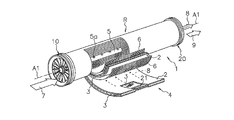
- a spiral membrane element including the center tube 5 and a sealing portion 21 that prevents mixing of the supply side passage and the permeation side passage is used (see Patent Document 1).
- the membrane element 1 When the membrane element 1 is used, the supply liquid 7 is supplied from one end face side of the membrane element 1, and the supplied supply liquid 7 is along the supply-side flow path member 6 in the axial direction A 1 of the central tube 5. And is discharged as a concentrate 9 from the other end face side of the membrane element 1.
- the permeated liquid 8 that has permeated the composite semipermeable membrane 2 in the process in which the supply liquid 7 flows along the supply-side flow path material 6 opens the opening 5a along the permeation-side flow path material 3 as shown by the broken line arrows in the figure. From the end of the central tube 5 and out of the membrane element 1.
- Patent Document 2 for example, as a permeate-side flow path material of a spiral membrane element, a resin is applied to a tricot knitted fabric in consideration of securing a flow path in the permeate-side flow path and pressure loss. What has been impregnated to increase rigidity has been used. Further, according to this document, it is preferable that the width of the groove formed on the surface of the tricot knitted fabric is 0.5 to 0.9 mm in order to reduce the pressure loss of the permeation side flow path.
- the flow rate of the permeate flowing through the permeate side channel formed by the permeate side channel material can be reduced simply by reducing the groove width of the permeate side channel material. It turned out to be smaller.
- an object of the present invention is to increase the effective membrane area of the composite semipermeable membrane, and to reduce the blocking rate due to deformation of the composite semipermeable membrane while ensuring a sufficient flow rate of the permeate flowing through the permeate side flow path.
- An object of the present invention is to provide a spiral membrane element that can be suppressed.
- the spiral membrane element of the present invention comprises a laminate comprising a composite semipermeable membrane having a separation functional layer on the surface of a porous support, a supply-side channel material and a permeation-side channel material, and the laminate is wound.
- the thickness of the porous support of the composite semipermeable membrane is as follows: 70 to 120 ⁇ m
- the permeate-side channel material is formed of a tricot knitted fabric having a plurality of ridges formed by loops that are linearly repeated in the longitudinal direction and a plurality of grooves existing between the ridges.
- the membrane support index calculated from the number of grooves formed per 25 mm (wall) ⁇ ⁇ gutter width (mm) / groove width (mm) ⁇ is 60 to 135, and ⁇ groove width (mm) ⁇ groove depth ( mm) x number of grooves per 25 mm (wall) ⁇ / 25 mm Channel index is calculated from the number (course) of the loops forming the Rinose, characterized in that it is 0.18 ⁇ 0.45 (mm 2).
- the membrane support index reflecting the ratio of the number of ridges supporting the membrane and the ridge width is 60 or more, even when the composite semipermeable membrane is made thinner than before, the composite It is possible to suppress a decrease in the rejection rate caused by repeated deformation of the semipermeable membrane. Further, since the membrane support index is 135 or less, a sufficient flow rate of the permeate flowing through the permeate-side flow path can be secured.
- the flow path index reflecting the total cross-sectional area of the flow path and the resistance due to the loop is 0.18 (mm 2 ) or more, the flow rate of the permeate can be sufficiently secured, and the flow path index is Since it is 0.45 (mm ⁇ 2 >) or less, the repeated deformation
- the thickness of the permeate side channel material is 0.10 to 0.40 mm. With such a thickness of the permeation-side flow path material, it is possible to sufficiently secure the permeation-side flow path and sufficiently ensure the effective membrane area of the composite semipermeable membrane in the spiral membrane element.
- the groove width of the permeate side channel material is preferably 0.10 to 0.30 mm. With such a groove width, it becomes easy to obtain a tricot knitted fabric within the range of the membrane support index and the flow path index, and in combination with the membrane support index and the flow path index, more reliably It is possible to suppress a decrease in the rejection rate due to the deformation of the composite semipermeable membrane while ensuring a sufficient flow rate.
- the porous support preferably has a polymer porous layer having a thickness of 10 to 35 ⁇ m on one side of a nonwoven fabric layer having a thickness of 50 to 90 ⁇ m.
- the permeate side channel material is a tricot knitted fabric that has been subjected to resin reinforcement or fusion treatment after the formation of the knitted fabric.
- resin reinforcement or fusion treatment after the formation of the knitted fabric.
- the permeate-side channel material is wound in a direction in which a linearly continuous groove is along the circumferential direction.
- FIG. 3 is a partially cutaway perspective view showing an example of a spiral membrane element of the present invention. It is a figure which shows an example of the permeation
- the spiral membrane element of the present invention includes a laminate including a composite semipermeable membrane 2, a supply-side channel material 6, and a permeation-side channel material 3, and a wound body around which the laminate is wound.
- a hole center tube 5 and a sealing portion 21 that prevents mixing of the supply-side flow path and the permeation-side flow path are provided.
- the sealing part 21 for preventing mixing of the supply side flow path and the permeation side flow path is obtained by, for example, superimposing the composite semipermeable membrane 2 on both surfaces of the permeation side flow path material 3 and bonding the three sides.
- the sealing part 21 is formed on the sealing part 21 on the outer peripheral side edge, the upstream side edge, and the downstream side edge.
- the envelope film 4 is attached to the central tube 5 at its opening, and is wound spirally around the outer peripheral surface of the central tube 5 together with the net-like (net-like) supply-side flow path member 6 so that the wound body R becomes It is formed.
- An upstream end member 10 such as a seal carrier is provided on the upstream side of the wound body R, and a downstream end member 20 such as a telescope prevention member is provided on the downstream side as necessary.
- the supply liquid 7 is supplied from one end face side of the membrane element 1.
- the supplied supply liquid 7 flows along the supply-side flow path material 6 in a direction parallel to the axial direction A1 of the central tube 5 and is discharged as a concentrated liquid 9 from the other end face side of the membrane element 1.
- the permeated liquid 8 that has permeated through the composite semipermeable membrane 2 in the process of the supply liquid 7 flowing along the supply-side flow path material 6 is opened along the permeation-side flow path material 3 as shown by the broken line arrows in the figure. It flows into the inside of the central tube 5 from 5a and flows out from the end of the central tube 5.
- the supply-side flow path member 6 generally has a role of ensuring a gap for uniformly supplying fluid to the membrane surface.
- a supply-side flow path member 6 for example, a net, a knitted fabric, a concavo-convex processed sheet or the like can be used, and a material having a maximum thickness of about 0.1 to 3 mm can be used as necessary.
- the pressure loss is low, and further, a material that causes an appropriate turbulent flow effect is preferable.
- the flow path material is installed on both surfaces of the separation membrane, different flow path materials are generally used as the supply side flow path material 6 on the supply liquid side and the permeate side flow path material 3 on the permeate side. It is.
- the supply-side channel material 6 uses a coarse and thick net-like channel material, while the permeate-side channel material 3 uses a fine woven or knitted channel material.
- the supply-side channel material 6 is provided on the inner surface side of the bi-folded composite semipermeable membrane 2 when an RO membrane or NF membrane is used in applications such as seawater desalination and wastewater treatment.
- the material to be constructed is not particularly limited, but polyethylene or polypropylene is used. These resins may contain bactericides and antibacterial agents.
- the thickness of the supply side channel material 6 is generally 0.2 to 2.0 mm, preferably 0.5 to 1.0 mm. If the thickness is too thick, the amount of permeation decreases with the amount of film that can be accommodated in the element. Conversely, if the thickness is too thin, contaminants tend to adhere, and the permeation performance is likely to deteriorate.
- the supply side channel material 6 having a thickness of 0.9 to 1.3 mm, contaminants are less likely to accumulate and biofouling is less likely to occur. The decrease can be suppressed.
- the center tube 12 only needs to have an opening 12a around the tube, and any conventional tube can be used.
- any conventional tube can be used.
- the permeate 8 that has passed through the composite semipermeable membrane 2 flows into the center tube 12 from the opening 5a.
- the length of the central tube 12 is generally longer than the length in the axial direction of the element, but the central tube 12 having a connection structure such as being divided into a plurality of elements may be used.
- a thermosetting resin or a thermoplastic resin is used.
- the spiral membrane element of the present invention may be trimmed at both ends of the wound body R after resin sealing in order to adjust the length in the axial direction A1. Further, a perforated end member for preventing deformation (such as a telescope), a sealing material, a reinforcing material, an exterior material, and the like can be provided as necessary.
- the thickness of the porous support of the composite semipermeable membrane having a separation functional layer on the surface of the porous support is 70 to 120 ⁇ m
- the permeate-side channel material is a tricot knitted fabric having a membrane support index and a channel index within a predetermined range.
- the permeate side channel material is used for the permeation side of the composite semipermeable membrane (on the side of the porous support opposite to the separation functional layer) when RO membranes or NF membranes are used in applications such as seawater desalination and wastewater treatment. ).
- This permeation side channel material is required to support the pressure applied to the membrane from the back side of the membrane and secure a permeate channel.
- the permeate-side flow path material 3 is formed of a tricot knitted fabric.
- the tricot knitted fabric include a single denby knitted fabric, a double denby knitted fabric, a single atlas knitted fabric, a single cord knitted fabric, a double cord knitted fabric (also simply referred to as a cord knitted fabric), and the like in the present invention.
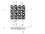
- FIG. 2B schematically shows the relationship between the loop 3a and the diagonal thread 3d.
- a tricot knitted fabric that has been subjected to resin reinforcement or fusion treatment after the formation of the knitted fabric is particularly preferable.
- These tricot knitted fabrics for example, a cord knitted fabric shown in FIGS. 2 (a) to 2 (b), are each a plurality of ridges 3b formed by a loop 3a that repeats linearly in the longitudinal direction, and the ridges 3b And a plurality of grooves 3c existing between them.
- At the bottom of the groove 3c there is an oblique thread 3d for connecting the warp thread from one loop 3a to the next loop 3a. That is, one warp is composed of a loop 3a portion and a diagonal yarn 3d portion.
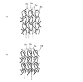
- FIG. 3 shows another example of the permeation-side channel material, where (a) shows an example of a Denby knitted fabric (closed eye), and (b) shows an example of a Denby knitted fabric (opened eye). Yes.
- These examples also include a plurality of ridges 3b formed by loops 3a that are linearly repeated in the vertical direction, and a plurality of grooves 3c that exist between the ridges 3b. At the bottom of the groove 3c, there is an oblique thread 3d for connecting the warp thread from one loop 3a to the next loop 3a. That is, one warp is composed of a loop 3a portion and a diagonal yarn 3d portion.
- the permeation-side channel material 3 in the present invention has a membrane support index of 60 to 135 calculated from the number of grooves per 25 mm (wall) ⁇ ⁇ width Wb (mm) / groove width Wc (mm) ⁇ .
- the membrane support index is preferably from 64 to 133, more preferably from 70 to 120.
- the groove width Wc in the tricot knitted fabric indicates an average value of the widest portion and the narrowest portion between the adjacent loops 3a.
- the average value of the widest part and the narrowest part of the adjacent loops 3a is measured, and this is measured for 10 sets of loop pairs. Seeking.
- the dimensions are obtained from the shape including the thickness of the resin existing on the surface of the loop 3a (the same applies to the following dimensions).
- the heel width Wb refers to the average value of the widest portion of the loop 3a and the portion having the narrowest interval.
- an average value of the widest portion and the narrowest portion of the loop 3a is measured from the optical micrograph, and this is measured for 10 pairs of loops to obtain the average value.
- the permeation side flow path member 3 in the present invention has ⁇ groove width Wc (mm) ⁇ groove depth D (mm) ⁇ number of grooves per 25 mm (wall) ⁇ / loop 3 a forming ridges 3 b per 25 mm.
- the channel index calculated from the number (course) is 0.18 to 0.45 (mm 2 ), and the channel index is 0.20 to 0.40 (mm 2 ). Is more preferable, and 0.22 to 0.35 (mm 2 ) is more preferable.
- the groove depth D in the tricot knitted fabric refers to the height from the surface of the diagonal thread 3d existing between the adjacent loops 3a to the highest portion of the loop 3a.
- the height from the surface of the diagonal thread 3d to the highest portion of the loop 3a is measured for 10 loop pairs from an optical micrograph, and the average value thereof is obtained.
- the groove width Wc in the tricot knitted fabric is preferably 0.05 to 0.40 mm, more preferably 0.10 to 0.28 mm. Further, the number of grooves per 25 mm (wall) is preferably 40 to 60, and the collar width Wb is preferably 0.2 to 0.4 mm.
- the groove depth D in the tricot knitted fabric is preferably 0.10 to 0.15 mm, and the number of loops 3a forming the heel 3b per 25 mm is preferably 40 to 55.
- the thickness of the permeate side channel material is preferably 0.10 to 0.40 mm, more preferably 0.15 to 0.35 mm, and still more preferably 0.20 to 0.30 mm.
- the thickness is less than 0.10 mm, there is a problem that it is difficult to secure a sufficient flow path and the pressure loss of the permeate increases.
- the thickness exceeds 0.40 mm, the effective membrane area of the composite semipermeable membrane in the membrane element becomes small, and there arises a problem that the flow rate of the permeate decreases.
- the constituent yarn of the permeate side channel member preferably has a diameter of 0.1 to 0.15 mm.
- the membrane support index, and the flow path index can be adjusted by the knitting type, the setting of the wall and course, the yarn diameter, the tension at the time of weaving, etc. when manufacturing the tricot knitted fabric.
- constituent thread of the permeate side channel material examples include polyesters such as polyethylene terephthalate and polyethylene naphthalate, and polyolefins such as polyethylene and polypropylene. Of these, polyethylene terephthalate is particularly preferably used from the viewpoint of processability and productivity.
- resin reinforcement is performed after the formation of the knitted fabric, there are a method of impregnating the resin in the fiber and curing it, or a method of coating the resin on the fiber surface and curing.
- the resin used for reinforcement include melamine resin and epoxy resin.
- the constituent yarn of the permeate-side channel material may be a monofilament or a multifilament, but a tricot knitted fabric is formed by the constituent yarn of a certain thickness.
- a tricot knitted fabric is formed by the constituent yarn of a certain thickness.
- cord knitted fabrics having a clear linear groove structure are preferable.
- the direction in which the permeate-side channel material is arranged in the membrane element may be any, but it is preferable that the direction of the continuous groove is wound in a direction along the circumferential direction.
- the composite semipermeable membrane in the present invention has a separation functional layer on the surface of a porous support, and the porous support preferably has a polymer porous layer on one side of a nonwoven fabric layer.
- the thickness of the porous support is preferably 70 to 120 ⁇ m, and more preferably 80 to 100 ⁇ m.
- the thickness of the composite semipermeable membrane is preferably 70 to 125 ⁇ m, more preferably 80 to 105 ⁇ m.
- Such composite semipermeable membranes are called RO (reverse osmosis) membranes, NF (nanofiltration) membranes, and FO (forward osmosis) membranes depending on their filtration performance and treatment method, and they are used for ultrapure water production and seawater desalination. It can be used for desalination of brine, reuse of waste water, etc.
- the separation function layer examples include polyamide, cellulose, polyether, and silicon separation function layers, and those having a polyamide separation function layer are preferable.
- the polyamide-based separation functional layer is generally a homogeneous membrane having no visible pores and has a desired ion separation ability.
- the separation functional layer is not particularly limited as long as it is a polyamide-based thin film that is difficult to peel off from the polymer porous layer.
- a polyfunctional amine component and a polyfunctional acid halide component are formed on the porous support membrane.
- a polyamide-based separation functional layer obtained by interfacial polymerization is well known.
- Such a polyamide-based separation functional layer is known to have a pleated microstructure, and the thickness of this layer is not particularly limited, but is about 0.05 to 2 ⁇ m, preferably 0.1 to 1 ⁇ m. It is known that if this layer is too thin, film surface defects are likely to occur, and if it is too thick, the transmission performance deteriorates.
- the method for forming the polyamide-based separation functional layer on the surface of the polymer porous layer is not particularly limited, and any known method can be used. Examples of the method include an interfacial polymerization method, a phase separation method, and a thin film coating method. In the present invention, the interfacial polymerization method is particularly preferably used. In the interfacial polymerization method, for example, the polymer porous layer is coated with a polyfunctional amine component-containing amine aqueous solution, and then an organic solution containing a polyfunctional acid halide component is brought into contact with the amine aqueous solution-coated surface to cause interfacial polymerization. This is a method for forming a skin layer.
- a removal method a method of inclining a target film, a method of blowing off a gas, a rubber, For example, a method of scraping off a blade by contacting the blade is preferably used.
- the time required for the aqueous amine solution and the organic solution to contact is approximately 1 to 120 seconds, although it depends on the composition of the aqueous amine solution, the viscosity, and the pore diameter of the surface of the porous support membrane. Is about 2 to 40 seconds. If the interval is too long, the aqueous amine solution may permeate and diffuse deep inside the porous support membrane, and a large amount of unreacted polyfunctional amine component may remain in the porous support membrane, resulting in problems. . When the application interval of the solution is too short, an excessive amine aqueous solution remains, so that the film performance tends to be lowered.
- the heating temperature is more preferably 70 to 200 ° C., particularly preferably 80 to 130 ° C.
- the heating time is preferably about 30 seconds to 10 minutes, more preferably about 40 seconds to 7 minutes.
- the polyfunctional amine component contained in the amine aqueous solution is a polyfunctional amine having two or more reactive amino groups, and examples thereof include aromatic, aliphatic, and alicyclic polyfunctional amines.
- the aromatic polyfunctional amine include m-phenylenediamine, p-phenylenediamine, o-phenylenediamine, 1,3,5-triaminobenzene, 1,2,4-triaminobenzene, 3,5- Examples thereof include diaminobenzoic acid, 2,4-diaminotoluene, 2,6-diaminotoluene, N, N′-dimethyl-m-phenylenediamine, 2,4-diaminoanisole, amidol, xylylenediamine and the like.
- Examples of the aliphatic polyfunctional amine include ethylenediamine, propylenediamine, tris (2-aminoethyl) amine, and n-phenyl-ethylenediamine.
- Examples of the alicyclic polyfunctional amine include 1,3-diaminocyclohexane, 1,2-diaminocyclohexane, 1,4-diaminocyclohexane, piperazine, 2,5-dimethylpiperazine, 4-aminomethylpiperazine and the like. It is done. These polyfunctional amines may be used alone or in combination of two or more.
- m-phenylenediamine when a high rejection is required for reverse osmosis membrane performance, it is preferable to use m-phenylenediamine as a main component, which can provide a highly dense separation function layer, and high flux retention in NF membrane performance.
- piperazine when determining the rate, it is preferable to use piperazine as the main component.
- the polyfunctional acid halide component contained in the organic solution is a polyfunctional acid halide having two or more reactive carbonyl groups, and examples thereof include aromatic, aliphatic, and alicyclic polyfunctional acid halides.
- aromatic polyfunctional acid halide include trimesic acid trichloride, terephthalic acid dichloride, isophthalic acid dichloride, biphenyldicarboxylic acid dichloride, naphthalene dicarboxylic acid dichloride, benzenetrisulfonic acid trichloride, benzenedisulfonic acid dichloride, and chlorosulfonylbenzene.
- dicarboxylic acid dichloride dicarboxylic acid dichloride.
- Examples of the aliphatic polyfunctional acid halide include propanedicarboxylic acid dichloride, butanedicarboxylic acid dichloride, pentanedicarboxylic acid dichloride, propanetricarboxylic acid trichloride, butanetricarboxylic acid trichloride, pentanetricarboxylic acid trichloride, glutaryl halide, azide. Poil halide etc. are mentioned.
- Examples of the alicyclic polyfunctional acid halide include cyclopropane tricarboxylic acid trichloride, cyclobutane tetracarboxylic acid tetrachloride, cyclopentane tricarboxylic acid trichloride, cyclopentane tetracarboxylic acid tetrachloride, cyclohexane tricarboxylic acid trichloride, and tetrahydro Examples include furantetracarboxylic acid tetrachloride, cyclopentanedicarboxylic acid dichloride, cyclobutanedicarboxylic acid dichloride, cyclohexanedicarboxylic acid dichloride, and tetrahydrofurandicarboxylic acid dichloride.
- polyfunctional acid halides may be used alone or in combination of two or more.
- an aromatic polyfunctional acid halide it is preferable to use an aromatic polyfunctional acid halide.
- the concentration of the polyfunctional amine component in the aqueous amine solution is not particularly limited, but is preferably 0.1 to 7% by weight, more preferably 1 to 5% by weight. If the concentration of the polyfunctional amine component is too low, defects are likely to occur in the skin layer, and the salt blocking performance tends to be reduced. On the other hand, when the concentration of the polyfunctional amine component is too high, it becomes too thick and the permeation flux tends to decrease.
- the concentration of the polyfunctional acid halide component in the organic solution is not particularly limited, but is preferably 0.01 to 5% by weight, more preferably 0.05 to 3% by weight. If the concentration of the polyfunctional acid halide component is too low, the unreacted polyfunctional amine component is increased, and defects are likely to occur in the skin layer. On the other hand, if the concentration of the polyfunctional acid halide component is too high, the amount of unreacted polyfunctional acid halide component increases, so that the skin layer becomes too thick and the permeation flux tends to decrease.
- the organic solvent containing the polyfunctional acid halide is not particularly limited as long as it has low solubility in water and does not deteriorate the porous support membrane, and can dissolve the polyfunctional acid halide component.
- cyclohexane examples thereof include saturated hydrocarbons such as heptane, octane and nonane, and halogen-substituted hydrocarbons such as 1,1,2-trichlorotrifluoroethane.
- Preferred is a saturated hydrocarbon having a boiling point of 300 ° C. or lower, more preferably a boiling point of 200 ° C. or lower.
- the additive may add the additive for the purpose of the improvement of various performance and a handleability to the said amine aqueous solution and organic solution.
- the additive include polymers such as polyvinyl alcohol, polyvinyl pyrrolidone and polyacrylic acid, polyhydric alcohols such as sorbitol and glycerin, and surfactants such as sodium dodecylbenzenesulfonate, sodium dodecylsulfate, and sodium laurylsulfate.
- Basic compounds such as sodium hydroxide, trisodium phosphate and triethylamine for removing hydrogen halide produced by polymerization, acylation catalysts, and solubility parameters described in JP-A-8-224452 are 8 to 14 (cal / Cm 3 ) 1/2 compound and the like.
- a coating layer composed of various polymer components may be provided on the exposed surface of the separation functional layer.
- the polymer component is not particularly limited as long as it does not dissolve the separation functional layer and the porous support membrane and does not elute during the water treatment operation.
- polyvinyl alcohol, polyvinyl pyrrolidone, hydroxypropyl cellulose, polyethylene And glycols and saponified polyethylene-vinyl acetate copolymers may be provided on the exposed surface of the separation functional layer.
- the polymer component is not particularly limited as long as it does not dissolve the separation functional layer and the porous support membrane and does not elute during the water treatment operation.
- polyvinyl alcohol polyvinyl pyrrolidone
- hydroxypropyl cellulose polyethylene And glycols
- saponified polyethylene-vinyl acetate copolymers saponified polyethylene-vinyl acetate copolymers.
- polyvinyl alcohol in particular, by using polyvinyl alcohol having a saponification degree of 99% or more, or by crosslinking polyvinyl alcohol having a saponification degree of 90% or more with the polyamide-based resin of the skin layer, It is preferable to use a structure that does not easily dissolve during water treatment.
- the charge state of the film surface is adjusted and hydrophilicity is imparted, so that the adhesion of contaminants can be suppressed, and further, the flux retention effect is achieved by a synergistic effect with the present invention. Can be further enhanced.
- the nonwoven fabric layer used in the present invention is not particularly limited as long as it imparts appropriate mechanical strength while maintaining the separation performance and permeation performance of the composite semipermeable membrane, and a commercially available nonwoven fabric is used. be able to.
- a material made of polyolefin, polyester, cellulose or the like is used, and a material in which a plurality of materials are mixed can also be used.
- polyester in terms of moldability.
- a long fiber nonwoven fabric or a short fiber nonwoven fabric can be used as appropriate, but a long fiber nonwoven fabric can be preferably used from the viewpoint of fine fuzz that causes pinhole defects and uniformity of the film surface.
- the air permeability of the nonwoven fabric layer at this time is not limited to this, but it can be about 0.5 to 10 cm 3 / cm 2 ⁇ s, and 1 to 5 cm 3 / s. Those having a size of about cm 2 ⁇ s are preferably used.
- the thickness of the nonwoven fabric layer is preferably 90 ⁇ m or less, more preferably 80 ⁇ m or less, and particularly preferably 70 ⁇ m or less. If this thickness is too thick, the permeation resistance becomes too high and the flux tends to decrease. On the other hand, if it is too thin, the mechanical strength as a composite semipermeable membrane support will decrease, making it difficult to obtain a stable composite semipermeable membrane. Therefore, 50 ⁇ m or more is preferable, and 55 ⁇ m or more is more preferable.
- the polymer porous layer is not particularly limited as long as it can form the polyamide-based separation functional layer, but is usually a microporous layer having a pore diameter of about 0.01 to 0.4 ⁇ m.
- the material for forming the microporous layer may include various materials such as polysulfone, polyarylethersulfone exemplified by polyethersulfone, polyimide, and polyvinylidene fluoride.
- the thickness of the polymer porous layer is preferably 35 ⁇ m or less, and more preferably 32 ⁇ m or less. It has been found that if it is too thick, the flux retention after pressurization tends to decrease. Furthermore, it is particularly preferably 29 ⁇ m or less, and most preferably 26 ⁇ m or less. By forming the thin film to this extent, the stability of the flux retention rate can be further increased. Moreover, since it will become easy to produce a defect when it is too thin, 10 micrometers or more are preferable and 15 micrometers or more are more preferable.
- the polymer porous layer can be produced by a method generally called a wet method or a dry wet method.
- a solution preparation step in which polysulfone, a solvent and various additives are dissolved
- a coating step in which the nonwoven fabric is coated with the solution
- a drying step in which the solvent in the solution is evaporated to cause microphase separation, a water bath, etc.
- the polymer porous layer on the nonwoven fabric can be formed through an immobilization step of immobilization by dipping in a coagulation bath.
- the thickness of the polymer porous layer can be set by adjusting the solution concentration and the coating amount after calculating the ratio of impregnation into the nonwoven fabric layer.
- the spiral membrane element of the present invention can be used for applications such as seawater desalination and wastewater treatment. However, in recent years, in order to reduce power consumption during operation, it is a composite that can obtain a sufficient permeation flux even at a lower pressure than before. Semipermeable membranes have been developed. In an application using such a composite semipermeable membrane, for example, 0.3 to 3.0 MPa is set as the differential pressure (operating pressure) between the supply side and the permeation side of the membrane, and preferably 0.5 to 1.5 MPa. Is set.
- the spiral membrane element of the present invention can cope with the reduction of the thickness of the porous support by using a permeate-side flow path material having a higher density than before even when operating at such a low pressure. It is.
- the thickness was measured using a commercially available thickness measuring instrument (Ozaki Mfg. Co., Ltd .: Dial Thickness Gauge G-7C).
- the thickness of the nonwoven fabric layer is measured in advance, and the thickness of the entire composite semipermeable membrane support is formed with the polymer porous layer formed on the nonwoven fabric layer.
- the difference between the thickness of the composite semipermeable membrane support and the thickness of the non-woven fabric was determined to obtain the thickness of the polymer porous layer.
- an average value of arbitrary ten points measured values on the same film surface was used.
- the produced flat membrane-shaped composite semipermeable membrane is cut into a predetermined shape and size, and is set in a cell for flat membrane evaluation together with various permeation side flow path materials.
- An On-Off cycle of “pressurizing to 4 MPa and returning to 0 MPa” is repeated 200 times using a 1500 mg / L NaCl aqueous solution as a supply liquid.
- an aqueous solution containing NaCl having a concentration of 1500 mg / L was brought into contact with the membrane by applying a pressure of 1.05 MPa to the membrane supply side at 25 ° C.
- the NaCl concentration in the membrane permeate is measured from the conductivity of the permeate.
- Durability was evaluated by determining the ratio between the salt permeability (SP) after 200 pressurization and the salt permeability of the membrane (before pressurization) by the following formula.
- transmission side flow path material was arrange
- Salt permeability (SP) (%) (NaCl concentration in membrane permeate / NaCl concentration in feed solution) ⁇ 100 (Water permeability)
- Production Example 1 Production of composite semipermeable membrane
- a commercially available non-woven fabric made of polyester for water treatment membrane support width: approx. 1 m
- a mixed solution of polysulfone and dimethylformamide polymer concentration 18.35% by weight
- a long porous support thickness: 90 ⁇ m
- a polymer porous layer having a thickness of 25 ⁇ m was formed was prepared by coagulation treatment in 35 ° C. water.
- the surface of the polymer porous layer was contacted with a solution A in which 3% by weight of m-phenylenediamine and 0.15% by weight of sodium lauryl sulfate were mixed, and then the excess solution A was added. Removed to form a coating layer of solution A. Next, a solution B containing 0.3% by weight of trimesic acid chloride in a hexane solvent was brought into contact with the surface of the solution A coating layer. Then, the separation functional layer was formed by drying in an environment of 120 ° C. to obtain a long composite semipermeable membrane.
- Production Example 2 (Production of composite semipermeable membrane)
- a non-woven fabric having a thickness of 90 ⁇ m was used to form a polymer porous layer having a thickness of 40 ⁇ m, and a porous support having a thickness of 130 ⁇ m was obtained.
- a composite semipermeable membrane was prepared.
- Comparative Examples 1 to 4 Durability and water permeability were evaluated using the composite semipermeable membrane obtained in Production Example 1 and the permeation side channel materials A to D shown in Table 1. The results are also shown in Table 1.
- Example 5 In Example 1, in place of the composite semipermeable membrane obtained in Production Example 1, the composite semipermeable membrane obtained in Production Example 2 (porous support thickness 130 ⁇ m) was used. The durability was evaluated under exactly the same conditions. As a result, the durability becomes 2.1, and the pressure resistance improves as the film thickness increases compared to Example 1, but the effective membrane area when the spiral membrane element is filled with the composite semipermeable membrane is Since it decreases by 16% compared with Example 1, the flow rate of the membrane element decreases, which is not desirable.
Landscapes
- Chemical & Material Sciences (AREA)
- Chemical Kinetics & Catalysis (AREA)
- Life Sciences & Earth Sciences (AREA)
- Hydrology & Water Resources (AREA)
- Engineering & Computer Science (AREA)
- Environmental & Geological Engineering (AREA)
- Water Supply & Treatment (AREA)
- Organic Chemistry (AREA)
- Separation Using Semi-Permeable Membranes (AREA)
Priority Applications (4)
| Application Number | Priority Date | Filing Date | Title |
|---|---|---|---|
| EP16881632.0A EP3417928B1 (en) | 2015-12-28 | 2016-12-14 | Spiral membrane element |
| KR1020187014858A KR102035951B1 (ko) | 2015-12-28 | 2016-12-14 | 스파이럴형 막 엘리먼트 |
| CN201680072444.3A CN108367248B (zh) | 2015-12-28 | 2016-12-14 | 螺旋型膜元件 |
| US16/063,981 US10974200B2 (en) | 2015-12-28 | 2016-12-14 | Spiral membrane element |
Applications Claiming Priority (2)
| Application Number | Priority Date | Filing Date | Title |
|---|---|---|---|
| JP2015-256511 | 2015-12-28 | ||
| JP2015256511A JP6347775B2 (ja) | 2015-12-28 | 2015-12-28 | スパイラル型膜エレメント |
Publications (1)
| Publication Number | Publication Date |
|---|---|
| WO2017115653A1 true WO2017115653A1 (ja) | 2017-07-06 |
Family
ID=59225139
Family Applications (1)
| Application Number | Title | Priority Date | Filing Date |
|---|---|---|---|
| PCT/JP2016/087205 WO2017115653A1 (ja) | 2015-12-28 | 2016-12-14 | スパイラル型膜エレメント |
Country Status (6)
Cited By (1)
| Publication number | Priority date | Publication date | Assignee | Title |
|---|---|---|---|---|
| WO2018052124A1 (ja) * | 2016-09-16 | 2018-03-22 | 日東電工株式会社 | スパイラル型膜エレメント |
Families Citing this family (3)
| Publication number | Priority date | Publication date | Assignee | Title |
|---|---|---|---|---|
| GB201912458D0 (en) * | 2019-08-30 | 2019-10-16 | Fujifilm Mfg Europe Bv | Gas seperations elements and modules |
| JP7715577B2 (ja) * | 2021-08-27 | 2025-07-30 | Kbセーレン株式会社 | 液体分離装置用流路材 |
| JP7072112B1 (ja) * | 2021-11-05 | 2022-05-19 | 日東電工株式会社 | 複合半透膜、スパイラル型膜エレメント、水処理システム及び水処理方法 |
Citations (9)
| Publication number | Priority date | Publication date | Assignee | Title |
|---|---|---|---|---|
| JPH09276671A (ja) * | 1996-04-11 | 1997-10-28 | Toray Ind Inc | 液体分離素子、装置および処理方法 |
| JP2000051668A (ja) * | 1999-08-24 | 2000-02-22 | Toray Ind Inc | 液体分離素子および造水方法 |
| JP2000342941A (ja) * | 1999-06-08 | 2000-12-12 | Nitto Denko Corp | 液体分離膜モジュール |
| JP2007167783A (ja) * | 2005-12-22 | 2007-07-05 | Nitto Denko Corp | スパイラル型分離膜エレメント |
| WO2007114069A1 (ja) * | 2006-03-31 | 2007-10-11 | Toray Industries, Inc. | 液体分離素子、流路材およびその製造方法 |
| JP2010131483A (ja) * | 2008-12-02 | 2010-06-17 | Kb Seiren Ltd | 液体分離用流路形成材およびその製法 |
| WO2013125583A1 (ja) * | 2012-02-23 | 2013-08-29 | 東レ株式会社 | 分離膜支持体とその製造方法、ならびに分離膜支持体を用いた分離膜および流体分離素子 |
| JP2015205269A (ja) * | 2014-04-08 | 2015-11-19 | 東レ株式会社 | 分離膜構造体および分離膜エレメント |
| JP2017000939A (ja) * | 2015-06-09 | 2017-01-05 | 東レ株式会社 | トリコット流路材 |
Family Cites Families (8)
| Publication number | Priority date | Publication date | Assignee | Title |
|---|---|---|---|---|
| US4933083A (en) * | 1985-04-15 | 1990-06-12 | Hoechst Celanese Corp. | Polybenzimidazole thin film composite membranes |
| JPH0771623B2 (ja) | 1985-09-09 | 1995-08-02 | 株式会社日立製作所 | スパイラル型膜エレメント |
| US5721910A (en) | 1996-06-04 | 1998-02-24 | Exxon Research And Engineering Company | Relational database system containing a multidimensional hierachical model of interrelated subject categories with recognition capabilities |
| JPH10137558A (ja) | 1996-11-11 | 1998-05-26 | Nitto Denko Corp | スパイラル型分離膜エレメントおよびその製造方法 |
| US6036739A (en) * | 1997-02-03 | 2000-03-14 | New, Sr.; Curry W. | Knitted felt filtration media |
| JP3801783B2 (ja) | 1998-07-16 | 2006-07-26 | 本田技研工業株式会社 | 休筒式エンジンの制御装置 |
| EP1059114B1 (en) | 1999-06-08 | 2005-10-12 | Nitto Denko Corporation | Liquid separation membrane module and method of producing the same |
| JP2014522294A (ja) * | 2011-04-13 | 2014-09-04 | ジーエフディー ファブリックス,インク. | 流体ろ過システムのフィルターエレメント |
-
2015
- 2015-12-28 JP JP2015256511A patent/JP6347775B2/ja active Active
-
2016
- 2016-12-14 US US16/063,981 patent/US10974200B2/en active Active
- 2016-12-14 CN CN201680072444.3A patent/CN108367248B/zh active Active
- 2016-12-14 WO PCT/JP2016/087205 patent/WO2017115653A1/ja active Application Filing
- 2016-12-14 KR KR1020187014858A patent/KR102035951B1/ko active Active
- 2016-12-14 EP EP16881632.0A patent/EP3417928B1/en not_active Not-in-force
Patent Citations (9)
| Publication number | Priority date | Publication date | Assignee | Title |
|---|---|---|---|---|
| JPH09276671A (ja) * | 1996-04-11 | 1997-10-28 | Toray Ind Inc | 液体分離素子、装置および処理方法 |
| JP2000342941A (ja) * | 1999-06-08 | 2000-12-12 | Nitto Denko Corp | 液体分離膜モジュール |
| JP2000051668A (ja) * | 1999-08-24 | 2000-02-22 | Toray Ind Inc | 液体分離素子および造水方法 |
| JP2007167783A (ja) * | 2005-12-22 | 2007-07-05 | Nitto Denko Corp | スパイラル型分離膜エレメント |
| WO2007114069A1 (ja) * | 2006-03-31 | 2007-10-11 | Toray Industries, Inc. | 液体分離素子、流路材およびその製造方法 |
| JP2010131483A (ja) * | 2008-12-02 | 2010-06-17 | Kb Seiren Ltd | 液体分離用流路形成材およびその製法 |
| WO2013125583A1 (ja) * | 2012-02-23 | 2013-08-29 | 東レ株式会社 | 分離膜支持体とその製造方法、ならびに分離膜支持体を用いた分離膜および流体分離素子 |
| JP2015205269A (ja) * | 2014-04-08 | 2015-11-19 | 東レ株式会社 | 分離膜構造体および分離膜エレメント |
| JP2017000939A (ja) * | 2015-06-09 | 2017-01-05 | 東レ株式会社 | トリコット流路材 |
Non-Patent Citations (1)
| Title |
|---|
| See also references of EP3417928A4 * |
Cited By (8)
| Publication number | Priority date | Publication date | Assignee | Title |
|---|---|---|---|---|
| WO2018052124A1 (ja) * | 2016-09-16 | 2018-03-22 | 日東電工株式会社 | スパイラル型膜エレメント |
| WO2018052122A1 (ja) * | 2016-09-16 | 2018-03-22 | 日東電工株式会社 | スパイラル型膜エレメント |
| JP2018047455A (ja) * | 2016-09-16 | 2018-03-29 | 日東電工株式会社 | スパイラル型膜エレメント |
| JP2018047456A (ja) * | 2016-09-16 | 2018-03-29 | 日東電工株式会社 | スパイラル型膜エレメント |
| US10987632B2 (en) | 2016-09-16 | 2021-04-27 | Nitto Denko Corporation | Spiral membrane element |
| JP7037306B2 (ja) | 2016-09-16 | 2022-03-16 | 日東電工株式会社 | スパイラル型膜エレメント |
| JP7089352B2 (ja) | 2016-09-16 | 2022-06-22 | 日東電工株式会社 | スパイラル型膜エレメント |
| US11433356B2 (en) | 2016-09-16 | 2022-09-06 | Nitto Denko Corporation | Spiral membrane element |
Also Published As
| Publication number | Publication date |
|---|---|
| EP3417928A4 (en) | 2019-11-20 |
| CN108367248B (zh) | 2021-04-23 |
| KR20180074770A (ko) | 2018-07-03 |
| JP2017119238A (ja) | 2017-07-06 |
| US20190001274A1 (en) | 2019-01-03 |
| EP3417928B1 (en) | 2021-09-22 |
| KR102035951B1 (ko) | 2019-10-23 |
| EP3417928A1 (en) | 2018-12-26 |
| JP6347775B2 (ja) | 2018-06-27 |
| CN108367248A (zh) | 2018-08-03 |
| US10974200B2 (en) | 2021-04-13 |
Similar Documents
| Publication | Publication Date | Title |
|---|---|---|
| JP7037306B2 (ja) | スパイラル型膜エレメント | |
| JP6305729B2 (ja) | 複合半透膜 | |
| WO2016047696A1 (ja) | スパイラル型膜エレメント | |
| WO2017115653A1 (ja) | スパイラル型膜エレメント | |
| JP6522185B2 (ja) | 複合半透膜 | |
| WO2016035681A1 (ja) | 複合半透膜、分離膜エレメント、及びその製造方法 |
Legal Events
| Date | Code | Title | Description |
|---|---|---|---|
| 121 | Ep: the epo has been informed by wipo that ep was designated in this application |
Ref document number: 16881632 Country of ref document: EP Kind code of ref document: A1 |
|
| ENP | Entry into the national phase |
Ref document number: 20187014858 Country of ref document: KR Kind code of ref document: A |
|
| NENP | Non-entry into the national phase |
Ref country code: DE |
|
| WWE | Wipo information: entry into national phase |
Ref document number: 2016881632 Country of ref document: EP |
|
| ENP | Entry into the national phase |
Ref document number: 2016881632 Country of ref document: EP Effective date: 20180730 |