WO2017111101A1 - 回転電機の制御装置、作業機械及び回転電機の制御方法 - Google Patents
回転電機の制御装置、作業機械及び回転電機の制御方法 Download PDFInfo
- Publication number
- WO2017111101A1 WO2017111101A1 PCT/JP2016/088519 JP2016088519W WO2017111101A1 WO 2017111101 A1 WO2017111101 A1 WO 2017111101A1 JP 2016088519 W JP2016088519 W JP 2016088519W WO 2017111101 A1 WO2017111101 A1 WO 2017111101A1
- Authority
- WO
- WIPO (PCT)
- Prior art keywords
- period
- winding
- electric machine
- voltage
- value
- Prior art date
- Legal status (The legal status is an assumption and is not a legal conclusion. Google has not performed a legal analysis and makes no representation as to the accuracy of the status listed.)
- Ceased
Links
Images










Classifications
-
- H—ELECTRICITY
- H02—GENERATION; CONVERSION OR DISTRIBUTION OF ELECTRIC POWER
- H02P—CONTROL OR REGULATION OF ELECTRIC MOTORS, ELECTRIC GENERATORS OR DYNAMO-ELECTRIC CONVERTERS; CONTROLLING TRANSFORMERS, REACTORS OR CHOKE COILS
- H02P25/00—Arrangements or methods for the control of AC motors characterised by the kind of AC motor or by structural details
- H02P25/02—Arrangements or methods for the control of AC motors characterised by the kind of AC motor or by structural details characterised by the kind of motor
- H02P25/08—Reluctance motors
-
- H—ELECTRICITY
- H02—GENERATION; CONVERSION OR DISTRIBUTION OF ELECTRIC POWER
- H02P—CONTROL OR REGULATION OF ELECTRIC MOTORS, ELECTRIC GENERATORS OR DYNAMO-ELECTRIC CONVERTERS; CONTROLLING TRANSFORMERS, REACTORS OR CHOKE COILS
- H02P25/00—Arrangements or methods for the control of AC motors characterised by the kind of AC motor or by structural details
- H02P25/02—Arrangements or methods for the control of AC motors characterised by the kind of AC motor or by structural details characterised by the kind of motor
- H02P25/08—Reluctance motors
- H02P25/092—Converters specially adapted for controlling reluctance motors
-
- H—ELECTRICITY
- H02—GENERATION; CONVERSION OR DISTRIBUTION OF ELECTRIC POWER
- H02P—CONTROL OR REGULATION OF ELECTRIC MOTORS, ELECTRIC GENERATORS OR DYNAMO-ELECTRIC CONVERTERS; CONTROLLING TRANSFORMERS, REACTORS OR CHOKE COILS
- H02P25/00—Arrangements or methods for the control of AC motors characterised by the kind of AC motor or by structural details
- H02P25/02—Arrangements or methods for the control of AC motors characterised by the kind of AC motor or by structural details characterised by the kind of motor
- H02P25/08—Reluctance motors
- H02P25/098—Arrangements for reducing torque ripple
Definitions
- the present invention relates to a control device of a rotating electrical machine, a working machine, and a control method of the rotating electrical machine.
- a switched reluctance motor is known as a three-phase rotary electric machine.
- Patent Document 1 describes a technique for controlling a switched reluctance motor.
- An object of the present invention is to suppress the efficiency decrease and the noise of the rotating electrical machine reliably by simple control regardless of the driving conditions such as the voltage of the DC power supply.
- a first voltage is applied to the winding of each phase of the rotating electric machine to control the rotating electric machine having two or more phases, and a first period during which the flux linkage is increased.
- a second voltage is applied to the winding in the opposite direction to the first voltage after the second period during a second period in which the voltage applied to the winding is set to 0 later and the flux linkage is held.
- the third period in which the flux linkage is reduced, and the fourth period in which the voltage applied to the winding is set to zero from the third period to the first period of the next cycle is one cycle While applying a voltage, the second period is set to a value between the first value and a second value obtained by dividing the one cycle by the number of phases of the rotating electrical machine from the first value. It is a control device of a rotating electrical machine to control.
- the sum of the first period and the second period be the second value.
- the flux linkage at the start of the first period is increased, It is preferable to accelerate the switching from the third period to the fourth period, or to change the end of the third period to the fourth period if the fourth period is zero.
- the present invention is a working machine including a two-phase or more switched reluctance motor that is a two-phase or more rotating electric machine, and the above-described controller for the rotating electric machine.
- a first voltage is applied to the winding of each phase of the rotating electric machine to control the rotating electric machine having two or more phases, and a first period during which the flux linkage is increased.
- a second voltage is applied to the winding in the opposite direction to the first voltage after the second period during a second period in which the voltage applied to the winding is set to 0 later and the flux linkage is held.
- the third period in which the flux linkage is reduced, and the fourth period in which the voltage applied to the winding is set to zero from the third period to the first period of the next cycle is one cycle
- a voltage is applied, and the second period is controlled to a value between a first value and a second value obtained by dividing the one cycle by the number of phases of the rotating electrical machine from the first value. Is a control method of a rotating electrical machine.
- the sum of the first period and the second period be the second value.
- the flux linkage at the start of the first period is increased, It is preferable to accelerate the switching from the third period to the fourth period, or to change the end of the third period to the fourth period if the fourth period is zero.
- the present invention can suppress the efficiency decrease and the noise of the rotating electrical machine reliably by the simple control regardless of the driving condition such as the voltage of the DC power supply.
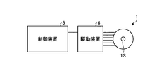
- FIG. 1 is a view showing a two- or more-phase rotary electric machine according to this embodiment and a control device of the rotary electric machine for controlling the same.
- FIG. 2 is a front view showing the rotating electrical machine according to the present embodiment.
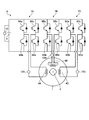
- FIG. 3 is a view showing an example of a drive device according to the present embodiment.
- FIG. 4 is a diagram showing the positional relationship between the stator and the rotor of the rotary electric machine.
- FIG. 5-1 is a diagram for describing an example of control of the control device according to the present embodiment.
- FIG. 5-2 is a diagram for explaining a control example of the control device according to the present embodiment.
- FIG. 6 is a diagram for explaining a control example of the control device according to the present embodiment.
- FIG. 1 is a view showing a two- or more-phase rotary electric machine according to this embodiment and a control device of the rotary electric machine for controlling the same.
- FIG. 2 is a front view showing the rotating electrical machine according to the present embodiment
- FIG. 7 is a diagram for explaining the operation of the drive device that operates based on the command of the control device according to the present embodiment.
- FIG. 8 is a diagram for explaining the operation of the drive device that operates based on the command of the control device according to the present embodiment.
- FIG. 9 is a diagram for explaining the operation of the drive device that operates based on the command of the control device according to the present embodiment.
- FIG. 10 is a view showing an example of a rotation angle at which a torque is easily generated and an example of a rotation angle at which a torque is hardly generated.
- FIG. 11 is a diagram showing an example of the A-phase, B-phase, and C-phase in the control in which the current flowing through the winding becomes a rectangular wave.
- FIG. 12 is a diagram showing an example of the A-phase, B-phase, and C-phase excitation force in the control method of the rotating electrical machine of the present embodiment by the control device.
- FIG. 13 is a view showing an example of the current flowing in each phase when the control device according to the present embodiment controls the rotating electrical machine.
- FIG. 14 is a diagram showing the relationship between the current flowing through the winding and the electrical angle during continuous energization in which the fourth period is zero.
- FIG. 15 is a diagram showing the relationship between the current flowing through the winding and the electrical angle during continuous energization in which the fourth period is zero.
- FIG. 16 is a diagram showing the relationship between the current flowing through the winding and the flux linkage during continuous energization in which the fourth period is zero.
- FIG. 17 is a diagram showing the relationship between the current flowing through the winding and the flux linkage during continuous energization in which the fourth period is zero.
- FIG. 18 is a diagram showing the relationship between the current flowing through the winding in one phase of the rotary electric machine and the electrical angle.
- FIG. 19 is a diagram showing the relationship between the electrical angle and the current flowing through the A-phase, B-phase, and C-phase windings of the rotary electric machine.
- FIG. 20 is a diagram showing an example of the result when torque is changed while keeping the rotational speed of the rotating electrical machine constant, by the relationship between the flux linkage at the midpoint of the reflux and the current flowing through the winding.
- FIG. 21 is a view showing an example of a working machine provided with a control device of a rotating electrical machine for realizing the control method of the rotating electrical machine according to the present embodiment.
- FIG. 1 is a view showing a two- or more-phase rotary electric machine 1 according to the present embodiment and a controller 5 of the rotary electric machine that controls the same.
- a rotating electrical machine is an electromagnetic machine that performs the operation of a motor and the operation of a generator.
- a control device (hereinafter referred to as a control device as appropriate) 5 of the rotary electric machine 1 generates a control signal for controlling at least one of the rotational speed and the torque of the shaft 1S of the rotary electric machine 1.
- the control device 5 controls the rotation of the shaft 1S of the rotary electric machine 1 via the drive device 6, for example, by giving the generated control signal to the drive device 6.
- the control device 5 is, for example, a microcomputer, but is not limited thereto.
- the control device 5 executes the control method of the rotating electrical machine according to the present embodiment.
- FIG. 2 is a front view showing the rotary electric machine 1 according to the present embodiment.
- the rotary electric machine 1 is a three-phase SRM (Switched Reluctance Motor), and the ratio of the number of poles of the stator to the number of poles of the rotor is 6: 4, but the number of phases and the number of poles are It is not limited to the aforementioned values.
- the phase of the rotating electrical machine 1, that is, the number of independent windings of the stator 2 may be two or more, and is not limited to three.
- the number of poles may be an integer multiple of 6: 4 or the like.
- the rotary electric machine 1 has a stator 2, a rotor 3, a winding 4, and a rotation angle sensor 11.
- the stator 2 is an annular structure.
- the stator 2 is, for example, a stack of a plurality of electromagnetic steel plates.
- the stator 2 has a plurality of teeth 2T that project radially inward from the inner circumferential surface. In the present embodiment, the stator 2 includes six teeth 2T, but the number of teeth 2T is not limited to this.
- the rotor 3 is disposed on the inner circumferential portion of the stator 2.
- the rotor 3 rotates on the inner circumferential portion of the stator 2 about the rotation center axis Zr.
- the rotational direction of the rotor 3 is, for example, the direction indicated by the arrow R in FIG. 2 or the opposite direction to the arrow R.
- the rotor 3 is, for example, a structure in which a plurality of electromagnetic steel plates are stacked in a direction parallel to the rotation center axis Zr.
- the rotor 3 includes a plurality of teeth 3T protruding radially outward from the outer peripheral surface.
- the rotor 3 includes four teeth 3T, but the number of teeth 3T is not limited to this.
- the rotation angle sensor 11 measures a mechanical angle ⁇ m which is a rotation angle of the rotor 3 and outputs the mechanical angle ⁇ m to the control device 5 shown in FIG.
- the control device 5 shown in FIG. 1 acquires the value detected by the rotation angle sensor 11.
- the windings 4 are conductors wound around the respective teeth 2T of the stator 2.
- the winding 4 is, for example, a copper lead.
- the winding 4 is in the order of + A phase, -B phase, + C phase, -A phase, + B phase, -C phase, or + A phase, + B phase, + C phase, -A phase in the direction of arrow R in FIG. , -B phase, and -C phase are arranged in this order. Since the present embodiment is established in any order, the former will be described as an example. Further, the current Ic and the voltage V of the rotary electric machine 1 applied to the A phase, the B phase, and the C phase, respectively, are out of phase by 120 degrees.
- winding 4 is described as windings 4A +, 4B-, 4C +, 4A-, 4B +, 4C-
- teeth 2T of stator 2 are teeth 2TA +, 2TB-, It describes as 2TC +, 2TA-, 2TB +, 2TC-.
- the winding 4A + and the winding 4A- are disposed at positions different from each other by 180 degrees in the rotation angle of the rotor 3, and the windings 4B + and the windings 4B- differ from each other in the rotation angle of the rotor 3 by 180 degrees.
- the windings 4C + and 4C ⁇ are disposed at positions different from each other by 180 degrees at the rotation angle of the rotor 3.
- Winding 4A + and winding 4A- are A phase, and only the polarity is different. When these polarities are not distinguished, they are referred to as winding 4A. Winding 4B + and winding 4B- are B-phase, and only the distinction of polarity is different. When these polarities are not distinguished, they are referred to as winding 4B. Winding 4C + and winding 4C- are C-phase, and only the distinction of polarity is different. When these polarities are not distinguished, they are referred to as winding 4C.
- FIG. 3 is a view showing an example of the drive device 6 according to the present embodiment.
- the drive device 6 transfers the power from the power source 9 to the windings 4A, 4B, 4C of the rotary electric machine 1.
- the power source 9 is a DC power source.
- the driving device 6 includes a first drive unit 7A that transfers power to the A-phase winding 4A, a second drive unit 7B that transfers power to the B-phase winding 4B, and power to the C-phase winding 4C. It has a third drive unit 7C that transmits and receives, current sensors 12A, 12B, and 12C that measure the current flowing through the windings 4A, 4B, and 4C, and a voltage sensor 13 that measures the voltage of the power supply 9.
- the control device 5 shown in FIG. 1 acquires values detected by the current sensors 12A, 12B, 12C and the voltage sensor 13.
- Each of the first drive unit 7A, the second drive unit 7B, and the third drive unit 7C has a plurality of switching elements.
- the plurality of switching elements are IGBTs (Insulated Gate Bipolar Transistors).
- IGBTs Insulated Gate Bipolar Transistors
- FETs Field Effect Transistors
- the control device 5 shown in FIG. 1 measures at least one of the value detected by the acquired rotation angle sensor 11, the value detected by the current sensors 12A, 12B, and 12C, or the value detected by the voltage sensor 13.
- the control signal for controlling at least one of the rotational speed and the torque of the shaft 1S of the rotary electric machine 1 is generated by using.
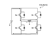
- the first drive unit 7A has four switching elements 8Aa, 8Ab, 8Ac, 8Ad.
- the collector of switching element 8Aa is connected to the positive electrode of power supply 9.
- the emitter of the switching element 8Aa is connected to the collector of the switching element 8Ab and to the first end of the winding 4A.
- the emitter of switching element 8Ab is connected to the negative electrode of power supply 9.
- the collector of switching element 8Ac is connected to the positive electrode of power supply 9.
- the emitter of the switching element 8Ac is connected to the collector of the switching element 8Ad and to the second end of the winding 4A.
- the emitter of the switching element 8Ad is connected to the negative electrode of the power supply 9.
- diodes are connected in parallel so that current flows from the emitter to the collector.
- the switching element 8Ab and the switching element 8Ac are always off, and only diodes in parallel are used.
- the second drive unit 7B has four switching elements 8Ba, 8Bb, 8Bc, 8Bd.
- the collector of switching element 8Ba is connected to the positive electrode of power supply 9.
- the emitter of the switching element 8Ba is connected to the collector of the switching element 8Bb and to the first end of the winding 4B.
- the emitter of switching element 8Bb is connected to the negative electrode of power supply 9.
- the collector of switching element 8Bc is connected to the positive electrode of power supply 9.
- the emitter of the switching element 8Bc is connected to the collector of the switching element 8Bd and to the second end of the winding 4B.
- the emitter of switching element 8Bd is connected to the negative electrode of power supply 9.
- diodes are connected in parallel so that current flows from the emitter to the collector.
- the switching element 8Bb and the switching element 8Bc are always off, and only diodes in parallel are used.
- the third drive unit 7C includes four switching elements 8Ca, 8Cb, 8Cc, and 8Cd.
- the collector of switching element 8Ca is connected to the positive electrode of power supply 9.
- the emitter of the switching element 8Ca is connected to the collector of the switching element 8Cb and to the first end of the winding 4C.
- the emitter of switching element 8Cb is connected to the negative electrode of power supply 9.
- the collector of switching element 8Cc is connected to the positive electrode of power supply 9.
- the emitter of the switching element 8Cc is connected to the collector of the switching element 8Cd and to the second end of the winding 4C.
- the emitter of switching element 8Cd is connected to the negative electrode of power supply 9.
- diodes are connected in parallel so that current flows from the emitter to the collector.
- the switching element 8Cb and the switching element 8Cc are always off, and only diodes in parallel are used.
- the first drive unit 7A, the second drive unit 7B, and the third drive unit 7C of the drive device 6 turn on and off the respective switching elements according to the command of the control device 5 shown in FIG.
- a voltage V is sequentially applied to 4A, 4B, 4C.
- the drive device 6 changes the magnetic field of the windings 4A, 4B, 4C, and attracts the teeth 3T of the rotor 3 at appropriate timing to rotate the rotary electric machine 1.
- FIG. 4 is a view showing the positional relationship between the stator 2 and the rotor 3 of the rotary electric machine 1.
- the rotor 3 is rotated in the direction indicated by the arrow R by an internal combustion engine or the like fastened to the rotary electric machine 1 via the shaft 1S.
- the rotary electric machine 1 when the rotary electric machine 1 generates torque in the same direction as the arrow R, power is generated, that is, powering is performed.
- the electric power is generated, that is, regenerated.
- the electrical angle ⁇ e is a rotation angle in which one cycle of the current waveform is 360 degrees, and is defined by the mechanical angle ⁇ m and the number of poles of the rotor 3.
- the electrical angle ⁇ e in a state where one tooth 3Ta of the rotor 3 and one tooth 2T of the stator 2 face each other is set to 0 degree.
- the rotor 3 rotates, and the electrical angle ⁇ e in a state in which the next teeth 3Tb adjacent to the teeth 3Ta of the rotor 3 face the teeth 2T of the stator 2 is set to 360 degrees.
- the rotary electric machine 1 Focusing on the teeth 3Tb of the rotor 3, when the teeth 3Tb are closer to the teeth 2T of the stator 2 than the teeth 3Ta, when the windings 4 of the teeth 2T are energized, the rotary electric machine 1 generates power, that is, power running. This is a range in which the electrical angle ⁇ e is 180 degrees ⁇ e ⁇ 360 degrees. When the electric angle ⁇ e is 0 degrees and 180 degrees, no torque is generated even if the winding 4 is energized.
- FIGS. 5-1, 5-2 and 6 are diagrams for explaining control examples of the control device 5 according to the present embodiment.
- the vertical axis represents the current Ic flowing through the winding 4 and the horizontal axis represents the electrical angle ⁇ e.
- FIG. 5A shows a state in which the rotary electric machine 1 is in regeneration
- FIG. 5B shows a state in which the rotary electric machine 1 is in power running.
- the vertical axis is the flux linkage ⁇
- the horizontal axis is the current Ic flowing through the winding 4.
- 5A, 5B and 6 show the current Ic and the flux linkage ⁇ of one phase of the rotary electric machine 1.
- the flux linkage ⁇ is represented by a value obtained by integrating the voltage applied to the winding 4 with time.
- the locus of the flux linkage ⁇ of the winding 4 and the current Ic flowing through the winding 4 changes in the direction indicated by the arrow G in FIG. 6 (clockwise in FIG. 6).
- the locus of the flux linkage ⁇ of the winding 4 and the current Ic flowing through the winding 4 changes in the direction indicated by the arrow P in FIG. 6 (counterclockwise in FIG. 6).
- the inductance which is the ratio between the flux linkage ⁇ and the current, fluctuates significantly as compared with other types of motors.
- the flux linkage ⁇ ⁇ ⁇ ⁇ ⁇ is directly controlled by determining the switching timing for controlling the magnetic field not from the current but from the voltage applied to the winding 4 and the application time.
- FIG. 7 to 9 are diagrams for explaining the operation of the drive device 6 that operates based on the command of the control device 5 according to the present embodiment.
- FIG. 10 is a view showing an example of a rotation angle at which a torque is easily generated and an example of a rotation angle at which a torque is hardly generated.
- the drive unit 7 when the first drive unit 7A, the second drive unit 7B and the third drive unit 7C are not distinguished, they are referred to as the drive unit 7 and the respective switching elements are denoted by reference numerals 8a, 8b, 8c and 8d. .
- the control device 5 controls the rotating electrical machine 1 based on the electrical angle ⁇ e.
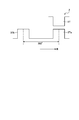
- driving the voltage V corresponding to each period with the first period ⁇ e1, the second period ⁇ e2, the third period ⁇ e3 and the fourth period ⁇ e4 being one cycle, ie, 360 electrical degrees ⁇ e It applies to winding 4A, 4B, 4C of each phase via the apparatus 6.
- the control device 5 shifts the phase of the voltage V applied to the windings 4A, 4B, 4C of each phase by a value obtained by dividing 360 degrees by the electrical angle ⁇ e by the number of phases. In the present embodiment, since the number of phases is 3, the phase is applied by being shifted by 120 degrees. Since the product of the phase shift and the number of phases is 360 degrees, it coincides with one cycle of the current Ic applied to each of the windings 4A, 4B, 4C.
- the first period ⁇ e1 is a period in which a first voltage is applied to each phase to increase the flux linkage ⁇ .
- the second period ⁇ e2 is a period during which the interlinking magnetic flux ⁇ is held by applying 0 volt to each phase after the first period ⁇ e1.
- the third period ⁇ e3 is a period after the second period ⁇ e2 in which a second voltage is applied to each phase in the direction opposite to the first voltage to reduce the flux linkage ⁇ .
- the fourth period ⁇ e4 is a period in which 0 volt is applied to each phase to hold the flux linkage ⁇ ⁇ from the third period ⁇ e3 to the first period ⁇ e1 of the next cycle.
- the fourth period ⁇ e4 may be zero. Further, since the interlinking magnetic flux ⁇ is maximized in the second period ⁇ e 2, it is desirable to set the second period ⁇ e 2 to a rotation angle at which a torque is easily generated as shown in FIG. This corresponds to setting the second period ⁇ e2 to a rotational angle that is likely to change in the lateral direction in FIG.
- the first voltage may be the voltage of the power supply 9 supplied to the drive device 6 or may be a voltage obtained by boosting or reducing the voltage of the power supply 9.
- the second voltage is opposite in polarity to the first voltage and has the same absolute value, and when applied to the windings 4A, 4B, 4C, the polarity is opposite to the first voltage.
- the fluctuation of the first voltage and the fluctuation of the second voltage in the same cycle are described as being the same value as being negligible, but the fluctuation of the first voltage and the fluctuation of the second voltage can not be ignored.
- the length of each period may be finely adjusted according to the magnitude of the voltage fluctuation.
- the control device 5 controls the second period ⁇ e2 to a value between the first value and the second value. That is, the second period ⁇ e2 is set to a value equal to or greater than the first value and equal to or less than the second value.
- the second value is a value which is larger than the first value and is obtained by dividing one cycle of the voltage V applied to the windings 4A, 4B, 4C by the number of phases of the rotary electric machine 1. In the present embodiment, since the rotary electric machine 1 has three phases, the second value is 120 degrees in electrical angle.
- the first value is about half of the second value, for example, about 60 degrees in electrical angle (60 degrees in the present embodiment), but is not limited thereto, and is changed according to the specifications and use environment of the rotating electrical machine 1 .
- One cycle of the voltage applied to the windings 4A, 4B, 4C of each phase of the rotary electric machine 1 is the first period ⁇ e1, the second period ⁇ e2, the third period ⁇ e3, the third period in either of the power running and the regeneration. It is expressed in the order of four periods ⁇ e4.
- the voltage of the power supply 9 is applied to the winding 4 by turning on the switching elements 8 a and 8 d of the driving unit 7 and turning off the switching elements 8 b and 8 c. .
- the switching element 8b and the switching element 8c are off in all periods, and only diodes in parallel are used.
- the voltage (+) of the positive electrode of the power source 9 is applied to the switching element 8 a side of the winding 4
- the voltage ( ⁇ ) of the negative electrode of the power source 9 is applied to the switching element 8 d side of the winding 4.
- the flux linkage ⁇ of the winding 4 is increased (excitation), as shown in FIGS. 5-1 and 5-2.
- the current Ic of the winding 4 is increased.
- the third period ⁇ e3 by switching off both of the switching elements 8a and 8d of the drive unit 7 from the state of the second period ⁇ e2, a diode parallel to the switching element 8b of the drive unit 7
- the voltage of the power source 9 is applied to the winding 4 by turning on a diode parallel to the switching element 8 c.
- the voltage (+) of the positive electrode of the power source 9 is applied to the switching element 8 c side of the winding 4
- the voltage ( ⁇ ) of the negative electrode of the power source 9 is applied to the switching element 8 b side of the winding 4. That is, the polarity of the voltage applied to the winding 4 is opposite to that of the first period ⁇ e1.
- the switching elements 8a, 8b, 8c, 8d and the diodes in parallel with each other are different depending on the value of the flux linkage ⁇ at the end of the third period ⁇ e3. 0 volts is applied to both ends of 4. Therefore, the value of the flux linkage ⁇ does not change, as in the second period ⁇ e 2.
- the flux linkage ⁇ is 0, ie, the current Ic becomes 0 at the end of the third period ⁇ e3, the diode is automatically turned off and switched to the fourth period ⁇ e4.
- the fourth period ⁇ e4 may be zero.
- the control device 5 after operating the switching element of the driving device 6 during the first period ⁇ e1, the control device 5 does not change the on / off state of the switching element of the driving device 6 until the end of the first period ⁇ e1. .
- the control device 5 After operating the switching element of the driving device 6 at the start of the second period ⁇ e2, the control device 5 does not change the on / off state of the switching element of the driving device 6 until the end of the second period ⁇ e2.
- the control device 5 After operating the switching element of the driving device 6 at the start of the third period ⁇ e3, the control device 5 starts the first period ⁇ e1 at the end of the third period ⁇ e3 or when the fourth period ⁇ e4 is 0. The on / off state of the switching element of the drive device 6 is not changed until the previous predetermined period.
- the control device 5 does not change the on / off state of the switching element of the driving device 6 until the end of the fourth period ⁇ e4.
- the flux linkage ⁇ in this period becomes constant.
- the flux linkage ⁇ of the second period ⁇ e 2 has a maximum value.
- the control device 5 and the control method of the rotating electrical machine according to the present embodiment perform control to apply a voltage to the winding 4 also during the second period ⁇ e 2, for example, compared to the case where the current Ic flowing through the winding 4 is a rectangular wave.
- the maximum value of the flux linkage ⁇ generated in the windings 4A, 4B and 4C of each phase can be reduced, and the amount of change in the flux linkage ⁇ can also be reduced.
- the control method of the control device 5 and the rotating electrical machine of the present embodiment controls to apply a voltage to the winding 4 also during the second period ⁇ e 2
- the maximum value of the magnetic flux is smaller and the amount of change is smaller as compared with the control in which the minimum value is not defined in the second period ⁇ e2.
- control for applying a voltage to the winding 4 also in the second period ⁇ e2 and control in which a minimum value is not defined in the second period ⁇ e2 Since the amount of change in magnetic flux is small in comparison, the core loss is small, and the decrease in efficiency of the rotary electric machine 1 can be suppressed.
- the excitation force of the noise of the rotary electric machine 1 is a pulsation of the radial direction component of the electromagnetic force in each tooth, and this is referred to as an excitation force Fr.
- the instantaneous value of the excitation force Fr at each tooth is known equation (1) in the opposite state. Further, when equation (1) is modified, equation (2) is obtained.
- Fr (B 2 ⁇ A) / (2 ⁇ ⁇ ) (1)
- Fr ⁇ 2 / (2 ⁇ ⁇ ⁇ N 2 ⁇ A) ⁇ ⁇ ⁇ (2)
- B is the magnetic flux density
- ⁇ is the permeability of vacuum
- N is the number of turns of the pole pair of the winding 4
- A is the cross-sectional area of the teeth 2T of the stator 2.
- the maximum value of the pulsation of the excitation force Fr at each tooth can be approximated as being proportional to the square of the maximum value of the flux linkage ⁇ in each phase except near the non-facing side. Since the excitation force Fr does not substantially occur near the non-facing side, the minimum value of the pulsation can be approximated to zero.
- the control device 5 and the control method of the rotating electrical machine of the present embodiment compare the control of applying a voltage to the winding 4 also in the second period ⁇ e 2 and the control in which the minimum value is not defined in the second period ⁇ ⁇ e Since the maximum value of the flux linkage ⁇ is small, the pulsation of the excitation force Fr is small, so noise and vibration in each tooth are suppressed.
- FIG. 11 is a diagram showing an example of the A-phase, B-phase, and C-phase excitation forces Fr in control in which the current Ic flowing through the winding 4 becomes a rectangular wave.
- FIG. 11 shows a comparative example.
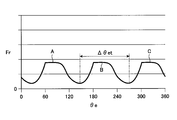
- FIG. 12 is a diagram showing an example of the A-phase, B-phase, and C-phase excitation force Fr in the control method of the rotating electrical machine of the present embodiment by the control device 5. ⁇ et is one cycle of the excitation force Fr.
- FIG. 11 shows the A-phase in control in which the current Ic flowing through the winding 4 becomes a rectangular wave when the number of poles of the rotary electric machine is larger than that of this embodiment and the excitation force Fr of each phase can be considered to be concentrated at the same location.
- FIG. 14 shows an example of the resultant force of the excitation force Fr in the B phase and the C phase.
- FIG. 12 shows an example of the resultant force of the excitation force Fr in the A phase, the B phase and the C phase in the control method of the rotating electrical machine of the present embodiment by the control device 5.
- the resultant force of the excitation force Fr in the A phase, the B phase and the C phase has a large pulsation.
- mechanical resonance tends to be a problem.
- the resultant force of the excitation force Fr in the A phase, the B phase and the C phase in the control method of the rotating electrical machine of the present embodiment by the control device 5 shown in FIG. Be done.
- the number of poles of the rotating electrical machine is small and the number of poles of the rotating electrical machine 1 is large when the excitation force Fr is close to independent in each phase. Noise and vibration are suppressed both when the force Fr is close to the combined force of each phase.
- the cross-sectional area of the core of the stator 2 and the core of the rotor 3 of the rotary electric machine 1 needs to have a size that allows at least the maximum magnetic flux to pass through.
- the control method of the control device 5 and the rotating electrical machine of the present embodiment is the maximum in comparison with the control of applying a voltage to the winding 4 also in the second period ⁇ e2 and the control in which the minimum value is not defined in the second period ⁇ e2. Since the magnetic flux is small, the core of the stator 2 and the core of the rotor 3 can be miniaturized.
- the average torque of the rotating electrical machine 1 is the area enclosed by the locus of the flux linkage ⁇ shown in FIG. 6 and the current Ic flowing through the winding 4 (the area enclosed by the solid line RT in the example shown in FIG. Proportional to Since the height of the ⁇ Ic area is proportional to the applied voltage and the first period ⁇ e1 as shown in FIG. 6, the average torque can be increased by increasing the applied voltage or the first period ⁇ e1.
- the control device 5 and the control method of the rotating electrical machine according to this embodiment flow the current Ic in the winding 4 so that the region surrounded by the solid line RT is filled from the region where the flux linkage ⁇ is small. That is, it is possible to significantly reduce the amount of change in the flux linkage ⁇ per average torque.
- the switching element 8a , 8d on and off only once each.
- the number of times the switching elements 8a and 8d are turned on in the first period ⁇ e1 of the next cycle is reduced. It can be considered that the on and off are left once each. Therefore, in the control device 5 and the control method of the rotating electrical machine of the present embodiment, since the switching loss of the drive device 6 can be brought close to the minimum value, the drive device 6 can be controlled with high efficiency. In addition, since the magnetic flux fluctuation and the decrease in the Ic area due to the switching can be eliminated, the iron loss of the rotary electric machine 1 can be further reduced.
- the flux linkage ⁇ in the second period ⁇ e2 increases, so the torque generated by the rotary electric machine 1 increases. For this reason, even when the second period ⁇ e2 is set, if the first period ⁇ e1 is made too long in order to increase the torque, the second period ⁇ e2 becomes short. That is, in one cycle of the voltage V applied to the winding 4, the period of the circulation becomes short, so that the constant period of the flux linkage ⁇ becomes short. As a result, the period in which the magnetic flux does not change decreases, and the iron loss of the rotary electric machine 1 increases. Further, since the maximum magnetic flux increases, the core of the stator 2 and the core of the rotor 3 become large.
- the period of free flow and the period in which the flux linkage ⁇ is constant are secured even at high torque, and iron loss of the rotating electrical machine 1 is maintained. Suppress the increase.
- FIG. 13 is a view showing an example of the current Ic flowing in each phase when the control device 5 according to the present embodiment controls the rotary electric machine 1.
- the sum ⁇ et of the first period ⁇ e1 and the second period ⁇ e2 is a second value, and in the present embodiment, one period of the voltage V applied to the winding 4 It is preferable to use a value divided by the number of phases of the rotating electrical machine 1.
- ⁇ et which is the sum of the first period ⁇ e1 and the second period ⁇ e2 is 120 degrees in electrical angle.
- one cycle of the voltage V applied to the winding 4 by the sum ⁇ et of the period of excitation and the period of reflux is Is a value obtained by dividing the number of phases of the rotating electrical machine 1.
- the phases of the A-phase, the B-phase and the C-phase are shifted by 120 degrees in electrical angle. Since the sum ⁇ et of the first period ⁇ e1 and the second period ⁇ e2 becomes a value obtained by dividing one cycle of the voltage V applied to the winding 4 by the number of phases of the rotary electric machine 1, the third period ⁇ e3 of the A phase
- the B-phase first period ⁇ e1 overlaps
- the B-phase third period ⁇ e3 overlaps the C-phase first period ⁇ e1
- the C-phase third period ⁇ e3 overlaps the A-phase first period ⁇ e1.
- the total of the magnetic fluxes of the entire rotary electric machine 1 becomes constant. Since iron loss is generated by a change in magnetic flux, by making the total of the magnetic fluxes of the entire rotating electric machine 1 constant, part of the change in magnetic flux of each phase cancels out in the rotor 3 and the stator 2, and as a result, the rotating electric machine The iron loss of 1 is reduced.
- the sum ⁇ et of the first period ⁇ e1 and the second period ⁇ e2 is defined as a value obtained by dividing one cycle of the voltage V applied to the winding 4 by the number of phases of the rotary electric machine 1, the first period ⁇ e1 is made longer Then, the second period ⁇ e2 becomes relatively short. Therefore, as described above, by providing a minimum value in the second period ⁇ e2, the period of circulation and the period in which the flux linkage ⁇ becomes constant are secured, and the iron loss of the rotary electric machine 1 increases and the noise increases. Can be suppressed.
- the sum ⁇ et of the first period ⁇ e1 and the second period ⁇ e2 is a value obtained by dividing one cycle of the voltage V applied to the winding 4 by the number of phases of the rotary electric machine 1, the excitation and the demagnetization are ideally Overlap completely. In fact, due to the resistance of the winding 4 or the like, a slight error may occur between the timing of excitation and the timing of demagnetization. Therefore, in the control device 5 and the control method of the rotating electrical machine of the present embodiment, the sum ⁇ et of the first period ⁇ e1 and the second period ⁇ e2 may be finely adjusted in consideration of the above-described error.
- the first period ⁇ e1 is lengthened to increase the torque of the rotary electric machine 1
- the sum ⁇ et of the first period ⁇ e1 and the second period ⁇ e2 exceeds the second value.
- the flux linkage ⁇ has already become a large value. Therefore, the influence of the flux linkage ⁇ due to the fact that the excitation and the demagnetization do not completely overlap becomes relatively small, and an effect of suppressing an increase in iron loss and an increase in noise of the rotary electric machine 1 can be obtained.
- FIGS. 14 and 15 are diagrams showing the relationship between the current Ic flowing through the winding 4 and the electrical angle ⁇ e during continuous energization in which the fourth period ⁇ e4 is zero.
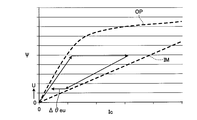
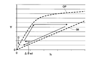
- FIGS. 16 and 17 are diagrams showing the relationship between the current Ic flowing through the winding 4 and the flux linkage ⁇ during continuous energization in which the fourth period ⁇ e4 is zero.
- the flux linkage ⁇ at the start of the first period ⁇ e1 of the next cycle is increased, and the torque of the rotary electric machine 1 can be increased.
- FIG. 15 and FIG. 17 the flux linkage ⁇ at the start of the first period ⁇ e1 of the next cycle is reduced, and the torque increased by the rotary electric machine 1 can be returned to the original state.
- the current Ic continues to flow continuously. This is referred to as continuous energization.
- the fourth period ⁇ e4 may be 0 as shown in FIGS. 14 and 15.
- the control device 5 performs switching from the third period ⁇ e3 to the fourth period ⁇ e4, for example, the previous time.
- the fourth period ⁇ e4 is 0, the flux linkage ⁇ at the start of the first period ⁇ e1 of the next cycle can be increased by changing the end of the third period ⁇ e3 to the fourth period ⁇ e4.
- the first period of the next period starts from the fourth period ⁇ e4.
- the fourth period ⁇ e4 By delaying the switching to the period ⁇ e1 more than that, for example, the previous control period, it is possible to reverse the increase in the flux linkage ⁇ in the next period.
- the fourth period ⁇ e4 is 0, the increase of the flux linkage ⁇ can be restored in the next period by changing the beginning of the first period ⁇ e1 of the next period to the fourth period ⁇ e4. For example, by changing the first period ⁇ e1 to the fourth period ⁇ e4 during the period ⁇ ed shown in FIG.
- the direction in which the flux linkage ⁇ decreases as shown in FIG. 17 (the direction indicated by the arrow D)
- the relationship between the flux linkage ⁇ of the winding 4 and the current Ic flowing through the winding 4 also moves in the decreasing direction as a whole (moving from the alternate long and short dashed line to the solid line in FIG. 15).
- the control device 5 delays the switching of the period between the fourth period ⁇ e4 and the first period ⁇ e1 of the next period, for example, more than that of the previous control period, or when the fourth period ⁇ e4 is 0.
- By changing the beginning of the first period ⁇ e1 of the next cycle to the fourth period ⁇ e4 it is possible to reduce the torque of the rotary electric machine 1 that has been increased.
- all the windings 4A, 4B, and 4C of each phase are continuously energized, but the present embodiment is not limited to the case where all the phases are similarly energized continuously.
- only the winding 4A may be continuously energized, or the increase amount of the flux linkage ⁇ may be different in each phase.
- the change in ⁇ Ic area that determines the torque of the rotating electrical machine 1 is the flux linkage ⁇ and the current Ic. Both can be small areas around zero.
- the control device 5 and the control method of the rotating electrical machine of the present embodiment the error of the torque of the rotating electrical machine 1 can be reduced even if continuous energization is performed.
- the winding is performed with the voltage applied to the winding 4 as zero before the start of excitation or at the end of demagnetization except that the winding 4 is generated.
- the command value of the voltage applied to the line 4 does not change. For this reason, in the control device 5 and the control method of the rotating electrical machine of the present embodiment, torque can be reliably adjusted with simple control logic in continuous energization. Furthermore, since the amount to adjust the flux linkage ⁇ is the product of the voltage applied to the winding 4 and the change amount of the period ⁇ eu, ⁇ ed, ie, the period of refluxing, there is an advantage that calculation in control becomes easy. .
- control device 5 and the control method of the rotating electrical machine of the present embodiment can reduce the change in magnetic flux of the rotating electrical machine 1 even during continuous energization and can reduce the number of switchings of the drive device 6, the rotating electrical machine 1 and The reduction in efficiency of the drive device 6 can be suppressed, and the noise and vibration of the rotary electric machine 1 can be suppressed.
- the flux linkage ⁇ may be adjusted at one time, or may be adjusted in multiple times.
- the actual current Ic flowing through the winding 4 and the command value of the current Ic may be slightly different. Therefore, in the control device 5 and the control method of the rotating electrical machine according to the present embodiment, the command value of the current Ic is feedback-controlled so that the difference between the measured current Ic and the command value of the current Ic becomes zero. The difference between the actual current Ic flowing through the winding 4 and the command value of the current Ic may be zero.
- FIG. 18 is a diagram showing the relationship between the current Ic flowing through the winding 4 in one phase of the rotary electric machine 1 and the electrical angle ⁇ e.
- FIG. 19 is a diagram showing the relationship between the current Ic flowing through the A-phase, B-phase and C-phase windings 4 of the rotary electric machine 1 and the electrical angle ⁇ e.
- FIG. 20 is a diagram showing an example of the results when torque is changed while keeping the rotational speed of the rotating electrical machine 1 constant, by the relationship between the flux linkage ⁇ at the midpoint of the reflux and the current Ic flowing through the winding 4 is there.
- the control device 5 and the control method of the rotary electric machine of the present embodiment change a unit torque of the middle point ⁇ e2c of the second period ⁇ e2.
- the middle point ⁇ e2c of the second period ⁇ e2 is an intermediate angle between the angle ⁇ es at the start of the second period ⁇ e2 and the angle ⁇ ef at the end of the second period ⁇ e2, as shown in FIG.
- the middle point ⁇ e2c can be obtained by ( ⁇ es + ⁇ ef) / 2. Since the angles ⁇ es and ⁇ ef are command values for determining the second period ⁇ e2, the control device 5 can easily obtain the middle point ⁇ e2c of the second period ⁇ e2.
- the control device 5 sets the change amount per unit torque of the middle point ⁇ e2c of the second period ⁇ e2 to, for example, 1 degree / Nm, or changes the change amount per unit rotational speed to, for example 0.1 degree / It can be called rpm (revolution per minute).
- the amount of change per unit torque and the amount of change per unit rotational speed are not limited to this example.
- the control device 5 sets the change amount per unit torque of the middle point ⁇ e2c of the second period ⁇ e2 to be equal to or less than the aforementioned change amount.
- a limitation is placed on the amount of change per unit torque of the middle point ⁇ e2c of ⁇ e2.
- control device 5 rotates by causing the period of excitation of the winding 4 and the period of demagnetization to overlap by a fixed amount even if the length of the second period ⁇ e2 changes by using the middle point ⁇ e2 c as a reference. Since the efficiency decrease and the noise of the electric machine 1 are suppressed, as a result, the rotating electric machine 1 has high efficiency and low noise.
- control device 5 changes the amount of change per unit torque and the amount of change per unit rotational speed of the middle points ⁇ e2c_A, ⁇ e2c_B, ⁇ e2c_C of the second periods ⁇ e2_A, ⁇ e2_B, ⁇ e2_C of A phase, B phase and C phase. Place restrictions on Then, when at least one of the rotational speed and the torque of the rotary electric machine 1 changes, a sudden change in the difference between the period ⁇ eA and the period ⁇ eB is suppressed.
- the period ⁇ eA is a period between the midpoint ⁇ e2c_A of the second period ⁇ e2_A of A phase and the midpoint ⁇ e2c_B of the second period ⁇ e2_B of B phase
- ⁇ eB is the midpoint ⁇ e2c_B of the second period ⁇ e2_B of B phase It is a period between the middle point ⁇ e2c_C of the second period ⁇ e2_C of the C phase.
- T1, T2, T3 and T4 indicating the middle point ⁇ e2c of the second period ⁇ e2 are plotted on the curve CV of monotonically increasing Be done.
- the control device 5 may not change the middle point ⁇ e2c of the second period ⁇ e2 or may change it.
- the control device 5 may change only the second period ⁇ e2 by fixing the middle point ⁇ e2c of the second period ⁇ e2 or providing a change amount per unit torque and a change amount per unit rotational speed.
- the control method of the rotary electric machine and the control device of the rotary electric machine for realizing the control method according to the present embodiment have been described, the case where the maximum current rating of the switching element is sufficiently large has been described in the present embodiment.
- the application targets such as the control method of the rotating electrical machine according to this embodiment are not limited to the case where the maximum current rating of the switching element is sufficiently large.
- the maximum current in this embodiment is generated at the right end of the linear portion where the flux linkage ⁇ of the second period ⁇ e2 is constant.
- the maximum current rating of the switching element is insufficient, for example, by adding switching at the right end of the linear portion where the flux linkage ⁇ of the second period ⁇ e2 becomes constant, the maximum current can be within the rating of the switching element. You may hold it. In this case, only the minute region at the right end of the straight portion in FIG. 6 changes, so the rotary electric machine 1 can maintain high efficiency and low noise control as described above.
- FIG. 21 is a view showing an example of a working machine provided with a control device of a rotating electrical machine for realizing the control method of the rotating electrical machine according to the present embodiment.
- the hybrid hydraulic shovel 10 will be described as an example of a working machine, but the control method of the rotating electrical machine according to the present embodiment and the application target of the control device 5 for realizing the same are limited to the hybrid hydraulic shovel 10 Instead, it may be a hybrid wheel loader or an electric dump truck or the like.
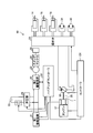
- the hybrid hydraulic shovel 10 has an engine 17 as a drive source, a hydraulic pump 18 and a rotating electric machine 1.
- the rotary electric machine 1 functions as a generator and a motor.
- the rotary electric machine 1 is an SRM.
- a diesel engine is used as the engine 17, and a variable displacement hydraulic pump is used as the hydraulic pump 18.
- the hydraulic pump 18 and the rotary electric machine 1 are mechanically connected to the drive shaft 20 of the engine 17, and when the engine 17 rotates, the hydraulic pump 18 and the rotary electric machine 1 rotate.
- the hydraulic drive system of the hybrid hydraulic shovel 10 has an operation valve 33, a boom hydraulic cylinder 14, an arm hydraulic cylinder 15, a bucket hydraulic cylinder 16, a right traveling hydraulic motor 34, a left traveling hydraulic motor 35, etc. There is.
- the hydraulic pump 18 serves as a hydraulic oil supply source to the hydraulic drive system to drive these hydraulic devices.
- the electric drive system includes a first drive device 21, a second drive device 22, a booster 26, a power storage device 25, a swing motor 23, and the like.
- the first drive device 21 is connected to the rotary electric machine 1 via a power cable.
- the second drive device 22 is connected to the first drive device 21 via a large current wiring such as a bus bar.
- the booster 26 is provided between the first drive device 21 and the second drive device 22 via a large current wiring such as a bus bar.
- Power storage device 25 is connected to booster 26.
- the swing motor 23 is connected to the second drive 22 via a power cable.
- the first drive device 21 and the second drive device 22 are installed, for example, as components inside the inverter.
- the swing motor 23 is mechanically connected to the swing machinery 24. At least one of the electric power generated by the rotary electric machine 1 and the electric power stored in the storage device 25 serves as the electric power for driving the swing motor 23.
- the swing motor 23 is driven by the power supplied from at least one of the rotary electric machine 1 and the power storage device 25 to cause the upper swing body 28 to swing by performing a powering operation. Further, the swing motor 23 performs a regeneration operation when the upper swing body 28 rotates and decelerates, supplies power (regeneration energy) generated by the regeneration operation to the power storage device 25 (charge), or uses the rotating electric machine 1 as a motor. Supply as power for use.
- the rotary electric machine 1 supplies (charges) the electric power generated by being driven by the engine 17 to the power storage device 25 and supplies the electric power to the swing motor 23 according to the situation.
- the rotating electrical machine 1 functions as a motor when the output of the engine 17 is insufficient, and assists the output of the engine 17.
- the rotating electrical machine 1 is an SRM.
- the rotating electric machine 1 has a shaft mechanically coupled to a drive shaft 20 of the engine 17. With such a structure, the rotary electric machine 1 rotates the rotor 3 of the rotary electric machine 1 by the drive of the engine 17 to generate power or assist.
- Booster 26 is provided between rotating electric machine 1 and swing motor 23 and power storage device 25.
- the booster 26 boosts / lowers the voltage of the electric power (electrical energy stored in the storage device 25) supplied to the rotary electric machine 1 or the swing motor 23 via the first drive device 21 or the second drive device 22.
- the voltage raised and lowered is applied to the swing motor 23 when the swing motor 23 performs a powering operation (swing acceleration), and is applied to the rotary electric machine 1 when the output of the engine 17 is assisted.
- the rotational speed or torque of the rotary electric machine 1 and the swing motor 23 are controlled by the first drive device 21 and the second drive device 22, respectively, under the control of the hybrid controller C2.
- the hybrid controller C2 controls the rotating electrical machine 1 by executing the control method of the rotating electrical machine according to the present embodiment.
- the hybrid controller C2 functions as a control device of the rotating electrical machine according to the present embodiment.
- the hybrid controller C2 may control not only the rotary electric machine 1 but also any device.
- the hybrid controller C2 monitors the charge amount of the storage device 25 (voltage of the storage device 25 and the like), and supplies (charges) the power generated by the rotating electrical machine 1 to the storage device 25 or supplies it to the swing motor 23 (power running Perform energy management, such as whether to supply power for operation.
- power storage device 25 stores the power generated by rotating electric machine 1.
- Power storage device 25 stores the electric power generated by regenerative operation of swing motor 23 when upper swing body 28 swings and decelerates.
- swing motor 23 for example, although a permanent magnet type synchronous rotating electric machine is used, it is not limited to this.
- SRM may be used for the swing motor 23 as well.
- the controller C1 is a combination of an arithmetic device such as a CPU (Central Processing Unit) and a memory (storage device), and is, for example, a microcomputer.
- the controller C1 controls the engine 17 and the hydraulic pump 18.
- the engine 17 can obtain a target engine output by properly controlling the fuel injection amount by the controller C1. That is, the controller C1 sets the rotational speed of the engine 17 and the torque that can be output according to the load state of the hybrid hydraulic shovel 10, and drives the engine 17.
- the hybrid controller C2 is a combination of an arithmetic device such as a CPU and a memory (storage device), and is, for example, a microcomputer.
- the hybrid controller C 2 controls the first drive device 21, the second drive device 22 and the booster 26 as described above under cooperative control with the controller C 1 to control the rotary electric machine 1, the swing motor 23 and the storage device 25. Control the transfer of power.
- the hybrid controller C2 stores, in the storage device, a computer program for causing the microcomputer to execute the processing procedure of the control method of the rotating electrical machine according to the present embodiment.
- the hybrid controller C2 When executing the control method of the rotating electrical machine according to the present embodiment, the hybrid controller C2 reads the computer program described above from the storage device, and executes the instructions described therein to thereby implement the rotating electrical machine according to the present embodiment.
- the rotary electric machine 1 is controlled by the control method of
- the hybrid hydraulic shovel 10 has the hybrid controller C2 that functions as a control device for the rotating electrical machine according to the present embodiment, the efficiency reduction and noise of the rotating electrical machine 1 can be suppressed. As a result, the rotating electrical machine can be highly efficient and low in noise. It can control.
- the rotary electric machine 1, the engine 17 and the hydraulic pump 18 are mounted in the vehicle body of the hybrid hydraulic shovel 10. However, since the space in the vehicle body is limited, it is preferable that the size of the rotary electric machine 1 be as small as possible.
- the core of the stator 2 and the core of the rotor 3 can be miniaturized, so the rotary electric machine 1 can also be miniaturized.
- the control device for the rotating electrical machine according to the present embodiment and the rotating electrical machine 1 controlled by the control device are suitable for the hybrid hydraulic shovel 10.
- control method of the rotating electrical machine according to the present embodiment and the example of applying the control device of the rotating electrical machine for realizing the same to a working machine have been described, application targets such as the control method of the rotating electrical machine according to the present embodiment are limited thereto I will not.
- the control method and the like of the rotary electric machine according to the present embodiment may be applied to, for example, a traveling rotary electric machine for driving an electric vehicle such as an electric automobile or a rotary electric machine for driving a compressor or a pump.
- this embodiment is not limited by the content mentioned above.
- the components of this embodiment include those which can be easily conceived by those skilled in the art, substantially the same components, and so-called equivalent ranges.
- the components of the present embodiment can be combined as appropriate.
- various omissions, replacements, or modifications of the components of the present embodiment can be made without departing from the scope of the present embodiment.
Landscapes
- Engineering & Computer Science (AREA)
- Power Engineering (AREA)
- Control Of Electric Motors In General (AREA)
- Control Of Ac Motors In General (AREA)
Abstract
Description
図1は、本実施形態に係る2相以上の回転電機1と、これを制御する回転電機の制御装置5とを示す図である。回転電機とは、電動機の動作と発電機の動作とを行う電磁機械である。回転電機1の制御装置(以下、適宜制御装置という)5は、回転電機1のシャフト1Sの回転速度及びトルクの少なくとも一方を制御するための制御信号を生成する。制御装置5は、例えば、生成した制御信号を駆動装置6に与えることにより、駆動装置6を介して回転電機1のシャフト1Sの回転を制御する。制御装置5は、例えば、マイクロコンピュータが用いられるが、これに限定されるものではない。制御装置5は、本実施形態に係る回転電機の制御方法を実行する。駆動装置6としては、例えば、複数のスイッチング素子を有する装置が用いられる。
Fr=(B2×A)/(2×μ)・・・(1)
Fr=ψ2/(2×μ×N2×A)・・(2)
図21は、本実施形態に係る回転電機の制御方法を実現する回転電機の制御装置を備えた作業機械の一例を示す図である。次においては、作業機械として、ハイブリッド油圧ショベル10を例として説明するが、本実施形態に係る回転電機の制御方法及びこれを実現する制御装置5の適用対象は、ハイブリッド油圧ショベル10に限定されるものではなく、ハイブリッドホイールローダー又は電気式ダンプトラック等であってもよい。
2 固定子
2T ティース
3 回転子
3T,3Ta,3Tb ティース
4,4A,4B,4C 巻線
5 制御装置
6 駆動装置
7 駆動部
7A 第1駆動部
7B 第2駆動部
7C 第3駆動部
9 電源
10 ハイブリッド油圧ショベル
11 回転角度センサ
12A,12B,12C 電流センサ
13 電圧センサ
C2 ハイブリッドコントローラ
Δθe1 第1期間
Δθe2,Δθe2_A,Δθe2_B,Δθe2_C 第2期間
Δθe2c,Δθe2c_A,Δθe2c_B,Δθe2c_C 第2期間の中点
Δθe3 第3期間
Δθe4 第4期間
Claims (13)
- 2相以上の回転電機を制御するにあたり、
前記回転電機が有する各相の巻線に、第1の電圧を印加して鎖交磁束を増加させる第1期間、前記第1期間の後に前記巻線に印加する電圧を0として前記鎖交磁束を保持する第2期間、前記第2期間の後に前記巻線に前記第1の電圧とは反対方向に第2の電圧を印加して前記鎖交磁束を減少させる第3期間、及び前記第3期間から次周期の前記第1期間まで前記巻線に印加する電圧を0として前記鎖交磁束を保持する第4期間を1周期とする電圧を印加するとともに、
前記第2期間を、第1の値から、前記第1の値よりも大きく、かつ前記1周期を前記回転電機の相数で除した第2の値の間の値に制御する、
回転電機の制御装置。 - 前記第1期間と前記第2期間との和が前記第2の値となる、請求項1に記載の回転電機の制御装置。
- 前記第1期間と前記第2期間との和が前記第2の値を超過する場合には、前記第2期間を前記第1の値に固定する、請求項1に記載の回転電機の制御装置。
- 前記第1期間の開始時における鎖交磁束が0よりも大きく、前記巻線に連続して電流が流れる状態の制御において、前記第1期間の開始時における鎖交磁束を増加させる場合に、前記第3期間から前記第4期間への切り替えを早める、又は前記第4期間が0の場合には、前記第3期間の最後を前記第4期間に変更する、請求項1に記載の回転電機の制御装置。
- 前記第1期間の開始時における鎖交磁束が0よりも大きく、前記巻線に連続して電流が流れる状態の制御において、前記第1期間の開始時における鎖交磁束を減少させる場合に、前記第4期間から次周期の前記第1期間への切り替えを遅延させる、又は前記第4期間が0の場合には、次周期の前記第1期間の最初を前記第4期間に変更する、請求項4に記載の回転電機の制御装置。
- 前記回転電機の回転速度及びトルクの少なくとも一方を変更する場合、前記第2期間の中点の単位トルクあたりの変化量及び単位回転速度あたりの変化量に制限を設ける、請求項1から請求項5のいずれか1項に記載の回転電機の制御装置。
- 前記2相以上の回転電機である2相以上のスイッチトリラクタンスモータと、
請求項1から請求項6のいずれか1項に記載の回転電機の制御装置と、
を含む、作業機械。 - 2相以上の回転電機を制御するにあたり、
前記回転電機が有する各相の巻線に、第1の電圧を印加して鎖交磁束を増加させる第1期間、前記第1期間の後に前記巻線に印加する電圧を0として前記鎖交磁束を保持する第2期間、前記第2期間の後に前記巻線に前記第1の電圧とは反対方向に第2の電圧を印加して前記鎖交磁束を減少させる第3期間、及び前記第3期間から次周期の前記第1期間まで前記巻線に印加する電圧を0として前記鎖交磁束を保持する第4期間を1周期とする電圧を印加し、
前記第2期間を、第1の値から、前記第1の値よりも大きく、かつ前記1周期を前記回転電機の相数で除した第2の値の間の値に制御する、
回転電機の制御方法。 - 前記第1期間と前記第2期間との和が前記第2の値となる、請求項8に記載の回転電機の制御方法。
- 前記第1期間と前記第2期間との和が前記第2の値を超過する場合には、前記第2期間を前記第1の値に固定する、請求項8に記載の回転電機の制御方法。
- 前記第1期間の開始時における鎖交磁束が0よりも大きく、前記巻線に連続して電流が流れる状態の制御において、前記第1期間の開始時における鎖交磁束を増加させる場合に、前記第3期間から前記第4期間への切り替えを早める、又は前記第4期間が0の場合には、前記第3期間の最後を前記第4期間に変更する、請求項8に記載の回転電機の制御方法。
- 前記第1期間の開始時における鎖交磁束が0よりも大きく、前記巻線に連続して電流が流れる状態の制御において、前記第1期間の開始時における鎖交磁束を減少させる場合に、前記第4期間から次周期の前記第1期間への切り替えを遅延させる、又は前記第4期間が0の場合には、次周期の前記第1期間の最初を前記第4期間に変更する、請求項11に記載の回転電機の制御方法。
- 前記回転電機の回転速度及びトルクの少なくとも一方を変更する場合、前記第2期間の中点の単位トルクあたりの変化量及び単位回転速度あたりの変化量に制限を設ける、請求項8から請求項12のいずれか1項に記載の回転電機の制御方法。
Priority Applications (2)
| Application Number | Priority Date | Filing Date | Title |
|---|---|---|---|
| JP2017558293A JP6883524B2 (ja) | 2015-12-25 | 2016-12-22 | 回転電機の制御装置、作業機械及び回転電機の制御方法 |
| DE112016003132.7T DE112016003132T5 (de) | 2015-12-25 | 2016-12-22 | Steuervorrichtung für eine rotierende elektrische Maschine, Arbeitsmaschine und Verfahren zur Steuerung einer rotierenden elektrischen Maschine |
Applications Claiming Priority (2)
| Application Number | Priority Date | Filing Date | Title |
|---|---|---|---|
| JP2015255378 | 2015-12-25 | ||
| JP2015-255378 | 2015-12-25 |
Publications (1)
| Publication Number | Publication Date |
|---|---|
| WO2017111101A1 true WO2017111101A1 (ja) | 2017-06-29 |
Family
ID=59090487
Family Applications (1)
| Application Number | Title | Priority Date | Filing Date |
|---|---|---|---|
| PCT/JP2016/088519 Ceased WO2017111101A1 (ja) | 2015-12-25 | 2016-12-22 | 回転電機の制御装置、作業機械及び回転電機の制御方法 |
Country Status (3)
| Country | Link |
|---|---|
| JP (1) | JP6883524B2 (ja) |
| DE (1) | DE112016003132T5 (ja) |
| WO (1) | WO2017111101A1 (ja) |
Citations (6)
| Publication number | Priority date | Publication date | Assignee | Title |
|---|---|---|---|---|
| JP2003111464A (ja) * | 2001-07-16 | 2003-04-11 | Hilti Ag | 電子式整流子電気モータの制動制御方法および回路 |
| US20080272721A1 (en) * | 2007-05-04 | 2008-11-06 | Switched Reluctance Drives Limited | Control of a brushless electrical machine |
| JP4456068B2 (ja) * | 2002-10-11 | 2010-04-28 | 株式会社ミツバ | 発電機の制御方法及び風力発電機 |
| JP2014195390A (ja) * | 2013-02-28 | 2014-10-09 | Denso Corp | スイッチトリラクタンスモータの制御装置 |
| JP2014220985A (ja) * | 2013-04-11 | 2014-11-20 | 株式会社デンソー | スイッチトリラクタンスモータの制御装置 |
| US20150002063A1 (en) * | 2010-06-25 | 2015-01-01 | The Board Of Regents, The University Of Texas System | Double saliency exterior rotor switched reluctance machine |
-
2016
- 2016-12-22 DE DE112016003132.7T patent/DE112016003132T5/de active Pending
- 2016-12-22 WO PCT/JP2016/088519 patent/WO2017111101A1/ja not_active Ceased
- 2016-12-22 JP JP2017558293A patent/JP6883524B2/ja active Active
Patent Citations (6)
| Publication number | Priority date | Publication date | Assignee | Title |
|---|---|---|---|---|
| JP2003111464A (ja) * | 2001-07-16 | 2003-04-11 | Hilti Ag | 電子式整流子電気モータの制動制御方法および回路 |
| JP4456068B2 (ja) * | 2002-10-11 | 2010-04-28 | 株式会社ミツバ | 発電機の制御方法及び風力発電機 |
| US20080272721A1 (en) * | 2007-05-04 | 2008-11-06 | Switched Reluctance Drives Limited | Control of a brushless electrical machine |
| US20150002063A1 (en) * | 2010-06-25 | 2015-01-01 | The Board Of Regents, The University Of Texas System | Double saliency exterior rotor switched reluctance machine |
| JP2014195390A (ja) * | 2013-02-28 | 2014-10-09 | Denso Corp | スイッチトリラクタンスモータの制御装置 |
| JP2014220985A (ja) * | 2013-04-11 | 2014-11-20 | 株式会社デンソー | スイッチトリラクタンスモータの制御装置 |
Also Published As
| Publication number | Publication date |
|---|---|
| JPWO2017111101A1 (ja) | 2018-10-18 |
| DE112016003132T5 (de) | 2018-03-29 |
| JP6883524B2 (ja) | 2021-06-09 |
Similar Documents
| Publication | Publication Date | Title |
|---|---|---|
| JP4452735B2 (ja) | 昇圧コンバータの制御装置および制御方法 | |
| JP5188723B2 (ja) | スイッチトリラクタンスモータの制御装置 | |
| JP6260624B2 (ja) | 制御装置 | |
| KR101940411B1 (ko) | 회로 및 회로를 위한 제어 방법 | |
| JP2021090238A (ja) | 制御装置 | |
| CN108111089B (zh) | 开关磁阻马达用的控制装置 | |
| JP2012196095A (ja) | 回転電機システム | |
| CN116472666B (zh) | 旋转电机的控制装置及电动助力转向装置 | |
| JP4493639B2 (ja) | 回転電機の制御装置 | |
| US11323056B2 (en) | Controller for AC rotary electric machine | |
| JP6883524B2 (ja) | 回転電機の制御装置、作業機械及び回転電機の制御方法 | |
| JP2009296835A (ja) | モータ制御装置 | |
| Nguyen et al. | Intermittent control for efficiency gain of a switched reluctance machine | |
| JP2023183491A (ja) | 交流回転機の制御装置、及び車両用発電電動機装置 | |
| KR102199891B1 (ko) | 스위치드 릴럭턴스 모터의 제어 장치 | |
| US10483897B2 (en) | Switched reluctance motor system, and method of controlling switched reluctance motor system | |
| JP6839896B2 (ja) | モータ制御装置および電動車両 | |
| JP7796874B2 (ja) | 回転電機制御装置 | |
| JP2019146383A (ja) | モータ制御装置 | |
| WO2025099920A1 (ja) | 回転電機の制御装置 | |
| JP2023183492A (ja) | 交流回転機の制御装置、及び車両用発電電動機装置 | |
| JPH06245314A (ja) | 電気自動車用永久磁石モータの制御装置 | |
| JP2008245495A (ja) | スイッチドリラクタンスモータの制御装置 | |
| JP2014166074A (ja) | 磁石レス巻線界磁モータの駆動回路 | |
| JP2009296834A (ja) | モータ制御装置 |
Legal Events
| Date | Code | Title | Description |
|---|---|---|---|
| 121 | Ep: the epo has been informed by wipo that ep was designated in this application |
Ref document number: 16878987 Country of ref document: EP Kind code of ref document: A1 |
|
| ENP | Entry into the national phase |
Ref document number: 2017558293 Country of ref document: JP Kind code of ref document: A |
|
| WWE | Wipo information: entry into national phase |
Ref document number: 112016003132 Country of ref document: DE |
|
| 122 | Ep: pct application non-entry in european phase |
Ref document number: 16878987 Country of ref document: EP Kind code of ref document: A1 |