WO2017110548A1 - 蓄電装置 - Google Patents
蓄電装置 Download PDFInfo
- Publication number
- WO2017110548A1 WO2017110548A1 PCT/JP2016/086875 JP2016086875W WO2017110548A1 WO 2017110548 A1 WO2017110548 A1 WO 2017110548A1 JP 2016086875 W JP2016086875 W JP 2016086875W WO 2017110548 A1 WO2017110548 A1 WO 2017110548A1
- Authority
- WO
- WIPO (PCT)
- Prior art keywords
- terminal
- insulating
- electrode
- electrode assembly
- negative electrode
- Prior art date
- Legal status (The legal status is an assumption and is not a legal conclusion. Google has not performed a legal analysis and makes no representation as to the accuracy of the status listed.)
- Ceased
Links
Images




Classifications
-
- H—ELECTRICITY
- H01—ELECTRIC ELEMENTS
- H01M—PROCESSES OR MEANS, e.g. BATTERIES, FOR THE DIRECT CONVERSION OF CHEMICAL ENERGY INTO ELECTRICAL ENERGY
- H01M50/00—Constructional details or processes of manufacture of the non-active parts of electrochemical cells other than fuel cells, e.g. hybrid cells
- H01M50/50—Current conducting connections for cells or batteries
- H01M50/572—Means for preventing undesired use or discharge
- H01M50/574—Devices or arrangements for the interruption of current
- H01M50/578—Devices or arrangements for the interruption of current in response to pressure
-
- H—ELECTRICITY
- H01—ELECTRIC ELEMENTS
- H01G—CAPACITORS; CAPACITORS, RECTIFIERS, DETECTORS, SWITCHING DEVICES, LIGHT-SENSITIVE OR TEMPERATURE-SENSITIVE DEVICES OF THE ELECTROLYTIC TYPE
- H01G11/00—Hybrid capacitors, i.e. capacitors having different positive and negative electrodes; Electric double-layer [EDL] capacitors; Processes for the manufacture thereof or of parts thereof
- H01G11/14—Arrangements or processes for adjusting or protecting hybrid or EDL capacitors
- H01G11/16—Arrangements or processes for adjusting or protecting hybrid or EDL capacitors against electric overloads, e.g. including fuses
-
- H—ELECTRICITY
- H01—ELECTRIC ELEMENTS
- H01G—CAPACITORS; CAPACITORS, RECTIFIERS, DETECTORS, SWITCHING DEVICES, LIGHT-SENSITIVE OR TEMPERATURE-SENSITIVE DEVICES OF THE ELECTROLYTIC TYPE
- H01G11/00—Hybrid capacitors, i.e. capacitors having different positive and negative electrodes; Electric double-layer [EDL] capacitors; Processes for the manufacture thereof or of parts thereof
- H01G11/74—Terminals, e.g. extensions of current collectors
-
- H—ELECTRICITY
- H01—ELECTRIC ELEMENTS
- H01G—CAPACITORS; CAPACITORS, RECTIFIERS, DETECTORS, SWITCHING DEVICES, LIGHT-SENSITIVE OR TEMPERATURE-SENSITIVE DEVICES OF THE ELECTROLYTIC TYPE
- H01G11/00—Hybrid capacitors, i.e. capacitors having different positive and negative electrodes; Electric double-layer [EDL] capacitors; Processes for the manufacture thereof or of parts thereof
- H01G11/74—Terminals, e.g. extensions of current collectors
- H01G11/76—Terminals, e.g. extensions of current collectors specially adapted for integration in multiple or stacked hybrid or EDL capacitors
-
- H—ELECTRICITY
- H01—ELECTRIC ELEMENTS
- H01G—CAPACITORS; CAPACITORS, RECTIFIERS, DETECTORS, SWITCHING DEVICES, LIGHT-SENSITIVE OR TEMPERATURE-SENSITIVE DEVICES OF THE ELECTROLYTIC TYPE
- H01G11/00—Hybrid capacitors, i.e. capacitors having different positive and negative electrodes; Electric double-layer [EDL] capacitors; Processes for the manufacture thereof or of parts thereof
- H01G11/78—Cases; Housings; Encapsulations; Mountings
-
- H—ELECTRICITY
- H01—ELECTRIC ELEMENTS
- H01G—CAPACITORS; CAPACITORS, RECTIFIERS, DETECTORS, SWITCHING DEVICES, LIGHT-SENSITIVE OR TEMPERATURE-SENSITIVE DEVICES OF THE ELECTROLYTIC TYPE
- H01G11/00—Hybrid capacitors, i.e. capacitors having different positive and negative electrodes; Electric double-layer [EDL] capacitors; Processes for the manufacture thereof or of parts thereof
- H01G11/78—Cases; Housings; Encapsulations; Mountings
- H01G11/82—Fixing or assembling a capacitive element in a housing, e.g. mounting electrodes, current collectors or terminals in containers or encapsulations
-
- H—ELECTRICITY
- H01—ELECTRIC ELEMENTS
- H01G—CAPACITORS; CAPACITORS, RECTIFIERS, DETECTORS, SWITCHING DEVICES, LIGHT-SENSITIVE OR TEMPERATURE-SENSITIVE DEVICES OF THE ELECTROLYTIC TYPE
- H01G2/00—Details of capacitors not covered by a single one of groups H01G4/00-H01G11/00
- H01G2/14—Protection against electric or thermal overload
-
- H—ELECTRICITY
- H01—ELECTRIC ELEMENTS
- H01G—CAPACITORS; CAPACITORS, RECTIFIERS, DETECTORS, SWITCHING DEVICES, LIGHT-SENSITIVE OR TEMPERATURE-SENSITIVE DEVICES OF THE ELECTROLYTIC TYPE
- H01G9/00—Electrolytic capacitors, rectifiers, detectors, switching devices, light-sensitive or temperature-sensitive devices; Processes of their manufacture
- H01G9/0003—Protection against electric or thermal overload; cooling arrangements; means for avoiding the formation of cathode films
-
- H—ELECTRICITY
- H01—ELECTRIC ELEMENTS
- H01G—CAPACITORS; CAPACITORS, RECTIFIERS, DETECTORS, SWITCHING DEVICES, LIGHT-SENSITIVE OR TEMPERATURE-SENSITIVE DEVICES OF THE ELECTROLYTIC TYPE
- H01G9/00—Electrolytic capacitors, rectifiers, detectors, switching devices, light-sensitive or temperature-sensitive devices; Processes of their manufacture
- H01G9/004—Details
- H01G9/008—Terminals
-
- H—ELECTRICITY
- H01—ELECTRIC ELEMENTS
- H01G—CAPACITORS; CAPACITORS, RECTIFIERS, DETECTORS, SWITCHING DEVICES, LIGHT-SENSITIVE OR TEMPERATURE-SENSITIVE DEVICES OF THE ELECTROLYTIC TYPE
- H01G9/00—Electrolytic capacitors, rectifiers, detectors, switching devices, light-sensitive or temperature-sensitive devices; Processes of their manufacture
- H01G9/004—Details
- H01G9/04—Electrodes or formation of dielectric layers thereon
- H01G9/048—Electrodes or formation of dielectric layers thereon characterised by their structure
-
- H—ELECTRICITY
- H01—ELECTRIC ELEMENTS
- H01M—PROCESSES OR MEANS, e.g. BATTERIES, FOR THE DIRECT CONVERSION OF CHEMICAL ENERGY INTO ELECTRICAL ENERGY
- H01M10/00—Secondary cells; Manufacture thereof
- H01M10/05—Accumulators with non-aqueous electrolyte
- H01M10/052—Li-accumulators
- H01M10/0525—Rocking-chair batteries, i.e. batteries with lithium insertion or intercalation in both electrodes; Lithium-ion batteries
-
- H—ELECTRICITY
- H01—ELECTRIC ELEMENTS
- H01M—PROCESSES OR MEANS, e.g. BATTERIES, FOR THE DIRECT CONVERSION OF CHEMICAL ENERGY INTO ELECTRICAL ENERGY
- H01M10/00—Secondary cells; Manufacture thereof
- H01M10/05—Accumulators with non-aqueous electrolyte
- H01M10/058—Construction or manufacture
- H01M10/0585—Construction or manufacture of accumulators having only flat construction elements, i.e. flat positive electrodes, flat negative electrodes and flat separators
-
- H—ELECTRICITY
- H01—ELECTRIC ELEMENTS
- H01M—PROCESSES OR MEANS, e.g. BATTERIES, FOR THE DIRECT CONVERSION OF CHEMICAL ENERGY INTO ELECTRICAL ENERGY
- H01M50/00—Constructional details or processes of manufacture of the non-active parts of electrochemical cells other than fuel cells, e.g. hybrid cells
- H01M50/10—Primary casings; Jackets or wrappings
- H01M50/102—Primary casings; Jackets or wrappings characterised by their shape or physical structure
- H01M50/103—Primary casings; Jackets or wrappings characterised by their shape or physical structure prismatic or rectangular
-
- H—ELECTRICITY
- H01—ELECTRIC ELEMENTS
- H01M—PROCESSES OR MEANS, e.g. BATTERIES, FOR THE DIRECT CONVERSION OF CHEMICAL ENERGY INTO ELECTRICAL ENERGY
- H01M50/00—Constructional details or processes of manufacture of the non-active parts of electrochemical cells other than fuel cells, e.g. hybrid cells
- H01M50/10—Primary casings; Jackets or wrappings
- H01M50/147—Lids or covers
-
- H—ELECTRICITY
- H01—ELECTRIC ELEMENTS
- H01M—PROCESSES OR MEANS, e.g. BATTERIES, FOR THE DIRECT CONVERSION OF CHEMICAL ENERGY INTO ELECTRICAL ENERGY
- H01M50/00—Constructional details or processes of manufacture of the non-active parts of electrochemical cells other than fuel cells, e.g. hybrid cells
- H01M50/10—Primary casings; Jackets or wrappings
- H01M50/147—Lids or covers
- H01M50/148—Lids or covers characterised by their shape
- H01M50/15—Lids or covers characterised by their shape for prismatic or rectangular cells
-
- H—ELECTRICITY
- H01—ELECTRIC ELEMENTS
- H01M—PROCESSES OR MEANS, e.g. BATTERIES, FOR THE DIRECT CONVERSION OF CHEMICAL ENERGY INTO ELECTRICAL ENERGY
- H01M50/00—Constructional details or processes of manufacture of the non-active parts of electrochemical cells other than fuel cells, e.g. hybrid cells
- H01M50/10—Primary casings; Jackets or wrappings
- H01M50/172—Arrangements of electric connectors penetrating the casing
- H01M50/174—Arrangements of electric connectors penetrating the casing adapted for the shape of the cells
- H01M50/176—Arrangements of electric connectors penetrating the casing adapted for the shape of the cells for prismatic or rectangular cells
-
- H—ELECTRICITY
- H01—ELECTRIC ELEMENTS
- H01G—CAPACITORS; CAPACITORS, RECTIFIERS, DETECTORS, SWITCHING DEVICES, LIGHT-SENSITIVE OR TEMPERATURE-SENSITIVE DEVICES OF THE ELECTROLYTIC TYPE
- H01G9/00—Electrolytic capacitors, rectifiers, detectors, switching devices, light-sensitive or temperature-sensitive devices; Processes of their manufacture
- H01G9/004—Details
- H01G9/08—Housing; Encapsulation
-
- H—ELECTRICITY
- H01—ELECTRIC ELEMENTS
- H01M—PROCESSES OR MEANS, e.g. BATTERIES, FOR THE DIRECT CONVERSION OF CHEMICAL ENERGY INTO ELECTRICAL ENERGY
- H01M2220/00—Batteries for particular applications
- H01M2220/20—Batteries in motive systems, e.g. vehicle, ship, plane
-
- H—ELECTRICITY
- H01—ELECTRIC ELEMENTS
- H01M—PROCESSES OR MEANS, e.g. BATTERIES, FOR THE DIRECT CONVERSION OF CHEMICAL ENERGY INTO ELECTRICAL ENERGY
- H01M50/00—Constructional details or processes of manufacture of the non-active parts of electrochemical cells other than fuel cells, e.g. hybrid cells
- H01M50/50—Current conducting connections for cells or batteries
- H01M50/531—Electrode connections inside a battery casing
- H01M50/536—Electrode connections inside a battery casing characterised by the method of fixing the leads to the electrodes, e.g. by welding
-
- Y—GENERAL TAGGING OF NEW TECHNOLOGICAL DEVELOPMENTS; GENERAL TAGGING OF CROSS-SECTIONAL TECHNOLOGIES SPANNING OVER SEVERAL SECTIONS OF THE IPC; TECHNICAL SUBJECTS COVERED BY FORMER USPC CROSS-REFERENCE ART COLLECTIONS [XRACs] AND DIGESTS
- Y02—TECHNOLOGIES OR APPLICATIONS FOR MITIGATION OR ADAPTATION AGAINST CLIMATE CHANGE
- Y02E—REDUCTION OF GREENHOUSE GAS [GHG] EMISSIONS, RELATED TO ENERGY GENERATION, TRANSMISSION OR DISTRIBUTION
- Y02E60/00—Enabling technologies; Technologies with a potential or indirect contribution to GHG emissions mitigation
- Y02E60/10—Energy storage using batteries
-
- Y—GENERAL TAGGING OF NEW TECHNOLOGICAL DEVELOPMENTS; GENERAL TAGGING OF CROSS-SECTIONAL TECHNOLOGIES SPANNING OVER SEVERAL SECTIONS OF THE IPC; TECHNICAL SUBJECTS COVERED BY FORMER USPC CROSS-REFERENCE ART COLLECTIONS [XRACs] AND DIGESTS
- Y02—TECHNOLOGIES OR APPLICATIONS FOR MITIGATION OR ADAPTATION AGAINST CLIMATE CHANGE
- Y02P—CLIMATE CHANGE MITIGATION TECHNOLOGIES IN THE PRODUCTION OR PROCESSING OF GOODS
- Y02P70/00—Climate change mitigation technologies in the production process for final industrial or consumer products
- Y02P70/50—Manufacturing or production processes characterised by the final manufactured product
Definitions
- the present invention relates to a power storage device including a current interrupting mechanism that interrupts a current in an energization path by deformation of a deformation plate when an internal pressure of a case reaches a set pressure.
- a power storage device such as a lithium ion secondary battery or a nickel hydride secondary battery is mounted on a vehicle such as EV (Electric Vehicle) or PHV (Plug Hybrid Vehicle).
- the power storage device stores power supplied to an electrical component such as an electric motor.
- a secondary battery includes an electrode assembly in which a positive electrode and a negative electrode having an active material layer are stacked in layers, and a case for housing the electrode assembly.
- Some cases include a case member having an opening for inserting the electrode assembly and a lid member for closing the opening of the case member. Tabs project from one side of the positive electrode and the negative electrode, and a conductive member for each electrode is joined to each tab.
- electrode terminals of each electrode are electrically connected to each conductive member, and each electrode terminal is fixed to the lid member.
- some secondary batteries have a current interrupting mechanism that interrupts current in response to an increase in the internal pressure of the case.
- the current interruption mechanism is provided on an energization path that electrically connects the electrode terminal of one polarity and the electrode assembly (see, for example, Patent Document 1).
- the current interruption mechanism is integrated with the positive electrode terminal, and is disposed in a space defined between the inner surface of the lid member and the end surface of the electrode assembly facing the inner surface.
- Such a current interrupting mechanism can also be applied to a secondary battery including an electrode assembly having a tab by providing it in an energization path between the electrode terminal and the electrode assembly.
- the positive electrode terminal and the negative electrode terminal are made of different materials. Therefore, the positive electrode terminal and the negative electrode terminal have different electric resistance and strength. Therefore, in order to reduce the difference in electrical resistance and strength between the two electrode terminals, the two electrode terminals are formed to have different shapes and dimensions. As a result, the distance from the positive electrode terminal to the electrode assembly is different from the distance from the negative electrode terminal to the electrode assembly.
- the current interrupting device when applied to a secondary battery, it is arranged on one of the electrode terminals.
- the member constituting the energization path is located between the electrode assembly and the positive electrode terminal.
- the member has a portion protruding toward the electrode assembly. The distance from the portion of the member closest to the electrode assembly to the electrode assembly may be different from the distance from the negative electrode terminal to the electrode assembly. Even when the current interrupting device is disposed on the negative electrode terminal, the distance from the electrode assembly closest to the electrode assembly to the electrode assembly in the current interrupting device is different from the distance from the positive electrode terminal to the electrode assembly. There is.
- the objective of this invention is providing the electrical storage apparatus which can suppress the local contact to an electrode assembly.
- a power storage device for achieving the above object includes an electrode assembly in which electrodes of different polarities are insulated and stacked, a case housing the electrode assembly, and the electrode having the same polarity electrically First and second electrode terminals connected and fixed to the wall portion of the case, and a current interrupting mechanism electrically connected to the first electrode terminal.
- the current interrupting mechanism has a structure that interrupts an electric current in an electrically energizing path between the electrode terminal and the electrode assembly when the internal pressure of the case reaches a set pressure.
- the current cut-off mechanism includes a mechanism insulating portion that insulates the first electrode terminal including the current cut-off mechanism from the end face of the electrode assembly, the second electrode terminal, and the end face of the electrode assembly.
- the protruding dimension from the wall part to the mechanism insulating part including the first electrode terminal is the same as the protruding dimension from the wall part to the terminal insulating part including the second electrode terminal.
- the current interrupting mechanism and the electrode assembly can be insulated by the mechanism insulating part, and the second electrode terminal and the electrode assembly having no current interrupting mechanism are insulated by the terminal insulating part. Can do. And since the projecting dimension from the wall part to the mechanism insulating part and the projecting dimension from the wall part to the terminal insulating part are the same, the power storage device receives external force or vibrates, and the electrode Even when the assembly approaches the wall, the mechanism insulation and terminal insulation are in contact with the end face of the electrode assembly in the same manner, and a large contact area can be secured, and a current blocking mechanism is provided for the end face of the electrode assembly. Can be prevented from contacting locally.
- the power storage device includes a pair of conductive members that connect the electrode and the electrode terminal having the same polarity and are disposed between the wall portion and the end surface, and a pair of the conductive member and the wall portion.
- the terminal insulating part and the mechanism insulating part may be integrated with the conductive member insulating part.
- the conductive member insulating portion, the terminal insulating portion, and the mechanism insulating portion are integrated, the conductive member insulating component, the current blocking mechanism insulating component, and the electrode terminal insulating portion are integrated. Compared with the case where the components are separated, the number of components of the power storage device can be reduced and assembly can be facilitated.
- the current interrupting mechanism includes a deformable plate on which one of the inner pressures of the case acts on one surface and the outer pressure of the case acts on the other surface, and the electric current between the first electrode terminal and the electrode assembly is provided. A part of a typical energization path and disposed between the end face of the electrode assembly and the first electrode terminal.
- the power storage device is a secondary battery.
- FIG. 6A is a cross-sectional view taken along the line 6a-6a in FIG. 4 showing the mounting state of the insulating cover
- FIG. 6B is a cross-sectional view taken along the line 6b-6b in FIG.
- FIG. 8 is a cross-sectional view taken along line 8-8 in FIG. 4 showing the vicinity of the external connection terminal. Sectional drawing which shows the contact state of an electrode assembly and an insulating cover.
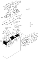
- the secondary battery 10 as a power storage device includes a case 11, and an electrode assembly 12 is accommodated in the case 11.
- the case 11 includes a square box-shaped case member 14 and a lid member 15 as a rectangular flat plate-like wall portion that closes the opening 14 a of the case member 14.
- the secondary battery 10 of this embodiment is a lithium ion battery.
- the electrode assembly 12 includes a plurality of sheet-like positive electrodes 21 and a plurality of sheet-like negative electrodes 31, and the positive electrodes 21 and the negative electrodes 31 are electrodes having different polarities.
- the positive electrode 21 has a positive metal foil (in this embodiment, an aluminum foil) and a positive electrode active material layer present on both surfaces of the positive metal foil.
- the negative electrode 31 has a negative electrode metal foil (copper foil in this embodiment) and a negative electrode active material layer present on both surfaces of the negative electrode metal foil.
- the electrode assembly 12 is a layered type in which a separator 24 is interposed between a plurality of positive electrodes 21 and a plurality of negative electrodes 31 to interpose them.
- the positive electrode 21 has a tab 25 having a shape protruding from a part of one side 21 a of the positive electrode 21.
- the negative electrode 31 has a tab 35 having a shape protruding from a part of one side 31 a of the negative electrode 31.
- the plurality of positive electrode tabs 25 and the plurality of negative electrode tabs 35 are respectively provided at positions where the positive electrode tab 25 and the negative electrode tab 35 do not overlap with each other in a state where the positive electrode 21 and the negative electrode 31 are stacked.
- the electrode assembly 12 has a tab side end face 12b formed by gathering together one side 21a of the positive electrode 21, one side 31a of the negative electrode 31, and one side of the separator 24.
- the positive electrodes 21 constituting the electrode assembly 12 are stacked such that the tabs 25 are arranged in a row along the stacking direction.
- the negative electrodes 31 constituting the electrode assembly 12 are stacked such that the tabs 35 are arranged in a row along the stacking direction.
- the secondary battery 10 includes a positive electrode tab group 36 protruding from the tab side end face 12b.
- the tab group 36 gathers all the positive electrode tabs 25 together on one side in the stacking direction of the electrode assembly 12, Configured.
- the secondary battery 10 has a negative electrode tab group 36 protruding from the tab side end face 12 b, and this tab group 36 gathers all the negative electrode tabs 35 to one side in the stacking direction in the electrode assembly 12. It is configured by stacking.
- the inner surface of the lid member 15 as the wall portion of the case 11 faces the tab groups 36 accommodated in the case 11 and the tab side end surface 12 b of the electrode assembly 12.
- the direction connecting the inner surface of the lid member 15 and the tab side end surface 12b of the electrode assembly 12 with the shortest distance is defined as a facing direction Z.
- a positive electrode conductive member 51 for electrically connecting the electrode assembly 12 and a positive electrode terminal structure 16 described later is joined to the positive electrode tab group 36. Further, the negative electrode tab group 36 is joined with a negative electrode conductive member 52 for electrically connecting the electrode assembly 12 and a negative electrode terminal structure 17 described later.
- a positive electrode conductive member 51 and a negative electrode conductive member 52 are disposed between the inner surface of the lid member 15 and the tab side end surface 12 b of the electrode assembly 12.
- the positive electrode conductive member 51 is joined to the tab group 36 and includes a substantially U-shaped tab joint portion 51a on one side in the longitudinal direction. Further, the positive electrode conductive member 51 includes a flat plate terminal connection portion 51b connected to the positive electrode lead terminal 60 described later on the other side in the longitudinal direction, and the tab joint portion 51a and the terminal connection portion 51b are continuous in the longitudinal direction. .
- the negative electrode conductive member 52 includes a substantially U-shaped tab joint portion 52 a electrically joined to the tab group 36 on one side in the longitudinal direction. Further, the negative electrode conductive member 52 includes a terminal connection portion 52b electrically connected to a negative electrode lead terminal 61, which will be described later, on the other side in the longitudinal direction, and the tab joint portion 52a and the terminal connection portion 52b are continuous in the longitudinal direction. .
- the lid member 15 has an outer surface 15c facing the outer side of the case 11 and an inner surface 15d facing the inner side of the case 11.
- a direction connecting the outer surface 15c and the inner surface 15d with the shortest distance is a thickness direction.
- the lid member 15 includes locking recesses 18 on both sides in the longitudinal direction. Each locking recess 18 has a shape recessed from the outer surface 15c along the thickness direction. When the lid member 15 is viewed from the outer surface 15c, the outer shape of the locking recess 18 is a square shape.
- the lid member 15 includes a protrusion 19 protruding from the inner surface 15d.
- the protrusion 19 has a shape protruding from the inner surface 15d by denting the locking recess 18, and the outer shape of the protrusion 19 is a quadrangular shape.
- the lid member 15 is provided with insertion holes 15e outside the respective locking recesses 18 in the longitudinal direction.
- the positive terminal structure 16 and the negative terminal structure 17 include an outer insulating member 57 disposed on the outer surface 15 c of the lid member 15.
- the outer insulating member 57 insulates the positive external connection terminal 66 and positive electrode lead terminal 60 from the lid member 15 and insulates the negative external connection terminal 66 and negative electrode lead terminal 61 from the lid member 15.
- the outer insulating member 57 is made of synthetic resin.
- the outer insulating member 57 has a rectangular shape when viewed from the outer surface 15 c of the lid member 15.
- the direction connecting the front surface 57c and the back surface 57a of the outer insulating member 57 is the thickness direction.
- the outer insulating member 57 includes a detent portion 58 that protrudes in the thickness direction from the back surface 57a near one end in the longitudinal direction.
- the anti-rotation part 58 has a shape protruding in a square hole shape from the front surface 57c toward the back surface 57a.
- the square shape formed by connecting the four outer surfaces of the rotation stopper 58 is similar to the square shape formed by connecting the four inner surfaces of the locking recess 18 of the lid member 15.
- the outer insulating member 57 is installed on the lid member 15 in a state where the rotation stopper 58 is inserted into the locking recess 18.
- the four outer surfaces of the rotation stopper 58 are in contact with and locked with the four inner surfaces of the locking recess 18.
- the outer insulating member 57 includes an insertion hole 57d near the end on the opposite side to the rotation stopper 58 in the longitudinal direction.
- the insertion hole 57d is at a position that coincides with the insertion hole 15e of the lid member 15.
- the positive electrode terminal structure 16 and the negative electrode terminal structure 17 include an external connection terminal 66 arranged outside the lid member 15, and the external connection terminal 66 can fix the bus bar outside the lid member 15.
- the external connection terminal 66 is made of metal.
- the external connection terminal 66 includes a prism-shaped bolt head 67, a shaft 68 having a shape protruding from one end surface of the bolt head 67 along the axial direction of the external connection terminal 66, and the other end surface of the bolt head 67. And an engaging projection 69 having a shape protruding from the projection.
- a nut for fastening a bus bar can be screwed onto the shaft portion 68.
- the engaging projection 69 has a quadrangular shape when viewed in the axial direction.
- the quadrangular shape formed by connecting the four outer surfaces of the engaging convex portion 69 is similar to the quadrangular shape formed by connecting the four inner surfaces of the anti-rotation portion 58 of the outer insulating member 57.
- the engaging convex portion 69 of the external connection terminal 66 is inserted into the rotation preventing portion 58 of the outer insulating member 57.
- the four outer surfaces of the engaging convex portion 69 are in contact with the four inner surfaces of the rotation preventing portion 58. By this contact, the movement of the external connection terminal 66 in the direction along the surface 57c of the outer insulating member 57 is restricted, and in particular, the rotation on the surface 57c of the outer insulating member 57 is restricted.
- the positive electrode terminal structure 16 includes a positive electrode lead terminal 60 as an electrode terminal electrically connected to the positive electrode tab group 36 of the electrode assembly 12 via the positive electrode conductive member 51.
- the negative electrode terminal structure 17 includes a negative electrode lead terminal 61 as an electrode terminal electrically connected to the negative electrode tab group 36 of the electrode assembly 12 via the negative electrode conductive member 52.
- the positive electrode lead terminal 60 includes a connecting shaft portion 60 a that is electrically connected to a terminal connection member 44 described later and a base portion 60 b that is electrically connected to the terminal connection portion 51 b of the positive electrode conductive member 51 in the axial direction.
- the terminal connection member 44 includes a connection piece 46 connected to the external connection terminal 66 on one side in the longitudinal direction, and a fixed piece 47 on the other side in the longitudinal direction.
- the terminal connection member 44 includes a through hole 46a that penetrates the connection piece 46 in the thickness direction, and the shaft portion 68 of the external connection terminal 66 is inserted into the through hole 46a.
- the terminal connection member 44 includes an insertion hole 47a that penetrates the fixed piece 47 in the thickness direction.
- a base portion 60b of the positive electrode lead terminal 60 is disposed so as to protrude from the inner surface 15d of the lid member 15 into the case 11, and a connecting shaft portion 60a includes an insertion hole 51c of the positive electrode conductive member 51, an inner insulation described later.
- the insertion hole 40 a of the member 40, the insertion hole 15 e of the lid member 15, the insertion hole 57 d of the outer insulating member 57, and the insertion hole 47 a of the terminal connection member 44 are penetrated.
- the positive electrode terminal structure 16 includes an O-ring 73, and a connecting shaft portion 60 a for the positive electrode lead terminal 60 is inserted into the O-ring 73, and the O-ring 73 is connected to the terminal connection portion 51 b of the positive electrode conductive member 51. It is supported. Further, the positive electrode terminal structure 16 includes the above-described inner insulating member 40 through which the connecting shaft portion 60a is inserted.
- the inner insulating member 40 has a square plate shape. The dimension of the inner insulating member 40 along the short direction of the lid member 15 is larger than the dimension of the positive electrode conductive member 51 along the short direction of the lid member 15. Therefore, the inner insulating member 40 protrudes from the positive electrode conductive member 51 along the short direction of the lid member 15.
- an O-ring 73 supported by the terminal connection portion 51 b is disposed inside the inner insulating member 40.
- the inner insulating member 40 is interposed between the lid member 15 and the terminal connection portion 51b, restricts the contact between the lid member 15 and the terminal connection portion 51b, and insulates the lid member 15 from the positive electrode conductive member 51. To do.
- the tip end portion of the connecting shaft portion 60a penetrating the insertion hole 47a of the terminal connecting member 44 is caulked in the axial direction, whereby the positive electrode conductive member 51, the inner insulating member 40, and the lid member are connected by the connecting shaft portion 60a and the base portion 60b. 15, the outer insulating member 57 and the fixing piece 47 of the terminal connection member 44 are sandwiched.
- the positive electrode lead terminal 60 is fixed to the lid member 15 by this clamping.
- the O-ring 73 is in close contact with the periphery of the insertion hole 15 e in the inner surface 15 d of the lid member 15 and seals the insertion hole 15 e of the lid member 15.
- the tip end portion of the connecting shaft portion 60a of the positive electrode lead terminal 60 is locked to the surface of the fixing piece 47 in the terminal connection member 44, and the positive electrode lead terminal 60 and the terminal connection member 44 are electrically connected by this lock. It is connected. Further, the base portion 60 b of the positive electrode lead terminal 60 contacts the terminal connection portion 51 b of the positive electrode conductive member 51, and the positive electrode lead terminal 60 and the positive electrode conductive member 51 are electrically connected by this contact.
- the negative electrode lead terminal 61 includes a connection shaft portion 62 that is electrically connected to the negative electrode terminal connection member 44, and a base portion 63 that is electrically connected to the terminal connection portion 52 b of the negative electrode conductive member 52.
- the connecting shaft portion 62 of the negative electrode lead terminal 61 is inserted into the insertion hole 40 a of the inner insulating member 40, the insertion hole 15 e of the lid member 15, the insertion hole 57 d of the outer insulating member 57, and the insertion hole 47 a of the terminal connection member 44. Yes.
- the base 63 of the negative electrode lead terminal 61 has a quadrangular prism shape.
- the outer shape of the base 63 is a square shape when the negative electrode lead terminal 61 is viewed from the axial direction.
- the negative electrode lead terminal 61 includes a shaft hole 64 penetrating in the axial direction, and the shaft hole 64 passes through the connecting shaft portion 62 and the base portion 63.
- the negative electrode lead terminal 61 includes a terminal end surface 63b on an end surface of the base 63 facing the tab side end surface 12b of the electrode assembly 12, and a recess 63c that is recessed from the terminal end surface 63b toward the connecting shaft portion 62. Prepare.
- the recess 63 c communicates with the shaft hole 64.
- the terminal end surface 63b has an annular shape surrounding the recess 63c.
- the negative electrode terminal structure 17 has an O-ring 73, and a connecting shaft portion 62 is inserted into the O-ring 73, and the O-ring 73 is supported by the base 63.
- the negative electrode terminal structure 17 includes a cylindrical inner insulating member 40 through which the connecting shaft portion 62 is inserted.
- An O-ring 73 supported by the base 63 is disposed inside the inner insulating member 40.
- the inner insulating member 40 is interposed between the lid member 15 and the base portion 63 of the negative electrode extraction terminal 61, restricts the contact between the lid member 15 and the base portion 63, and includes the lid member 15 and the negative electrode extraction terminal 61. Insulate.
- the negative inner insulating member 40 covers the outer peripheral surface of the base 63 and insulates the negative lead terminal 61 from the case 11.
- the distal end portion of the connecting shaft portion 62 penetrating the insertion hole 47 a of the terminal connecting member 44 is caulked in the axial direction, whereby the inner insulating member 40, the lid is covered by the connecting shaft portion 62 and the base portion 63.
- the member 15, the outer insulating member 57, and the terminal connection member 44 are sandwiched.
- the O-ring 73 is in close contact with the periphery of the insertion hole 15 e in the inner surface 15 d of the lid member 15 and seals the insertion hole 15 e of the lid member 15.
- the distal end portion of the connecting shaft portion 62 of the negative electrode lead terminal 61 is locked to the surface of the fixing piece 47 of the terminal connection member 44, and the negative electrode lead terminal 61 and the terminal connection member 44 are electrically connected by this lock. It is connected.
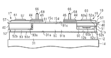
- the secondary battery 10 includes a current interrupt mechanism 80 electrically connected to a negative electrode lead terminal 61 as a first electrode terminal.
- the positive electrode lead terminal 60 is a second electrode terminal.
- the current interrupting mechanism 80 is disposed inside the case 11, and when the internal pressure of the case 11 reaches a predetermined set pressure, the energization that electrically connects the electrode assembly 12 and the negative electrode lead terminal 61. Cut off the current in the path.
- the current interrupt mechanism 80 is located at the base 63 of the negative electrode lead terminal 61 and the connection part of the terminal connection part 52 b of the negative electrode conductive member 52.
- the current interruption mechanism 80 is integrally incorporated in the negative electrode lead terminal 61.
- the base 63 of the negative electrode lead terminal 61 is electrically connected to the negative electrode conductive member 52 via the current interrupt mechanism 80, and the negative electrode conductive member 52 is electrically connected to the negative electrode tab group 36.
- an energization path between the electrode assembly 12 and the negative electrode extraction terminal 61 is configured.
- the current interruption mechanism 80 When the current interruption mechanism 80 is operated by the gas generated inside the case 11, the electric connection between the base portion 63 of the negative electrode lead terminal 61 and the negative electrode conductive member 52 is interrupted. That is, the current interruption mechanism 80 constitutes a part of the energization path when not operating, and interrupts the energization path when activated by receiving the pressure of the gas generated inside the case 11.
- the current interrupting mechanism 80 has a contact plate 81 joined to the terminal connection part 52 b and the base part 63 of the negative electrode conductive member 52.
- the contact plate 81 is made of a conductive material and has a bowl shape that protrudes toward the electrode assembly 12.
- the contact plate 81 covers the recess 63c of the base 63 from the electrode assembly 12 side.
- the outer peripheral portion of the contact plate 81 that protrudes from the recess 63c and the terminal end surface 63b of the base 63 are fixed by welding.
- the portion of the contact plate 81 that faces the recess 63c is convex toward the electrode assembly 12 (downward) in the normal state, and the portion that is convex toward the electrode assembly 12 and the negative electrode conductive member 52.
- the terminal connection portion 52b is welded.
- the negative electrode welded portion P which is a welded portion between the contact plate 81 and the terminal connection portion 52b, is a conductive portion that conducts the negative electrode lead terminal 61 and the negative electrode conductive member 52. Therefore, the negative electrode conductive member 52 and the negative electrode lead terminal 61 are electrically connected via the contact plate 81.
- the current interrupt mechanism 80 includes an insulating ring 82 disposed between the base 63 and the negative electrode conductive member 52, and a seal ring 83 disposed on the outer peripheral side of the insulating ring 82.
- the negative electrode conductive member 52 has a deformation recess 53a on the surface of the terminal connection portion 52b facing the electrode assembly 12.
- the deformation recess 53 a is recessed in a mortar shape from the electrode assembly 12 toward the lid member 15.
- the negative electrode weld portion P is located on the bottom surface of the deformation recess 53a.
- the terminal connection portion 52b has a fracture groove (not shown) at a portion that becomes the bottom surface of the deformation recess 53a.
- the fracture groove has an annular shape surrounding the negative electrode welded portion P.
- the current interruption mechanism 80 has a deformation plate 85 that receives the internal pressure of the case 11 and deforms.
- the deformation plate 85 is a diaphragm made of an elastic material, for example, a metal plate, and is disposed at a position closer to the electrode assembly 12 than the terminal connection portion 52b.
- the deformation plate 85 has a disk shape and covers the deformation concave portion 53a from the electrode assembly 12 side.
- the outer peripheral portion of the deformable plate 85 and the terminal connection portion 52b are fixed by welding over the entire periphery of the outer peripheral portion of the deformable plate 85.
- the deformation plate 85 airtightly separates the inside of the case 11 from the outside of the case 11.
- the deformable plate 85 is convex from the lid member 15 side toward the electrode assembly 12 side (downward), and a portion of the convex portion facing the negative electrode welded portion P is directed to the lid member 15. And has a protrusion 85a protruding.
- the protrusion 85a is made of an insulating material and faces the negative electrode welded portion P surrounded by the fracture groove.
- the internal pressure of the case 11 acts on one surface of the deformation plate 85 (the surface facing the electrode assembly 12). Further, external pressure (substantially atmospheric pressure) of the case 11 acts on the other surface of the deformation plate 85 (surface facing the lid member 15) via the shaft hole 64 of the negative electrode lead terminal 61.
- the deformation plate 85 is configured to be deformed by the pressure and protrude toward the lid member 15 when an internal pressure that reaches the set pressure is applied to the surface facing the electrode assembly 12. Yes.
- the deformation plate 85 is deformed toward the lid member 15, and the protrusion 85 a is formed between the terminal connection portion 52 b and the contact plate.
- the negative electrode weld part P with 81 is fractured. As a result, the electrical connection between the negative electrode lead terminal 61 and the negative electrode conductive member 52 is interrupted, and the current in the energization path is interrupted.
- the insulating cover 90 in the case 11 will be described.
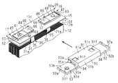
- the insulating cover 90 includes a positive electrode conductive member 51, a negative electrode conductive member 52, and a conductive member insulating portion 91 interposed between the lid member 15 in the facing direction Z.
- the insulating cover 90 includes a mechanism insulating portion 93 that insulates the negative electrode lead terminal 61 including the current interruption mechanism 80 from the tab side end surface 12 b of the electrode assembly 12, and the positive electrode lead terminal 60 and the tab of the electrode assembly 12.
- a terminal insulating portion 92 that insulates the side end face 12b.
- the insulating cover 90 is substantially U-shaped in a side view along the longitudinal direction.
- the mechanism insulating portion 93 is integrated with one end portion in the longitudinal direction of the rectangular conductive member insulating portion 91, and the terminal insulating portion 92 is the other end portion in the longitudinal direction of the conductive member insulating portion 91. It is integral. That is, the conductive member insulating portion 91, the terminal insulating portion 92, and the mechanism insulating portion 93 are formed of a single member.
- the conductive member insulating portion 91 is L-shaped in a side view as viewed along the longitudinal direction, and has a shape protruding toward the electrode assembly 12 from the insulating portion main body 91a and one long edge portion of the insulating portion main body 91a. Side wall portion 91b.
- the longitudinal direction of the insulating cover 90 is along the juxtaposed direction.
- a dimension of a straight line connecting the opposing surfaces of the pair of inner insulating members 40 along the juxtaposed direction is defined as a dimension N.
- the dimension of the conductive member insulating portion 91 in the longitudinal direction is slightly longer than the dimension N. For this reason, one end surface of both end surfaces in the longitudinal direction of the conductive member insulating portion 91 can contact the inner surface of the positive inner insulating member 40, and the other end surface can contact the inner surface of the negative inner insulating member 40. It is in a position where it can touch.
- the dimension in the short direction of the conductive member insulating portion 91 is slightly longer than the dimension in the short direction of the tab joint portions 51a and 52a.
- the insulating portion main body 91a of the conductive member insulating portion 91 is interposed between the positive and negative tab joint portions 51a and 52a in the facing direction Z and the lid member 15, and the tab joint portions 51a and 52a and the lid member 15 are interposed. And insulate. Further, the side wall portion 91 b of the conductive member insulating portion 91 is interposed between each tab group 36 and the inner surface of the long side wall of the case member 14 to insulate each tab group 36 from the case member 14.
- the insulating cover 90 includes housing recesses 91f at both longitudinal ends of the insulating body 91a.
- the housing recess 91 f has a shape that is recessed in a square shape from the outer surface 91 c of the insulating portion main body 91 a toward the electrode assembly 12.
- the protrusions 19 of the lid member 15 are inserted into the respective housing recesses 91f, and in the longitudinal direction and the short direction of the insulating cover 90 due to the contact between the outer surface of the protrusions 19 and the inner surface of the housing recess 91f.
- the movement of the insulating cover 90 along is restricted.
- the insulating cover 90 includes a connecting portion 94 that is integral with both ends in the longitudinal direction of the side wall 91 b of the conductive member insulating portion 91 and at one end in the short direction. And the mechanism insulation part 93 is connected with the connection part 94 of the longitudinal direction one end, and the terminal insulation part 92 is connected with the connection part 94 of the longitudinal direction other end of the side wall part 91b.
- the insulating portion main body 91a and the terminal insulating portion 92, and the insulating portion main body 91a and the mechanism insulating portion 93 are separated in the facing direction Z by the connecting portion 94.
- the insulating portion main body 91 a includes an inner surface 91 d on a surface facing the tab side end surface 12 b of the electrode assembly 12.
- the terminal insulating portion 92 has a quadrangular shape when viewed from the outer surface 15 c of the lid member 15.
- the planar view size of the terminal insulating portion 92 is larger than the planar view size of the base portion 60b of the positive electrode lead terminal 60, and the entire base portion 60b can be covered from the electrode assembly 12 side.
- the terminal insulating portion 92 includes an inner surface 92b that faces the base portion 60b of the positive electrode lead terminal 60 and an outer surface 92d that faces the tab-side end surface 12b of the electrode assembly 12, and the outer surface 92d is flat.
- the terminal insulating portion 92 includes a protruding portion 92e near the insulating portion main body 91a in the inner surface 92b, and the protruding portion 92e exists over the entire short side direction of the insulating cover 90. Further, the protruding portion 92e is located closer to the terminal insulating portion 92 than the insulating portion main body 91a. In the facing direction Z, the insulating portion main body 91a and the protruding portion 92e do not overlap and are displaced in the longitudinal direction. .
- the insulating cover 90 includes a positive electrode side gap 95a between the insulating body 91a and the protrusion 92e in the facing direction Z.
- the positive electrode side gap 95a is connected to the connecting portion 94 in the short direction of the insulating cover 90. Open at the opposite end.
- the dimension of the positive electrode side gap 95a along the facing direction Z is larger than the thickness of the positive electrode conductive member 51, and the terminal connection portion 51b is inserted into the positive electrode side gap 95a.
- the terminal insulating portion 92 includes a rib 92 g at a position that becomes the longitudinal end portion of the insulating cover 90. The rib 92g exists over the entire short side direction of the insulating cover 90.
- the insulating portion main body 91a of the insulating cover 90 is supported by the tab joint portion 51a of the positive electrode conductive member 51, and the insulating portion main body 91a is sandwiched between the tab joint portion 51a and the lid member 15 along the facing direction Z. ing.
- the connecting portion 94 is located at one end portion of the protruding portion 92e, and the locking claw 92a is present at the other end portion.
- the locking claw 92a of the terminal insulating portion 92 protrudes in the facing direction Z from the protruding portion 92e.
- the dimension between the opposing surfaces of the connecting part 94 and the protrusion 92e along the short direction of the insulating cover 90 is larger than the dimension of the positive electrode conductive member 51 along the short direction and slightly larger than the dimension of the inner insulating member 40 of the positive electrode. long.
- the connecting portion 94 comes into contact with one of the edges of the inner insulating member 40 facing the short side of the insulating cover 90, and FIG. ), The locking claw 92a is locked to the other edge.
- the tip surface of the rib 92g along the facing direction Z is in contact with the surface of the inner insulating member 40 facing the electrode assembly 12.
- the mechanism insulating portion 93 has a quadrangular shape when viewed from the outer surface 15 c of the lid member 15.
- the size in plan view of the mechanism insulating portion 93 is substantially the same as the size in plan view of the base 63 of the negative electrode lead terminal 61 and the current interrupt mechanism 80, and the entire current interrupt mechanism 80 can be covered from the electrode assembly 12 side.
- the mechanism insulating portion 93 includes an inner surface 93 b that faces the deformation plate 85 of the current interrupt mechanism 80, an outer surface 93 d that faces the electrode assembly 12, and the outer surface 93 d has a flat surface shape.
- the mechanism insulating portion 93 includes a protrusion 93e on the inner surface 93b near the insulating portion main body 91a, and the protrusion 93e exists over the entire short side direction of the insulating cover 90. In the facing direction Z, the insulating portion main body 91a and the protruding portion 93e are in overlapping positions.
- the insulating cover 90 includes a negative electrode side gap 95b between the insulating main body 91a and the protrusion 93e in the facing direction Z.
- the negative electrode side gap 95b is opposite to the connecting portion 94 in the short direction of the insulating cover 90. Open at the end.
- the dimension of the negative electrode side gap 95b along the facing direction Z is larger than the thickness of the tab joint portion 52a of the negative electrode conductive member 52, and the negative electrode tab joint portion 52a is inserted into the negative electrode side gap 95b.
- the insulating portion main body 91a of the insulating cover 90 is supported by the tab joint portion 52a, and the insulating portion main body 91a is sandwiched between the tab joint portion 52a and the lid member 15 along the facing direction Z.
- the mechanism insulating portion 93 includes a rib 93g along the edge of the inner surface 93b, and the rib 93g is L-shaped in plan view.
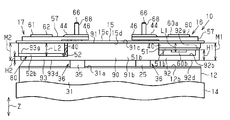
- the dimension from the outer surface 92d of the terminal insulating portion 92 to the tip end surface of the rib 92g is the height H1
- the outer surface 93d of the mechanism insulating portion 93 to the tip end surface of the rib 93g is the height H2.
- the height H1 of the rib 92g of the terminal insulating portion 92 is higher than the height H2 of the rib 93g of the mechanism insulating portion 93.
- the connecting portion 94 is located at one end of the negative-side protrusion 93e and the engaging claw 93a at the other end of the both ends along the short direction of the insulating cover 90.
- the locking claw 93a of the mechanism insulating portion 93 protrudes in the facing direction Z from the protruding portion 93e.
- the dimension between the opposing surfaces of the connecting portion 94 and the protrusion 93e along the short direction of the insulating cover 90 is slightly larger than the dimension along the short direction of the tab joint portion 52a.
- the connecting portion 94 abuts on one of the edge portions of the tab joint portion 52a facing the short side direction of the insulating cover 90, and the other edge portion.
- the latching claw 93a is latched to the.
- the tip surface of the rib 93g along the facing direction Z is in contact with the surface facing the electrode assembly 12 in the terminal connection portion 52b.
- the mechanism insulating portion 93 is provided with an escape recess 93f penetrating in the thickness direction at the center, and the deformation plate 85 of the current interrupt mechanism 80 enters the escape recess 93f. Yes.
- the internal pressure of the case 11 acts on the lower surface of the deformable plate 85 (the surface facing the electrode assembly 12) via the relief recess 93f.
- the height H2 from the outer surface 93d to the leading end surface of the rib 93g is lower than the height H1 from the outer surface 92d to the leading end surface of the rib 92g in the terminal insulating portion 92.
- the dimension L1 from the inner surface 15d of the lid member 15 to the base portion 60b of the positive electrode lead terminal 60 along the facing direction Z is from the inner surface 15d of the lid member 15 to the terminal connection portion 52b including the current interruption mechanism 80. It is smaller than the dimension L2.
- the rib 93 g of the mechanism insulating portion 93 is in contact with the terminal connecting portion 52 b, and the rib 92 g of the terminal insulating portion 92 is in contact with the terminal connecting portion 51 b of the positive electrode conductive member 51.
- the dimension from the inner surface 15d of the lid member 15 to the outer surface 92d of the terminal insulating portion 92 is defined as a protruding dimension M1 of the positive electrode terminal structure 16.
- a dimension from the inner surface 15d of the lid member 15 to the outer surface 93d of the mechanism insulating portion 93 is defined as a protruding dimension M2 of the negative electrode terminal structure 17.
- the protruding dimension M2 in the negative electrode terminal structure 17 and the protruding dimension M1 in the positive electrode terminal structure 16 are the same.
- the distance between the outer surface 92d of the terminal insulating portion 92 and the tab side end surface 12b of the electrode assembly 12 is the same as the distance between the outer surface 93d of the mechanism insulating portion 93 and the tab side end surface 12b of the electrode assembly 12. It is.
- the outer surface 92 d of the terminal insulating part 92 is flush with the outer surface 93 d of the mechanism insulating part 93.
- the current interruption mechanism 80 is not integrated with the base portion 60 b of the positive electrode extraction terminal 60, but in the negative electrode terminal structure 17, the current interruption mechanism 80 is integrated with the base portion 63 of the negative electrode extraction terminal 61. Yes.
- the negative electrode terminal structure 17 protrudes from the lid member 15 toward the electrode assembly 12, and the dimension L2 of the negative electrode terminal structure 17 is larger than the dimension L1 of the positive electrode terminal structure 16.
- the height H2 of the mechanism insulating portion 93 is made lower than the height H1 of the terminal insulating portion 92, and the difference in the protruding dimensions of the positive terminal structure 16 and the negative terminal structure 17 from the lid member 15 is determined by the insulating cover.
- the outer surface 93d of the mechanism insulating part 93 and the outer surface 92d of the terminal insulating part 92 are flush with each other while the insulating cover 90 covers the current interrupting mechanism 80 from the electrode assembly 12 side.
- a contact plate 81 is joined to the terminal end face 63b of the negative electrode lead terminal 61 of the negative electrode, and the contact plate 81, the insulating ring 82, the seal ring 83, and the negative electrode conductive member 52 (terminal connection portion 52b) are unitized. Shall. Further, it is assumed that the deformable plate 85 is joined to the terminal connection portion 52b of the negative electrode conductive member 52, and the negative electrode lead terminal 61, the current interruption mechanism 80, and the negative electrode conductive member 52 are integrated in advance.
- the outer insulating member 57 is disposed on the outer surface 15 c of the lid member 15 in a state in which the detents 58 of the outer insulating member 57 are inserted into the respective locking recesses 18 of the lid member 15.
- the engaging projection 69 of the external connection terminal 66 is inserted into the rotation stopper 58 of the outer insulating member 57.
- the shaft portion 68 of the external connection terminal 66 is inserted into the through hole 46 a of the terminal connection member 44.
- the O-ring 73 and the inner insulating member 40 are disposed on the inner surface 15d side of the lid member 15 and the positive electrode conductive member 51 is disposed.
- the connecting shaft portion 62 of the positive electrode lead terminal 60 is connected to the positive electrode conductive member 51.
- the positive electrode conductive member 51, the inner insulating member 40, the lid member 15, and the outer insulating member 57 are interposed between the base portion 60b and the distal end portion of the connecting shaft portion 60a by caulking the connecting shaft portion 60a of the positive electrode lead terminal 60.
- the terminal connection member 44 are integrated.
- the O-ring 73 and the inner insulating member 40 are arranged on the inner surface 15 d side of the lid member 15, and the insertion hole 40 a of the inner insulating member 40, the O-ring 73, the insertion hole 15 e of the lid member 15, and the terminal connection member 44.
- the connecting shaft portion 62 of the negative electrode lead terminal 61 is inserted into the insertion hole 47a.
- the inner insulating member 40, the lid member 15, the outer insulating member 57, and the terminal connecting member 44 are integrated between the base 63 and the distal end portion of the connecting shaft portion 62 by caulking the connecting shaft portion 62.
- the current interrupt mechanism 80 is also integrated.
- the positive terminal structure 16 and the negative terminal structure 17 are formed on the lid member 15, and the lid terminal assembly 20 is formed.
- the outer insulating member 57 is rotated on the lid member 15 by the engagement between the outer surface of the rotation preventing portion 58 of the outer insulating member 57 and the inner surface of the locking recess 18 of the lid member 15. Is regulated.
- the rotation of the external connection terminal 66 is restricted by the engagement between the inner surface of the rotation stopper 58 of the outer insulating member 57 whose rotation is restricted and the outer surface of the engagement projection 69 of the external connection terminal 66.
- the lid terminal assembly 20 there is a gap between the lid member 15 and the tab joints 51a and 52a in the facing direction Z. Further, the tab joint portions 51 a and 52 a are L-shaped, and the tab joint portions 51 a and 52 a have a portion protruding from the lid member 15.
- the positive electrode tab group 36 of the electrode assembly 12 is joined to the tab joint portion 51 a of the positive electrode conductive member 51 by laser welding, and the negative electrode tab group 36 is laser-bonded to the tab joint portion 52 a of the negative electrode conductive member 52. Joined by welding. Then, the lid terminal assembly 20 and the electrode assembly 12 are integrated.
- the tab joint portions 51a and 52a are bent into a substantially U shape, and the tab group 36 is bent. And as shown in FIG. 7, while inserting the insulation part main body 91a of the insulation cover 90 between the cover member 15 and the tab junction parts 51a and 52a in the opposing direction Z, the positive electrode conductive member 51 is inserted into the positive electrode side gap 95a. Then, the insulating cover 90 is slid so as to insert the negative electrode conductive member 52 into the negative electrode side gap 95b.
- the insulating cover 90 is integrally assembled with the positive electrode conductive member 51 and the negative electrode conductive member 52, and the tab joint portions 51a and 52a are insulated from the lid member 15 by the insulating portion main body 91a.
- terminal insulating portion 92 insulates the base portion 60b of the positive electrode lead terminal 60 from the electrode assembly 12 and the mechanism insulating portion 93 insulates the current interruption mechanism 80 from the electrode assembly 12, while protecting the deformation plate 85.
- the electrode assembly 12 is inserted into the case member 14 from the opening 14 a of the case member 14.
- the lid terminal assembly 20 is pushed toward the case member 14 in order to push the electrode assembly 12 into the case member 14.
- the electrode assembly 12 Pressed is shown in FIG. 9, while the outer surface 92d of the terminal insulating portion 92 of the insulating cover 90 and the outer surface 93d of the mechanism insulating portion 93 are simultaneously in contact with the tab side end surface 12b of the electrode assembly 12, the electrode assembly 12 Pressed.
- the secondary battery 10 is assembled. According to the above embodiment, the following effects can be obtained.
- the projecting dimension M2 up to is the same. Therefore, when the secondary battery 10 is initially charged or when the secondary battery 10 is used, an external force acts on the secondary battery 10 or receives vibration, and the electrode assembly 12 moves toward the lid member 15. Then, the tab side end surface 12b of the electrode assembly 12 contacts both the terminal insulating portion 92 and the mechanism insulating portion 93.
- both the terminal insulation part 92 and the mechanism insulation part 93 are plate-shaped, and the outer surfaces 92d and 93d are flat surface shapes, the contact area with the tab side end surface 12b can be ensured widely. Therefore, for example, when the secondary battery 10 vibrates, the current interruption mechanism 80 can be prevented from locally contacting the tab side end surface 12b of the electrode assembly 12, and the tab side end surface 12b is not easily damaged.
- the terminal insulating portion 92 and the outer surface 92d of the mechanism insulating portion 93 with respect to the tab side end surface 12b. , 93d come into contact with each other, and the load applied to the electrode assembly 12 is dispersed. For this reason, when the electrode assembly 12 is inserted into the case member 14, the terminal insulating portion 92 and the mechanism insulating portion 93 are not locally in contact with the tab side end surface 12b, and the tab side end surface 12b is not easily damaged.
- the rib 92g of the terminal insulating part 92 is in contact with the inner insulating member 40, and in the negative electrode terminal structure 17, the rib 93g of the mechanism insulating part 93 is in contact with the terminal connecting part 52b.
- the height H1 at the rib 92g of the terminal insulating portion 92 is made higher than the height H2 at the rib 93g of the mechanism insulating portion 93. Due to the difference in height, the protruding dimension M1 of the positive terminal structure 16 and the negative terminal The protrusion dimension M2 of the structure 17 can be made the same.
- the deformation plate 85 of the current interruption mechanism 80 is covered from the electrode assembly 12 side by the mechanism insulating portion 93 of the insulating cover 90. For this reason, when the secondary battery 10 is initially charged or when the secondary battery 10 is used, even if an external force is applied to the secondary battery 10 or vibration is applied, the tab-side end surface 12b of the electrode assembly 12 is not affected.
- the contact with the deformation plate 85 can be restricted, the deformation of the deformation plate 85 can be suppressed, and the malfunction of the current interrupt mechanism 80 can be suppressed.
- the insulating cover 90 includes a conductive member insulating portion 91 that insulates the tab joint portions 51a and 52a and the lid member 15, a terminal insulating portion 92 that insulates the positive electrode lead terminal 60 from the electrode assembly 12, and a current interruption mechanism.
- a mechanism insulating portion 93 that insulates 80 from the electrode assembly 12 is integrally provided. Therefore, as compared with the case where the tab joining portions 51a and 52a and the insulating member of the lid member 15, the positive electrode lead terminal 60 and the insulating member of the electrode assembly 12, and the current interrupting mechanism 80 and the insulating member of the electrode assembly 12 are provided separately. And the number of parts of the secondary battery 10 can be reduced, and the assembly work of the secondary battery 10 becomes easy.
- the insulating cover 90 includes housing recesses 91f at both ends in the longitudinal direction of the insulating body 91a, and the protrusions 19 of the lid member 15 are inserted into the housing recesses 91f.
- the protrusion 19 is a portion into which the rotation preventing portion 58 of the outer insulating member 57 enters in order to restrict the rotation of the outer insulating member 57 on the lid member 15. Therefore, while the secondary battery 10 includes the protrusion 19 that restricts the rotation of the outer insulating member 57 on the lid member 15, the protrusion 19 does not interfere with the mounting state of the insulating cover 90.
- the insulating cover 90 is configured to integrally include the conductive member insulating portion 91, the terminal insulating portion 92, and the mechanism insulating portion 93. However, the conductive member insulating portion 91, the terminal insulating portion 92, and the mechanism insulating portion 93 are integrated. And may be separated.
- the rib 92g of the terminal insulating part 92 and the rib 93g of the mechanism insulating part 93 may be eliminated, and the protruding dimension M1 and the protruding dimension M2 may be the same depending on the thickness of the terminal insulating part 92 and the mechanism insulating part 93 itself.
- the insulating cover 90 may have a structure in which the conductive member insulating portion 91 does not exist and the terminal insulating portion 92 and the mechanism insulating portion 93 are integrated. In the insulating cover 90, if the mechanism insulating part 93 is separated along the facing direction Z so as not to contact the deformation plate 85 of the current interrupting mechanism 80, the relief recess 93f may be omitted.
- the power storage device can also be applied to a secondary battery having a current interruption mechanism 80 integrated with the positive electrode lead terminal 60.
- the mechanism insulating portion 93 is disposed between the positive electrode lead terminal 60 and the tab side end surface 12b of the electrode assembly 12, and the terminal insulating portion is disposed between the negative electrode lead terminal 61 and the tab side end surface 12b of the electrode assembly 12. 92 is arranged.
- the positive electrode lead terminal 60 corresponds to the first electrode terminal
- the negative electrode lead terminal 61 corresponds to the second electrode terminal.
- the wall portion may be the side wall of the case member 14 instead of the lid member 15.
- the electrode terminal may not be connected to the external connection terminal 66 via the terminal connection member 44 like the positive electrode lead terminal 60 or the negative electrode lead terminal 61, and may be connected to the positive electrode conductive member 51 or the negative electrode conductive member 52. It may be directly connected.
- the power storage device can also be applied to power storage devices other than secondary batteries, such as capacitors.
- the positive electrode 21 and the negative electrode 31 may have a structure in which an active material layer is present on one side of a metal foil.
- the secondary battery 10 may be a lithium ion secondary battery or another secondary battery. In short, any ion may be used as long as ions move between the active material for the positive electrode and the active material for the negative electrode and charge is transferred.
- An electrode assembly in which electrodes of different polarities are laminated while being insulated from each other, a tab having a shape protruding from the electrode, and a tab group of each polarity protruding from an end surface of the electrode assembly;
- a case accommodating the electrode assembly and the tab group; an external connection terminal disposed outside a wall portion of the case; and an end face of the electrode assembly and the wall portion, and the tab group.
- a power storage device comprising: a terminal connection member that is disposed outside and connecting the lead terminal and the external connection terminal; and an insulating cover that is interposed between the pair of conductive members and the wall portion.
- the external connection at the wall A portion that overlaps with the child is provided with a locking concave portion that prevents the engaging convex portion of the external connection terminal from rotating toward the insulating cover, and the insulating cover protrudes from the wall portion by the locking concave portion.
- a power storage device comprising a housing recess for housing the battery.
- the part which protruded from the wall part is a site
- Electrode assembly 12b ... Tab side end surface, 15 ... Lid member as wall, 21 ... Positive electrode, 31 ... Negative electrode Electrode 51 ... Positive electrode conductive member 52 ... Negative electrode conductive member 60 ... Positive electrode extraction terminal as second electrode terminal 61 ... Negative electrode extraction terminal as first electrode terminal 80 ... Current interruption mechanism 85 ... Deformation plate 91 ... conductive member insulating part, 92 ... terminal insulating part, 93 ... mechanism insulating part.
Landscapes
- Engineering & Computer Science (AREA)
- Power Engineering (AREA)
- Chemical & Material Sciences (AREA)
- Microelectronics & Electronic Packaging (AREA)
- General Chemical & Material Sciences (AREA)
- Chemical Kinetics & Catalysis (AREA)
- Electrochemistry (AREA)
- Manufacturing & Machinery (AREA)
- Materials Engineering (AREA)
- Connection Of Batteries Or Terminals (AREA)
- Electric Double-Layer Capacitors Or The Like (AREA)
- Cell Separators (AREA)
- Secondary Cells (AREA)
Abstract
Description
本発明の目的は、電極組立体への局所的な接触を抑制できる蓄電装置を提供することにある。
図1又は図3に示すように、蓄電装置としての二次電池10はケース11を備え、ケース11には電極組立体12が収容されている。ケース11は、四角箱状のケース部材14と、このケース部材14の開口部14aを閉塞する矩形平板状の壁部としての蓋部材15とを有している。なお、本実施形態の二次電池10はリチウムイオン電池である。
図4に示すように、絶縁カバー90は、対向方向Zにおいて正極導電部材51及び負極導電部材52と蓋部材15との間に介在する導電部材絶縁部91を備える。また、絶縁カバー90は、電流遮断機構80を含めた負極引出端子61と、電極組立体12のタブ側端面12bとを絶縁する機構絶縁部93と、正極引出端子60と電極組立体12のタブ側端面12bとを絶縁する端子絶縁部92とを備える。そして、絶縁カバー90は長手方向に沿う側面視略U字状である。
ここで、図2に示すように、端子絶縁部92の外面92dからリブ92gの先端面に至るまでの寸法を高さH1とし、機構絶縁部93の外面93dからリブ93gの先端面に至るまでの寸法を高さH2とする。端子絶縁部92のリブ92gの高さH1は、機構絶縁部93のリブ93gの高さH2より高い。
なお、負極の負極引出端子61の端子端面63bには接点板81が接合され、接点板81、絶縁リング82、シールリング83、及び負極導電部材52(端子接続部52b)がユニット化されているものとする。また、負極導電部材52の端子接続部52bには変形板85が接合されており、負極引出端子61と電流遮断機構80と負極導電部材52が予め一体化されているとする。
上記実施形態によれば、以下のような効果を得ることができる。
○ 絶縁カバー90が導電部材絶縁部91と、端子絶縁部92と、機構絶縁部93とを一体に備える構成であったが、導電部材絶縁部91と、端子絶縁部92と、機構絶縁部93とを別体としてもよい。
○ 絶縁カバー90において、電流遮断機構80の変形板85に接触しないように機構絶縁部93を対向方向Zに沿って離間させれば、逃がし凹部93fは無くてもよい。
○ 電極端子は、正極引出端子60や負極引出端子61のように、外部接続端子66と端子接続部材44を介して接続されるものでなくてもよく、正極導電部材51や負極導電部材52に直接接続されたものでもよい。
○ 正極電極21及び負極電極31は、金属箔の片面に活物質層が存在する構造でもよい。
(1)異なる極性の電極が互いに絶縁されて積層された状態の電極組立体と、前記電極から突出した形状のタブが積層され、前記電極組立体の端面から突出した各極性のタブ群と、前記電極組立体及び前記タブ群を収容したケースと、前記ケースの壁部の外側に配置された外部接続端子と、前記電極組立体の端面と前記壁部との間に配置され、前記タブ群と電気的に接続された導電部材と、前記タブ群の並設方向において該タブ群よりも外側で前記導電部材に接続され、前記壁部から外部に突出した状態の引出端子と、前記壁部の外側に配置され、かつ前記引出端子と前記外部接続端子とを接続した端子接続部材と、一対の前記導電部材と前記壁部との間に介在する絶縁カバーと、を備える蓄電装置であって、前記壁部における前記外部接続端子と重なる部分に、前記外部接続端子の係合凸部を回り止めする係止凹部を前記絶縁カバーに向けて突出して備え、前記絶縁カバーは、前記係止凹部によって前記壁部から突出した部分を収容する収容凹部を備えることを特徴とする蓄電装置。
Claims (4)
- 異なる極性の電極が互いに絶縁されて積層された状態の電極組立体と、
前記電極組立体を収容したケースと、
同じ極性の前記電極と電気的にそれぞれ接続され、前記ケースの壁部に固定された第1及び第2の電極端子と、
前記第1の電極端子と電気的に接続される電流遮断機構と、を備える蓄電装置であって、
前記電流遮断機構は、前記ケースの内部圧力が設定圧力に達すると、前記電極端子と前記電極組立体との間の電気的な通電経路の電流を遮断する構造を有し、
前記電流遮断機構を含めた前記第1の電極端子と前記電極組立体の前記端面とを絶縁する機構絶縁部と、
前記第2の電極端子と前記電極組立体の前記端面とを絶縁する端子絶縁部と、を備え、
前記壁部から前記第1の電極端子を含む前記機構絶縁部までの突出寸法と、
前記壁部から前記第2の電極端子を含む前記端子絶縁部までの突出寸法とが同じである蓄電装置。 - 同じ極性の前記電極と前記電極端子とを接続し、前記壁部と前記端面との間に配置された一対の導電部材を備えるとともに、一対の前記導電部材と前記壁部とを絶縁する導電部材絶縁部を備え、前記端子絶縁部及び前記機構絶縁部は、前記導電部材絶縁部と一体である、請求項1に記載の蓄電装置。
- 前記電流遮断機構は、一面に前記ケースの内部圧力が作用し、他面に前記ケースの外部圧力が作用する変形板を備え、かつ前記第1の電極端子と前記電極組立体との電気的な通電経路の一部を構成するとともに、前記電極組立体の端面と前記第1の電極端子との間に配置されている、請求項1又は請求項2に記載の蓄電装置。
- 前記蓄電装置は二次電池である、請求項1~3の何れか一項に記載の蓄電装置。
Priority Applications (5)
| Application Number | Priority Date | Filing Date | Title |
|---|---|---|---|
| US15/779,603 US10862098B2 (en) | 2015-12-24 | 2016-12-12 | Power storage device |
| DE112016006034.3T DE112016006034T5 (de) | 2015-12-24 | 2016-12-12 | Leistungsspeichervorrichtung |
| CN201680074658.4A CN108370020B (zh) | 2015-12-24 | 2016-12-12 | 蓄电装置 |
| KR1020187015979A KR102053560B1 (ko) | 2015-12-24 | 2016-12-12 | 축전 장치 |
| JP2017557881A JPWO2017110548A1 (ja) | 2015-12-24 | 2016-12-12 | 蓄電装置 |
Applications Claiming Priority (2)
| Application Number | Priority Date | Filing Date | Title |
|---|---|---|---|
| JP2015-251819 | 2015-12-24 | ||
| JP2015251819 | 2015-12-24 |
Publications (1)
| Publication Number | Publication Date |
|---|---|
| WO2017110548A1 true WO2017110548A1 (ja) | 2017-06-29 |
Family
ID=59090186
Family Applications (1)
| Application Number | Title | Priority Date | Filing Date |
|---|---|---|---|
| PCT/JP2016/086875 Ceased WO2017110548A1 (ja) | 2015-12-24 | 2016-12-12 | 蓄電装置 |
Country Status (6)
| Country | Link |
|---|---|
| US (1) | US10862098B2 (ja) |
| JP (1) | JPWO2017110548A1 (ja) |
| KR (1) | KR102053560B1 (ja) |
| CN (1) | CN108370020B (ja) |
| DE (1) | DE112016006034T5 (ja) |
| WO (1) | WO2017110548A1 (ja) |
Cited By (4)
| Publication number | Priority date | Publication date | Assignee | Title |
|---|---|---|---|---|
| JP2017117647A (ja) * | 2015-12-24 | 2017-06-29 | 株式会社豊田自動織機 | 蓄電装置 |
| JP2017117667A (ja) * | 2015-12-24 | 2017-06-29 | 株式会社豊田自動織機 | 蓄電装置 |
| JP2019125493A (ja) * | 2018-01-17 | 2019-07-25 | 三洋電機株式会社 | 二次電池 |
| EP3723154A4 (en) * | 2018-10-30 | 2021-04-07 | Contemporary Amperex Technology Co., Limited | UPPER PRESS PLATE, SECONDARY BATTERY AND SECONDARY BATTERY MANUFACTURING METHOD |
Families Citing this family (8)
| Publication number | Priority date | Publication date | Assignee | Title |
|---|---|---|---|---|
| CN114899557B (zh) * | 2017-01-25 | 2025-08-29 | 三洋电机株式会社 | 二次电池 |
| US11640880B2 (en) * | 2017-12-12 | 2023-05-02 | Gs Yuasa International Ltd. | Energy storage device |
| JP7001957B2 (ja) * | 2018-03-02 | 2022-01-20 | トヨタ自動車株式会社 | 電池の製造方法および電池 |
| EP4071923A4 (en) * | 2020-09-30 | 2023-08-23 | Contemporary Amperex Technology Co., Limited | BATTERY CELL, BATTERY, ELECTRICAL DEVICE, AND METHOD AND SYSTEM FOR MAKING A BATTERY CELL |
| CN116941075B (zh) * | 2021-12-15 | 2025-10-28 | 宁德时代新能源科技股份有限公司 | 集流构件、电池单体、电池及用电设备 |
| CN218472105U (zh) * | 2022-10-11 | 2023-02-10 | 湖北亿纬动力有限公司 | 电池盖板及动力电池 |
| JP7613452B2 (ja) * | 2022-11-10 | 2025-01-15 | トヨタ自動車株式会社 | 蓄電セル |
| KR20240076489A (ko) * | 2022-11-22 | 2024-05-30 | 삼성에스디아이 주식회사 | 이차 전지 |
Citations (10)
| Publication number | Priority date | Publication date | Assignee | Title |
|---|---|---|---|---|
| JP2004172085A (ja) * | 2002-11-15 | 2004-06-17 | Samsung Sdi Co Ltd | 二次電池用安全装置とそれを備えた二次電池 |
| JP2011086604A (ja) * | 2009-10-16 | 2011-04-28 | Sb Limotive Co Ltd | 2次電池 |
| JP2012054236A (ja) * | 2010-09-01 | 2012-03-15 | Sb Limotive Co Ltd | 2次電池 |
| US20120214050A1 (en) * | 2011-02-22 | 2012-08-23 | Dukjung Kim | Rechargeable battery |
| JP2014107147A (ja) * | 2012-11-28 | 2014-06-09 | Toyota Industries Corp | 蓄電装置 |
| JP2014127284A (ja) * | 2012-12-25 | 2014-07-07 | Toyota Motor Corp | 非水電解液二次電池 |
| JP2015095370A (ja) * | 2013-11-12 | 2015-05-18 | 株式会社豊田自動織機 | 蓄電装置 |
| JP2015115267A (ja) * | 2013-12-13 | 2015-06-22 | 株式会社豊田自動織機 | 電流遮断装置を備えた蓄電装置 |
| US20150263330A1 (en) * | 2014-03-11 | 2015-09-17 | Samsung Sdi Co., Ltd. | Rechargeable battery |
| JP2015167085A (ja) * | 2014-03-03 | 2015-09-24 | 株式会社豊田自動織機 | 蓄電装置 |
Family Cites Families (8)
| Publication number | Priority date | Publication date | Assignee | Title |
|---|---|---|---|---|
| KR100880385B1 (ko) | 2006-04-10 | 2009-01-23 | 주식회사 엘지화학 | 안전성을 향상시키는 절연부재를 포함하고 있는 이차전지 |
| CN102280654B (zh) * | 2010-06-11 | 2015-06-17 | 深圳市比克电池有限公司 | 一种锂离子电池 |
| JP5556629B2 (ja) | 2010-12-01 | 2014-07-23 | トヨタ自動車株式会社 | 密閉型電池 |
| US9537121B2 (en) * | 2011-03-18 | 2017-01-03 | Samsung Sdi Co., Ltd. | Secondary battery and secondary battery pack having a flexible collecting tab extending through a cap plate |
| JP5663415B2 (ja) * | 2011-06-24 | 2015-02-04 | 日立オートモティブシステムズ株式会社 | 二次電池 |
| JP5803713B2 (ja) | 2012-02-08 | 2015-11-04 | 株式会社豊田自動織機 | 蓄電装置及び車両 |
| US10014495B2 (en) * | 2013-05-15 | 2018-07-03 | Samsung Sdi Co., Ltd. | Rechargeable battery |
| JP6171943B2 (ja) * | 2014-01-15 | 2017-08-02 | 株式会社豊田自動織機 | 蓄電装置 |
-
2016
- 2016-12-12 KR KR1020187015979A patent/KR102053560B1/ko not_active Expired - Fee Related
- 2016-12-12 WO PCT/JP2016/086875 patent/WO2017110548A1/ja not_active Ceased
- 2016-12-12 CN CN201680074658.4A patent/CN108370020B/zh not_active Expired - Fee Related
- 2016-12-12 US US15/779,603 patent/US10862098B2/en not_active Expired - Fee Related
- 2016-12-12 DE DE112016006034.3T patent/DE112016006034T5/de not_active Withdrawn
- 2016-12-12 JP JP2017557881A patent/JPWO2017110548A1/ja not_active Withdrawn
Patent Citations (10)
| Publication number | Priority date | Publication date | Assignee | Title |
|---|---|---|---|---|
| JP2004172085A (ja) * | 2002-11-15 | 2004-06-17 | Samsung Sdi Co Ltd | 二次電池用安全装置とそれを備えた二次電池 |
| JP2011086604A (ja) * | 2009-10-16 | 2011-04-28 | Sb Limotive Co Ltd | 2次電池 |
| JP2012054236A (ja) * | 2010-09-01 | 2012-03-15 | Sb Limotive Co Ltd | 2次電池 |
| US20120214050A1 (en) * | 2011-02-22 | 2012-08-23 | Dukjung Kim | Rechargeable battery |
| JP2014107147A (ja) * | 2012-11-28 | 2014-06-09 | Toyota Industries Corp | 蓄電装置 |
| JP2014127284A (ja) * | 2012-12-25 | 2014-07-07 | Toyota Motor Corp | 非水電解液二次電池 |
| JP2015095370A (ja) * | 2013-11-12 | 2015-05-18 | 株式会社豊田自動織機 | 蓄電装置 |
| JP2015115267A (ja) * | 2013-12-13 | 2015-06-22 | 株式会社豊田自動織機 | 電流遮断装置を備えた蓄電装置 |
| JP2015167085A (ja) * | 2014-03-03 | 2015-09-24 | 株式会社豊田自動織機 | 蓄電装置 |
| US20150263330A1 (en) * | 2014-03-11 | 2015-09-17 | Samsung Sdi Co., Ltd. | Rechargeable battery |
Cited By (7)
| Publication number | Priority date | Publication date | Assignee | Title |
|---|---|---|---|---|
| JP2017117647A (ja) * | 2015-12-24 | 2017-06-29 | 株式会社豊田自動織機 | 蓄電装置 |
| JP2017117667A (ja) * | 2015-12-24 | 2017-06-29 | 株式会社豊田自動織機 | 蓄電装置 |
| JP2019125493A (ja) * | 2018-01-17 | 2019-07-25 | 三洋電機株式会社 | 二次電池 |
| US11264679B2 (en) | 2018-01-17 | 2022-03-01 | Sanyo Electric Co., Ltd. | Secondary battery |
| JP7052363B2 (ja) | 2018-01-17 | 2022-04-12 | 三洋電機株式会社 | 二次電池 |
| EP3723154A4 (en) * | 2018-10-30 | 2021-04-07 | Contemporary Amperex Technology Co., Limited | UPPER PRESS PLATE, SECONDARY BATTERY AND SECONDARY BATTERY MANUFACTURING METHOD |
| US12142795B2 (en) | 2018-10-30 | 2024-11-12 | Contemporary Amperex Technology (Hong Kong) Limited | Top pressing plate, secondary battery and method for manufacturing secondary battery |
Also Published As
| Publication number | Publication date |
|---|---|
| DE112016006034T5 (de) | 2018-10-25 |
| KR102053560B1 (ko) | 2019-12-06 |
| JPWO2017110548A1 (ja) | 2018-10-11 |
| US20180351153A1 (en) | 2018-12-06 |
| US10862098B2 (en) | 2020-12-08 |
| CN108370020A (zh) | 2018-08-03 |
| KR20180081109A (ko) | 2018-07-13 |
| CN108370020B (zh) | 2021-02-05 |
Similar Documents
| Publication | Publication Date | Title |
|---|---|---|
| KR102053560B1 (ko) | 축전 장치 | |
| JP6760293B2 (ja) | 蓄電装置 | |
| JP6369564B2 (ja) | 蓄電装置 | |
| WO2016147955A1 (ja) | 蓄電装置 | |
| JP6044640B2 (ja) | 蓄電装置 | |
| JP6677107B2 (ja) | 蓄電装置 | |
| JP2018092726A (ja) | 蓄電装置 | |
| JP6677106B2 (ja) | 蓄電装置 | |
| JP2018014289A (ja) | 蓄電装置 | |
| JP6597290B2 (ja) | 蓄電装置 | |
| JP2015053181A (ja) | 蓄電装置 | |
| JP2015195157A (ja) | 蓄電装置 | |
| US20220158306A1 (en) | Power storage device | |
| JP6597292B2 (ja) | 蓄電装置 | |
| JP6623898B2 (ja) | 蓄電装置 | |
| JP6547487B2 (ja) | 蓄電装置モジュール | |
| JP2016054022A (ja) | 蓄電装置 | |
| WO2019039081A1 (ja) | 蓄電装置及び蓄電装置の製造方法 | |
| JP6394894B2 (ja) | 蓄電装置 | |
| JP2017027779A (ja) | 蓄電装置の製造方法 | |
| JP2018010850A (ja) | 蓄電装置 | |
| JP6623899B2 (ja) | 蓄電装置の製造方法 | |
| JP2018037223A (ja) | 蓄電装置 | |
| JP2017098150A (ja) | 蓄電装置 | |
| JPWO2016084693A1 (ja) | 蓄電装置 |
Legal Events
| Date | Code | Title | Description |
|---|---|---|---|
| 121 | Ep: the epo has been informed by wipo that ep was designated in this application |
Ref document number: 16878439 Country of ref document: EP Kind code of ref document: A1 |
|
| ENP | Entry into the national phase |
Ref document number: 2017557881 Country of ref document: JP Kind code of ref document: A |
|
| ENP | Entry into the national phase |
Ref document number: 20187015979 Country of ref document: KR Kind code of ref document: A |
|
| WWE | Wipo information: entry into national phase |
Ref document number: 112016006034 Country of ref document: DE |
|
| 122 | Ep: pct application non-entry in european phase |
Ref document number: 16878439 Country of ref document: EP Kind code of ref document: A1 |