WO2017110469A1 - Système d'endoscope et procédé de fonctionnement de système d'endoscope - Google Patents
Système d'endoscope et procédé de fonctionnement de système d'endoscope Download PDFInfo
- Publication number
- WO2017110469A1 WO2017110469A1 PCT/JP2016/086341 JP2016086341W WO2017110469A1 WO 2017110469 A1 WO2017110469 A1 WO 2017110469A1 JP 2016086341 W JP2016086341 W JP 2016086341W WO 2017110469 A1 WO2017110469 A1 WO 2017110469A1
- Authority
- WO
- WIPO (PCT)
- Prior art keywords
- image
- calibration
- light
- unit
- mode
- Prior art date
Links
Images


Classifications
-
- A—HUMAN NECESSITIES
- A61—MEDICAL OR VETERINARY SCIENCE; HYGIENE
- A61B—DIAGNOSIS; SURGERY; IDENTIFICATION
- A61B5/00—Measuring for diagnostic purposes; Identification of persons
- A61B5/145—Measuring characteristics of blood in vivo, e.g. gas concentration, pH value; Measuring characteristics of body fluids or tissues, e.g. interstitial fluid, cerebral tissue
- A61B5/1455—Measuring characteristics of blood in vivo, e.g. gas concentration, pH value; Measuring characteristics of body fluids or tissues, e.g. interstitial fluid, cerebral tissue using optical sensors, e.g. spectral photometrical oximeters
- A61B5/1459—Measuring characteristics of blood in vivo, e.g. gas concentration, pH value; Measuring characteristics of body fluids or tissues, e.g. interstitial fluid, cerebral tissue using optical sensors, e.g. spectral photometrical oximeters invasive, e.g. introduced into the body by a catheter
-
- A—HUMAN NECESSITIES
- A61—MEDICAL OR VETERINARY SCIENCE; HYGIENE
- A61B—DIAGNOSIS; SURGERY; IDENTIFICATION
- A61B1/00—Instruments for performing medical examinations of the interior of cavities or tubes of the body by visual or photographical inspection, e.g. endoscopes; Illuminating arrangements therefor
- A61B1/00002—Operational features of endoscopes
- A61B1/00004—Operational features of endoscopes characterised by electronic signal processing
- A61B1/00009—Operational features of endoscopes characterised by electronic signal processing of image signals during a use of endoscope
- A61B1/000094—Operational features of endoscopes characterised by electronic signal processing of image signals during a use of endoscope extracting biological structures
-
- A—HUMAN NECESSITIES
- A61—MEDICAL OR VETERINARY SCIENCE; HYGIENE
- A61B—DIAGNOSIS; SURGERY; IDENTIFICATION
- A61B1/00—Instruments for performing medical examinations of the interior of cavities or tubes of the body by visual or photographical inspection, e.g. endoscopes; Illuminating arrangements therefor
- A61B1/00163—Optical arrangements
- A61B1/00195—Optical arrangements with eyepieces
- A61B1/00197—Optical arrangements with eyepieces characterised by multiple eyepieces
-
- A—HUMAN NECESSITIES
- A61—MEDICAL OR VETERINARY SCIENCE; HYGIENE
- A61B—DIAGNOSIS; SURGERY; IDENTIFICATION
- A61B1/00—Instruments for performing medical examinations of the interior of cavities or tubes of the body by visual or photographical inspection, e.g. endoscopes; Illuminating arrangements therefor
- A61B1/06—Instruments for performing medical examinations of the interior of cavities or tubes of the body by visual or photographical inspection, e.g. endoscopes; Illuminating arrangements therefor with illuminating arrangements
- A61B1/0638—Instruments for performing medical examinations of the interior of cavities or tubes of the body by visual or photographical inspection, e.g. endoscopes; Illuminating arrangements therefor with illuminating arrangements providing two or more wavelengths
-
- A—HUMAN NECESSITIES
- A61—MEDICAL OR VETERINARY SCIENCE; HYGIENE
- A61B—DIAGNOSIS; SURGERY; IDENTIFICATION
- A61B1/00—Instruments for performing medical examinations of the interior of cavities or tubes of the body by visual or photographical inspection, e.g. endoscopes; Illuminating arrangements therefor
- A61B1/06—Instruments for performing medical examinations of the interior of cavities or tubes of the body by visual or photographical inspection, e.g. endoscopes; Illuminating arrangements therefor with illuminating arrangements
- A61B1/0646—Instruments for performing medical examinations of the interior of cavities or tubes of the body by visual or photographical inspection, e.g. endoscopes; Illuminating arrangements therefor with illuminating arrangements with illumination filters
-
- A—HUMAN NECESSITIES
- A61—MEDICAL OR VETERINARY SCIENCE; HYGIENE
- A61B—DIAGNOSIS; SURGERY; IDENTIFICATION
- A61B1/00—Instruments for performing medical examinations of the interior of cavities or tubes of the body by visual or photographical inspection, e.g. endoscopes; Illuminating arrangements therefor
- A61B1/06—Instruments for performing medical examinations of the interior of cavities or tubes of the body by visual or photographical inspection, e.g. endoscopes; Illuminating arrangements therefor with illuminating arrangements
- A61B1/0655—Control therefor
-
- A—HUMAN NECESSITIES
- A61—MEDICAL OR VETERINARY SCIENCE; HYGIENE
- A61B—DIAGNOSIS; SURGERY; IDENTIFICATION
- A61B1/00—Instruments for performing medical examinations of the interior of cavities or tubes of the body by visual or photographical inspection, e.g. endoscopes; Illuminating arrangements therefor
- A61B1/06—Instruments for performing medical examinations of the interior of cavities or tubes of the body by visual or photographical inspection, e.g. endoscopes; Illuminating arrangements therefor with illuminating arrangements
- A61B1/0661—Endoscope light sources
- A61B1/0684—Endoscope light sources using light emitting diodes [LED]
-
- A—HUMAN NECESSITIES
- A61—MEDICAL OR VETERINARY SCIENCE; HYGIENE
- A61B—DIAGNOSIS; SURGERY; IDENTIFICATION
- A61B5/00—Measuring for diagnostic purposes; Identification of persons
- A61B5/145—Measuring characteristics of blood in vivo, e.g. gas concentration, pH value; Measuring characteristics of body fluids or tissues, e.g. interstitial fluid, cerebral tissue
- A61B5/1455—Measuring characteristics of blood in vivo, e.g. gas concentration, pH value; Measuring characteristics of body fluids or tissues, e.g. interstitial fluid, cerebral tissue using optical sensors, e.g. spectral photometrical oximeters
- A61B5/14551—Measuring characteristics of blood in vivo, e.g. gas concentration, pH value; Measuring characteristics of body fluids or tissues, e.g. interstitial fluid, cerebral tissue using optical sensors, e.g. spectral photometrical oximeters for measuring blood gases
- A61B5/14552—Details of sensors specially adapted therefor
-
- G—PHYSICS
- G02—OPTICS
- G02B—OPTICAL ELEMENTS, SYSTEMS OR APPARATUS
- G02B23/00—Telescopes, e.g. binoculars; Periscopes; Instruments for viewing the inside of hollow bodies; Viewfinders; Optical aiming or sighting devices
- G02B23/24—Instruments or systems for viewing the inside of hollow bodies, e.g. fibrescopes
- G02B23/2407—Optical details
- G02B23/2461—Illumination
- G02B23/2469—Illumination using optical fibres
-
- A—HUMAN NECESSITIES
- A61—MEDICAL OR VETERINARY SCIENCE; HYGIENE
- A61B—DIAGNOSIS; SURGERY; IDENTIFICATION
- A61B1/00—Instruments for performing medical examinations of the interior of cavities or tubes of the body by visual or photographical inspection, e.g. endoscopes; Illuminating arrangements therefor
- A61B1/00163—Optical arrangements
- A61B1/00188—Optical arrangements with focusing or zooming features
-
- A—HUMAN NECESSITIES
- A61—MEDICAL OR VETERINARY SCIENCE; HYGIENE
- A61B—DIAGNOSIS; SURGERY; IDENTIFICATION
- A61B1/00—Instruments for performing medical examinations of the interior of cavities or tubes of the body by visual or photographical inspection, e.g. endoscopes; Illuminating arrangements therefor
- A61B1/04—Instruments for performing medical examinations of the interior of cavities or tubes of the body by visual or photographical inspection, e.g. endoscopes; Illuminating arrangements therefor combined with photographic or television appliances
- A61B1/041—Capsule endoscopes for imaging
Definitions
- the present invention relates to an endoscope system for calculating biological information of an observation target and an operation method of the endoscope system.
- diagnosis is generally performed using an endoscope system including a light source device, an endoscope, and a processor device.
- endoscope systems that not only image an observation target but also obtain an observation image in which a specific tissue or structure such as a blood vessel or a gland duct structure is emphasized have become widespread.
- Such an endoscope system for example, devise the wavelength of illumination light applied to an observation target, or perform spectral estimation processing on an image obtained by imaging the observation target. As a result, an observation image in which a specific tissue or structure is emphasized is obtained.
- an endoscope system that obtains biological information based on an image obtained by imaging an observation target. For example, a lesion is being diagnosed using oxygen saturation (biological information) of blood hemoglobin.
- oxygen saturation biological information
- a method for calculating oxygen saturation for example, as described in Patent Document 1, an image obtained by irradiating an observation target with light in a wavelength band in which the absorption coefficients of oxyhemoglobin and reduced hemoglobin are different from each other is obtained.
- There is a method of calculating a predetermined calculation value using at least a plurality of images including this image (hereinafter referred to as an actual captured image), and calculating the oxygen saturation using a correlation that associates the calculation value with the oxygen saturation. is there.
- Patent Document 1 Before actually observing the inside of the body using oxygen saturation, the normal part of the patient and the region is imaged (hereinafter referred to as pre-imaging), and a plurality of images (hereinafter referred to as pre-imaging). , A pre-photographed image) is obtained, and the oxygen saturation of the normal part is calculated.
- the difference between the oxygen saturation of the actual normal part of the patient and the part and the reference value (for example, 70%) of the oxygen saturation of the general normal part determined by the correlation is calculated, and based on the calculated difference To correct the correlation.
- an oxygen saturation is calculated so that the oxygen saturation can be accurately calculated regardless of a part or individual difference of patients, etc., and an observation mode for generating and displaying an image indicating the value is shown. (Hereinafter referred to as oxygen saturation observation mode) is calibrated.
- JP 2013-022341 A Patent No. 5426620 JP 2011-104011 A
- the captured images are basically acquired continuously in as short a time as possible so that all the captured images can be regarded as being obtained almost simultaneously.
- Patent Document 1 by calibrating the oxygen saturation observation mode, the oxygen saturation can be calculated more accurately than an endoscope system that does not calibrate the oxygen saturation observation mode before that. It does not mention calibration accuracy. Further, Patent Document 2 alternately obtains a white light image and a special light image. However, since there is no oxygen saturation observation mode, there is no mention of calibration of the oxygen saturation observation mode.
- Patent Document 1 oxygen saturation, which is one of biological information, is observed, but other biological information observation modes for calculating biological information other than oxygen saturation by using a plurality of captured images. The same applies to the case of providing. That is, in the same manner as described above, it is necessary to acquire a plurality of pre-captured images before the observation target moves and calibrate the biological information observation mode accurately.
- the present invention relates to an endoscope system and endoscope that can calibrate the biological information observation mode more reliably and more accurately than in the conventional endoscope system having a biological information observation mode and a calibration mode for calibrating the biological information observation mode.
- An object is to provide a method of operating a mirror system.
- An endoscope system of the present invention is used for calibration in a calibration mode in an endoscope system having a biological information observation mode for observing biological information of an observation target and a calibration mode for calibrating the biological information observation mode.
- a correction amount calculation unit that calculates the correction amount of data, a calibration unit that calibrates the biological information observation mode by correcting the data using the correction amount, and the observation object is photographed using white light in the calibration mode.
- a display control unit that displays a white light image obtained on the display unit.
- the biological information is preferably the oxygen saturation level to be observed.
- the image processing apparatus includes a region setting unit that sets a part of the calibration image as a region used for calibration in the biological information observation mode, and the display control unit displays the region set by the region setting unit in a superimposed manner on the white light image. .
- the calibration mode it is preferable to acquire a plurality of calibration images and to acquire a plurality of white light images.
- a light amount ratio calculating unit that calculates a light amount ratio of the plurality of white light images, and a light amount ratio correcting unit that corrects the light amount ratio of the plurality of calibration images using the light amount ratio calculated by the light amount ratio calculating unit. Is preferred.
- the correction amount calculation unit calculates a plurality of correction amounts by using a part of the calibration images among the plurality of calibration images and changing the combination of the calibration images to be used. It is preferable to correct the data used in the biological information observation mode using one of the correction amounts or one of the plurality of correction amounts.
- a movement amount calculation unit that calculates the movement amount of the observation target is provided, and the calibration unit corrects data used in the biological information observation mode by using a weighted average of a plurality of correction amounts using the movement amount.
- a movement amount calculation unit that calculates the movement amount of the observation target is provided, and the calibration unit uses data that is used in the biological information observation mode by using one correction amount selected from a plurality of correction amounts using the movement amount. It is preferable to correct.
- the light source unit shortens the light emission interval of the two calibration illumination lights having the largest contribution to the calculation accuracy of the correction amount among the plurality of calibration illumination lights, compared to the light emission intervals of the other calibration illumination lights. It is preferable.
- the operation method of the endoscope system includes a biological information observation mode for observing biological information of an observation target and a calibration mode for calibrating the biological information observation mode.
- the step of emitting calibration illumination light used for calibration and emitting white light at least once, and the correction amount calculation unit captures the observation object using the calibration illumination light.
- the display control unit includes a step of displaying a white light image obtained by photographing an observation target using white light on the display unit in the calibration mode.
- the endoscope system and the operation method of the endoscope system of the present invention in the calibration mode, not only a calibration image but also a white light image is acquired and displayed. For this reason, a situation in which calibration cannot be performed accurately, such as when there is a movement in the observation target while capturing multiple calibration images, or a part that is inappropriate for calibration has been shot. Can be easily detected, an image for calibration can be acquired, and calibration can be performed again. For this reason, the endoscope system and the operation method of the endoscope system of the present invention can calibrate the biological information observation mode more reliably and more accurately than in the past.
- the endoscope system 10 includes an endoscope 12, a light source device 14, a processor device 16, a monitor 18 that is a display unit, and a console 19.
- the endoscope 12 is optically connected to the light source device 14 and electrically connected to the processor device 16.
- the endoscope 12 includes an insertion portion 12a to be inserted into a subject, an operation portion 12b provided at a proximal end portion of the insertion portion 12a, a bending portion 12c provided at a distal end side of the insertion portion 12a, a distal end Part 12d.
- the bending portion 12c is bent by operating the angle knob 12e of the operation portion 12b.
- the distal end portion 12d is directed in a desired direction.
- the distal end portion 12d is provided with an ejection port (not shown) that ejects air, water, or the like toward the observation target.
- the operation unit 12b is provided with a mode switch 13a and a zoom operation unit 13b.
- the mode change switch 13a is used for an observation mode change operation.
- the endoscope system 10 has a normal observation mode and a special observation mode.
- the normal observation mode is an observation mode in which an image having a natural hue (hereinafter referred to as a normal image) obtained by photographing an observation target using white light as illumination light is displayed on the monitor 18.
- the biological information observation mode is an observation mode for observing biological information of an observation target (observing the observation target at least in a state where the biological information can be observed).
- Biological information refers to, for example, numerical information such as oxygen saturation and blood vessel density, and some tissues from observable tissues such as “images of blood vessels at a specific depth”. This is image information as a result of extraction.
- the biological information observation mode is an oxygen saturation observation mode for calculating the oxygen saturation of the observation target
- the oxygen saturation observation mode includes a plurality of actual captured images obtained by imaging the observation target.
- the oxygen saturation of the object to be observed is calculated, and an image (hereinafter referred to as an oxygen saturation image) showing the calculated oxygen saturation value using a pseudo color is generated and displayed on the monitor 18.
- the oxygen saturation image is an example of a biological information image.
- calculation a biological information image related to the calculated biological information is generated. And display.
- the calibration mode is a mode for calibrating the biological information observation mode.
- the calibration mode is automatically performed before calculating biological information at least in the biological information observation mode.
- a normal part having no apparent lesion or the like is pre-photographed, and a correction amount of data used for calculating biometric information or the like is calculated using a pre-photographed image obtained in the pre-photographing.
- the biological information observation mode is calibrated by correcting data used for calculating biological information using the calculated correction amount.
- the calibration mode calibrates the oxygen saturation observation mode. That is, in the calibration mode, the correction amount ⁇ D of data used for calculating the oxygen saturation in the oxygen saturation observation mode is calculated using the pre-captured image. Then, the data used for calculating the oxygen saturation is corrected using the calculated correction amount ⁇ D.
- the data used for calculating the oxygen saturation is, for example, a correlation that correlates the calculated value calculated using a plurality of actual captured images with the oxygen saturation.
- the calibration mode can be executed at an arbitrary timing during the biological information observation mode by an operation input from the console 19 or the like. That is, during execution of the biological information observation mode, the calibration mode can be arbitrarily interrupted and executed as necessary.
- the processor device 16 is electrically connected to the monitor 18 and the console 19.
- the monitor 18 outputs and displays images in each observation mode and image information attached to the images.
- the console 19 functions as a user interface that receives input operations such as function settings.
- the processor device 16 may be connected to an external recording unit (not shown) for recording images, image information, and the like.
- the light source device 14 includes a light source unit 20 that emits illumination light and a light source control unit 22 that controls driving of the light source unit 20.
- the light source unit 20 includes four light sources: a BS light source 20a, a BL light source 20b, a G light source 20c, and an R light source 20d.
- the BS light source 20a, the BL light source 20b, the G light source 20c, and the R light source 20d are all LEDs (Light-Emitting-Diode).
- the light source unit 20 can use a combination of a laser diode (LD), a phosphor, and a band limiting filter, or a combination of a lamp such as a xenon lamp and a band limiting filter.
- LD laser diode
- a phosphor a phosphor
- a band limiting filter or a combination of a lamp such as a xenon lamp and a band limiting filter.
- the BS light source 20a is a blue light source that emits the first blue light BS having a center wavelength of about 450 ⁇ 10 nm and a wavelength band of about 420 nm to 500 nm.
- the BL light source 20b is a blue light source that emits blue so-called narrow band light (hereinafter referred to as second blue light BL) having a center wavelength and a wavelength band of about 470 nm ⁇ 10 nm.
- the G light source 20c is a green light source that emits green light G having a center wavelength of about 540 ⁇ 20 nm and a wavelength band of about 480 nm to 600 nm.
- the R light source 20d is a red light source that emits red light R having a center wavelength of about 640 ⁇ 20 nm and a wavelength band of about 600 nm to 650 nm.
- the light source control unit 22 independently controls the lighting and extinguishing timings of each of the light sources 20a to 20d constituting the light source unit 20, the light emission amount at the time of lighting, and the like.
- the light source unit 20 is used in normal observation illumination light used in the normal observation mode, biological information observation illumination light used in the biological information observation mode in the special observation mode, and calibration mode. And illuminating light for calibration. That is, since the biological information observation mode is the oxygen saturation observation mode, the biological information observation illumination light is the oxygen saturation observation illumination light.
- the light source controller 22 turns on the BS light source 20a, the G light source 20c, and the R light source 20d at the same time.
- the normal observation illumination light is white light including the first blue light BS, the green light G, and the red light R.
- the light source unit 20 in the normal observation mode, the light source unit 20 always emits the white light.
- the light source 20 may emit white light in accordance with the photographing timing of the observation target (hereinafter referred to as a photographing frame).
- the light source control unit 22 alternately turns on and off the light sources 20a to 20d in the first pattern and the second pattern.
- the first pattern is a light emission pattern for lighting the BL light source 20b alone.
- the second blue light BL becomes illumination light.
- the second pattern is a pattern in which the BS light source 20a, the G light source 20c, and the R light source 20d are turned on simultaneously.
- white light including the first blue light BS, the green light G, and the red light R becomes illumination light. Therefore, in the oxygen saturation observation mode, as shown in FIG. 3, the second blue light BL and the white light repeatedly and alternately emit light according to the photographing frame.
- the actual captured image obtained by imaging the observation target using the second blue light BL that is the first pattern illumination light directly carries the most oxygen saturation information when the observation target is irradiated. It will be.
- the actual captured image obtained by imaging the observation target using the white light that is the illumination light of the second pattern is used for more accurately calculating the information on the oxygen saturation carried by the second blue light BL. Therefore, the oxygen saturation illumination light is the second blue light BL.
- the light source control unit 22 basically turns on the BS light source 20a, the BL light source 20b, the G light source 20c, and the R light source 20d individually and sequentially. Further, the light source control unit 22 simultaneously lights the BS light source 20a, the G light source 20c, and the R light source 20d at least once during or before and after turning on each of the light sources 20a to 20d. Accordingly, in the calibration mode, the light source unit 20 sequentially emits the first blue light BS, the second blue light BL, the green light G, and the red light R, and at least once before or after each color light. Emits white light.
- the first blue light BS, the second blue light BL, the green light G, and the red light R are calibration illumination lights used for calibration in the oxygen saturation observation mode (biological information observation mode). is there.
- the white light emitted during or before and after the calibration illumination light is emitted obtains a white light image 202 (see FIG. 15) to be displayed on the monitor 18 when the calibration image is obtained using each calibration illumination light. Illumination light.
- the calibration illumination light is sequentially turned on in the order of the first blue light BS, the second blue light BL, the green light G, and the red light R.
- the light source unit 20 inserts light emission of white light a plurality of times. Therefore, in the calibration mode of the present embodiment, as illustrated in FIG. 4, the light source unit 20 includes the first blue light BS, white light, second blue light BL, white light, green light G, white light, and red.
- Light R is emitted in accordance with the photographing frame in this order. This light emission pattern is repeated when the calibration mode is repeated.
- the illumination light emitted from the light source unit 20 enters the light guide 41.
- the light guide 41 is built in the endoscope 12 and the universal cord (the cord connecting the endoscope 12, the light source device 14, and the processor device 16), and the illumination light is transmitted to the distal end portion 12d of the endoscope 12.
- a multimode fiber can be used as the light guide 41.
- a thin fiber cable having a core diameter of 105 ⁇ m, a cladding diameter of 125 ⁇ m, and a diameter of 0.3 to 0.5 mm including a protective layer serving as an outer skin can be used.
- the distal end portion 12d of the endoscope 12 is provided with an illumination optical system 30a and a photographing optical system 30b.
- the illumination optical system 30 a has an illumination lens 45, and illumination light is irradiated to the observation target through the illumination lens 45.
- the photographing optical system 30b includes an objective lens 46, a zoom lens 47, and an image sensor 48.
- the image sensor 48 reflects reflected light of the illumination light returning from the observation target via the objective lens 46 and the zoom lens 47 (scattered light, fluorescence emitted from the observation target, or fluorescence caused by a drug administered to the observation target, etc.
- the observation object is photographed using
- the zoom lens 47 moves by operating the zoom operation unit 13b, and enlarges or reduces the observation target to be photographed using the image sensor 48.
- the image sensor 48 is a primary color sensor, a B pixel (blue pixel) having a blue color filter, a G pixel (green pixel) having a green color filter, and an R pixel (red pixel) having a red color filter. These three types of pixels are provided.
- the blue color filter mainly transmits light in the blue band, specifically, light in the wavelength band of 380 to 560 nm.
- the transmittance of the blue color filter has a peak near the wavelength of 460 to 470 nm.
- the green color filter mainly transmits light in the green band, specifically, light in the wavelength band of 460 to 470 nm.
- the red color filter mainly transmits light in the red band, specifically, light in the wavelength band of 580 to 760 nm.
- the normal observation illumination light to be used is white light, so that a Bc image, a Gc image, and an Rc image are obtained as shown in Table 1.
- the Bc image is an image obtained by photographing the observation object mainly using the reflected light of the first blue light BS included in the normal observation illumination light
- the Gc image is the green light G mainly included in the normal observation illumination light. It is the image which image
- the Rc image is an image obtained by photographing the observation object mainly using the reflected light of the red light R included in the normal observation illumination light.
- the oxygen saturation observation mode which is the biological information observation mode, and the calibration mode differ in the type of illumination light and the light emission pattern.
- the illumination light is alternately switched between the second blue light BL (oxygen saturation illumination light) and white light in accordance with the photographing frame.
- the B1 image, the G1 image, and the R1 image are acquired using the second blue light BL, and the B2, G2, and R2 images are obtained using the white light.
- the B1 image is an image obtained by photographing the observation target in the B pixel using the reflected light of the second blue light BL.
- the G1 image is an image obtained by photographing the observation target in the G pixel using the reflected light of the second blue light BL
- the R1 image is the R pixel using the reflected light of the second blue light BL. It is an image obtained by photographing an observation object in FIG.
- the reflected light of the second blue light BL does not pass through the green color filter of the G pixel and the red color filter of the R pixel
- the second blue light BL is used as illumination light when no fluorescence or the like is generated from the observation target. In the shooting frame to be used, only the B1 image is obtained substantially.
- an image similar to that in the normal observation mode can be obtained from the imaging frame that uses white light as illumination light, but for discrimination, each image obtained in an imaging frame that uses white light as illumination light in the oxygen saturation observation mode.
- B2 image, G2 image, and R2 image are referred to as B1 image, G1 image, R1 image, B2 image, G2 image, and R2 image.
- the B1 image, G1 image, R1 image, B2 image, G2 image, and R2 image acquired in the oxygen saturation observation mode are actual captured images.
- the illumination light is switched in the order of the first blue light BS, the second blue light BL, the green light G, and the red light R in accordance with the photographing frame, and white light is used as the illumination light between them. Insert the captured frame.
- a Bp image, a Gp image, and an Rp image are obtained in an imaging frame that uses the first blue light BS as illumination light.
- the Bp image is an image obtained by photographing an observation target in the B image using reflected light of the first blue light BS or the like.
- the Gp image is an image obtained by photographing an observation target in the G image using the reflected light of the first blue light BS
- the Rp image is R using the reflected light of the first blue light BS.
- a Bq image, a Gq image, and an Rq image are obtained in an imaging frame that uses the second blue light BL as illumination light.
- the Bq image is an image obtained by photographing an observation target in the B image using reflected light of the second blue light BL or the like.
- the Gq image is an image obtained by photographing the observation target in the G image using the reflected light of the second blue light BL
- the Rq image is R using the reflected light of the second blue light BL. It is an image obtained by photographing an observation object in an image.
- the second blue light BL is used as illumination light when no fluorescence or the like is generated from the observation target. In the photographing frame to be used, only the Bq image is obtained substantially.
- a Br image, a Gr image, and an Rr image are obtained in an imaging frame that uses green light G as illumination light.
- a Gr image is an image obtained by photographing an observation target in a G pixel using reflected light of green light G or the like.
- the Br image is an image obtained by photographing the observation target in the B pixel using the reflected light of the green light G or the like
- the Rr image is the observation target in the R pixel using the reflected light of the green light G or the like. It is an image obtained by photographing.
- the green light G does not transmit much through the blue color filter of the B pixel and the red color filter of the R pixel, when no fluorescence or the like is generated from the observation target, in the photographing frame using the green light G as illumination light, The image obtained substantially is only the Gr image.
- a Bs image, a Gs image, and an Rs image are obtained in a photographing frame that uses the red light R as illumination light.
- the Rs image is an image obtained by photographing an observation target in the R pixel using reflected light of red light R or the like.
- the Bs image is an image obtained by photographing the observation target in the B pixel using the reflected light of the red light R or the like
- the Gs image is the observation target in the G pixel using the reflected light of the red light R or the like. It is an image obtained by photographing.
- the red light R does not transmit much through the blue color filter of the B pixel and the green color filter of the G pixel, when no fluorescence or the like is generated from the observation target, in the photographing frame using the red light R as illumination light, The image obtained substantially is only the Rs image.
- Bt images, Gt images, and Rt images are obtained in an imaging frame that uses white light as illumination light in the calibration mode.
- the Bt image is an image obtained by photographing an observation target in the B pixel using the reflected light of the first blue light BS mainly included in white light.
- the Gt image is an image obtained by photographing the observation target in the G pixel using the reflected light of the green light G mainly included in the white light
- the Rt image is the red light R mainly including the white light. This is an image obtained by photographing the observation target in the R pixel using the reflected light or the like.
- these images are the same as the Bc image, the Gc image, and the Rc image obtained in the normal observation mode, but are referred to as a Bt image, a Gt image, and an Rt image, respectively, for distinction.
- the Bp image, Gp image, Rp image, Bq image, Gq image, Rq image, Bs image, Gs image, Rs image, Bt image, Gt image, and Rt image acquired in the calibration mode are pre-photographed images.
- the Bp image, the Bq image, the Gr image, and the Rs image are calibration images that are actually used for calibration in the oxygen saturation observation mode.
- a CCD (Charge-Coupled Device) sensor or a CMOS (Complementary Metal-Oxide Semiconductor) sensor can be used as the image sensor 48 .
- the image sensor 48 of the present embodiment is a primary color sensor, but a complementary color sensor can also be used.
- Complementary color sensors include, for example, a cyan pixel with a cyan color filter, a magenta pixel with a magenta color filter, a yellow pixel with a yellow color filter, and a green pixel with a green color filter.
- a complementary color sensor is used, an image obtained from each color pixel can be converted into a B image, a G image, and an R image by performing complementary color-primary color conversion.
- a monochrome sensor not provided with a color filter can be used as the image sensor 48 instead of the color sensor. In this case, the image of each color can be obtained by sequentially photographing the observation target using illumination light of each color such as BGR.
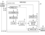
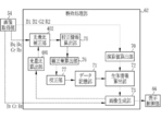
- the processor device 16 includes a control unit 52, an image acquisition unit 54, an image processing unit 61, and a display control unit 66.
- the control unit 52 receives the mode switching signal from the mode switching switch 13a and inputs the control signal to the light source control unit 22 and the image sensor 48 to switch the observation mode. In the special observation mode, the oxygen saturation observation mode and the calibration mode are switched. In addition, the control unit 52 also performs synchronous control of the illumination light irradiation timing and the photographing timing.
- the image acquisition unit 54 acquires an image to be observed from the image sensor 48.
- the image acquisition unit 54 acquires a Bc image, a Gc image, and an Rc image for each shooting frame.
- the image acquisition unit 54 uses a B1 image, G1 in a shooting frame that uses the second blue light BL as illumination light.
- the B2 image, the G2 image, and the R2 image are acquired in the photographing frame that acquires the image and the R1 image and uses white light as the illumination light.
- the image acquisition unit 54 acquires a Bp image, a Gp image, and an Rp image in a shooting frame that uses the first blue light BS as illumination light, and uses the second blue light BL as illumination light.
- a Bq image, a Gq image, and an Rq image are acquired in an imaging frame to be acquired
- a Br image, a Gr image, and an Rr image are acquired in an imaging frame that uses green light G as illumination light
- a red light R is emitted as illumination light.
- a Bs image, a Gs image, and an Rs image are acquired in the shooting frame used for the above.
- a Bt image, a Gt image, and an Rt image are acquired in an imaging frame inserted between them using white light as illumination light.
- the image acquisition unit 54 includes a DSP (Digital Signal Processor) 56, a noise reduction unit 58, and a conversion unit 59, and performs various processes on the acquired image using these.
- DSP Digital Signal Processor
- the DSP 56 performs various processing such as defect correction processing, offset processing, gain correction processing, linear matrix processing, gamma conversion processing, demosaic processing, and YC conversion processing on the acquired image as necessary.
- the defect correction process is a process for correcting the pixel value of the pixel corresponding to the defective pixel of the image sensor 48.
- the offset process is a process for reducing the dark current component from the image subjected to the defect correction process and setting an accurate zero level.
- the gain correction process is a process for adjusting the signal level of each image by multiplying the image subjected to the offset process by a gain.
- the linear matrix process is a process for improving the color reproducibility of the image subjected to the offset process, and the gamma conversion process is a process for adjusting the brightness and saturation of the image after the linear matrix process.
- the demosaic process (also referred to as an isotropic process or a synchronization process) is a process of interpolating the pixel values of the missing pixels, and is applied to the image after the gamma conversion process.
- the missing pixel is a pixel having no pixel value because pixels of other colors are arranged in the image sensor 48 due to the arrangement of the color filters.
- the B image is an image obtained by photographing the observation target in the B pixel, the pixel at the position corresponding to the G pixel or the R pixel of the image sensor 48 has no pixel value.
- the B image is interpolated to generate pixel values of the pixels at the positions of the G pixel and the R pixel of the image sensor 48.
- the YC conversion process is a process for converting the demosaiced image into a luminance channel Y, a color difference channel Cb, and a color difference channel Cr.
- the noise reduction unit 58 performs noise reduction processing on the luminance channel Y, the color difference channel Cb, and the color difference channel Cr using, for example, a moving average method or a median filter method.
- the conversion unit 59 reconverts the luminance channel Y, the color difference channel Cb, and the color difference channel Cr after the noise reduction processing into an image of each color of BGR again.
- the image processing unit 61 includes a normal processing unit 62 and a special processing unit 63.
- the normal processing unit 62 operates in the normal observation mode, and performs color conversion processing, color enhancement processing, and structure enhancement processing on the Bc image, Gc image, and Rc image for one shooting frame subjected to the above-described various processing. To generate a normal image.
- a 3 ⁇ 3 matrix process, a gradation conversion process, a three-dimensional LUT (look-up table) process, and the like are performed on an image of each color of BGR.
- the color enhancement process is a process for enhancing the color of an image
- the structure enhancement process is a process for enhancing a tissue or structure to be observed such as a blood vessel or a pit pattern.
- the display control unit 66 sequentially acquires normal images from the normal processing unit 62, converts the acquired normal images into a format suitable for display, and sequentially outputs and displays them on the monitor 18. Thereby, in the normal observation mode, the doctor or the like can observe the observation target using the moving image of the normal image.
- the special processing unit 63 includes a calculation value calculation unit 70, a data storage unit 71, a biological information calculation unit 72, an image generation unit 73, a calibration information calculation unit 75, a correction amount calculation unit 76, and a calibration unit. 77.
- the calculation value calculation unit 70, the biological information calculation unit 72, and the image generation unit 73 function in the oxygen saturation observation mode.
- the calculated value calculation unit 70 acquires the actual captured image obtained in the biological information observation mode from the image acquisition unit 54, and calculates the calculated value used by the biological information calculation unit 72 for calculating the biological information using the actual captured image. That is, since the biological information observation mode is the oxygen saturation observation mode and the oxygen saturation is calculated as biological information, the calculation value calculation unit 70 acquires the actual captured image obtained in the oxygen saturation observation mode from the image acquisition unit 54. Then, using the actual captured image, the biological information calculation unit 72 calculates a calculation value used for calculating the oxygen saturation. More specifically, the calculation value calculation unit 70 acquires the B1 image, the B2 image, the G2 image, and the R2 image from the image acquisition unit 54 in the oxygen saturation observation mode.
- the ratio B1 / G2 of the B1 image to the G2 image and the ratio R2 / G2 of the R2 image to the G2 image are calculated for each pixel.
- the ratio B1 / G2 and the ratio R2 / G2 are calculation values used for calculating the oxygen saturation.
- the data storage unit 71 stores data used when the biological information calculation unit 72 calculates the biological information using the calculated value calculated by the calculated value calculation unit 70. That is, since the oxygen saturation is calculated as the biological information, the data storage unit 71 stores the correlation between the calculation value calculated by the calculation value calculation unit 70 and the oxygen saturation in a format such as LUT. . As shown in FIG. 7, when this correlation is expressed in the first feature space formed by using the vertical axis Log (B1 / G2) and the horizontal axis Log (R2 / G2), the point where the oxygen saturation is the same value. An isoline connecting the lines is formed substantially along the horizontal direction. Further, the isoline is positioned downward in the vertical axis direction as the oxygen saturation is increased. For example, the isoline 83 with 100% oxygen saturation is located below the isoline 84 with 0% oxygen saturation.
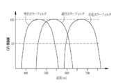
- the above correlation is closely related to the light absorption characteristics of oxygenated hemoglobin (graph 86) and reduced hemoglobin (graph 87) shown in FIG.
- the wavelength of the second blue light BL (about 470 ⁇ 10 nm) has a large difference in extinction coefficient between oxyhemoglobin and deoxyhemoglobin, so that the amount of light absorption changes due to the oxygen saturation of hemoglobin.
- the second blue light BL is easy to handle oxygen saturation information. Therefore, the oxygen saturation can be calculated by using the ratio B1 / G2 obtained by standardizing the B1 image by using the G2 image for correction of illuminance unevenness and the like.
- the ratio B1 / G2 depends not only on the oxygen saturation but also on the blood volume.
- the ratio R2 / G2 which changes mainly depending on the blood volume, is used, so that the oxygen saturation can be calculated without being influenced by the blood volume.
- the wavelength of the green light G (about 540 ⁇ 20 nm) included in the G2 image is a wavelength at which the extinction coefficient is likely to change due to the blood volume because the extinction coefficient of hemoglobin is relatively high.
- the data storage unit 71 stores a correlation between the ratio B1 / G2 and the ratio R2 / G2 and the oxygen saturation, but the data storage unit 71 may store other correlations. it can.
- the oxygen saturation using a calculated value (hereinafter referred to as another calculated value) obtained as a result of performing another calculation (for example, difference processing) different from the above based on the B1 image, the B2 image, the G2 image, and the R2 image.
- another calculated value obtained as a result of performing another calculation (for example, difference processing) different from the above based on the B1 image, the B2 image, the G2 image, and the R2 image.
- the data storage unit 71 can store a correlation that associates the other calculated values with the oxygen saturation.
- the biometric information calculation unit 72 refers to the data stored in the data storage unit 71 and calculates biometric information using the calculation value calculated by the calculation value calculation unit 70.
- the biological information calculation unit 72 functions as an oxygen saturation calculation unit.
- the biological information calculation unit 72 refers to the correlation stored in the data storage unit 71 and calculates the oxygen saturation corresponding to the ratio B1 / G2 and the ratio R2 / G2 for each pixel.
- the oxygen saturation corresponding to the ratio B1 * / G2 * and the ratio R2 * / G2 * of a specific pixel is “40%” with reference to the correlation stored in the data storage unit 71. Accordingly, the biological information calculation unit 72 calculates the oxygen saturation of the specific pixel as “40%”.
- the ratio B1 / G2 and the ratio R2 / G2 are hardly increased or extremely decreased. That is, the combinations of the values of the ratio B1 / G2 and the ratio R2 / G2 are distributed below the upper limit isoline 83 (see FIG. 7) of the oxygen saturation 100%, or conversely, the oxygen saturation 0 There is almost no distribution above the isoline 84 (see FIG. 7) at the lower limit of%. If the combination of each value of the ratio B1 / G2 and the ratio R2 / G2 is distributed below the upper limit isoline 83, the biological information calculation unit 72 calculates the oxygen saturation of the pixel as 100%. To do.
- the biological information calculation unit 72 sets the oxygen saturation of the pixel to 0%. And calculate. Further, when the points corresponding to the ratios B1 / G2 and R2 / G2 are not distributed between the upper limit isoline 83 and the lower limit isoline 84, the reliability of oxygen saturation in the pixel is low. May be displayed, or oxygen saturation may not be calculated.
- the image generation unit 73 In the biological information observation mode, the image generation unit 73 generates a biological information image representing the biological information calculated by the biological information calculation unit 72. That is, the image generation unit 73 generates an oxygen saturation image obtained by imaging the oxygen saturation using the oxygen saturation calculated by the biological information calculation unit 72. Specifically, the image generation unit 73 acquires a B2 image, a G2 image, and an R2 image, and applies a gain corresponding to the oxygen saturation to these images for each pixel. For example, the image generation unit 73 multiplies the B2 image, the G2 image, and the R2 image by the same gain “1” for pixels having oxygen saturation of 60% or more.
- a pixel having an oxygen saturation of less than 60% is multiplied by a gain less than “1” for the B2 image, and a gain of “1” or more is multiplied for the G2 image and the R2 image.
- the image generation unit 73 generates an oxygen saturation image that generates a color oxygen saturation image using the B2, G2, and R2 images that have been gained as described above.
- the oxygen saturation image generated by the image generation unit 73 is acquired by the display control unit 66 and sequentially displayed on the monitor 18.
- a region of high oxygen in this embodiment, a region where the oxygen saturation is 60% or more and 100% or less
- a low oxygen region in which the oxygen saturation is lower than a specific value in this embodiment, the oxygen saturation is 0% or more and less than 60%
- the image generation unit 73 multiplies the gain for pseudo-coloring only the low oxygen region, but the oxygen saturation is also increased in the high oxygen region.
- a corresponding gain may be applied to pseudo-color the entire oxygen saturation image.
- the low oxygen region and the high oxygen region are separated with an oxygen saturation of 60% as a boundary, but this boundary is also arbitrary.
- the calibration mode among the units of the special processing unit 63, the calibration information calculation unit 75, the correction amount calculation unit 76, the calibration unit 77, and the image generation unit 73 function.
- the calibration information calculation unit 75 acquires a pre-captured image from the image acquisition unit 54, and calculates biometric information (hereinafter referred to as calibration information) used for calibration in the biometric information observation mode using the pre-captured image.
- the calibration information is, for example, biological information unique to the observation target that represents the part or state of the observation target. Specifically, the calibration information calculation unit 75 first acquires at least a Bp image, a Bq image, a Gr image, and an Rs image from the image acquisition unit 54. And biological information related to yellow pigment (such as bilirubin and stercobilin) attached to the observation object and low dependency on oxygen saturation, and other biological information used for calibration of the oxygen saturation observation mode, Is calculated.
- the term “related to yellow pigment” means that there is a correlation in the amount or concentration of yellow pigment deposited. Further, the low dependency on the oxygen saturation means that the value of the yellow pigment information does not substantially change due to the value of the oxygen saturation.
- the calibration information calculation unit 75 firstly calculates the ratio Bp / Gr of the Bp image to the Gr image, the ratio Bq / Gr of the Bq image to the Gr image, and the ratio Rs / Gr of the Rs image to the Gr image. Are calculated for each pixel.
- the Bp image is an image corresponding to the first blue light BS, and the wavelength band of the first blue light BS (center wavelength about 450 ⁇ 10 nm) has a relatively high extinction coefficient of hemoglobin, and oxygenated hemoglobin and reduced hemoglobin. It is an isosbestic wavelength having substantially the same extinction coefficient (see FIG. 8). For this reason, the Bp image is an image whose value hardly changes due to oxygen saturation. Further, as shown in FIG. 9, the first blue light BS has a wavelength band in which the absorption coefficient of the yellow dye is substantially the highest, and therefore the amount of absorption changes according to the amount or concentration of the yellow dye. Cheap.
- the value of the ratio Bp / Gr obtained by standardizing the Bp image using the Gr image for correction of illuminance unevenness and the like hardly changes due to the oxygen saturation, but the amount of yellow dye attached Or it changes due to concentration.
- the wavelength band of the green light G corresponding to the Gr image is a wavelength band in which the amount of light absorption easily changes due to the blood volume, and thus the ratio Bp / Gr changes due to the blood volume.
- the Bq image is an image corresponding to the second blue light BL, and the wavelength band (about 470 ⁇ 10 nm) of the second blue light BL has a relatively high hemoglobin extinction coefficient, and the oxygenated hemoglobin and the reduced hemoglobin. Wavelength bands with different extinction coefficients (see FIG. 8). For this reason, the Bq image is an image that easily changes due to the oxygen saturation. Moreover, although the wavelength band of the second blue light BL is slightly deviated from the absorption peak of the yellow pigment, it has a large extinction coefficient compared to other wavelength bands (see FIG. 9). From these facts, the value of the ratio Bq / Gr obtained by standardizing the Bq image using the Gr image for correction of illuminance unevenness, etc. is attributed to the oxygen saturation and the adhesion amount or concentration of the yellow pigment. The value changes. Further, since the Gr image is dependent on the blood volume, the value of the ratio Bq / Gr changes due to the blood volume.
- the Rs image is an image corresponding to the red light R, and the wavelength band of the red light R (center wavelength of about 640 ⁇ 20 nm) is compared to the wavelength bands of the first blue light BS and the second blue light BL.
- the extinction coefficient of hemoglobin is very small (see FIG. 8). For this reason, although there is a difference in the extinction coefficient between oxyhemoglobin and deoxyhemoglobin, the Rs image is substantially independent of oxygen saturation because the amount of light absorption is too small.
- the yellow dye since the extinction coefficient of the yellow dye in the wavelength band of the red light R is very small compared to the wavelength bands of the first blue light BS and the second blue light BL, the Rs image is the yellow dye.
- the value of the ratio Rs / Gr obtained by standardizing the Rs image using the Gr image for correction of illuminance unevenness and the like hardly depends on the oxygen saturation, the yellow pigment adhesion amount, or the concentration.
- the ratio Rs / Gr changes due to the blood volume, reflecting the blood volume dependency of the Gr image.
- the calibration information calculation unit 75 is more accurately related to the yellow pigment attached to the observation target and is less dependent on oxygen saturation (hereinafter referred to as yellow pigment information).
- Vy is calculated based on the following formula A.
- the phase ⁇ is a known amount that is adjusted in advance so that the yellow pigment information Vy obtained by the calculation based on the equation A becomes constant even when the oxygen saturation changes.
- the calibration information calculation unit 75 inputs the yellow pigment information Vy after the adjustment of the phase ⁇ and the ratio Rs / Gr to the correction amount calculation unit 76 as calibration information.
- Vy (Bp / Gr) ⁇ cos ⁇ + (Bq / Gr) ⁇ sin ⁇
- the correction amount calculation unit 76 calculates a correction amount of data used for calculation of biological information from predetermined reference information and the calibration information calculated by the calibration information calculation unit 75. That is, the correction amount calculation unit 76 uses the yellow pigment information Vy to calculate the correlation correction amount ⁇ D used for calculating the oxygen saturation. Further, by using the calibration information calculated by the calibration information calculation unit 75, the correction amount calculation unit 76 substantially uses the calibration image for calculating the correction amount.
- the reference information is a correlation between the yellow pigment information Vy and the ratio Rs / Gr acquired in a state where there is almost no yellow pigment.
- the yellow pigment information Vy constituting the reference information is obtained by using the Bp image, the Bq image, and the Gr image acquired in a state where there is almost no yellow pigment, so that there is no change due to the oxygen saturation. Is the yellow pigment information Vy calculated according to the formula A. In this process, the phase ⁇ of equation A is also determined.
- the reference information can be determined in advance by, for example, photographing or simulating a phantom imitating a living body.
- the data used for calculating the biological information in the biological information observation mode is a correlation stored in the data storage unit 71 in the present embodiment.
- the correction amount calculation unit 76 calculates the correction amount ⁇ D using the second feature space in which the vertical axis represents yellow pigment information Vy and the horizontal axis represents Log (Rs / Gr). Since the ratio Rs / Gr used on the horizontal axis represents the blood volume, the second feature space represents the distribution of yellow pigment information Vy relative to the blood volume, and the line connecting the points where the yellow pigment information Vy is equal in the second feature space is yellow. It is an isoline (hereinafter referred to as an isoconcentration line) having the same pigment concentration (or adhesion amount).
- the reference information forms a reference isoconcentration line 94 in the second feature space. For this reason, if there is actually no yellow pigment, the point where the yellow pigment information Vy and the ratio Rs / Gr obtained by actually pre-photographing the observation object are set in the second feature space is on the reference isodensity line 94. However, if there is a yellow pigment, it will fall on another isoconcentration line 96 at a position deviated from the reference isoconcentration line 94 due to the amount or density of the yellow pigment.
- the coefficient ⁇ is a value for scaling the difference ⁇ Z to a value suitable for correcting the correlation stored in the data storage unit 71. Since the value of the yellow pigment information Vy increases as the adhesion amount or density of the yellow pigment decreases, the isodensity line of the second feature space is formed below the reference isodensity line 94.
- the calibrating unit 77 calibrates the biological information observation mode by correcting the data used for the calculation of the biological information using the correction amount ⁇ D calculated by the correction amount calculating unit 76.
- the calibration unit 77 calibrates the oxygen saturation observation mode by correcting the correlation stored in the data storage unit 71 using the correction amount ⁇ D.
- the calibration unit 77 adds the correction amount ⁇ D to the value of Log (B1 / G2) on the vertical axis to all isolines in the first feature space (see FIG. 7). That is, the calibration unit 77 shifts all isolines in the first feature space upward in the vertical axis by the correction amount ⁇ D.
- the biological information calculation unit 72 can calculate an accurate oxygen saturation that does not depend on an error factor specific to the observation target.
- the biological information observation mode (oxygen saturation observation mode) is calibrated using the calibration information calculation unit 75, the correction amount calculation unit 76, and the calibration unit 77, while the image generation unit 73 is in the calibration mode.
- the Bt image, the Gt image, and the Rt image (that is, an image obtained using white light during the calibration mode) are sequentially acquired from the image acquisition unit 54.
- the image generation unit 73 performs a color conversion process, a color enhancement process, and a structure enhancement process on the Bt image, the Gt image, and the Rt image for one shooting frame to generate a white light image 202.
- the white light image 202 is the same as the normal image in the normal observation mode except that it is generated during the calibration mode. Therefore, by using the white light image 202, it is possible to observe an observation object with a natural hue.
- the display control unit 66 sequentially acquires the white light images 202 generated by the image generation unit 73 and displays them on the monitor 18 in the calibration mode. For this reason, even when the pre-photographed image is being captured in the calibration mode, the observation of the observation target can be continued without interruption using the white light image 202 or the moving image composed of the white light image 202.
- the control unit 52 inputs control signals to the light source control unit 22 and the image sensor 48.
- the calibration mode is executed (S11).
- the oxygen saturation observation mode biological information observation mode
- the observation object is photographed using white light while the pre-photographed image is obtained, and the white light image 202 is displayed on the monitor 18.
- the doctor or the like looks at the white light image 202 (or the moving image composed of the white light image 202) and determines whether or not the oxygen saturation observation mode has been correctly calibrated (S12). Specifically, since oxygen saturation cannot be accurately calibrated if pre-photographing is performed under inappropriate conditions, the pre-photographing is appropriate by looking at the white light image 202 displayed on the monitor 18 during the calibration mode. Confirm that it was done. For example, conditions related to the shooting position, such as whether there is an obvious lesion in the observation target, whether the brightness is appropriate, and whether the observation target is blurred due to the movement of the observation target. Judgment is made from the white light image 202 obtained almost simultaneously with the pre-photographed image.
- the calibration mode is executed again.
- the process proceeds to the oxygen saturation observation mode, which is the biological information observation mode of the present embodiment (S13).
- the endoscope system 10 calculates the oxygen saturation using the actual captured image obtained by performing the actual imaging, and shows the value of the oxygen saturation using a pseudo color.
- the light source unit 20 emits the first blue light BS (S21), and the image sensor 48 uses the first blue light BS.
- the observation object is automatically pre-photographed, and the image acquisition unit 54 acquires a Bp image used for calibration in the oxygen saturation observation mode (S22).
- the light source unit 20 emits white light (S23).
- the image sensor 48 automatically images the observation target using white light, and the image acquisition unit 54 acquires the Bt image, the Gt image, and the Rt image. (S24).
- the image generation unit 73 generates the white light image 202 using the Bt image, Gt image, and Rt image obtained here, and the display control unit 66 displays the white light image 202 on the monitor 18. Displayed (S25).
- the light source unit 20 emits the second blue light BL (S26). Then, the image sensor 48 automatically captures an observation target using the second blue light BL, and the image acquisition unit 54 acquires a Bq image necessary for calibration in the oxygen saturation observation mode (S27). In the next photographing frame from which the Bq image is obtained, the light source unit 20 emits white light again instead of emitting the illumination light for obtaining the next pre-photographed image (S28). Therefore, the image sensor 48 automatically captures the observation target using white light, and the image acquisition unit 54 acquires the Bt image, the Gt image, and the Rt image again (S29). The image generation unit 73 generates a white light image 202 from these Bt image, Gt image, and Rt image, and the display control unit 66 displays the generated white light image 202 on the monitor 18 (S30).
- the light source unit 20 emits green light G (S31). Then, the image sensor 48 automatically captures an observation target using the green light G, and the image acquisition unit 54 acquires a Gr image necessary for calibration in the oxygen saturation observation mode (S32). Next, the light source unit 20 emits white light again (S33), the image sensor 48 automatically captures the observation target using the white light, and the image acquisition unit 54 performs Bt image, Gt image, and Rt image. Is acquired (S34). For this reason, the image generation unit 73 generates a white light image 202 using these, and the display control unit 66 displays the white light image 202 on the monitor 18 (S35).
- the light source unit 20 emits red light R (S36)
- the image sensor 48 automatically photographs the observation target using the red light R
- the image acquisition unit 54 is saturated with oxygen.
- An Rs image which is the last image necessary for calibration in the degree observation mode, is acquired (S37).
- a plurality of pre-photographed images that is, Bp images, Bq images, Gr images, and Rs images
- the calibration information calculation unit 75 uses the pre-photographed images to calculate biometric information unique to the observation target representing the region and state of the observation target as calibration information (S38).
- the correction amount calculation unit 76 corrects the correlation used for the calculation of the oxygen saturation using the calibration information calculated by the calibration information calculation unit 75, whereby oxygen saturation.
- the degree observation mode is calibrated (S40).
- the light source unit 20 first emits the second blue light BL (S51). Then, the image sensor 48 automatically captures an observation target using the second blue light BL, and the image acquisition unit 54 acquires a B1 image essential for calculating the oxygen saturation (S52). Thereafter, in the next imaging frame, the light source unit 20 emits white light (S53), and the image sensor 48 automatically captures an observation target using the white light, so that the image acquisition unit 54 B2 image, G2 image, and R2 image necessary for calculation of saturation and generation of oxygen saturation image are acquired (S54).
- the calculated value calculation unit 70 calculates a calculated value necessary for calculating the oxygen saturation (S55). Specifically, the calculated value calculation unit 70 calculates the ratio B1 / G2 and the ratio R2 / G2 for each pixel.
- the biological information calculation unit 72 refers to the correlation in the data storage unit 71 and calculates the oxygen saturation of the observation target for each pixel from the ratio B1 / G2 and the ratio R2 / G2 calculated by the calculation value calculation unit 70. (S56).
- the biological information calculation unit 72 uses the correlation corrected by the calibration unit 77 in the calibration mode, not the default correlation stored in advance in the data storage unit 71. For this reason, the oxygen saturation calculated by the biological information calculation unit 72 is accurate because it is not affected by an error factor specific to the observation target.
- the image generation unit 73 applies a gain corresponding to the oxygen saturation to the B2 image, the G2 image, and the R2 image, and converts the value of the oxygen saturation into a pseudo color.
- the oxygen saturation image expressed using is generated, and the display control unit 66 displays the oxygen saturation image on the monitor 18 (S57).
- the endoscope system 10 has a biological information observation mode and a calibration mode for calibrating the biological information observation mode.
- the endoscope system 10 simply obtains a pre-captured image,
- the white light image 202 is generated and displayed during (or before and after) obtaining the pre-photographed image. For this reason, doctors and the like can continuously observe the observation target even in the calibration mode.
- the white light image 202 displayed on the monitor 18 during the calibration mode is acquired almost simultaneously with the pre-photographed image, it represents the state of the observation target before or after obtaining the pre-photographed image. For this reason, doctors or the like determine whether or not pre-imaging has been properly performed by displaying the white light image 202 in the calibration mode, that is, whether or not the oxygen saturation observation mode, which is the biological information observation mode, has been accurately calibrated. Opportunity to make a decision.
- the oxygen saturation observation mode biological information observation mode
- the calibration mode is executed again, so that the oxygen saturation observation mode can be calibrated reliably and accurately. Therefore, in the endoscope system 10, when there is no change in the observation target (for example, secretion of mucus etc.) that requires calibration again, the oxygen saturation can be ensured at the time of transition to the oxygen saturation observation mode. And it can be calculated accurately.
- the correction amount calculation unit 76 calculates the correction amount ⁇ D using the second feature space.
- the correction amount ⁇ D is calculated based on the Bp image, the Bq image, the Gr image, and the Rs. It is also possible to calculate by performing a conversion process combining matrix processing and 1D-LUT (1 (Dimensional Look Up Table) on the image.
- the oxygen saturation observation mode is calibrated with respect to the adhesion amount or concentration of the yellow pigment, but the oxygen saturation observation mode can be calibrated with respect to a state unique to another observation target.
- the calibration information calculation unit 75 may calculate, as calibration information, biological information related to a state unique to the observation target to be calibrated instead of biological information related to the adhesion amount or concentration of the yellow pigment.
- the operations of the correction amount calculation unit 76 and the calibration unit 77 are the same as those in the first embodiment.
- the white light image 202 is obtained (see FIG. 4), but any one of the timings of emitting the white light can be omitted. Further, the white light may be emitted before emitting the first blue light BS to obtain the white light image 202, or the white light may be emitted after the red light R is emitted to obtain the white light image 202. good. That is, it is only necessary that the white light image 202 can be generated and displayed by emitting white light at least once during the calibration mode.
- the pre-captured image is acquired in the order of the Bp image, the Bq image, the Gr image, and the Rs image (see FIG. 12).
- the acquisition order of is arbitrary.
- pre-photographed images can be acquired in the order of Rs image, Bq image, Bp image, and Gr image.
- the calibration accuracy in the oxygen saturation observation mode is particularly likely to be lowered. For this reason, it is preferable to acquire a Bp image and a Bq image continuously as much as possible.
- the emission intervals of the two calibration illumination lights of the combination that has the largest contribution to the calculation accuracy of the correction amount ⁇ D used for the calibration in the oxygen saturation observation mode are set as the other calibration illumination lights. It is preferable to make it shorter than the light emission interval.
- the Bp image and the Bq image are continuously acquired with respect to the acquisition order of the pre-photographed images, and a photographing frame for generating and displaying the white light image 202 is inserted between the Bq image and the Bq image. I do not care.
- the entire pre-captured image is used to calibrate the biological information observation mode (oxygen saturation observation mode).
- the biological information observation mode oxygen saturation observation mode
- the special processing unit 63 is provided with the region setting unit 201 that operates in the calibration mode, as shown in FIG.
- the region setting unit 201 acquires a pre-captured image (that is, a Bp image, a Bq image, a Gr image, and an Rs image) used for calibration of the oxygen saturation observation mode that is the biological information observation mode from the image acquisition unit 54, A part of these pre-photographed images is set in an area (hereinafter referred to as “use area”) 203 (see FIG. 15) used for calibration in the oxygen saturation observation mode.
- use area an area
- the calibration information calculation unit 75 calculates the calibration information only for the use region 203 set by the region setting unit 201.
- the correction amount calculation unit 76 also calculates the correction amount ⁇ D for the use region.
- the correction of the correlation performed by the calibration unit 77 (that is, calibration of the oxygen saturation observation mode) is performed on the entire pre-captured image. Instead, only the use area 203 that is part of the pre-captured image is used. In this way, if the use area 203 is set in a part of the pre-photographed image and the oxygen saturation observation mode is calibrated using only the use area 203 instead of the entire pre-photographed image, the error factor of the calibration can be reduced. Therefore, the oxygen saturation observation mode can be calibrated more accurately.
- the area setting unit 201 has a portion that is too bright (a portion causing halation), a portion that is too dark (portion that has been crushed black due to insufficient light amount), residue, or residual liquid from a pre-photographed image. A portion that causes a calibration error such as a portion being detected is detected, and a region excluding these is set as a use region 203.
- the area setting unit 201 can detect a normal part that can be said to have no lesion or the like based on the shape or the like of the observation target, and can set the detected normal part as the use area 203.
- the area setting unit 201 can set an area excluding a peripheral area of an image in which illuminance unevenness is likely to occur and a certain range of a part at the back of the observation target as the use area 203.
- the use area 203 can be manually set by an operation input from the console 19 or the like.
- the image generation unit 73 Information on the position and range of the use area 203 set by the area setting unit 201 (hereinafter referred to as position information) is acquired from the setting unit 201.
- position information information on the position and range of the use area 203 set by the area setting unit 201
- the display control unit 66 displays the white light image 202 on the monitor 18, the display area 66 sets the use region 203 set by the region setting unit 201 to the white light image 202 based on the position information.
- superimposed display is illustrated in FIG. 15
- the doctor or the like uses the white light image 202 to check whether the state of use can be an error factor such as the movement of the observation target, and also checks whether the use area 203 is not appropriate. If the set use area 203 is inappropriate, the oxygen saturation can be calibrated again.
- the area setting unit 201 detects and sets the use area 203 using the pre-captured image. Instead, the area setting unit 201 uses the white light image 202. An area 203 can be set.
- the use area 203 is superimposed on the white light image 202, but the numerical value of the correction amount ⁇ D and the indicator indicating the numerical value of the correction amount ⁇ D are also superimposed on the white light image 202. Also good. This is because a specific numerical value or the like of the correction amount ⁇ D also serves as a material for determining whether or not the oxygen saturation observation mode is correctly calibrated. For example, when the correction amount ⁇ D is extremely large, there is a possibility that the state of the observation target is far from the normal state, for example, the lesion is spread over the entire captured part. Such abnormalities can be detected by looking at specific numerical values of the correction amount ⁇ D.
- the superimposed display of the numerical value of the correction amount ⁇ D is also effective in the case of the first embodiment.
- the light source unit 20 inserts white light emission a plurality of times while sequentially emitting calibration illumination light for obtaining a pre-photographed image in the calibration mode.
- the monitor 18 generates and displays the white light image 202 from the image obtained in each photographing frame that emits white light.
- the special processing unit 63 further includes a motion amount calculation unit 301 and a position deviation correction unit 302 that operate in the calibration mode.
- the motion amount calculation unit 301 sequentially acquires the white light images 202 generated by the image generation unit 73, and calculates the motion amount of the observation target from the plurality of acquired white light images 202. Specifically, the motion amount calculation unit 301 detects a plurality of vectors (hereinafter referred to as motion vectors) representing the motion of the observation target between the white light images 202 by matching the two white light images 202 acquired sequentially. To do. Then, from these motion vectors, the direction and magnitude of movement, rotation, deformation, etc. of the observation object are calculated. The direction and magnitude of the movement, rotation, deformation, etc. of the observation object calculated in this way is the amount of movement.
- motion vectors a plurality of vectors representing the motion of the observation target between the white light images 202 by matching the two white light images 202 acquired sequentially. To do. Then, from these motion vectors, the direction and magnitude of movement, rotation, deformation, etc. of the observation object are calculated. The direction and magnitude of the movement, rotation, deformation, etc
- the positional deviation correction unit 302 corrects the positional deviation of the observation target of the calibration image using the motion amount calculated by the motion amount calculation unit 301. That is, the positional deviation correction unit 302 corrects the positional deviation of the observation target of the Bp image, the Bq image, the Gr image, and the Rs image that are calibration images.
- the white light image 202 obtained first in the calibration mode white light image 202 obtained in step S25 in FIG. 12
- the white light image 202 obtained next white light image 202 obtained in step S30 in FIG. 12
- the amount of motion is approximately equal to the amount of motion of the observation target between the Bp image, the Bq image, and the Gr image acquired before and after the first white light image 202 obtained and the second white light image 202 obtained next.
- the second white light image 202 obtained in the calibration mode (white light image 202 obtained in step S30 of FIG. 12) and the third white light image 202 obtained (white light image 202 obtained in step S35 of FIG. 12).
- the amount of motion is approximately equal to the amount of motion of the observation target between the Bq image, the Gr image, and the Rs image acquired before and after these. Therefore, if these movement amounts are used, even if there is some movement in the observation target of the Bp image, Bq image, Gr image, and Rs image, the positional deviation of the observation target between these images can be corrected.
- the calibration information calculation unit 75 calculates calibration information using the Bp image, the Bq image, the Gr image, and the Rs image obtained by correcting the positional deviation of the observation target using the positional deviation correction unit 302 as described above. For this reason, the calibration information can be calculated more accurately than in the case where the positional deviation of the observation target is not corrected. Therefore, in the present embodiment, errors due to the movement of the observation target can be reduced, so that the oxygen saturation observation mode is more accurately calibrated.
- the motion amount calculation unit 301 calculates the motion amount using the white light image 202 generated by the image generation unit 73, but the motion amount calculation unit 301 Instead, the amount of motion can be calculated using an image for generating the white light image 202. Specifically, since the image generation unit 73 generates the white light image 202 using the Bt image, the Gt image, and the Rt image, the motion amount calculation unit 301 can select any of the Bt image, the Gt image, and the Rt image. Or all of them can be used to calculate the amount of motion.
- the amount of motion is calculated from the plurality of white light images 202 to correct the positional deviation of the observation target of the calibration image. Instead, the plurality of white light images are corrected.
- the light amount ratio of 202 may be calculated, and the light amount ratio of the calibration image may be corrected using the calculated light amount ratio.
- the special processing unit 63 is provided with a light amount ratio calculation unit 401 and a light amount ratio correction unit 402 that function in the calibration mode.
- the light amount ratio calculation unit 401 sequentially acquires the white light images 202 from the image generation unit 73 and calculates their light amount ratio.
- the light amount of the image is, for example, an average value of luminance of all or some of the pixels (hereinafter referred to as average luminance), and the light amount ratio of the image is a ratio of the average luminance of the contrasted images. Therefore, the light quantity ratio of the plurality of white light images 202 is the ratio of the average luminance of each white light image 202.
- the light amount ratio correcting unit 402 corrects the light amount ratio of the calibration image using the light amount ratio calculated by the light amount ratio calculating unit 401.
- the light quantity ratio calculation unit 401 first obtains the white light image 202 (white light image 202 obtained in step S25 in FIG. 12) and the white light image 202 obtained next (white color obtained in step S30 in FIG. 12) in the calibration mode.
- this light quantity ratio generally represents a change in the light quantity of the Bp image, the Bq image, and the Gr image acquired before and after the white light image 202.
- the light quantity ratio calculation unit 401 obtains the second white light image 202 (white light image 202 obtained in step S30 in FIG.
- the light quantity ratio correction unit 402 can correct the light quantity ratios of the Bp image, the Bq image, the Gr image, and the Rs image.
- the calibration information calculation unit 75 calculates calibration information using the Bp image, Bq image, Gr image, and Rs image in which the light amount ratio is corrected using the light amount ratio correction unit 402 as described above. For this reason, the illumination light is emitted from the first blue light BS, the second blue light BL, the green light G, and the red light R due to a variation in the light emission amount, etc. Even in the case where there is a change in the light amount of the Rs image, in this embodiment, the light amount ratio of each of these calibration images is corrected, so that the calibration information can be accurately calculated. Therefore, in the present embodiment, the error due to the change in the light amount of the calibration image can be reduced, so that the calibration in the oxygen saturation observation mode becomes more accurate.
- the light amount ratio calculating unit 401 calculates the light amount ratio using the white light image 202 generated by the image generating unit 73.
- the light amount ratio calculating unit 401 is a white light image.
- the light amount ratio can be calculated using an image for generating the white light image 202.
- the image generation unit 73 since the image generation unit 73 generates the white light image 202 using the Bt image, the Gt image, and the Rt image, the light amount ratio calculation unit 401 can select any of the Bt image, the Gt image, or the Rt image. Or all of them can be used to calculate the light quantity ratio.
- the fourth embodiment can be combined with the third embodiment. That is, both the amount of movement and the light amount ratio are calculated from the plurality of white light images 202 obtained in the calibration mode, and the positional deviation of the observation target of the calibration image is corrected using these, and the light amount of the calibration image is corrected.
- the ratio can be corrected.
- the special amount processing unit 63 may include the motion amount calculation unit 301 and the positional deviation correction unit 302 of the third embodiment and the light amount ratio calculation unit 401 and the light amount ratio correction unit 402 of the fourth embodiment.
- a set of calibration images (a set of Bp images, Bq images, Gr images, and Rs images) is acquired to calibrate the oxygen saturation observation mode.
- a plurality of sets of calibration images may be obtained. For example, as shown in FIG. 18, the first blue light BS, white light, second blue light BL, green light G, and red light R are emitted as one set as in the first embodiment. 1 set to 5th set can be executed together.
- the image obtained when each light is emitted is the same as that of the first embodiment, in the above case, if it is limited to the calibration image, the Bp image, the Bq image, the Gr image, and the Rs image are set as one set, and 5 sets worth are obtained. A calibration image is obtained.
- correction amount calculation unit 76 uses at least the calibration information calculated by using the first set of calibration images, so that the first set of calibration images is used.
- a first set of correction amounts resulting from the image hereinafter referred to as correction amount ⁇ D1 for distinction; the same applies to other sets).
- correction amount ⁇ D1 A first set of correction amounts resulting from the image
- the second set correction amount ⁇ D2 the third set correction amount ⁇ D3, the fourth set correction amount ⁇ D4, and the fifth set correction amount ⁇ D5 can be calculated.
- the oxygen saturation observation mode can be calibrated more accurately by obtaining a plurality of sets of calibration images in the calibration mode.
- the correction amounts ⁇ D1 to ⁇ D5 are calculated for each set, but the correction amount can also be calculated by using a combination of calibration images obtained in different sets.
- the correction amount ⁇ D can be calculated using the Bq image, the Gr image, and the Rs image obtained in the first set and the Bp image obtained in the second set.
- the correction amount can be calculated using the Gr image and Rs image obtained in the first set and the Bp image and Bq image obtained in the second set.
- twelve correction amounts ⁇ D can be calculated in total by changing the calibration image to be used for every two shooting frames.
- the correction amount ⁇ D calculated by combining the calibration images obtained in different sets is added and the five or more correction amounts ⁇ D are averaged, the correction amount ⁇ D is a more accurate value than the fifth embodiment. become. Therefore, as a result, the oxygen saturation observation mode can be calibrated more accurately.
- the fifth embodiment and the modification after calculating a plurality of correction amounts ⁇ D in the calibration mode, these are averaged. Instead of averaging, the median value of the plurality of correction amounts ⁇ D is calibrated. The correction amount ⁇ D used by the unit 77 may be used.
- the motion amount calculation unit 511 when acquiring a plurality of sets of calibration images and calculating a plurality of correction amounts ⁇ in the calibration mode, as shown in FIG. It is preferable to provide a motion amount calculation unit 511. Similar to the motion amount calculation unit 301 of the third embodiment, the motion amount calculation unit 511 sequentially acquires the white light images 202 from the image generation unit 73, and the motion of the observation target between the acquired white light images 202. Calculate the amount. However, the motion amount calculation unit 511 inputs the calculated motion amount to the correction amount calculation unit 76.
- correction amount calculation unit 76 as described in the fifth embodiment, a plurality of correction amounts ⁇ D are calculated, and a value obtained by weighting and averaging the calculated plurality of correction amounts ⁇ D using a motion amount is calibrated.
- the correction amount ⁇ D used in the section 77 is assumed. For example, if five correction amounts ⁇ D1 to ⁇ D5 are calculated for each set, and each movement amount from the first set to the fifth set (or the average value of the movement amount of each set) is ⁇ 1 to ⁇ 5, correction is performed.
- the amount calculation unit 76 multiplies these movement amounts ⁇ 1 to ⁇ 5 by the correction amounts ⁇ D1 to ⁇ D5 of each set and averages them, and calculates a correction amount ⁇ D used in the calibration unit 77.
- the calibration unit 77 corrects the correlation using the weighted average value using the amount of motion, the oxygen saturation observation mode can be calibrated more accurately than in the fifth embodiment.
- the correction amount calculation unit 76 uses the amount of motion as described above, and instead of averaging the plurality of correction amounts ⁇ D, the amount of correction is used to calculate oxygen saturation from the plurality of correction amounts ⁇ D. It is also possible to select a correction amount ⁇ D that is optimal for the calibration of the degree observation mode.
- the correction amount calculation unit 76 changes the third set of correction amounts ⁇ D3 to the correction amount ⁇ D used by the calibration unit 77. select.
- the correction amount ⁇ D of the set with the smallest amount of motion or the correction amount ⁇ D calculated using the calibration image of the combination with the smallest amount of motion is selected and used to correct the oxygen saturation observation mode. By doing so, it is possible to calibrate the oxygen saturation observation mode more easily than the weighted average and more accurately than the fifth embodiment.
- a light amount ratio calculation unit 521 that calculates the light amount ratio of the plurality of white light images 202 may be provided as in the fourth embodiment.
- the light quantity ratio calculation unit 521 calculates a plurality of light quantity ratios, for example, for each set.
- the light amount ratio calculated by the light amount ratio calculation unit 521 can be used instead of the motion amount calculated by the motion amount calculation unit 511. That is, using the light amount ratio calculated by the light amount ratio calculation unit 521, the correction amount ⁇ D used in the calibration unit 77 can be calculated by weighting and averaging the plurality of correction amounts ⁇ D.
- a correction amount ⁇ D that is optimal for calibration in the oxygen saturation observation mode (for example, correction of a set that minimizes the light amount ratio).
- the quantity ⁇ D) can be selected.
- the number of sets of calibration images to be acquired during the calibration mode is determined.
- the time for executing the calibration mode may be determined.
- the calibration mode duration may be set to 5 seconds or the like, and as many calibration images as possible may be acquired within this time including the time to acquire the white light image 202.
- the calibration mode when the observation mode is switched to the special observation mode, the calibration mode is automatically executed. However, the calibration mode is not automatically executed and the special observation mode is switched. At this time, the oxygen saturation observation mode may be automatically executed, and the calibration mode may be arbitrarily executed during the oxygen saturation observation mode.
- the processor device 16 sequentially acquires the oxygen saturation image and calculates the motion amount, and the calibration mode using the motion amount calculated by the motion amount calculation unit 611. It is good to provide the determination part 612 which determines whether to perform.
- the determination unit 612 determines, for example, that the calibration mode is to be executed when the amount of movement is equal to or less than the threshold and the movement of the observation target is small, and inputs a control signal to that effect to the control unit 52, whereby the oxygen saturation level is determined. Automatically insert calibration mode during observation mode. In this way, by determining the optimal situation for the calibration of the oxygen saturation observation mode using the amount of movement, and executing the calibration mode when the optimal situation for the calibration of the calibration mode is reached, the oxygen saturation observation mode Proofreading is easy to succeed.
- the motion amount calculation unit 611 calculates the motion amount from the oxygen saturation image, but instead of the oxygen saturation image, images for generating the oxygen saturation image (B1, B2, G2, and The amount of motion can be calculated using (R2 image). If the determination unit 612 determines to execute the calibration mode, the calibration mode is automatically inserted into the oxygen saturation observation mode by inputting a control signal to the control unit 52. The situation suitable for the mode may be notified using a display (message or the like) on the monitor 18 or the like to prompt manual switching to the calibration mode. Further, the motion amount calculation unit 611 and the determination unit 612 may be provided in the special processing unit 63.
- the special processing unit 63 is provided with a mucosa determination unit 621 for determining the state of the mucous membrane
- the calibration mode is inserted in the oxygen saturation observation mode according to the determination result of the mucosa determination unit 621.
- the mucous membrane determination unit 621 acquires, for example, a B1 image, a B2 image, a G2 image, or an R2 image from the image acquisition unit 54, and detects the state of the mucosa to be observed using any or all of these.
- the calibration mode can be automatically inserted during the oxygen saturation observation mode.
- the mucosa determination unit 621 may determine the color of the mucous membrane. For example, when there is no discoloration (eg, redness) suspected of being a lesion, or when it is determined that the color of the mucosa has changed due to the endoscope 12 entering the stomach from the esophagus and the observation target has become a different organ.
- the mucous membrane determination unit 621 can input a control signal that prompts execution of the calibration mode to the control unit 52, and can automatically insert the calibration mode during the oxygen saturation observation mode.
- the mucous membrane determination unit 621 instead of automatically inserting the calibration mode, the situation suitable for the calibration mode is notified using a display (message or the like) on the monitor 18 or the like, and the calibration mode is entered. The manual switching may be prompted.
- the first blue light BS, the second blue light BL, the green light G, and the red light R are individually emitted to obtain a calibration image.
- a part of the light can be emitted at the same time, and a part of the calibration image can be acquired simultaneously.
- green light G and red light R can be emitted simultaneously, and a Gr image and an Rs image can be acquired simultaneously.
- the first blue light BS, the green light G, and the red light R are simultaneously emitted, the Bp image, the Gr image, and the Rs image are simultaneously obtained, and the second blue light BL is emitted alone.
- the Bq image can be acquired separately.
- the first blue light BS is emitted alone to acquire a Bp image
- the second blue light BL, green light G, and red light R are simultaneously emitted to simultaneously acquire a Bq image, a Gr image, and an Rs image.
- Can do That is, if the first blue light BS and the second blue light BL received by the B pixel are emitted in different shooting frames, and the Bp image and the Bq image are obtained separately, the other calibration images can be obtained simultaneously. it can.
- the oxygen saturation observation mode is basically calibrated in one calibration mode.
- the calibration mode is performed a plurality of times manually or automatically, the calibration performed previously is performed. Calibration can be performed over the calibration result in the mode. That is, when the calibration mode is executed a plurality of times, the default correlation stored in advance in the data storage unit 71 is not always corrected, but the correlation corrected in the previous calibration mode can be corrected. In this way, even if the calibration accuracy in one calibration mode is somewhat low, the calibration accuracy can be improved step by step.
- the biological information observation mode is the oxygen saturation observation mode.
- the present invention is also applicable to a biological information observation mode that calculates biological information other than oxygen saturation. .
- a plurality of calibration illumination lights having different colors (wavelengths) are used in the calibration mode, but the observation target is photographed a plurality of times using the same color calibration illumination lights.
- the biological information observation mode can be calibrated using a plurality of pre-photographed images obtained in this manner.
- the light source unit 20 includes a plurality of light sources 20a to 20d, and the light emitted from these light sources is superimposed to form illumination light. Can form illumination light by extracting and using some components from the light emitted from the broadband light source.
- the light source unit 20 includes a broadband light source 676, a rotary filter 677, and a filter switching unit. 678.
- the image sensor 48 is a monochrome sensor not provided with a color filter. Except this, it is the same as the endoscope system of the first embodiment.
- the broadband light source 676 is a xenon lamp, a white LED or the like, and emits white light whose wavelength band ranges from blue to red.
- the rotary filter 677 is rotatably arranged in the optical path of the broadband light source 676, limits the band of white light emitted by the broadband light source 676, and makes some components enter the light guide 41 as illumination light.
- the rotary filter 677 is circular, and has band-limiting filters on the inner periphery and outer periphery thereof.
- the band limiting filter (hereinafter referred to as the inner filter) 688 on the inner circumference is divided into four sections along the circumferential direction, and a BS filter 688a that transmits the first blue light BS and a green light G are transmitted to each section.
- a G filter 688b for transmitting red light R and an R filter 688c for transmitting red light R are provided.
- An outer peripheral band limiting filter (hereinafter referred to as an outer filter) 689 is divided into five sections along the circumferential direction.
- a BS filter 689a that transmits the first blue light BS and a second blue light BL are provided.
- a BL filter 689b that transmits green light, a G filter 689c that transmits green light G, an R filter 689d that transmits red light R, and a W filter 689e that transmits white light are provided.
- the filter switching unit 678 switches the position of the rotary filter 677 with respect to the optical path of the broadband light source 676 according to the observation mode according to the control signal input by the control unit 52.
- the filter switching unit 678 also adjusts the rotational speed of the rotary filter 677 according to the observation mode.
- the filter switching unit 678 arranges the inner filter 688 in the optical path of the broadband light source 676 and rotates the rotary filter 677 according to the imaging frame. In an imaging frame through which the BS filter 688a passes through the optical path of the broadband light source 676, a Bc image can be obtained.
- a Gc image can be obtained in an imaging frame in which the G filter 688b passes through the optical path of the broadband light source 676
- an Rc image can be obtained in an imaging frame in which the R filter 688c passes through the optical path of the broadband light source 676.
- the filter switching unit 678 arranges the outer filter 689 in the optical path of the broadband light source 676 and rotates the rotary filter 677 according to the photographing frame.
- the Bp image, the Bq image, the Gr image, the Rs image, and the white light image 202 are obtained in each photographing frame in which the filters 689a to 689e of the outer filter 689 pass through the optical path of the broadband light source 676. be able to.
- the above configuration of the rotary filter 677 is an example.
- the division of the W filter 689e of the outer filter 689 is increased, and the W filter is also provided between the BS filter 689a and the BL filter 689b, between the BL filter 689b and the G filter 689c, and between the G filter 689c and the R filter 689d, respectively.
- the white light image 202 can be obtained between the respective calibration images or in the preceding and following photographing frames, as in the first embodiment.
- the image generation unit 73 generates the white light image 202 from the Bq image, the Gr image, and the Rs image
- the W filter 689e can be omitted.
- the outer filter 689 may be further divided at the inner and outer periphery to provide a portion for the calibration mode and a portion for the oxygen saturation observation mode.
- the present invention is implemented in an endoscope system that performs observation by inserting the endoscope 12 provided with the image sensor 48 into a subject.
- the present invention is also suitable for a mirror system.
- a capsule endoscope system includes at least a capsule endoscope 700 and a processor device (not shown).
- the capsule endoscope 700 includes a light source unit 702, a control unit 703, an image sensor 704, an image processing unit 706, and a transmission / reception antenna 708.
- the light source unit 702 corresponds to the light source unit 20.
- the control unit 703 functions in the same manner as the light source control unit 22 and the control unit 52.
- the control unit 703 can communicate with the processor device of the capsule endoscope system using the transmission / reception antenna 708 wirelessly.
- the processor device of the capsule endoscope system is substantially the same as the processor device 16 of the first to fifth embodiments, but the image processing unit 706 corresponding to the image acquisition unit 54 and the image processing unit 61 is a capsule endoscope.
- the generated oxygen saturation image or the like provided in 700 is transmitted to the processor device via the transmission / reception antenna 708.
- the image sensor 704 is configured similarly to the image sensor 48.
Abstract
L'invention concerne un système d'endoscope ayant un mode d'observation d'informations biologiques et un mode d'étalonnage destiné à étalonner le mode d'observation d'informations biologiques, le système d'endoscope dans lequel le mode d'observation d'informations biologiques peut être étalonné de manière plus fiable et plus précise que dans l'état de la technique. L'invention concerne également un procédé de fonctionnement pour un système d'endoscope. Un système d'endoscope (10) est pourvu : d'une unité de source de lumière (20) pour émettre une lumière d'éclairage d'étalonnage utilisée pour l'étalonnage pendant un mode d'étalonnage destiné à étalonner un mode d'observation d'informations biologiques et émettre de la lumière blanche au moins une fois; d'une unité de calcul de quantité de correction (76) pour calculer la quantité de correction à appliquer aux données utilisées dans le mode d'observation d'informations biologiques à l'aide d'une image d'étalonnage obtenue à l'aide de la lumière d'éclairage d'étalonnage; d'une unité d'étalonnage (77) pour étalonner le mode d'observation d'informations biologiques en corrigeant les données au moyen de la quantité de correction; et d'une unité de commande d'affichage (66) pour afficher, sur l'unité d'affichage, une image de lumière blanche obtenue en capturant une image d'un objet d'observation à l'aide d'une lumière blanche pendant le mode d'étalonnage.
Priority Applications (3)
| Application Number | Priority Date | Filing Date | Title |
|---|---|---|---|
| EP16878362.9A EP3395227A4 (fr) | 2015-12-22 | 2016-12-07 | Système d'endoscope et procédé de fonctionnement de système d'endoscope |
| US15/993,599 US11399751B2 (en) | 2015-12-22 | 2018-05-31 | Endoscope system and method of operating endoscope system |
| US17/847,180 US20220322974A1 (en) | 2015-12-22 | 2022-06-23 | Endoscope system and method of operating endoscope system |
Applications Claiming Priority (2)
| Application Number | Priority Date | Filing Date | Title |
|---|---|---|---|
| JP2015250538A JP6408457B2 (ja) | 2015-12-22 | 2015-12-22 | 内視鏡システム及び内視鏡システムの作動方法 |
| JP2015-250538 | 2015-12-22 |
Related Child Applications (1)
| Application Number | Title | Priority Date | Filing Date |
|---|---|---|---|
| US15/993,599 Continuation US11399751B2 (en) | 2015-12-22 | 2018-05-31 | Endoscope system and method of operating endoscope system |
Publications (1)
| Publication Number | Publication Date |
|---|---|
| WO2017110469A1 true WO2017110469A1 (fr) | 2017-06-29 |
Family
ID=59090024
Family Applications (1)
| Application Number | Title | Priority Date | Filing Date |
|---|---|---|---|
| PCT/JP2016/086341 WO2017110469A1 (fr) | 2015-12-22 | 2016-12-07 | Système d'endoscope et procédé de fonctionnement de système d'endoscope |
Country Status (4)
| Country | Link |
|---|---|
| US (2) | US11399751B2 (fr) |
| EP (1) | EP3395227A4 (fr) |
| JP (1) | JP6408457B2 (fr) |
| WO (1) | WO2017110469A1 (fr) |
Families Citing this family (8)
| Publication number | Priority date | Publication date | Assignee | Title |
|---|---|---|---|---|
| JP6561000B2 (ja) * | 2016-03-09 | 2019-08-14 | 富士フイルム株式会社 | 内視鏡システム及びその作動方法 |
| WO2018159083A1 (fr) * | 2017-03-03 | 2018-09-07 | 富士フイルム株式会社 | Système d'endoscope, dispositif de processeur, et procédé de fonctionnement de système d'endoscope |
| WO2019172231A1 (fr) * | 2018-03-06 | 2019-09-12 | 富士フイルム株式会社 | Système de traitement d'image médicale et système d'endoscope |
| CN109068121B (zh) * | 2018-09-04 | 2019-07-23 | 珠海康弘医疗科技有限公司 | 三维成像系统、三维成像系统校准方法及装置 |
| TWI811643B (zh) * | 2021-03-08 | 2023-08-11 | 偉詮電子股份有限公司 | 影像色彩亮度補償方法及影像色彩亮度補償系統 |
| WO2023067922A1 (fr) * | 2021-10-20 | 2023-04-27 | 富士フイルム株式会社 | Dispositif de traitement d'image d'endoscope, procédé de traitement d'image d'endoscope, et système d'endoscope |
| WO2023119795A1 (fr) * | 2021-12-22 | 2023-06-29 | 富士フイルム株式会社 | Système d'endoscope et procédé de fonctionnement associé |
| WO2023119856A1 (fr) * | 2021-12-22 | 2023-06-29 | 富士フイルム株式会社 | Système d'endoscope et son procédé de fonctionnement |
Citations (3)
| Publication number | Priority date | Publication date | Assignee | Title |
|---|---|---|---|---|
| JP2006341025A (ja) * | 2005-06-10 | 2006-12-21 | Olympus Corp | 歯科用撮像装置 |
| JP2013022341A (ja) * | 2011-07-25 | 2013-02-04 | Fujifilm Corp | 内視鏡システムおよび内視鏡システムの駆動方法 |
| WO2015064436A1 (fr) * | 2013-10-28 | 2015-05-07 | 富士フイルム株式会社 | Procédé d'étalonnage et système d'endoscope |
Family Cites Families (13)
| Publication number | Priority date | Publication date | Assignee | Title |
|---|---|---|---|---|
| WO2006106509A2 (fr) * | 2005-04-04 | 2006-10-12 | Hadasit Ltd. | Procede et systeme d'imagerie medicale |
| US8668636B2 (en) * | 2009-09-30 | 2014-03-11 | Fujifilm Corporation | Electronic endoscope system, processor for electronic endoscope, and method of displaying vascular information |
| JP5802364B2 (ja) | 2009-11-13 | 2015-10-28 | オリンパス株式会社 | 画像処理装置、電子機器、内視鏡システム及びプログラム |
| JP5616304B2 (ja) * | 2010-08-24 | 2014-10-29 | 富士フイルム株式会社 | 電子内視鏡システム及び電子内視鏡システムの作動方法 |
| JP5829568B2 (ja) * | 2012-04-11 | 2015-12-09 | 富士フイルム株式会社 | 内視鏡システム、画像処理装置、画像処理装置の作動方法、及び画像処理プログラム |
| JP6089436B2 (ja) * | 2012-04-18 | 2017-03-08 | ソニー株式会社 | 画像処理装置と画像処理装置の作動方法および撮像装置 |
| JP5530577B1 (ja) * | 2012-09-03 | 2014-06-25 | オリンパスメディカルシステムズ株式会社 | 走査型内視鏡システム |
| JP6109695B2 (ja) * | 2013-09-27 | 2017-04-05 | 富士フイルム株式会社 | 内視鏡システム及びプロセッサ装置並びに作動方法並びに距離測定装置 |
| CN106999019B (zh) * | 2014-11-19 | 2018-10-19 | 奥林巴斯株式会社 | 图像处理装置、图像处理方法、记录介质以及内窥镜装置 |
| EP3231352A4 (fr) * | 2014-12-09 | 2018-08-08 | Sony Corporation | Dispositif d'éclairage, procédé de commande de dispositif d'éclairage et système d'acquisition d'image |
| WO2016158276A1 (fr) | 2015-04-02 | 2016-10-06 | 富士フイルム株式会社 | Dispositif processeur et son procédé de fonctionnement, et système endoscopique et son procédé de fonctionnement |
| JP6448509B2 (ja) * | 2015-10-30 | 2019-01-09 | 富士フイルム株式会社 | 内視鏡システム、プロセッサ装置、及び、内視鏡システムの作動方法 |
| CN108289590A (zh) * | 2015-11-17 | 2018-07-17 | 奥林巴斯株式会社 | 内窥镜系统、图像处理装置、图像处理方法和程序 |
-
2015
- 2015-12-22 JP JP2015250538A patent/JP6408457B2/ja active Active
-
2016
- 2016-12-07 EP EP16878362.9A patent/EP3395227A4/fr not_active Withdrawn
- 2016-12-07 WO PCT/JP2016/086341 patent/WO2017110469A1/fr unknown
-
2018
- 2018-05-31 US US15/993,599 patent/US11399751B2/en active Active
-
2022
- 2022-06-23 US US17/847,180 patent/US20220322974A1/en active Pending
Patent Citations (3)
| Publication number | Priority date | Publication date | Assignee | Title |
|---|---|---|---|---|
| JP2006341025A (ja) * | 2005-06-10 | 2006-12-21 | Olympus Corp | 歯科用撮像装置 |
| JP2013022341A (ja) * | 2011-07-25 | 2013-02-04 | Fujifilm Corp | 内視鏡システムおよび内視鏡システムの駆動方法 |
| WO2015064436A1 (fr) * | 2013-10-28 | 2015-05-07 | 富士フイルム株式会社 | Procédé d'étalonnage et système d'endoscope |
Non-Patent Citations (1)
| Title |
|---|
| See also references of EP3395227A4 * |
Also Published As
| Publication number | Publication date |
|---|---|
| US20180271412A1 (en) | 2018-09-27 |
| US11399751B2 (en) | 2022-08-02 |
| JP6408457B2 (ja) | 2018-10-17 |
| EP3395227A4 (fr) | 2019-01-09 |
| JP2017113184A (ja) | 2017-06-29 |
| US20220322974A1 (en) | 2022-10-13 |
| EP3395227A1 (fr) | 2018-10-31 |
Similar Documents
| Publication | Publication Date | Title |
|---|---|---|
| JP6408457B2 (ja) | 内視鏡システム及び内視鏡システムの作動方法 | |
| JP6461739B2 (ja) | 画像処理装置及び内視鏡システム並びに画像処理装置の作動方法 | |
| JP6412252B2 (ja) | プロセッサ装置及び内視鏡システム | |
| JP6561000B2 (ja) | 内視鏡システム及びその作動方法 | |
| JP6629639B2 (ja) | 内視鏡システム、プロセッサ装置、及び、内視鏡システムの作動方法 | |
| JP6437943B2 (ja) | 内視鏡システム、プロセッサ装置、及び、内視鏡システムの作動方法 | |
| US11510599B2 (en) | Endoscope system, processor device, and method of operating endoscope system for discriminating a region of an observation target | |
| JP2010005095A (ja) | 内視鏡装置における距離情報取得方法および内視鏡装置 | |
| JP6744712B2 (ja) | 内視鏡システム、プロセッサ装置、及び内視鏡システムの作動方法 | |
| JPWO2018159083A1 (ja) | 内視鏡システム、プロセッサ装置、及び、内視鏡システムの作動方法 | |
| JP6840737B2 (ja) | 内視鏡システム、プロセッサ装置、及び、内視鏡システムの作動方法 | |
| JPWO2018066347A1 (ja) | 内視鏡システム及びその作動方法 | |
| JP6085649B2 (ja) | 内視鏡用光源装置及び内視鏡システム | |
| JP6731110B2 (ja) | 内視鏡システム及びその作動方法 | |
| JP6254502B2 (ja) | 内視鏡用光源装置及び内視鏡システム | |
| JP6744713B2 (ja) | 内視鏡システム、プロセッサ装置、及び内視鏡システムの作動方法 | |
| JP2016120026A (ja) | 内視鏡システム及びその作動方法 | |
| WO2023119856A1 (fr) | Système d'endoscope et son procédé de fonctionnement | |
| JP2018171544A (ja) | 内視鏡システム及びその作動方法 |
Legal Events
| Date | Code | Title | Description |
|---|---|---|---|
| 121 | Ep: the epo has been informed by wipo that ep was designated in this application |
Ref document number: 16878362 Country of ref document: EP Kind code of ref document: A1 |
|
| NENP | Non-entry into the national phase |
Ref country code: DE |