WO2017110341A1 - 防振装置及び双眼鏡 - Google Patents
防振装置及び双眼鏡 Download PDFInfo
- Publication number
- WO2017110341A1 WO2017110341A1 PCT/JP2016/084471 JP2016084471W WO2017110341A1 WO 2017110341 A1 WO2017110341 A1 WO 2017110341A1 JP 2016084471 W JP2016084471 W JP 2016084471W WO 2017110341 A1 WO2017110341 A1 WO 2017110341A1
- Authority
- WO
- WIPO (PCT)
- Prior art keywords
- optical system
- actuator
- pair
- axis
- optical
- Prior art date
- Legal status (The legal status is an assumption and is not a legal conclusion. Google has not performed a legal analysis and makes no representation as to the accuracy of the status listed.)
- Ceased
Links
Images







Classifications
-
- G—PHYSICS
- G02—OPTICS
- G02B—OPTICAL ELEMENTS, SYSTEMS OR APPARATUS
- G02B27/00—Optical systems or apparatus not provided for by any of the groups G02B1/00 - G02B26/00, G02B30/00
- G02B27/64—Imaging systems using optical elements for stabilisation of the lateral and angular position of the image
- G02B27/646—Imaging systems using optical elements for stabilisation of the lateral and angular position of the image compensating for small deviations, e.g. due to vibration or shake
-
- G—PHYSICS
- G02—OPTICS
- G02B—OPTICAL ELEMENTS, SYSTEMS OR APPARATUS
- G02B23/00—Telescopes, e.g. binoculars; Periscopes; Instruments for viewing the inside of hollow bodies; Viewfinders; Optical aiming or sighting devices
- G02B23/02—Telescopes, e.g. binoculars; Periscopes; Instruments for viewing the inside of hollow bodies; Viewfinders; Optical aiming or sighting devices involving prisms or mirrors
-
- G—PHYSICS
- G02—OPTICS
- G02B—OPTICAL ELEMENTS, SYSTEMS OR APPARATUS
- G02B23/00—Telescopes, e.g. binoculars; Periscopes; Instruments for viewing the inside of hollow bodies; Viewfinders; Optical aiming or sighting devices
- G02B23/16—Housings; Caps; Mountings; Supports, e.g. with counterweight
- G02B23/18—Housings; Caps; Mountings; Supports, e.g. with counterweight for binocular arrangements
-
- H—ELECTRICITY
- H02—GENERATION; CONVERSION OR DISTRIBUTION OF ELECTRIC POWER
- H02K—DYNAMO-ELECTRIC MACHINES
- H02K41/00—Propulsion systems in which a rigid body is moved along a path due to dynamo-electric interaction between the body and a magnetic field travelling along the path
- H02K41/02—Linear motors; Sectional motors
- H02K41/035—DC motors; Unipolar motors
- H02K41/0352—Unipolar motors
- H02K41/0354—Lorentz force motors, e.g. voice coil motors
- H02K41/0356—Lorentz force motors, e.g. voice coil motors moving along a straight path
Definitions
- the present invention relates to a vibration isolator and binoculars that prevent image blur of an optical image.
- an optical observation apparatus for enlarging and observing an optical image of a distant view
- a binocular equipped with a pair of telephoto optical systems arranged in the left-right direction.
- an optical observation apparatus including an image stabilizer for correcting image shake of an optical image in order to prevent image shake of the optical image due to vibration such as camera shake is also known.
- the anti-vibration device of the optical observation device includes a device that corrects image blur by driving an erecting prism provided in a telephoto optical system, and a device that corrects image blur by driving a plurality of reflecting mirrors.
- the anti-vibration optical system that drives the reflecting mirror is lighter and less expensive than the anti-vibration device that drives the erecting prism.
- Patent Document 1 describes an optical observation device in which an anti-vibration device including first to fourth reflecting members is disposed between an objective optical system and an eyepiece optical system constituting a telephoto optical system.
- the first to fourth reflecting members are constituted by reflecting mirrors.
- the vibration isolator of Patent Document 1 deflects the first optical axis of the objective optical system by the first reflecting member to be the second optical axis, and deflects the second optical axis by the second reflecting member to be the third optical axis.
- the third optical axis is deflected by the third reflecting member to be the fourth optical axis
- the fourth optical axis is deflected by the fourth reflecting member to be the fifth optical axis incident on the eyepiece optical system.
- Each of the second reflecting member and the third reflecting member is a movable reflecting member that can be rotated, and the second reflecting member and the third reflecting member are independently rotated around two orthogonal rotation axes. By doing so, it is possible to correct image blur in the pitch direction and the yaw direction.
- the vibration isolator Since the vibration isolator is built in the optical observation apparatus, it is desired to be small and light in order to secure storage space, increase the response speed, and improve portability.
- the vibration isolator of Patent Document 1 the rotation shaft of the second reflecting member for correcting image shake is arranged in parallel with the vertical direction, and a driving actuator is connected to the rotation shaft. Therefore, downsizing is prevented in the vertical direction.
- an object of the present invention is to provide an anti-vibration device and binoculars that can be downsized while suppressing the size in the vertical direction.
- a vibration isolator is provided between an objective optical system and an eyepiece optical system in which a pair of left and right telephoto optical systems are configured and their optical axes are arranged in parallel in a pair of left and right.
- the holding member is viewed from a direction parallel to the second rotation axis, the first reflecting member, the upper end surface passing through the upper end of the first reflecting member in the vertical direction, and the rear end of the first reflecting member in the front-rear direction
- First and second link parts At least a part of has been arranged.
- the vertical direction is a direction parallel to the second optical axis.
- the front-rear direction is a direction parallel to the first and third optical axes.
- the pair of left and right first reflecting members are arranged to be inclined with respect to the first optical axis of the objective optical system, and deflect the first optical axis of the objective optical system arranged in a pair of left and right to be a second optical axis.
- the pair of left and right second reflecting members are arranged to be inclined with respect to the second optical axis, and deflect the second optical axis to be a third optical axis parallel to the first optical axis.
- the pair of left and right holding members are a pair of left and right holding members that hold the first reflecting member and the second reflecting member and are arranged to be rotatable around a first rotating shaft concentric with the second optical axis.
- One of the first reflection member and the second reflection member is held in a fixed state, and the other is rotated around a second rotation axis perpendicular to a plane formed by the first optical axis and the second optical axis. Hold freely.
- the first link member arranges a pair of left and right holding members in a state where the first optical axes are held in parallel, and rotates the holding member around the first rotation axis.
- the first actuator moves the first link member in the arrangement direction of the holding members.
- the second link member is rotatably held by the first link member around a third rotation shaft that is parallel to the second rotation shaft, and engages with the other pair of left and right reflection members, thereby the other reflection member. Rotate.
- the second actuator rotates the second link member around the third rotation axis.
- first actuator and the second actuator be arranged close to either one of the vertical directions.
- the first actuator and the second actuator are preferably located at the center of the pair of left and right telephoto optical systems.
- the second link member preferably rotates a pair of left and right second reflecting members.
- a battery serving as a power source for the first actuator and the second actuator is provided, and the battery is located at the center of the pair of left and right telephoto optical systems.
- the first actuator and the second actuator are voice coil motors each having a magnet and a coil.
- the coil of the first actuator is fixed to the first link member, and the coil of the second actuator is fixed to the second link member. Is preferred.
- the binoculars of the present invention include an objective optical system having a positive composite focal length and an eyepiece optical system, and a vibration isolator is provided between the objective optical system and the eyepiece optical system.
- the eyepiece optical system preferably has a positive composite focal length, and an erecting optical system for inverting the top / bottom / left / right of the optical image is preferably provided between the image stabilizer and the eyepiece optical system.
- the present invention it is possible to reduce the size of the vibration isolator and the binoculars equipped with the same while suppressing the vertical dimension.
- the binoculars 30 of the present embodiment are used for magnifying and observing an optical image of a distant view with a pair of left and right telephoto optical systems 37L and 37R composed of a telephoto optical system. It is an optical observation device used.
- the binoculars 30 are provided with a vibration isolator 45 described later.
- the anti-vibration device 45 has a pitch around the X axis when the front and rear direction of the binoculars 30 is the Y axis, the width direction orthogonal to the front and rear direction is the X axis, and the vertical axis orthogonal to the Y axis and the X axis is the Z axis.
- the image blur in the direction and the image blur in the yaw direction around the Z axis are corrected.
- the binoculars 30 include a main body 31 and a pair of left and right left eyepieces 33L and 33R.
- the front surface 31a of the main body 31 is provided with a pair of left and right objective openings 32L and right objective openings 32R.
- the left eyepiece 33L and the right eyepiece 33R are provided on the back side of the main body 31.
- the binoculars 30 hold the main body 31, direct the left objective opening 32L and the right objective opening 32R toward the object to be observed, and look into the left eyepiece part 33L and the right eyepiece part 33R with both eyes. An enlarged image can be observed.
- a left objective optical system 35L and a right objective optical system 35R are provided behind the left objective aperture 32L and the right objective aperture 32R.
- the left objective optical system 35L and the right objective optical system 35R are arranged with a pair of left and right optical axes arranged in parallel.
- the left eyepiece optical system 36L and the right eyepiece optical system 36R are provided inside the left eyepiece 33L and the right eyepiece 33R.
- the left eyepiece optical system 36L and the right eyepiece optical system 36R are a left objective optical system 35L, a right objective optical system 35R, a left eyepiece optical system 36L, and a right eyepiece optical system, which are arranged with a pair of left and right optical axes arranged in parallel.
- the system 36R is composed of lenses each having a positive composite focal length.
- the left objective optical system 35L and the left eyepiece optical system 36L are disposed on the left-eye optical axis BL set along the front-rear direction (Y-axis direction) of the binoculars 30, and constitute the left telephoto optical system 37L. To do. Further, the right objective optical system 35R and the right eyepiece optical system 36R have a right-eye optical axis BR set in parallel with the left-eye optical axis BL in the width direction (X-axis direction) orthogonal to the front-back direction of the binoculars 30. The right telephoto optical system 37R is disposed above. In the following, in the Y-axis direction, the objective side is the front and front ends, and the eyepiece side is the rear and rear ends.
- a battery housing portion 39 is provided on the back side of the front surface 31 a of the main body portion 31.
- the battery accommodating portion 39 accommodates a first actuator 56 and a second actuator 57 (see FIG. 4), which will be described later, and a battery 42 (see FIG. 2) serving as a power source for the image stabilization control circuit 86 (see FIG. 14).
- the battery 42 is configured in a cylindrical shape.
- an adjustment knob 40 that is rotated when performing focus adjustment is provided at the upper part on the back side of the main body 31.
- a push button type power switch 41 is provided on the upper right side of the main body 31. The power switch 41 activates the image stabilization control circuit 86 during the pressing operation.
- the binocular 30 includes a housing 43, a left objective barrel 44L, a right objective barrel 44R, a vibration isolator 45, a control board 46, a left erecting optical system 47L, and a right erecting optical system.
- a system 47R, a left eyepiece tube 48L, and a right eyepiece tube 48R are provided.
- the image stabilization device 45 including the image stabilization optical system, the left erecting optical system 47L, and the right erecting optical system 47R constitute a left telephoto optical system 37L and a right telephoto optical system 37R.
- the housing 43 includes a housing body 50, a left eyepiece housing 51L, and a right eyepiece housing 51R.
- the housing body 50 is an exterior of the body portion 31.
- the left eyepiece housing 51L is an exterior of the left eyepiece 33L.
- the right eyepiece housing 51R is an exterior of the right eyepiece 33R.
- the main body casing 53 accommodates the left objective lens barrel 44L, the right objective lens barrel 44R, the vibration isolator 45, and the control board 46.
- the left eyepiece housing 51L houses a left erecting optical system 47L and a left eyepiece tube 48L.
- the right eyepiece housing 51R houses a right erecting optical system 47R and a right eyepiece tube 48R.
- the left eyepiece case 51L and the right eyepiece case 51R are respectively provided with a left eyepiece opening 52L and a right eyepiece opening 52R in order to expose the left eyepiece optical system 36L and the right eyepiece optical system 36R to the outside.
- the left eyepiece case 51L and the right eyepiece case 51R are fitted to the case body 50 so as to be rotatable about the left-eye optical axis BL and the right-eye optical axis BR. ing. Thereby, the left eyepiece optical system 36L and the right eyepiece optical system 36R can be adjusted in accordance with the distance between both eyes of the binoculars user.
- the left objective barrel 44L and the right objective barrel 44R have a cylindrical shape, and accommodate the left objective optical system 35L and the right objective optical system 35R, respectively.
- the left objective barrel 44L and the right objective barrel 44R are held so as to be movable in the optical axis direction by a holding mechanism (not shown).
- the holding mechanism moves the left objective barrel 44L and the right objective barrel 44R in the direction of the optical axis by rotating the adjustment knob 40.
- the anti-shake device 45 is a device for correcting image shake caused in an optical image due to hand shake or the like.
- the image stabilizer 45 is disposed between the left objective optical system 35L and the right objective optical system 35R, and the left eyepiece optical system 36L and right eyepiece optical system 36R.
- the vibration isolation device 45 includes a left vibration isolation unit 54 ⁇ / b> L, a right vibration isolation unit 54 ⁇ / b> R, a link mechanism 55, a first actuator 56, and a second actuator 57.
- the left image stabilization unit 54L is a mechanism that corrects image blur in the left telephoto optical system 37L.
- the left image stabilization unit 54L is disposed between the left objective optical system 35L and the left eyepiece optical system 36L, and constitutes a part of the left telephoto optical system 37L.
- the right image stabilization unit 54R is a mechanism that corrects image blur in the right telephoto optical system 37R.
- the right image stabilization unit 54R is disposed between the right objective optical system 35R and the right eyepiece optical system 36R, and constitutes a part of the right telephoto optical system 37R.
- the link mechanism 55 is a mechanism for connecting the left image stabilization unit 54L and the right image stabilization unit 54R to cause the left image stabilization unit 54L and the right image stabilization unit 54R to perform the same operation during image blur correction.
- the first actuator 56 and the second actuator 57 are disposed between the left vibration isolation unit 54L and the right vibration isolation unit 54R. By driving the link mechanism 55, the left vibration isolation unit 54L and the right vibration isolation unit 54R are moved. Make it work. By using the link mechanism 55, the control of the actuator can be simplified, and the size and cost can be reduced.
- the left erecting optical system 47L and the right erecting optical system 47R invert the top, bottom, left and right of the optical image whose image blur has been corrected by the image stabilizer 45, and enter the left eyepiece optical system 36L and the right eyepiece optical system 36R. It is an optical system.
- erecting prisms such as Porro prisms and roof prisms are used, for example.
- the left eyepiece tube 48L and the right eyepiece tube 48R have a cylindrical shape, and accommodate the left eyepiece optical system 36L and the right eyepiece optical system 36R, respectively.
- the left objective optical system 35L, the right objective optical system 35R, the left eyepiece optical system 36L, and the right eyepiece optical system 36R are each illustrated as a single lens in order to prevent the drawing from becoming complicated, but a plurality of lenses are provided. You may comprise with the lens of.
- the left vibration isolation unit 54 ⁇ / b> L includes a lens frame 59, a first reflecting member 60, a holding plate 61, and a second reflecting member 62.
- the lens frame 59 has a box shape in which the front side and the back side are opened.
- the first reflecting member 60 is fixed in the lens frame 59.
- the holding plate 61 is rotatably supported in the lens frame 59.
- the second reflecting member 62 is fixed to the upper surface of the holding plate 61.
- a surface reflection type reflection mirror is used for the first reflection member 60 and the second reflection member 62.
- the lens frame 59 corresponds to the holding member of the present invention.
- the first reflecting member 60 is inserted into the lens frame 59 and fixed to the upper surface of the inner wall of the lens frame 59 with an adhesive or the like so that the reflecting surface faces downward.
- the upper surface of the inner wall of the lens frame 59 as viewed from the X-axis direction is inclined at an angle of 45 ° with respect to the first optical axis 64a that is the optical axis of the left objective optical system 35L. Yes. Accordingly, the first reflecting member 60 is also held at an angle of 45 ° with respect to the first optical axis 64a.
- the holding plate 61 is a rectangular plate member.
- a second reflecting member 62 is fixed to the upper surface of the holding plate 61 with an adhesive or the like so that the reflecting surface faces upward.
- a pair of rotation pins 61 a are provided on both side surfaces of the holding plate 61.
- the pair of rotation pins 61a are inserted into a pair of bearing holes 59a provided on both side surfaces of the lens frame 59.
- the pair of rotation pins 61a supported by the pair of bearing holes 59a constitute the second rotation shaft 12 of the present invention.
- the lower surface of the holding plate 61 is provided with a bracket 61b protruding downward.
- a connecting pin 61c is provided at the tip of the bracket 61b so as to protrude in the Y-axis direction.
- the holding plate 61 is rotated by the link mechanism 55 via the connecting pin 61c.
- the holding plate 61 is linked so that the second reflecting member 62 is parallel to the first reflecting member 60 in a state where the binoculars 30 are not shaken (neutral state: the state shown in FIGS. 4 and 9). The angle is maintained by the mechanism 55.
- a pair of bearing bosses 59b are provided on the same Z-axis on the upper and lower surfaces of the lens frame 59.
- the bearing boss 59b is rotatably supported by a pair of bearing pins 50a (see FIG. 3) erected on the inner wall upper surface and the inner wall lower surface of the housing body 50 (see FIG. 3).
- the bearing pin 50a supported by the pair of bearing bosses 59b functions as the first rotating shaft 11 of the present invention.
- a pair of upper connecting boss 59c and lower connecting boss 59d are provided on the same Z-axis at the upper and lower portions on the front side of the lens frame 59.
- the pair of upper connection boss 59 c and lower connection boss 59 d is used for connection with the link mechanism 55.
- the first reflecting member 60 deflects the first optical axis 64a of the left objective optical system 35L by reflection to form a second optical axis 64b perpendicular to the first optical axis 64a.
- the second optical axis 64b is parallel to the Z-axis direction.
- the second reflecting member 62 deflects the second optical axis 64b by reflection to form a third optical axis 64c parallel to the first optical axis 64a.
- the first optical axis 64a and the third optical axis 64c are parallel to the Y-axis direction.
- the rotation pin 61a of the holding plate 61 passes through the intersection of the reflection surface of the second reflection member 62 and the second optical axis 64b, and is a second perpendicular to the plane formed by the first optical axis 64a and the second optical axis 64b. It functions as the rotating shaft 12. Therefore, the second reflection member 62 can change the deflection direction of the third optical axis 64c and correct the image blur in the pitch direction by rotating around the rotation pin 61a.
- the bearing boss 59b of the lens frame 59 is provided concentrically with the second optical axis 64b coincident with the central axis, and functions as the first rotating shaft 11. Therefore, the first reflecting member 60 and the second reflecting member 62 are integrated and rotate around the bearing boss 59b to change the deflection direction of the third optical axis 64c, thereby correcting the image blur in the yaw direction. Can do.
- the first rotation axis 11 is in a plane including the first optical axis 64a and the third optical axis 64c and intersects the first optical axis 64a or the third optical axis 64c.
- the right vibration isolation unit 54R has the same configuration as the left vibration isolation unit 54L, and is supported by the housing body 50 so as to be rotatable around the Z-axis in the same manner as the left vibration isolation unit 54L.
- the right vibration isolation unit 54R is connected to the link mechanism 55 with the same structure as the left vibration isolation unit 54L. Therefore, detailed description of the right vibration isolation unit 54R is omitted.
- the link mechanism 55 includes a first link member 66 and a second link member 67.
- the first link member 66 connects the lens frames 59 of the left vibration isolation unit 54L and the right vibration isolation unit 54R.
- the pair of left and right lens frames 59 connected by the first link member 66 are arranged in a state where the first optical axes 64a are held in parallel.
- a pair of left and right lens frames 59 are connected by a first link member 66, whereby a frame upper plate having a bearing boss 59b and an upper connecting boss 59c of the lens frame 59, and a bearing boss 59b of the lens frame 59 and a lower connection.
- the frame lower plate having the boss 59d functions as an intermediate link.
- These intermediate links constitute a four-joint link portion that horizontally moves the first link member 66 in the X-axis direction.
- the second link member 67 connects the pair of left and right second reflecting members 62 held by the left vibration isolation unit 54L and the right vibration isolation unit 54R.
- the second link member 67 is rotatably supported by the first link member 66.
- the first link member 66 includes a first bracket 69, a second bracket 70, and a pair of connecting portions 71.
- a pair of left and right connecting pins 69a to be inserted into the upper connecting boss 59c of the lens frame 59 are provided.
- a pair of left and right connecting pins 70a to be inserted into the lower connecting boss 59d of the lens frame 59 are provided.
- the pair of connecting portions 71 are arranged in the vertical direction so that the first bracket 69 and the second bracket 70 are integrated.
- the pair of connecting portions 71 are provided with a pair of left and right third brackets 72 between the lens frames 59, respectively.
- the third bracket 72 protrudes toward the eyepiece optical systems 36L and 36R in the Y-axis direction.
- the third bracket 72 is provided with a connecting hole 72a on the same X axis.
- the pair of connecting portions 71 are provided with notches 71 a on the side opposite to the side where the third bracket 72 is provided.
- the second link member 67 is accommodated in the notch 71a.
- the second link member 67 includes a rod-shaped link main body 74 and a pair of left and right connecting arms 75.
- the link body 74 is provided in the X-axis direction.
- the link body 74 is provided with a pair of left and right connecting arms 75 between the lens frames 59.
- the connecting arm 75 protrudes toward the eyepiece optical systems 36L and 36R in the Y-axis direction.
- the connecting arm 75 is provided in the vicinity of the third bracket 72 inside the third bracket 72.
- a connecting pin 75 a is provided on each side surface of the connecting arm 75.
- the connection pin 75 a is inserted into a connection hole 72 a provided in the third bracket 72 of the first link member 66.
- the connecting pin 75a supported by the connecting hole 72a constitutes the third rotating shaft 13 (see FIG. 13) of the present invention.
- the second link member 67 is connected to the connection arm 75 by the third rotation shaft 13 and the third bracket 72 so that the second link member 67 is rotatable around the third rotation shaft 13. Supported by member 66.
- a contact portion 77 is provided at each end of the link body 74.
- the contact portion 77 contacts the connecting pin 61c of the holding plate 61 from below.
- the contact surface 77a of the contact part 77 is comprised from the circumferential surface.
- the contact surface 77a and the connection pin 61c come into contact with each other on the circumferential surface, so that the contact portion 77 and the connection pin 61c are in point contact even when the second link member 67 is rotated, and between the centers of the two. The distance will not change. Therefore, the rotation of the second link member can be smoothly transmitted to the connecting pin.
- a pair of urging members 78 are attached to both ends of the link body 74.
- the urging member 78 urges the connecting pin 61 c of the holding plate 61 to abut against the abutting portion 77.
- As the urging member 78 for example, a plate spring made of a metal plate, a torsion spring, or the like is used.
- the urging member 78 urges the connection pin 61 c and the contact portion 77 contacts the connection pin 61 c, the link main body 74 engages with the pair of left and right second reflection members 62 via the holding plate 61. .
- the link mechanism 55 moves the first link member 66 along the X-axis direction, that is, the arrangement direction of the lens frames 59 of the left vibration isolation unit 54L and the right vibration isolation unit 54R.
- the lens frames 59 of the left vibration isolation unit 54L and the right vibration isolation unit 54R are rotated around the first rotation axis 11 parallel to the Z axis around the bearing boss 59b.
- the first reflection member 60 and the second reflection member 62 of the left vibration isolation unit 54L and the right vibration isolation unit 54R rotate together, so that the deflection direction of the third optical axis 64c is changed and the yaw direction is changed. Image blur is corrected.
- the length of the third bracket 72 of the first link member 66 in the Y-axis direction (the length from the connection pin 69a to the connection hole 72a) La and the second link member in the same direction
- the length Lb of the connecting arm 75 (the length from the center of the link main body 74 to the connecting pin 75a) Lb is the same as the length Lc from the upper connecting boss 59c of the lens frame 59 to the bearing boss 59b.
- the length Lc which is the turning radius when the vibration isolating unit 54 is turned by the first link member 66, and the turning radius when the first reflecting member 60 is turned by the second link member 67. Since the lengths Lb and Lc are the same, the second link member 67 can be rotated even when the vibration isolation unit 54 is rotated and inclined.
- the first actuator 56 includes a coil substrate 80 and a magnet 81.
- the coil substrate 80 is attached to the attachment portion 66 a of the first link member 66.
- the magnet 81 has a plate shape and is fixed in the main body 31 so as to face the coil substrate 80.
- the coil substrate 80 is provided with a coil 80a wound with a copper wire.
- the first actuator 56 is a so-called flat coil type voice coil motor (Voice Coil Motor). By passing a current through the coil 80a, the coil substrate 80 moves in the X-axis direction in the magnetic field of the magnet 81, One link member 66 is driven. By driving the first actuator 56, the first link member 66 moves along the X-axis direction.
- the coil substrate 80 is provided with an X-axis position sensor 80b.
- the X-axis position sensor 80b measures the amount of movement of the coil substrate 80 in the X-axis direction inside the coil 80a.
- the X-axis position sensor 80b is, for example, a magnetic sensor such as a Hall element, detects the magnetism of the magnet 81, and outputs a detection signal corresponding to the strength of the magnetism.
- the second actuator 57 includes a coil substrate 83 and a magnet 84.
- the coil substrate 83 is attached to the attachment portion 67 a of the second link member 67.
- the magnet 84 has a plate shape and is fixed in the main body 31 so as to face the coil substrate 83.
- the coil substrate 83 is provided with a coil 83a and a Z-axis position sensor 83b.
- the second actuator 57 is a voice coil motor similar to the first actuator 56. When a current flows through the coil 83a, the coil substrate 83 moves in the Z-axis direction in the magnetic field of the magnet 84, and the second link member. 67 is driven. By driving the second actuator 57, the second link member 67 rotates around the third rotation shaft 13.
- the Z-axis position sensor 83b is a magnetic sensor similar to the X-axis position sensor 80b, and measures the amount of movement of the coil substrate 83 in the Z-axis direction.
- the first actuator 56 is arranged close to the lower side in the Z-axis direction (vertical direction).
- the side where the first reflecting member 60 is located is referred to as the upper side and the upper end
- the side where the second reflecting member 62 is located is referred to as the lower side and the lower end.
- the first actuator 56 is disposed at a position lower than the upper end surface of the second reflecting member 62 in the Z-axis direction.
- the copper wires constituting the first actuator 56 and the second actuator 57 are metal wires having a large specific gravity, and are extremely heavy among the components constituting the vibration isolator 45.
- the first actuator 56 and the second actuator 57 are located at the center of the left telephoto optical system 37L and the right telephoto optical system 37R.
- the battery 42 accommodated in the battery accommodating portion 39 is similarly positioned at the center of the left telephoto optical system 37L and the right telephoto optical system 37R.
- the center of the left telephoto optical system 37L and the right telephoto optical system 37R is sandwiched between the left telephoto optical system 37L and the right telephoto optical system 37R in the X-axis direction, and the left objective optical system 35L and the right objective in the Y-axis direction.
- the first actuator 56 is located behind the left objective optical system 35L and the right objective optical system 35R and ahead of the first reflecting member 60 and the second reflecting member 62 in the Y-axis direction.
- the second actuator 57 is located between the pair of left and right first reflecting members 60 and the second reflecting member 62.
- the battery 42 is positioned between the left objective optical system 35L and the right objective optical system 35R.
- the image stabilization control circuit 86 provided on the control board 46 includes a ROM (Read Only Memory) 87, a CPU (Central Processing Unit) 88, a shake amount measuring sensor 89, a driver 90, 91.
- the ROM 87 stores a control program.
- the CPU 88 controls the image stabilizer 45 based on the control program.
- the shake amount measuring sensor 89 measures the shake amount of the binoculars 30 around the X axis and the Z axis.
- the drivers 90 and 91 drive the first actuator 56 and the second actuator 57, respectively.
- the CPU 88 is connected to the power switch 41, the X-axis position sensor 80b, and the Z-axis position sensor 83b.
- the first link member 66 and the second link member 67 are arranged at a position on the back surface side (the opposite side to the reflection surface) of the second reflection member 62.
- the second reflecting member 62 when the lens frame 59 is viewed from a direction parallel to the second rotation shaft 12, the second reflecting member 62, the lower end surface passing through the lower end of the second reflecting member 62 in the vertical direction, and the first in the front / rear direction.
- the first link member 66 and the second link member 67 are arranged in a triangular region E2 (a region indicated by shading and in contact with the second reflection member 62) surrounded by the front end surface passing through the front end of the two reflection member 62. At least a part of it is arranged.
- a part of the second bracket 70 of the first link member 66 is disposed in the triangular area E2.
- a part of the link main body 74 and the contact portion 77 of the second link member 67 are disposed.
- the image stabilization control circuit 86 starts to operate when the power switch 41 is turned on.
- the shake amount measuring sensor 89 detects the shake around the X axis and the Z axis of the binoculars 30 and outputs a detection signal to the CPU 88.
- the CPU 88 controls the drivers 90 and 91 based on the detection signal of the shake amount measuring sensor 89 and the position information of the coil substrate 80 and the coil substrate 83 detected by the X-axis position sensor 80b and the Z-axis position sensor 83b. Then, the first actuator 56 and the second actuator 57 are driven so that the image shake of the optical image is corrected.
- the CPU 88 moves the coil substrate 83 of the second actuator 57 in the Z-axis direction. Due to the movement of the coil substrate 83, the second link member 67 rotates around the connection pin 75 a of the connection arm 75. By this rotation, each of the second reflecting members 62 of the left vibration isolation unit 54L and the right vibration isolation unit 54R is rotated around the X axis around the rotation pin 61a. As a result, the deflection direction of the third optical axis 64c is changed, so that the image blur in the pitch direction is corrected.
- the CPU 88 moves the coil substrate 80 of the first actuator 56 in the X-axis direction.
- the first link member 66 moves in the X-axis direction.
- the lens frames 59 of the left vibration isolation unit 54L and the right vibration isolation unit 54R are rotated around the Z axis around the bearing boss 59b.
- the first reflection member 60 and the second reflection member 62 of the left vibration isolation unit 54L and the right vibration isolation unit 54R are integrally rotated, and the deflection direction of the third optical axis 64c is changed. Image blur is corrected.
- the CPU 88 drives the first actuator 56 and the second actuator 57.
- the first reflection members 60L of the left vibration isolation unit 54L and the right vibration isolation unit 54R are rotated while the second reflection members 62 of the left vibration isolation unit 54L and the right vibration isolation unit 54R are rotated around the X axis.
- the second reflecting member 62 is integrally rotated around the Z axis. Even when such complex image blur is corrected, the first reflecting member 60 and the second reflecting member 62 are rotated together, so that the phenomenon that the optical image rotates about the optical axis is caused. It is suppressed.
- the vibration isolator 45 of the present embodiment at least a part of the first link member 66 and the second link member 67 is in the region E2 on the back surface side of the second reflecting member 62 inclined with respect to the Y-axis direction. Since the vibration isolator 45 is arranged, the vibration isolator 45 can be reduced in size by suppressing the dimension in the vertical direction.
- the first actuator 56 is arranged close to the lower side in the Z-axis direction (vertical direction).
- the first actuator 56 which is a heavy object, is arranged close to the lower side, so that the center of gravity is stabilized and the camera shake of the binoculars 30 can be reduced.
- first actuator 56, the second actuator 57, and the battery 42 are arranged in the center of the left telephoto optical system 37L and the right telephoto optical system 37R, it is possible to reduce camera shake in the left-right direction of the binoculars 30. .
- the first link member 66 and the second link member 67 are arranged on the back surface side of the second reflecting member 62, but the present invention is not limited to this, and the first reflecting member 60 You may arrange
- the first reflecting member 60 when the lens frame 59 is viewed from a direction parallel to the second rotating shaft 12, the first reflecting member 60, the upper end surface passing through the upper end of the first reflecting member 60 in the vertical direction, and the front-rear direction In the triangular area E1 surrounded by the rear end surface passing through the rear end of the first reflecting member 60 in FIG. 15 (the area indicated by shading in FIG. 15 and in contact with the first reflecting member 60), the first link member 66 and at least a part of the second link member 67 may be disposed. Thereby, the effect similar to the said 1st Embodiment can be acquired.
- the battery 42 is disposed between the left objective optical system 35L and the right objective optical system 35R on the back side of the front surface 31a of the main body 31.
- a battery housing portion 95 is provided at a rear position, for example, at a position between the first reflecting member 60 and the second reflecting member 62 and at the rear of the second actuator 57, as in the modification shown in FIG.
- the battery 42 may be housed in the housing portion 95.
- the first actuator 56 and the second actuator 57 which are heavy objects, and the battery 42 can be concentrated in the vicinity of the first reflecting member 60 and the second reflecting member 62, so that the center of gravity is stabilized. Also, it is possible to prevent camera shake in the front-rear direction.
- the battery 42 is configured in a columnar shape, but is not limited thereto, and may be a rectangular parallelepiped shape or other shapes.
- the first actuator 56 is arranged close to the lower side in the Z-axis direction.
- the present invention is not limited to this, and at least one of the first actuator 56 and the second actuator 57 is any of the Z-axis direction. It may be arranged close to one side.
- the angle of the second optical axis deflected with respect to the first optical axis is set to 90 ° by inclining the first reflecting member at an angle of 45 ° with respect to the first optical axis of the objective optical system.
- the angle formed by the first optical axis and the second optical axis may be smaller or larger than 90 °.
- the 2nd optical axis was used as a rotating shaft, However, It is not limited to this. For example, any axis that passes through the intersection of the first optical axis and the reflecting surface of the first reflecting member and is in a plane composed of the first optical axis and the second optical axis can be freely selected.
- the first reflecting member 60 is fixed to the lens frame 59
- the second reflecting member 62 is fixed to the holding plate 61 and held rotatably.
- the second reflecting member 62 is held to the lens frame 59.
- the first reflecting member may be rotatably held via a holding plate.
- the front reflecting mirror is used as the reflecting member, but a prism that reflects the back surface may be used as the reflecting member.
- terms such as right angle and parallel are used to represent the positional relationship between a plurality of optical axes, or specific numerical angles such as 45 ° and 90 ° are used for explanation. However, these include a range that is allowed with an error corresponding to the accuracy required in the optical system.
Landscapes
- Physics & Mathematics (AREA)
- General Physics & Mathematics (AREA)
- Optics & Photonics (AREA)
- Engineering & Computer Science (AREA)
- Astronomy & Astrophysics (AREA)
- Chemical & Material Sciences (AREA)
- Combustion & Propulsion (AREA)
- Electromagnetism (AREA)
- Power Engineering (AREA)
- Telescopes (AREA)
- Adjustment Of Camera Lenses (AREA)
Abstract
上下方向における寸法を抑えて、小型化を図ることが可能な防振装置及び双眼鏡を提供する。 防振装置(45)は、第1反射部材(60)及び第2反射部材(62)と、鏡枠(59)と、第1リンク部材(66)及び第2リンク部材(67)とを備える。鏡枠(59)は、第1反射部材(60)及び第2反射部材(62)を保持する。第1リンク部材(66)は、左右一対の鏡枠(59)を並べて連結し、鏡枠(59)を回動させる。第2リンク部材(67)は、左右一対の第2反射部材(62)に係合して第2反射部材(62)を回動させる。鏡枠(59)を第2回動軸(12)と平行な方向から視た場合に、第2反射部材(62)の裏面側の三角形の領域(E2)に第1リンク部材(66)及び第2リンク部材(67)の少なくとも一部が配されている。
Description
本発明は、光学像の像振れを防止する防振装置及び双眼鏡に関するものである。
遠景の光学像を拡大して観察するための光学観察装置として、左右方向に並べた一対の望遠光学系を備える双眼鏡がある。また、手振れなどの振動による光学像の像振れを防止するために、光学像の像振れを補正する防振装置を備えた光学観察装置も知られている。
光学観察装置の防振装置には、望遠光学系に設けられた正立プリズムを駆動して像振れを補正するものや、複数の反射ミラーを駆動して像振れを補正するものなどがある。反射ミラーを駆動する防振光学系は、正立プリズムを駆動する防振装置に比べて軽量であり、かつローコストという特徴がある。
特許文献1には、望遠光学系を構成する対物光学系と接眼光学系との間に、第1~第4反射部材を備える防振装置を配置した光学観察装置が記載されている。第1~第4反射部材は、反射ミラーにより構成されている。特許文献1の防振装置は、対物光学系の第1光軸を第1反射部材により偏向して第2光軸とし、第2光軸を第2反射部材により偏向して第3光軸とし、第3光軸を第3反射部材により偏向して第4光軸とし、第4光軸を第4反射部材により偏向して、接眼光学系に入射する第5光軸としている。第2反射部材及び第3反射部材は、それぞれ回動可能な可動反射部材となっており、第2反射部材及び第3反射部材を、直交する2つの回動軸周りでそれぞれ独立して回動させることで、ピッチ方向及びヨー方向の像振れを補正することができる。
防振装置は、光学観察装置に内蔵されるので、収納スペースの確保や応答速度の高速化や、携帯性向上のために、小型・軽量であることが望まれている。しかしながら、特許文献1の防振装置は、像振れを補正するための第2反射部材の回動軸が上下方向と平行に配されており、この回動軸に駆動用のアクチュエータが接続されているため、上下方向において小型化を妨げている。
本発明は、上記課題を解決するために、上下方向における寸法を抑えて、小型化を図ることが可能な防振装置及び双眼鏡を提供することを目的とする。
上記目的を達成するために、左右一対の望遠光学系を構成し、互いの光軸を平行に左右一対で並べた対物光学系と接眼光学系との間に配置される防振装置であって、左右一対の第1反射部材と、左右一対の第2反射部材と、左右一対の保持部材と、第1リンク部材と、第1アクチュエータと、第2リンク部材と、第2アクチュエータとを備え、保持部材を第2回動軸と平行な方向から視た場合に、第1反射部材、及び上下方向において第1反射部材の上端を通る上端面、並びに前後方向において第1反射部材の後端を通る後端面に囲まれる三角形、または、第2反射部材、及び上下方向において第2反射部材の下端を通る下端面、並びに前後方向において第2反射部材の前端を通る前端面に囲まれる三角形の領域に、第1及び第2リンク部材の少なくとも一部が配されている。上下方向とは、第2光軸と平行な方向である。前後方向とは、第1及び第3光軸と平行な方向である。左右一対の第1反射部材は、対物光学系の第1光軸に対して傾斜して配置され、左右一対で並べた対物光学系の第1光軸を偏向して第2光軸とする。左右一対の第2反射部材は、第2光軸に対して傾斜して配置され、第2光軸を偏向して第1光軸と平行な第3光軸とする。左右一対の保持部材は、第1反射部材と第2反射部材とを保持し、第2光軸と同心の第1回動軸の周りに回動自在に配置された左右一対の保持部材であって、第1反射部材と第2反射部材とのうち、一方を固定状態に保持し、他方を第1光軸と第2光軸がなす平面に垂直な第2回動軸の周りに回動自在に保持する。第1リンク部材は、左右一対の保持部材を第1光軸同士を平行に保持した状態で並べて、第1回動軸の周りに保持部材を回動させる。第1アクチュエータは、第1リンク部材を保持部材の配列方向に移動させる。第2リンク部材は、第2回動軸と平行な第3回動軸の周りで第1リンク部材に回動自在に保持され、左右一対の他方の反射部材に係合して他方の反射部材を回動させる。第2アクチュエータは、第2リンク部材を第3回動軸の周りに回動させる。
第1アクチュエータ及び第2アクチュエータの少なくとも一方を、上下方向のいずれか一方側に寄せて配置していることが好ましい。第1アクチュエータ及び第2アクチュエータは、左右一対の望遠光学系の中央に位置することが好ましい。
第2リンク部材は、左右一対の第2反射部材を回動させることが好ましい。
第1アクチュエータ及び第2アクチュエータの電源となる電池を備え、電池は、左右一対の望遠光学系の中央に位置することが好ましい。
第1アクチュエータ及び第2アクチュエータは、それぞれ磁石及びコイルを有するボイスコイルモータであり、第1アクチュエータのコイルが第1リンク部材に固定され、第2アクチュエータのコイルが第2リンク部材に固定されることが好ましい。
また、本発明の双眼鏡は、正の合成焦点距離を有する対物光学系と、接眼光学系とを備え、対物光学系と接眼光学系との間に、防振装置が設けられている。
接眼光学系は、正の合成焦点距離を有し、防振装置と接眼光学系との間には、光学像の上下左右を反転する正立光学系が設けられていることが好ましい。
本発明によれば、上下方向における寸法を抑えて、防振装置及びこれを備えた双眼鏡の小型化を図ることができる。
図1に示すように、本実施形態の双眼鏡30は、望遠光学系により構成された左右一対の左側望遠光学系37L及び右側望遠光学系37Rにより、遠景の光学像を拡大して観察するために使用される光学観察装置である。双眼鏡30には、後述する防振装置45が設けられている。防振装置45は、双眼鏡30の前後方向をY軸、前後方向に直交する幅方向をX軸、Y軸及びX軸に直交する垂直な軸をZ軸とした場合に、X軸周りのピッチ方向の像振れと、Z軸周りのヨー方向の像振れを補正する。
双眼鏡30は、本体部31と、左右一対の左側接眼部33L及び右側接眼部33Rとを備えている。本体部31の前面31aには、左右一対の左側対物開口32L及び右側対物開口32Rが設けられている。左側接眼部33L及び右側接眼部33Rは、本体部31の背面側に設けられている。双眼鏡30は、本体部31を把持して左側対物開口32L及び右側対物開口32Rを被観察物に向け、左側接眼部33L及び右側接眼部33Rを両眼で覗くことにより、被観察物の拡大された像を観察することができる。
左側対物開口32L及び右側対物開口32Rの奥には、左側対物光学系35L及び右側対物光学系35Rが設けられている。左側対物光学系35L及び右側対物光学系35Rは、互いの光軸を平行に左右一対で並べて配置されている。
左側接眼部33L及び右側接眼部33Rの内部には、左側接眼光学系36L及び右側接眼光学系36Rが設けられている。左側接眼光学系36L及び右側接眼光学系36Rは、互いの光軸を平行に左右一対で並べて配置されている左側対物光学系35L、右側対物光学系35R、左側接眼光学系36L、及び右側接眼光学系36Rは、それぞれ正の合成焦点距離を有するレンズで構成されている。
左側対物光学系35L及び左側接眼光学系36Lは、双眼鏡30の前後方向(Y軸方向)に沿うように設定された左眼用光軸BL上に配置されており、左側望遠光学系37Lを構成する。また、右側対物光学系35R及び右側接眼光学系36Rは、双眼鏡30の前後方向に直交する幅方向(X軸方向)において、左眼用光軸BLと平行に設定された右眼用光軸BR上に配置されており、右側望遠光学系37Rを構成する。なお、以降では、Y軸方向において、対物側を前方、前端とし、接眼側を後方、後端とする。
本体部31の前面31aの背面側に、電池収容部39が設けられている。電池収容部39には、後述する第1アクチュエータ56及び第2アクチュエータ57(図4参照)並びに防振制御回路86(図14参照)の電源となる電池42(図2参照)が収容されている。電池42は、円柱状に構成されている。また、本体部31の背面側上部には、ピント調整を行う際に回動操作される調整ノブ40が設けられている。本体部31の上面右側には、押しボタン式の電源スイッチ41が設けられている。電源スイッチ41は、押圧操作時に防振制御回路86を作動させる。
図2は双眼鏡30の水平方向断面、図3は左眼用光軸BLに沿った垂直方向断面を表している。図2及び図3に示すように、双眼鏡30は、筐体43、左側対物鏡筒44L、右側対物鏡筒44R、防振装置45、制御基板46、左側正立光学系47L、右側正立光学系47R、左側接眼鏡筒48L及び右側接眼鏡筒48Rを備えている。防振光学系を含む防振装置45、左側正立光学系47L及び右側正立光学系47Rは、左側望遠光学系37L及び右側望遠光学系37Rを構成する。
筐体43は、筐体本体50と、左側接眼筐体51Lと、右側接眼筐体51Rとを備えている。筐体本体50は、本体部31の外装である。左側接眼筐体51Lは、左側接眼部33Lの外装である。右側接眼筐体51Rは、右側接眼部33Rの外装である。本体筐体53には、左側対物鏡筒44L、右側対物鏡筒44R、防振装置45及び制御基板46が収容される。左側接眼筐体51Lには、左側正立光学系47L及び左側接眼鏡筒48Lが収容される。また、右側接眼筐体51Rには、右側正立光学系47R及び右側接眼鏡筒48Rが収容される。
左側接眼筐体51L及び右側接眼筐体51Rには、左側接眼光学系36L及び右側接眼光学系36Rをそれぞれ外部に露呈させるために、左側接眼開口52L及び右側接眼開口52Rがそれぞれ設けられている。また、左側接眼筐体51L及び右側接眼筐体51Rは、筐体本体50に対して、左眼用光軸BL及び右眼用光軸BRを中心としてそれぞれ回動自在となるように嵌合されている。これにより、双眼鏡使用者の両眼の間隔に合わせて左側接眼光学系36L及び右側接眼光学系36Rの調整が可能になる。
左側対物鏡筒44L及び右側対物鏡筒44Rは、円筒形状をしており、内部に左側対物光学系35L及び右側対物光学系35Rをそれぞれ収容している。左側対物鏡筒44L及び右側対物鏡筒44Rは、図示しない保持機構によって光軸方向に移動自在となるように保持されている。保持機構は、調整ノブ40の回動操作により、左側対物鏡筒44L及び右側対物鏡筒44Rを光軸方向に移動させる。
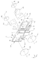
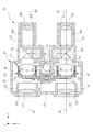
防振装置45は、手振れなどによって光学像に生じた像振れを補正するための装置である。この防振装置45は、左側対物光学系35L及び右側対物光学系35Rと、左側接眼光学系36L及び右側接眼光学系36Rとの間に配置される。図4に示すように、防振装置45は、左側防振ユニット54L、右側防振ユニット54R、リンク機構55、第1アクチュエータ56及び第2アクチュエータ57を備えている。
左側防振ユニット54Lは、左側望遠光学系37Lにおける像振れを補正する機構である。左側防振ユニット54Lは、左側対物光学系35Lと左側接眼光学系36Lとの間に配置され、左側望遠光学系37Lの一部を構成している。また、右側防振ユニット54Rは、右側望遠光学系37Rにおける像振れを補正する機構である。右側防振ユニット54Rは、右側対物光学系35Rと右側接眼光学系36Rとの間に配置され、右側望遠光学系37Rの一部を構成している。
リンク機構55は、左側防振ユニット54Lと右側防振ユニット54Rとの間を連結し、像振れ補正時に左側防振ユニット54Lと右側防振ユニット54Rとに同一の動作をさせるための機構である。第1アクチュエータ56及び第2アクチュエータ57は、左側防振ユニット54Lと右側防振ユニット54Rとの間に配置され、リンク機構55を駆動することにより、左側防振ユニット54L及び右側防振ユニット54Rを動作させる。リンク機構55を用いることにより、アクチュエータの制御が単純化できるとともに、小型化やローコスト化が可能となる。
左側正立光学系47L及び右側正立光学系47Rは、防振装置45により像振れが補正された光学像の上下左右を反転して、左側接眼光学系36L及び右側接眼光学系36Rに入射させる光学系である。左側正立光学系47L及び右側正立光学系47Rには、例えばポロプリズムやダハプリズムなどの正立プリズムが用いられる。
左側接眼鏡筒48L及び右側接眼鏡筒48Rは、円筒形状をしており、内部に左側接眼光学系36L及び右側接眼光学系36Rをそれぞれ収容している。なお、左側対物光学系35L、右側対物光学系35R、左側接眼光学系36L及び右側接眼光学系36Rは、図面の煩雑化を防ぐため、それぞれ1枚のレンズとして図示しているが、それぞれ複数枚のレンズで構成してもよい。
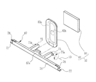
図5に示すように、左側防振ユニット54Lは、鏡枠59と、第1反射部材60と、保持板61と、第2反射部材62とを備えている。鏡枠59は、前面側及び背面側が開放された箱形状である。第1反射部材60は、鏡枠59内に固定される。保持板61は、鏡枠59内に回動自在に支持される。第2反射部材62は、保持板61の上面に固定される。第1反射部材60及び第2反射部材62には、例えば、表面反射型の反射ミラーが用いられている。なお、鏡枠59は、本発明の保持部材に相当する。
第1反射部材60は、鏡枠59内に挿入されて、反射面が下方を向くように鏡枠59の内壁上面に接着剤などで固定されている。図3に示すように、X軸方向から見た鏡枠59の内壁上面は、左側対物光学系35Lの光軸である第1光軸64aに対して45°の角度となるように傾斜されている。したがって、第1反射部材60も第1光軸64aに対して45°の角度となるように保持される。
図5に戻って、保持板61は、矩形の板状部材である。保持板61の上面には、反射面が上方を向くように、第2反射部材62が接着剤などで固定されている。保持板61の両側面には、一対の回動ピン61aが設けられている。一対の回動ピン61aは、保持板61が鏡枠59内に挿入された場合に、鏡枠59の両側面に設けられた一対の軸受け穴59aに挿入される。これにより、保持板61及び第2反射部材62は、鏡枠59内に回動自在に保持される。一対の軸受け穴59aで支持される一対の回動ピン61aは、本発明の第2回動軸12を構成する。
保持板61の下面には、下方に向かって突出されたブラケット61bが設けられている。ブラケット61bの先端には、Y軸方向に突出されて連結ピン61cが設けられている。保持板61は、連結ピン61cを介してリンク機構55により回動される。なお、保持板61は、双眼鏡30に振れが加えられていない状態(中立状態:図4及び図9の状態)では、第2反射部材62が第1反射部材60と平行になるように、リンク機構55によって角度が保持されている。
図3及び図5に示すように、鏡枠59の上面及び下面の同一のZ軸上には、一対の軸受けボス59bが設けられている。軸受けボス59bは、筐体本体50(図3参照)の内壁上面及び内壁下面に立設された一対の軸受けピン50a(図3参照)によって回動自在に支持される。これにより、鏡枠59に保持された第1反射部材60及び第2反射部材62は、Z軸周りで一体に回動可能となる。一対の軸受けボス59bにより支持される軸受けピン50aは、本発明の第1回動軸11として機能する。また、鏡枠59の前面側の上部及び下部には、一対の上部連結ボス59c及び下部連結ボス59dが、同一のZ軸上に設けられている。一対の上部連結ボス59c及び下部連結ボス59dは、リンク機構55との連結に利用される。
第1反射部材60は、左側対物光学系35Lの第1光軸64aを反射により偏向して、第1光軸64aに対して直角な第2光軸64bとする。第2光軸64bは、Z軸方向と平行である。第2反射部材62は、第2光軸64bを反射により偏向して、第1光軸64aと平行な第3光軸64cとする。第1光軸64a及び第3光軸64cは、Y軸方向と平行である。
保持板61の回動ピン61aは、第2反射部材62の反射面と第2光軸64bとの交点を通り、第1光軸64aと第2光軸64bとがなす平面に垂直な第2回動軸12として機能する。したがって、第2反射部材62は、回動ピン61aの周りで回動することにより、第3光軸64cの偏向方向を変更し、ピッチ方向の像振れを補正することができる。
鏡枠59の軸受けボス59bは、第2光軸64bと中心軸が一致する同心に設けられており、第1回動軸11として機能する。したがって、第1反射部材60及び第2反射部材62は一体で、軸受けボス59bの周りを回動して第3光軸64cの偏向方向を変更することにより、ヨー方向の像振れを補正することができる。第1回動軸11は、第1光軸64a及び第3光軸64cを含む面内にあり第1光軸64aまたは第3光軸64cに交差する。
なお、右側防振ユニット54Rは、左側防振ユニット54Lと同一の構成を有しており、左側防振ユニット54Lと同様に筐体本体50によってZ軸周りで回動自在に支持されている。また、右側防振ユニット54Rは、左側防振ユニット54Lと同様の構造でリンク機構55と連結されている。したがって、右側防振ユニット54Rの詳しい説明は省略する。
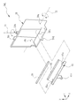
図6に示すように、リンク機構55は、第1リンク部材66と、第2リンク部材67とを備えている。第1リンク部材66は、左側防振ユニット54Lと右側防振ユニット54Rの鏡枠59同士を連結する。第1リンク部材66によって連結された左右一対の鏡枠59は、第1光軸64a同士を平行に保持した状態で並べられる。
左右一対の鏡枠59が第1リンク部材66によって連結されることにより、鏡枠59の軸受けボス59bと上部連結ボス59cとを有する枠上板と、同じく鏡枠59の軸受けボス59bと下部連結ボス59dとを有する枠下板とが中間リンクとして機能する。これら中間リンクによって第1リンク部材66をX軸方向に水平移動する4節リンク部が構成される。
第2リンク部材67は、左側防振ユニット54Lと右側防振ユニット54Rに保持される左右一対の第2反射部材62同士を連結する。第2リンク部材67は、第1リンク部材66により回動自在に支持される。
第1リンク部材66は、第1ブラケット69と、第2ブラケット70と、一対の連結部71とを備える。第1ブラケット69の下面には、鏡枠59の上部連結ボス59cに挿入される連結ピン69aが左右一対に設けられている。第2ブラケット70の上面には、鏡枠59の下部連結ボス59dに挿入される連結ピン70aが左右一対に設けられている。一対の連結部71は、第1ブラケット69と第2ブラケット70とが一体になるように垂直方向に配されている。
一対の連結部71には、鏡枠59の間で左右一対の第3ブラケット72がそれぞれ設けられている。第3ブラケット72は、Y軸方向で接眼光学系36L,36R側に突出している。第3ブラケット72には、連結穴72aが同一のX軸上にそれぞれ設けられている。また、一対の連結部71には、第3ブラケット72が設けられているのとは反対側の辺に、切欠き71aがそれぞれ設けられている。この切欠き71a内には、第2リンク部材67が収納される。
第2リンク部材67は、棒状のリンク本体74と、左右一対の連結アーム75とを備える。リンク本体74は、X軸方向に設けられている。リンク本体74には、鏡枠59の間で左右一対の連結アーム75がそれぞれ設けられている。連結アーム75は、Y軸方向で接眼光学系36L,36R側に突出している。連結アーム75は、第3ブラケット72の内側で第3ブラケット72に近接して設けられている。
連結アーム75の側面には、連結ピン75aがそれぞれ設けられている。連結ピン75aは、第1リンク部材66の第3ブラケット72に設けられた連結穴72aに挿入される。連結穴72aで支持される連結ピン75aは、本発明の第3回動軸13(図13参照)を構成する。第2リンク部材67は、第3回動軸13による連結アーム75と第3ブラケット72とが連結することにより、第3回動軸13の軸周りで回動自在となるように、第1リンク部材66によって支持される。
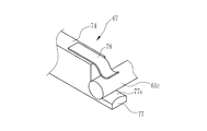
リンク本体74の両端には、当接部77がそれぞれ設けられている。当接部77は、保持板61の連結ピン61cに下方から当接する。図7に示すように、当接部77の当接面77aは円周面から構成されている。当接面77aと連結ピン61cが互いの円周面により接触することにより、第2リンク部材67が回動しても当接部77と連結ピン61cとが点接触となり、しかも相互の中心間距離は変化することがなくなる。したがって、第2リンク部材の回動を連結ピンに円滑に伝えることができる。
リンク本体74の両端には一対の付勢部材78が取り付けられている。付勢部材78は、保持板61の連結ピン61cを当接部77に当接するように付勢する。付勢部材78としては、例えば金属板からなる板バネや、トーションバネ等が用いられている。付勢部材78が連結ピン61cを付勢して当接部77が連結ピン61cと当接することにより、リンク本体74が、保持板61を介して左右一対の第2反射部材62と係合する。
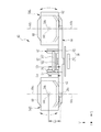
図8及び図9に示すように、リンク機構55は、第1リンク部材66をX軸方向、すなわち左側防振ユニット54L及び右側防振ユニット54Rの鏡枠59の配列方向に沿って移動させることにより、左側防振ユニット54L及び右側防振ユニット54Rの鏡枠59を、軸受けボス59bを中心にZ軸に平行な第1回動軸11周りで回動させる。これにより、左側防振ユニット54L及び右側防振ユニット54Rの第1反射部材60及び第2反射部材62がそれぞれ一体で回動するので、第3光軸64cの偏向方向が変更され、ヨー方向の像振れが補正される。
また、図10及び図11に示すように、第2リンク部材67が連結ピン75a(第3回動軸13)を中心に回動した場合には、左側防振ユニット54L及び右側防振ユニット54Rの第2反射部材62がそれぞれ回動する。これにより、第3光軸64cの偏向方向が変更され、ピッチ方向の像振れが補正される。
図6及び図8に示すように、Y軸方向における第1リンク部材66の第3ブラケット72の長さ(連結ピン69aから連結穴72aまでの長さ)Laと、同方向における第2リンク部材67の連結アーム75の長さ(リンク本体74の中心から連結ピン75aまでの長さ)Lbと、鏡枠59の上部連結ボス59cから軸受けボス59bまでの長さLcとは、同一とされている。これにより、第2回動軸12と第3回動軸13とは中心線が一致する同心に配置される。このように、防振ユニット54を第1リンク部材66で回動させる際の回動半径である長さLcと、第1反射部材60を第2リンク部材67で回動させる際の回動半径である長さLb、Lcとが同一となっているので、防振ユニット54が回動し傾いている状態でも、第2リンク部材67の回動が可能となっている。
図12に示すように、第1アクチュエータ56は、コイル基板80と、磁石81とを備えている。コイル基板80は、第1リンク部材66の取付部66aに取り付けられている。磁石81は、板状であり、コイル基板80と対面するように本体部31内に固定されている。コイル基板80には、銅線を巻いたコイル80aが設けられている。第1アクチュエータ56は、いわゆるフラットコイル式のボイスコイルモータ(Voice Coil Motor)であり、コイル80aに電流を流すことにより、磁石81の磁界の中でコイル基板80がX軸方向に移動し、第1リンク部材66を駆動する。第1アクチュエータ56の駆動により、第1リンク部材66は、X軸方向に沿って移動する。
コイル基板80には、X軸用位置センサ80bが設けられている。X軸用位置センサ80bは、コイル80aの内側にてコイル基板80のX軸方向の移動量を計測する。X軸用位置センサ80bは、例えば、ホール素子などの磁気センサであり、磁石81の磁気を検出して、磁気の強さに応じた検出信号を出力する。
図13に示すように、第2アクチュエータ57は、コイル基板83と、磁石84とを備えている。コイル基板83は、第2リンク部材67の取付部67aに取り付けられている。磁石84は、板状であり、コイル基板83と対面するように本体部31内に固定されている。コイル基板83には、コイル83aと、Z軸用位置センサ83bが設けられている。第2アクチュエータ57は、第1アクチュエータ56と同様のボイスコイルモータであり、コイル83aに電流を流すことにより、磁石84の磁界の中でコイル基板83がZ軸方向に移動し、第2リンク部材67を駆動する。第2アクチュエータ57の駆動により、第2リンク部材67は、第3回動軸13の周りに回動する。Z軸用位置センサ83bは、X軸用位置センサ80bと同様の磁気センサであり、コイル基板83のZ軸方向の移動量を計測する。
防振装置45では、第1アクチュエータ56をZ軸方向(上下方向)の下方側に寄せて配置している。なお、以降では、Z軸方向において、第1反射部材60が位置する側を上方、上端とし、第2反射部材62が位置する側を下方、下端とする。具体的には、第1アクチュエータ56は、Z軸方向において、第2反射部材62の上端面よりも低い位置に配されている。第1アクチュエータ56及び第2アクチュエータ57を構成する銅線は、比重の大きい金属線であり、防振装置45を構成する部品のなかでは、非常に重い。
また、図2に示すように、第1アクチュエータ56及び第2アクチュエータ57は、左側望遠光学系37L及び右側望遠光学系37Rの中央に位置する。さらにまた、電池収容部39に収容される電池42についても、同様に左側望遠光学系37L及び右側望遠光学系37Rの中央に位置する。なお、左側望遠光学系37L及び右側望遠光学系37Rの中央とは、X軸方向において左側望遠光学系37L及び右側望遠光学系37Rに挟まれ、且つY軸方向において左側対物光学系35L及び右側対物光学系35Rの前端と、左側接眼光学系36L及び右側接眼光学系36Rの後端との間に位置する領域をいう。
さらに詳しくは、第1アクチュエータ56は、Y軸方向において、左側対物光学系35L及び右側対物光学系35Rよりも後方、且つ第1反射部材60及び第2反射部材62よりも前方に位置する。また、第2アクチュエータ57は、左右一対の第1反射部材60及び第2反射部材62の間に位置する。また、電池42は、左側対物光学系35L及び右側対物光学系35Rの間に位置する。
図14に示すように、制御基板46に設けられている防振制御回路86は、ROM(Read Only Memory)87と、CPU(Central Processing Unit)88と、振れ量測定センサ89と、ドライバ90、91とを備える。ROM87には、制御プログラムが記憶されている。CPU88は、制御プログラムに基づいて防振装置45を制御する。振れ量測定センサ89は、双眼鏡30のX軸周り及びZ軸周りの振れ量を測定する。ドライバ90、91は、第1アクチュエータ56及び第2アクチュエータ57をそれぞれ駆動する。CPU88には、電源スイッチ41、X軸用位置センサ80b及びZ軸用位置センサ83bが接続されている。
図15に示すように、防振装置45では、第2反射部材62の裏面側(反射面とは反対側)の位置に第1リンク部材66及び第2リンク部材67が配されている。詳しくは、鏡枠59を第2回動軸12と平行な方向から視た場合に、第2反射部材62と、上下方向において第2反射部材62の下端を通る下端面と、前後方向において第2反射部材62の前端を通る前端面とに囲まれる三角形の領域E2(網掛けで示す領域であり、且つ第2反射部材62と接する領域)に、第1リンク部材66及び第2リンク部材67の少なくとも一部が配されている。
さらに詳しくは、三角形の領域E2には、第1リンク部材66の第2ブラケット70の一部が配されている。また、三角形の領域E2には、第2リンク部材67のリンク本体74及び当接部77の一部が配されている。
次に、上記実施形態の作用について説明する。防振制御回路86は、電源スイッチ41のオン操作により作動を開始する。振れ量測定センサ89は、双眼鏡30のX軸周り及びZ軸周りの振れを検出し、検出信号をCPU88に出力する。CPU88は、振れ量測定センサ89の検出信号と、X軸用位置センサ80b及びZ軸用位置センサ83bにより検出したコイル基板80及びコイル基板83の位置情報とに基づき、ドライバ90、91を制御し、光学像の像振れが補正されるように第1アクチュエータ56及び第2アクチュエータ57を駆動させる。
双眼鏡30に対し、ピッチ方向の像振れが発生している場合、CPU88は、第2アクチュエータ57のコイル基板83をZ軸方向に移動させる。コイル基板83の移動により、第2リンク部材67が連結アーム75の連結ピン75aを中心に回動する。この回動により、左側防振ユニット54L及び右側防振ユニット54Rの各第2反射部材62は、それぞれ回動ピン61aを中心として、X軸周りに回動される。これにより、第3光軸64cの偏向方向が変更されるので、ピッチ方向の像振れが補正される。
双眼鏡30に対し、ヨー方向の像振れが発生している場合には、CPU88は、第1アクチュエータ56のコイル基板80をX軸方向に移動させる。コイル基板80の移動により、第1リンク部材66がX軸方向に移動する。この移動により、左側防振ユニット54L及び右側防振ユニット54Rの各鏡枠59は、それぞれ軸受けボス59bを中心として、Z軸周りに回動される。これにより、左側防振ユニット54L及び右側防振ユニット54Rの各第1反射部材60及び第2反射部材62が一体で回動され、第3光軸64cの偏向方向が変更されるので、ヨー方向の像振れが補正される。
双眼鏡30に対し、ピッチ方向及びヨー方向の像振れが発生している場合には、CPU88は、第1アクチュエータ56及び第2アクチュエータ57を駆動させる。これにより、左側防振ユニット54L及び右側防振ユニット54Rの各第2反射部材62をX軸周りで回動させながら、左側防振ユニット54L及び右側防振ユニット54Rの各第1反射部材60及び第2反射部材62を一体でZ軸周りに回動させる。このような複合的な像振れを補正する場合でも、第1反射部材60及び第2反射部材62を一体で回動させているので、光学像が光軸を中心に回動するような現象が抑えられている。
本実施形態の防振装置45によれば、Y軸方向に対して傾斜させた第2反射部材62の裏面側の領域E2に、第1リンク部材66及び第2リンク部材67の少なくとも一部が配置されているので、防振装置45は、上下方向における寸法を抑えて小型化を図ることができる。
また、防振装置45では、第1アクチュエータ56をZ軸方向(上下方向)の下方側に寄せて配置している。防振装置45を構成する部品のうち、重量物である第1アクチュエータ56を下方側に寄せて配置しているので、重心が安定し、双眼鏡30の手振れを減少することができる。
さらにまた、第1アクチュエータ56及び第2アクチュエータ57並びに電池42は、左側望遠光学系37L及び右側望遠光学系37Rの中央に配置されているので、双眼鏡30の左右方向における手振れを減少させることができる。
なお、上記実施形態では、第2反射部材62の裏面側に第1リンク部材66及び第2リンク部材67を配しているが、本発明はこれに限るものではなく、第1反射部材60の裏面側(反射面とは反対側)に第1リンク部材66及び第2リンク部材67を配置してもよい。具体的には、鏡枠59を第2回動軸12と平行な方向から視た場合に、第1反射部材60と、上下方向において第1反射部材60の上端を通る上端面と、前後方向において第1反射部材60の後端を通る後端面とに囲まれる三角形の領域E1(図15において、網掛けで示す領域であり、且つ第1反射部材60と接する領域)に、第1リンク部材66及び第2リンク部材67の少なくとも一部が配されてもよい。これにより、上記第1実施形態と同様の効果を得ることができる。
また、上記実施形態では、本体部31の前面31aの背面側において、左側対物光学系35L及び右側対物光学系35Rの間に電池42が配されているが、これに限らず、上記実施形態よりも後方の位置、例えば、図16に示す変形例のように、第1反射部材60及び第2反射部材62の間の位置、且つ第2アクチュエータ57の後方に電池収容部95を設け、この電池収容部95に電池42を収容してもよい。これにより、重量物である第1アクチュエータ56及び第2アクチュエータ57と電池42とを、第1反射部材60及び第2反射部材62の付近に集中して配置することができるため、重心が安定し、前後方向の手振れも防ぐことができる。
なお、上記実施形態では、電池42は、円柱状に構成されているが、これに限らず、直方体状や、その他の形状であってもよい。
また、上記実施形態では、第1アクチュエータ56をZ軸方向の下方側に寄せて配置しているが、これに限らず、第1アクチュエータ56及び第2アクチュエータ57の少なくとも一方をZ軸方向のいずれか一方側に寄せて配置すればよい。
上記実施形態では、対物光学系の第1光軸に対し、第1反射部材を45°の角度で傾けることにより、第1光軸に対して偏向される第2光軸の角度を90°にしているが、この第1光軸と第2光軸とがなす角度は、90°より小さくてもまたは大きくてもよい。また、第1反射部材及び第2反射部材を一体で回動させる場合に、回動軸として第2光軸を用いたが、これに限定されるものではない。例えば、第1光軸と第1反射部材の反射面との交点を通り、かつ第1光軸と第2光軸からなる平面内の軸であれば、自由に選択可能である。
上記実施形態では、第1反射部材60を鏡枠59に固定し、第2反射部材62を保持板61に固定して回動自在に保持したが、逆に第2反射部材62を鏡枠59に固定し、保持板を介して第1反射部材を回動自在に保持してもよい。
上記実施形態では、反射部材として表面反射ミラーを用いたが、裏面反射するプリズムを反射部材として用いてもよい。上記実施形態では、複数の光軸間の位置関係を表すために直角、平行などの用語を用い、あるいは45°、90°などの具体的な数値角度を用いて説明している。しかしながら、これらは光学系において要求される精度に応じた誤差で許容される範囲を含むものである。
11 第1回動軸
12 第2回動軸
13 第3回動軸
30 双眼鏡
31 本体部
31a 前面
32L 左側対物開口
32R 及び右側対物開口
33L 左側接眼部
33R 右側接眼部
35L 左側対物光学系
35R 右側対物光学系
36L 左側接眼光学系
36R 右側接眼光学系
37L 左側望遠光学系
37R 右側望遠光学系
39 電池収容部
40 調整ノブ
41 電源スイッチ
42 電池
43 筐体
44L 左側対物鏡筒
44R 右側対物鏡筒
45 防振装置
46 制御基板
47L 左側正立光学系
47R 右側正立光学系
48L 左側接眼鏡筒
48R 右側接眼鏡筒
50 筐体本体
50a 軸受けピン
51L 左側接眼筐体
51R 右側接眼筐体
52L 左側接眼開口
52R 右側接眼開口
53 本体筐体
54 防振ユニット
54L 左側防振ユニット
54R 右側防振ユニット
55 リンク機構
56 第1アクチュエータ
57 第2アクチュエータ
59 鏡枠
59a 軸受け穴
59b 軸受けボス
59c 上部連結ボス
59d 下部連結ボス
60 第1反射部材
61 保持板
61a 回動ピン
61b ブラケット
61c 連結ピン
62 第2反射部材
64a 第1光軸
64b 第2光軸
64c 第3光軸
66 第1リンク部材
66a 取付部
67 第2リンク部材
67a 取付部
69 第1ブラケット
69a 連結ピン
70 第2ブラケット
70a 連結ピン
71 一対の連結部
71a 切欠き
72 第3ブラケット
72a 連結穴
74 リンク本体
75 連結アーム
75a 連結ピン
77 当接部
77a 当接面
78 付勢部材
80 コイル基板
80a コイル
80b 軸用位置センサ
81 磁石
83 コイル基板
83a コイル
83b 軸用位置センサ
84 磁石
86 防振制御回路
87 ROM
88 CPU
89 振れ量測定センサ
90 ドライバ
91 ドライバ
95 電池収容部
BL 左眼用光軸
BR 右眼用光軸
E1,E2 領域
La,Lb,Lc 長さ
12 第2回動軸
13 第3回動軸
30 双眼鏡
31 本体部
31a 前面
32L 左側対物開口
32R 及び右側対物開口
33L 左側接眼部
33R 右側接眼部
35L 左側対物光学系
35R 右側対物光学系
36L 左側接眼光学系
36R 右側接眼光学系
37L 左側望遠光学系
37R 右側望遠光学系
39 電池収容部
40 調整ノブ
41 電源スイッチ
42 電池
43 筐体
44L 左側対物鏡筒
44R 右側対物鏡筒
45 防振装置
46 制御基板
47L 左側正立光学系
47R 右側正立光学系
48L 左側接眼鏡筒
48R 右側接眼鏡筒
50 筐体本体
50a 軸受けピン
51L 左側接眼筐体
51R 右側接眼筐体
52L 左側接眼開口
52R 右側接眼開口
53 本体筐体
54 防振ユニット
54L 左側防振ユニット
54R 右側防振ユニット
55 リンク機構
56 第1アクチュエータ
57 第2アクチュエータ
59 鏡枠
59a 軸受け穴
59b 軸受けボス
59c 上部連結ボス
59d 下部連結ボス
60 第1反射部材
61 保持板
61a 回動ピン
61b ブラケット
61c 連結ピン
62 第2反射部材
64a 第1光軸
64b 第2光軸
64c 第3光軸
66 第1リンク部材
66a 取付部
67 第2リンク部材
67a 取付部
69 第1ブラケット
69a 連結ピン
70 第2ブラケット
70a 連結ピン
71 一対の連結部
71a 切欠き
72 第3ブラケット
72a 連結穴
74 リンク本体
75 連結アーム
75a 連結ピン
77 当接部
77a 当接面
78 付勢部材
80 コイル基板
80a コイル
80b 軸用位置センサ
81 磁石
83 コイル基板
83a コイル
83b 軸用位置センサ
84 磁石
86 防振制御回路
87 ROM
88 CPU
89 振れ量測定センサ
90 ドライバ
91 ドライバ
95 電池収容部
BL 左眼用光軸
BR 右眼用光軸
E1,E2 領域
La,Lb,Lc 長さ
Claims (8)
- 左右一対の望遠光学系を構成し、互いの光軸を平行に左右一対で並べた対物光学系と接眼光学系との間に配置される防振装置であって、
前記対物光学系の第1光軸に対して傾斜して配置され、前記左右一対で並べた対物光学系の前記第1光軸を偏向して第2光軸とする左右一対の第1反射部材と、
前記第2光軸に対して傾斜して配置され、前記第2光軸を偏向して前記第1光軸と平行な第3光軸とする左右一対の第2反射部材と、
前記第1反射部材と前記第2反射部材とを保持し、前記第2光軸と同心の第1回動軸の周りに回動自在に配置された左右一対の保持部材であって、前記第1反射部材と前記第2反射部材とのうち、一方を固定状態に保持し、他方を前記第1光軸と前記第2光軸がなす平面に垂直な第2回動軸の周りに回動自在に保持する左右一対の保持部材と、
左右一対の前記保持部材を前記第1光軸同士を平行に保持した状態で並べて、前記第1回動軸の周りに前記保持部材を回動させる第1リンク部材と、
前記第1リンク部材を前記保持部材の配列方向に移動させる第1アクチュエータと、
前記第2回動軸と平行な第3回動軸の周りで前記第1リンク部材に回動自在に保持され、左右一対の前記他方の反射部材に係合して前記他方の反射部材を回動させる第2リンク部材と、
前記第2リンク部材を前記第3回動軸の周りに回動させる第2アクチュエータとを備え、
前記第2光軸と平行な方向を上下方向、前記第1及び第3光軸と平行な方向を前後方向とし、前記保持部材を前記第2回動軸と平行な方向から視た場合に、前記第1反射部材、及び上下方向において前記第1反射部材の上端を通る上端面、並びに前後方向において前記第1反射部材の後端を通る後端面に囲まれる三角形、または、前記第2反射部材、及び上下方向において前記第2反射部材の下端を通る下端面、並びに前後方向において前記第2反射部材の前端を通る前端面に囲まれる三角形の領域に、前記第1及び第2リンク部材の少なくとも一部が配されている防振装置。 - 前記第1アクチュエータ及び前記第2アクチュエータの少なくとも一方を、上下方向のいずれか一方側に寄せて配置した請求項1記載の防振装置。
- 前記第1アクチュエータ及び前記第2アクチュエータは、前記左右一対の望遠光学系の中央に位置する請求項1または請求項2記載の防振装置。
- 前記第2リンク部材は、左右一対の前記第2反射部材を回動させる請求項1ないし3のいずれか1項記載の防振装置。
- 前記第1アクチュエータ及び前記第2アクチュエータの電源となる電池を備え、前記電池は、前記左右一対の望遠光学系の中央に位置する請求項1ないし4のいずれか1項記載の防振装置。
- 前記第1アクチュエータ及び前記第2アクチュエータは、それぞれ磁石及びコイルを有するボイスコイルモータであり、
前記第1アクチュエータのコイルが前記第1リンク部材に固定され、前記第2アクチュエータのコイルが前記第2リンク部材に固定される請求項1ないし5のいずれか1項記載の防振装置。 - 正の合成焦点距離を有する前記対物光学系と、前記接眼光学系とを備え、前記対物光学系と前記接眼光学系との間に、請求項1ないし6のいずれか1項記載の防振装置が設けられている双眼鏡。
- 前記接眼光学系は、正の合成焦点距離を有し、前記防振装置と前記接眼光学系との間には、光学像の上下左右を反転する正立光学系が設けられている請求項7に記載の双眼鏡。
Priority Applications (3)
| Application Number | Priority Date | Filing Date | Title |
|---|---|---|---|
| JP2017557804A JP6395957B2 (ja) | 2015-12-25 | 2016-11-21 | 防振装置及び双眼鏡 |
| CN201690001478.9U CN208569183U (zh) | 2015-12-25 | 2016-11-21 | 防振装置及双筒望远镜 |
| US16/016,003 US10890780B2 (en) | 2015-12-25 | 2018-06-22 | Anti-vibration device and binocle |
Applications Claiming Priority (2)
| Application Number | Priority Date | Filing Date | Title |
|---|---|---|---|
| JP2015-253275 | 2015-12-25 | ||
| JP2015253275 | 2015-12-25 |
Related Child Applications (1)
| Application Number | Title | Priority Date | Filing Date |
|---|---|---|---|
| US16/016,003 Continuation US10890780B2 (en) | 2015-12-25 | 2018-06-22 | Anti-vibration device and binocle |
Publications (1)
| Publication Number | Publication Date |
|---|---|
| WO2017110341A1 true WO2017110341A1 (ja) | 2017-06-29 |
Family
ID=59089286
Family Applications (1)
| Application Number | Title | Priority Date | Filing Date |
|---|---|---|---|
| PCT/JP2016/084471 Ceased WO2017110341A1 (ja) | 2015-12-25 | 2016-11-21 | 防振装置及び双眼鏡 |
Country Status (4)
| Country | Link |
|---|---|
| US (1) | US10890780B2 (ja) |
| JP (1) | JP6395957B2 (ja) |
| CN (1) | CN208569183U (ja) |
| WO (1) | WO2017110341A1 (ja) |
Cited By (2)
| Publication number | Priority date | Publication date | Assignee | Title |
|---|---|---|---|---|
| EP3779550A4 (en) * | 2018-04-25 | 2021-12-08 | Huawei Technologies Co., Ltd. | LENS MODULE AND CAMERA |
| WO2022113463A1 (ja) * | 2020-11-27 | 2022-06-02 | 株式会社村田製作所 | 位置検出装置 |
Families Citing this family (1)
| Publication number | Priority date | Publication date | Assignee | Title |
|---|---|---|---|---|
| WO2017146000A1 (ja) * | 2016-02-24 | 2017-08-31 | 富士フイルム株式会社 | 駆動装置及び防振装置並びに双眼鏡 |
Citations (4)
| Publication number | Priority date | Publication date | Assignee | Title |
|---|---|---|---|---|
| JPH06250098A (ja) * | 1993-02-24 | 1994-09-09 | Fuji Photo Optical Co Ltd | 像安定化装置 |
| JPH10333201A (ja) * | 1997-05-30 | 1998-12-18 | Canon Inc | 像ぶれ防止装置およびこれを備えた双眼装置 |
| JPH11295774A (ja) * | 1998-04-08 | 1999-10-29 | Canon Inc | 防振機構を備えた双眼鏡 |
| JPH11305276A (ja) * | 1998-04-20 | 1999-11-05 | Asahi Optical Co Ltd | 像振れ補正カメラ及びカメラの像振れ補正方法 |
Family Cites Families (7)
| Publication number | Priority date | Publication date | Assignee | Title |
|---|---|---|---|---|
| US3468595A (en) * | 1966-08-29 | 1969-09-23 | Optical Res & Dev Corp | Optical stabilization by reflecting means |
| US6130993A (en) | 1998-04-20 | 2000-10-10 | Asahi Kogaku Kogyo Kabushiki Kaisha | Camera having an image stabilizer |
| US10222606B2 (en) * | 2012-01-23 | 2019-03-05 | Nikon Corporation | Telescopic optical system and optical apparatus |
| JP2016095490A (ja) * | 2014-11-10 | 2016-05-26 | 富士フイルム株式会社 | 光学系、観察光学系および光学装置 |
| JP6378455B2 (ja) * | 2015-12-25 | 2018-08-22 | 富士フイルム株式会社 | 防振装置及び双眼鏡 |
| WO2017146000A1 (ja) * | 2016-02-24 | 2017-08-31 | 富士フイルム株式会社 | 駆動装置及び防振装置並びに双眼鏡 |
| CN208999653U (zh) * | 2016-02-26 | 2019-06-18 | 富士胶片株式会社 | 双筒望远镜及其操作开关 |
-
2016
- 2016-11-21 WO PCT/JP2016/084471 patent/WO2017110341A1/ja not_active Ceased
- 2016-11-21 CN CN201690001478.9U patent/CN208569183U/zh active Active
- 2016-11-21 JP JP2017557804A patent/JP6395957B2/ja active Active
-
2018
- 2018-06-22 US US16/016,003 patent/US10890780B2/en active Active
Patent Citations (4)
| Publication number | Priority date | Publication date | Assignee | Title |
|---|---|---|---|---|
| JPH06250098A (ja) * | 1993-02-24 | 1994-09-09 | Fuji Photo Optical Co Ltd | 像安定化装置 |
| JPH10333201A (ja) * | 1997-05-30 | 1998-12-18 | Canon Inc | 像ぶれ防止装置およびこれを備えた双眼装置 |
| JPH11295774A (ja) * | 1998-04-08 | 1999-10-29 | Canon Inc | 防振機構を備えた双眼鏡 |
| JPH11305276A (ja) * | 1998-04-20 | 1999-11-05 | Asahi Optical Co Ltd | 像振れ補正カメラ及びカメラの像振れ補正方法 |
Cited By (3)
| Publication number | Priority date | Publication date | Assignee | Title |
|---|---|---|---|---|
| EP3779550A4 (en) * | 2018-04-25 | 2021-12-08 | Huawei Technologies Co., Ltd. | LENS MODULE AND CAMERA |
| US12047663B2 (en) | 2018-04-25 | 2024-07-23 | Huawei Technologies Co., Ltd. | Lens module and camera |
| WO2022113463A1 (ja) * | 2020-11-27 | 2022-06-02 | 株式会社村田製作所 | 位置検出装置 |
Also Published As
| Publication number | Publication date |
|---|---|
| JPWO2017110341A1 (ja) | 2018-09-20 |
| US20180299691A1 (en) | 2018-10-18 |
| US10890780B2 (en) | 2021-01-12 |
| CN208569183U (zh) | 2019-03-01 |
| JP6395957B2 (ja) | 2018-09-26 |
Similar Documents
| Publication | Publication Date | Title |
|---|---|---|
| JP6280218B2 (ja) | 防振光学系、望遠光学系、双眼鏡、及び防振ユニット | |
| US10884214B2 (en) | Binocle and operation switch thereof having operation member and switch main body | |
| JP6395957B2 (ja) | 防振装置及び双眼鏡 | |
| JP6442640B2 (ja) | 防振装置及び双眼鏡 | |
| JP6378455B2 (ja) | 防振装置及び双眼鏡 | |
| JP3231687B2 (ja) | 手振れ補正機構を有する双眼装置及び単眼装置 | |
| JP2002202464A (ja) | 双眼振れ補正装置および双眼光学機器 | |
| JP2010097001A (ja) | 双眼鏡 | |
| JP2011069929A (ja) | 双眼鏡 | |
| JPH11295774A (ja) | 防振機構を備えた双眼鏡 | |
| JP4677111B2 (ja) | 像振れ防止機能付き双眼鏡 | |
| JPH11167073A (ja) | 双眼装置の手振れ補正機構 | |
| JP2016029403A (ja) | 光学機器 | |
| JP2023127091A (ja) | 像安定化装置 | |
| JP2012123154A (ja) | 双眼鏡 | |
| JP2006145647A (ja) | 防振双眼鏡 | |
| JP5366565B2 (ja) | 双眼鏡 | |
| JP2007156077A (ja) | 輻輳値変更機構付き防振双眼鏡 | |
| JP2018005127A (ja) | 像振れ補正を有する光学機器 | |
| JP2003222920A (ja) | 光学機器 | |
| JP2015114472A (ja) | 光学機器 | |
| JPH08160485A (ja) | 観察用光学機器 | |
| WO2009099242A1 (ja) | 望遠鏡及び双眼ボディ部材 | |
| JP2006284743A (ja) | デジタルコンパス付き眼鏡 |
Legal Events
| Date | Code | Title | Description |
|---|---|---|---|
| 121 | Ep: the epo has been informed by wipo that ep was designated in this application |
Ref document number: 16878236 Country of ref document: EP Kind code of ref document: A1 |
|
| ENP | Entry into the national phase |
Ref document number: 2017557804 Country of ref document: JP Kind code of ref document: A |
|
| NENP | Non-entry into the national phase |
Ref country code: DE |
|
| 122 | Ep: pct application non-entry in european phase |
Ref document number: 16878236 Country of ref document: EP Kind code of ref document: A1 |