WO2017110322A1 - 蒸気タービン冷却装置 - Google Patents
蒸気タービン冷却装置 Download PDFInfo
- Publication number
- WO2017110322A1 WO2017110322A1 PCT/JP2016/084085 JP2016084085W WO2017110322A1 WO 2017110322 A1 WO2017110322 A1 WO 2017110322A1 JP 2016084085 W JP2016084085 W JP 2016084085W WO 2017110322 A1 WO2017110322 A1 WO 2017110322A1
- Authority
- WO
- WIPO (PCT)
- Prior art keywords
- steam
- pressure
- cooling
- superheated
- supply pipe
- Prior art date
- Legal status (The legal status is an assumption and is not a legal conclusion. Google has not performed a legal analysis and makes no representation as to the accuracy of the status listed.)
- Ceased
Links
Images


Classifications
-
- F—MECHANICAL ENGINEERING; LIGHTING; HEATING; WEAPONS; BLASTING
- F01—MACHINES OR ENGINES IN GENERAL; ENGINE PLANTS IN GENERAL; STEAM ENGINES
- F01D—NON-POSITIVE DISPLACEMENT MACHINES OR ENGINES, e.g. STEAM TURBINES
- F01D25/00—Component parts, details, or accessories, not provided for in, or of interest apart from, other groups
- F01D25/08—Cooling; Heating; Heat-insulation
- F01D25/12—Cooling
-
- F—MECHANICAL ENGINEERING; LIGHTING; HEATING; WEAPONS; BLASTING
- F01—MACHINES OR ENGINES IN GENERAL; ENGINE PLANTS IN GENERAL; STEAM ENGINES
- F01D—NON-POSITIVE DISPLACEMENT MACHINES OR ENGINES, e.g. STEAM TURBINES
- F01D25/00—Component parts, details, or accessories, not provided for in, or of interest apart from, other groups
- F01D25/24—Casings; Casing parts, e.g. diaphragms, casing fastenings
-
- F—MECHANICAL ENGINEERING; LIGHTING; HEATING; WEAPONS; BLASTING
- F01—MACHINES OR ENGINES IN GENERAL; ENGINE PLANTS IN GENERAL; STEAM ENGINES
- F01D—NON-POSITIVE DISPLACEMENT MACHINES OR ENGINES, e.g. STEAM TURBINES
- F01D9/00—Stators
- F01D9/02—Nozzles; Nozzle boxes; Stator blades; Guide conduits, e.g. individual nozzles
-
- F—MECHANICAL ENGINEERING; LIGHTING; HEATING; WEAPONS; BLASTING
- F01—MACHINES OR ENGINES IN GENERAL; ENGINE PLANTS IN GENERAL; STEAM ENGINES
- F01D—NON-POSITIVE DISPLACEMENT MACHINES OR ENGINES, e.g. STEAM TURBINES
- F01D9/00—Stators
- F01D9/06—Fluid supply conduits to nozzles or the like
-
- F—MECHANICAL ENGINEERING; LIGHTING; HEATING; WEAPONS; BLASTING
- F05—INDEXING SCHEMES RELATING TO ENGINES OR PUMPS IN VARIOUS SUBCLASSES OF CLASSES F01-F04
- F05D—INDEXING SCHEME FOR ASPECTS RELATING TO NON-POSITIVE-DISPLACEMENT MACHINES OR ENGINES, GAS-TURBINES OR JET-PROPULSION PLANTS
- F05D2220/00—Application
- F05D2220/30—Application in turbines
- F05D2220/31—Application in turbines in steam turbines
-
- F—MECHANICAL ENGINEERING; LIGHTING; HEATING; WEAPONS; BLASTING
- F05—INDEXING SCHEMES RELATING TO ENGINES OR PUMPS IN VARIOUS SUBCLASSES OF CLASSES F01-F04
- F05D—INDEXING SCHEME FOR ASPECTS RELATING TO NON-POSITIVE-DISPLACEMENT MACHINES OR ENGINES, GAS-TURBINES OR JET-PROPULSION PLANTS
- F05D2240/00—Components
- F05D2240/10—Stators
-
- F—MECHANICAL ENGINEERING; LIGHTING; HEATING; WEAPONS; BLASTING
- F05—INDEXING SCHEMES RELATING TO ENGINES OR PUMPS IN VARIOUS SUBCLASSES OF CLASSES F01-F04
- F05D—INDEXING SCHEME FOR ASPECTS RELATING TO NON-POSITIVE-DISPLACEMENT MACHINES OR ENGINES, GAS-TURBINES OR JET-PROPULSION PLANTS
- F05D2260/00—Function
- F05D2260/20—Heat transfer, e.g. cooling
- F05D2260/201—Heat transfer, e.g. cooling by impingement of a fluid
-
- F—MECHANICAL ENGINEERING; LIGHTING; HEATING; WEAPONS; BLASTING
- F05—INDEXING SCHEMES RELATING TO ENGINES OR PUMPS IN VARIOUS SUBCLASSES OF CLASSES F01-F04
- F05D—INDEXING SCHEME FOR ASPECTS RELATING TO NON-POSITIVE-DISPLACEMENT MACHINES OR ENGINES, GAS-TURBINES OR JET-PROPULSION PLANTS
- F05D2260/00—Function
- F05D2260/20—Heat transfer, e.g. cooling
- F05D2260/232—Heat transfer, e.g. cooling characterized by the cooling medium
- F05D2260/2322—Heat transfer, e.g. cooling characterized by the cooling medium steam
-
- Y—GENERAL TAGGING OF NEW TECHNOLOGICAL DEVELOPMENTS; GENERAL TAGGING OF CROSS-SECTIONAL TECHNOLOGIES SPANNING OVER SEVERAL SECTIONS OF THE IPC; TECHNICAL SUBJECTS COVERED BY FORMER USPC CROSS-REFERENCE ART COLLECTIONS [XRACs] AND DIGESTS
- Y02—TECHNOLOGIES OR APPLICATIONS FOR MITIGATION OR ADAPTATION AGAINST CLIMATE CHANGE
- Y02T—CLIMATE CHANGE MITIGATION TECHNOLOGIES RELATED TO TRANSPORTATION
- Y02T50/00—Aeronautics or air transport
- Y02T50/60—Efficient propulsion technologies, e.g. for aircraft
Definitions
- the present invention relates to a steam turbine cooling device.
- the steam turbine described in Patent Document 1 further increases the plant thermal efficiency by raising the steam temperature to an extremely high temperature, and allows the turbine components to maintain a high strength guarantee by coping with the extremely high temperature of the steam.
- the purpose is that.
- a turbine rotor provided in a double casing is provided with a turbine stage, and the turbine stage includes a nozzle box for guiding the working steam from a steam supply pipe to the turbine stage.
- the cooling steam inlet provided through the double casing between the nozzle box and the cooling steam supplied from this cooling steam inlet was distributed, and one of the distributed cooling steam was cooled outside the nozzle box.
- the double casing was cooled via a means for supplying each of the turbine stage, the turbine rotor and the double casing, and a gland provided with the other of the distributed cooling steam between the double casing and the turbine rotor.
- the steam supply pipe has a double pipe structure of an outer pipe and an inner pipe, and a cooling passage is formed between the inner pipe and the outer pipe. That is, the steam supply pipe is formed with a passage inside the inner pipe and a cooling passage between the inner pipe and the outer pipe.
- the inside of the inner pipe is connected to a nozzle box housed in the inner casing of the double casing, and the cooling passage is connected to the outer casing of the double casing. Then, the superheated steam is supplied from the inner pipe into the nozzle box and guided to the turbine stage in the inner casing by the nozzle box.
- the cooling steam is supplied from the cooling steam inlet between the turbine rotor and the nozzle box, and then one is supplied to each of the turbine stage, the turbine rotor and the inner casing through the outside of the nozzle box, and the other Are joined together in the outer casing via a gland provided between the inner casing and the turbine rotor and supplied to the cooling passage of the steam supply pipe.
- This invention solves the subject mentioned above, and aims at providing the steam turbine cooling device which can improve cooling efficiency.
- a steam turbine cooling device of the present invention includes a rotor as a rotating body that extends along the axis of rotation thereof, a casing that houses the rotor, and an extension of the rotor.
- a steam path provided between the rotor and the passenger compartment along the direction of movement, and an annular shape surrounding the outer periphery of the rotor, and communicated with the steam path between the outer surface and the outer peripheral surface of the rotor
- a steam nozzle chamber that is attached to the interior of the vehicle interior with a gap that is formed along an annular shape, and an opening that communicates with the steam passage from the steam nozzle chamber toward the extending direction of the rotor.
- a superheated steam supply pipe that is provided in communication with the steam nozzle chamber of the steam nozzle section through the casing from the outside of the casing and is supplied with superheated steam.
- a cooling steam passage that extends through the passenger compartment along the superheated steam supply pipe and reaches the gap, and reaches the gap along the superheated steam supply pipe via the cooling steam passage, and A cooling steam supply unit that supplies low-temperature cooling steam at a pressure higher than that of the steam supplied by the steam supply pipe.
- the superheated steam supplied from the superheated steam supply pipe reaches the steam passage through the opening from the steam nozzle chamber of the steam nozzle section.
- the superheated steam gradually decreases in temperature and pressure from the upstream side to the downstream side of the flow.
- the cooling steam reaches the gap along the superheated steam supply pipe via the cooling steam passage, and flows along the part from the higher temperature to the lower part with the temperature of the superheated steam. For this reason, the high temperature part can be reliably cooled by the cooling steam.
- the cooling steam reaching the steam passage from the gap becomes a temperature close to that of the superheated steam and merges with the superheated steam, so that the performance degradation of the steam turbine can be suppressed.
- the cooling steam does not disperse into a plurality of paths and follows a series of paths, the flow rate can be easily controlled during cooling.
- the cooling steam passage is between an outer pipe that surrounds an outer periphery of the superheated steam supply pipe and is attached to the vehicle compartment, and an outer peripheral surface of the superheated steam supply pipe. It is a formed space portion, and is provided from the outside of the vehicle compartment to the inside of the vehicle compartment and in communication with the gap.
- this steam turbine cooling device it is possible to realize a path that passes through the passenger compartment along the superheated steam supply pipe and reaches the gap.
- the cooling steam passage includes a space part between the outer peripheral surface of the superheated steam supply pipe and the vehicle compartment, and a steam nozzle part provided in communication with the space part.
- a hollow portion in the wall and a through-hole penetrating from the hollow portion to the gap, are provided from the outside of the vehicle compartment to the inside of the vehicle compartment and communicated with the gap.
- this steam turbine cooling device it is possible to realize a path that passes through the passenger compartment along the superheated steam supply pipe and reaches the gap.
- the cooling efficiency can be improved.
- FIG. 1 is a schematic configuration diagram illustrating an example of a combined cycle plant.
- FIG. 2 is a schematic configuration diagram illustrating an example of a steam turbine cooling device according to an embodiment of the present invention.
- FIG. 3 is a schematic configuration diagram illustrating an example of a steam turbine cooling device according to an embodiment of the present invention.
- FIG. 1 is a schematic configuration diagram illustrating an example of a combined cycle plant to which the gas turbine and the steam turbine are applied.
- a combined cycle plant 100 shown in FIG. 1 includes a gas turbine 110, a high-pressure steam turbine 120, an intermediate-pressure steam turbine 130, and a low-pressure steam turbine 140. These gas turbine 110, high-pressure steam turbine 120, intermediate-pressure steam turbine 130, and low-pressure The steam turbine 140 is disposed coaxially with the generator 150.
- the gas turbine 110 includes a compressor 111, a combustor 112, and a turbine 113.
- the compressor inlet air 114 is pressurized and supplied to the combustor 112.
- the combustor 112 high-temperature combustion gas is generated by the supplied air and fuel 115 and supplied to the turbine 113.
- the combustion gas passing through the turbine 113 is discharged as exhaust gas after the turbine 113 is driven to rotate.
- the combined cycle plant 100 includes a boiler (exhaust heat recovery boiler) 1 that generates superheated steam from water using the exhaust gas discharged from the turbine 113 in the gas turbine 110 as a heating source.
- the superheated steam generated by the boiler 1 drives the high-pressure steam turbine 120, the intermediate-pressure steam turbine 130, and the low-pressure steam turbine 140.
- Electric power is generated by the generator 150 by driving the gas turbine 110, the high pressure steam turbine 120, the intermediate pressure steam turbine 130, and the low pressure steam turbine 140.
- the steam used in the low-pressure steam turbine 140 is converted into condensate by a condenser 160 connected to the low-pressure steam turbine 140 and sent to the boiler 1 as water for generating superheated steam.
- the boiler 1 is connected to a flue 113a provided on the exhaust side of the turbine 113 in the gas turbine 110.
- the boiler 1 includes a low-pressure economizer 10, a low-pressure drum 11, a low-pressure evaporator 12, a medium-pressure economizer 13, a high-pressure primary economizer 14, an intermediate-pressure drum 15, and an intermediate-pressure evaporator from the downstream side of the exhaust gas flow.
- the boiler 1 includes a low-pressure system that generates low-pressure superheated steam for driving the low-pressure steam turbine 140, a medium-pressure system that generates medium-pressure superheated steam for driving the intermediate-pressure steam turbine 130, and high-pressure steam. And a high-pressure system that generates high-pressure superheated steam for driving the turbine 120.
- the low pressure system includes a low pressure economizer 10, a low pressure drum 11, a low pressure evaporator 12, a low pressure superheater 17, and a condensate pump 26.
- the intermediate pressure system includes an intermediate pressure economizer 13, an intermediate pressure drum 15, an intermediate pressure evaporator 16, an intermediate pressure superheater 19, a primary reheater 23, a secondary reheater 24, and an intermediate pressure feed water pump 27.
- the high-pressure system includes a high-pressure primary economizer 14, a high-pressure secondary economizer 18, a high-pressure drum 20, a high-pressure evaporator 21, a high-pressure primary superheater 22, a high-pressure secondary superheater 25, and a high-pressure feed water pump 28.
- the low pressure economizer 10 is connected to the condenser 160 through the connection line 30.
- a condensate pump 26 is provided in the connection line 30.
- the low-pressure economizer 10 is connected to the low-pressure drum 11 through a low-pressure branch line 31a among the connection lines 31 branched into three.
- the low pressure drum 11 is connected to the low pressure evaporator 12.
- the low-pressure drum 11 is connected to the low-pressure superheater 17 through a connection line 32.
- the low pressure superheater 17 is connected to the inlet side of the low pressure steam turbine 140 through the connection line 33.
- the outlet side of the low-pressure steam turbine 140 is connected to the condenser 160 through the connection line 34.
- the water (condensate) of the condenser 160 flows into the low-pressure economizer 10 through the connection line 30 and is heated by the condensate pump 26 and is heated through the low-pressure branch line 31 a of the connection line 31. It flows into the drum 11.
- the water supplied to the low-pressure drum 11 is evaporated by the low-pressure evaporator 12 to become saturated steam, returned to the low-pressure drum 11, and sent to the low-pressure superheater 17 through the connection line 32.
- the saturated steam is superheated in the low-pressure superheater 17, and this superheated steam is supplied to the low-pressure steam turbine 140 through the connection line 33.
- the steam discharged by driving the low-pressure steam turbine 140 is guided to the condenser 160 through the connection line 34 to become water (condensate), and is supplied to the low-pressure economizer 10 through the connection line 30 by the condensate pump 26. Sent out.
- the medium pressure economizer 13 is connected to the low pressure economizer 10 by an intermediate pressure branch line 31b among the connection lines 31 that branch into three.
- An intermediate pressure feed water pump 27 is provided in the intermediate pressure branch line 31b.
- the intermediate pressure economizer 13 is connected to the intermediate pressure drum 15 through a connection line 35.
- the connection line 35 is provided with a flow rate adjusting valve 36 on the way.
- the intermediate pressure drum 15 is connected to the intermediate pressure evaporator 16. Further, the intermediate pressure drum 15 is connected to the intermediate pressure superheater 19 through a connection line 37.
- the intermediate pressure superheater 19 is connected to the inlet side of the primary reheater 23 by a connection line 38.
- the primary reheater 23 is connected to the outlet side of the high-pressure steam turbine 120 through the connection line 40. Further, the primary reheater 23 is connected to the secondary reheater 24 by a connection line 41. The secondary reheater 24 is connected to the inlet side of the intermediate pressure steam turbine 130 through the connection line 42. The outlet side of the intermediate pressure steam turbine 130 is connected to the inlet side of the low pressure steam turbine 140 through a connection line 39.
- the water heated by the low pressure economizer 10 is further heated by flowing into the intermediate pressure economizer 13 via the intermediate pressure branch line 31b of the connection line 31 by the intermediate pressure feed water pump 27. It flows into the intermediate pressure drum 15 via the line 35.
- the water supplied to the intermediate pressure drum 15 is evaporated by the intermediate pressure evaporator 16 to become saturated vapor, returned to the intermediate pressure drum 15, and sent to the intermediate pressure superheater 19 through the connection line 37.
- the saturated steam is superheated in the intermediate pressure superheater 19, and this superheated steam is supplied to the primary reheater 23 via the connection line 38.
- the steam discharged by driving the high-pressure steam turbine 120 is sent to the primary reheater 23 through the connection line 40.
- the steam is superheated in the primary reheater 23, and this superheated steam is sent to the secondary reheater 24 through the connection line 41.
- the steam is further superheated in the secondary reheater 24, and this superheated steam is supplied to the intermediate pressure steam turbine 130 via the connection line 42.
- the steam discharged by driving the intermediate pressure steam turbine 130 is supplied to the low pressure steam turbine 140 through the connection line 39.
- the primary reheater 23 and the secondary reheater 24 superheat steam, they have the same function as the superheater and are included in the superheater in this embodiment. That is, the primary reheater 23 is also referred to as a first superheater, and the secondary reheater 24 is also referred to as a second superheater.
- the high-pressure primary economizer 14 is connected to the low-pressure economizer 10 by a high-pressure branch line 31c among the connection lines 31 that branch into three.
- a high-pressure feed water pump 28 is provided in the high-pressure branch line 31c.
- the high-pressure primary economizer 14 is connected to the high-pressure secondary economizer 18 through a connection line 43.
- the high pressure secondary economizer 18 is connected to the high pressure drum 20 via a connection line 44.
- the connection line 44 is provided with a flow rate adjustment valve 45 in the middle.
- the high pressure drum 20 is connected to a high pressure evaporator 21.
- the high-pressure drum 20 is connected to the high-pressure primary superheater 22 through a connection line 46.
- the high-pressure primary superheater 22 is connected to the high-pressure secondary superheater 25 by a connection line 47.
- the high pressure secondary superheater 25 is connected to the inlet side of the high pressure steam turbine 120 by a connection line 48.
- the outlet side of the high-pressure steam turbine 120 is connected to the intermediate pressure primary reheater 23 through the connection line 40 as described above.
- the water heated in the low-pressure economizer 10 is further heated by flowing into the high-pressure primary economizer 14 via the high-pressure branch line 31 c of the connection line 31 by the high-pressure feed water pump 28. Then, it flows into the high-pressure secondary economizer 18 and is further heated and flows into the high-pressure drum 20 through the connection line 44.
- the water supplied to the high-pressure drum 20 is evaporated by the high-pressure evaporator 21 to become saturated steam, returned to the high-pressure drum 20, and sent to the high-pressure primary superheater 22 through the connection line 46.
- the saturated steam is superheated in the high-pressure primary superheater 22, and this superheated steam is sent to the high-pressure secondary superheater 25 through the connection line 47.
- the superheated steam is further superheated in the high pressure secondary superheater 25, and this superheated steam is supplied to the high pressure steam turbine 120 via the connection line 48.
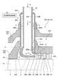
- FIG 2 and 3 are schematic configuration diagrams showing an example of the steam turbine cooling device according to the present embodiment.
- the steam turbines 120, 130, and 140 include a rotor 61, a casing 62, a steam passage 63, a steam nozzle portion 64 ⁇ / b> A, stationary blades 66 ⁇ / b> A and 66 ⁇ / b> B, and a moving blade 67. And a superheated steam supply pipe 69A.
- the rotor 61 is provided so as to extend along the axis S of its own rotation.
- the vehicle compartment 62 houses the rotor 61 and supports the rotor 61 so as to be rotatable around the axis S.
- the vehicle compartment 62 includes an outer vehicle compartment 62A and an inner vehicle compartment 62B.
- the outer casing 62A covers the periphery of the inner casing 62B and stores the inner casing 62B.
- the inner casing 62B houses the rotor 61 and supports the rotor 61 so as to be rotatable around the axis S.
- a vehicle interior space 62C is formed between the outer vehicle compartment 62A and the inner vehicle compartment 62B.
- a clearance 65A is formed between the inner casing 62B and the outer peripheral surface of the rotor 61.
- the gap 65A is provided with a plurality of fins 68 extending from the inner casing 62B toward the rotor 61 and arranged in the extending direction of the rotor 61.
- the fin 68 is applied to a labyrinth seal, a brush seal, or a leaf-like seal, and prevents fluid from leaking out in the gap 65A.
- the steam passage 63 is an annular space provided between the rotor 61 and the inner casing 62B along the extending direction of the rotor 61.
- the steam nozzle portion 64A is formed in an annular shape so as to surround the outer periphery of the rotor 61, and is partitioned by the outer peripheral surface of the steam nozzle portion 64A, the outer peripheral surface of the rotor 61, and the inner peripheral surface of the inner casing 62B.
- a gap 65B communicating with the passage 63 and the gap 65A is attached to the inner casing 62B.
- the steam nozzle portion 64 ⁇ / b> A includes a steam nozzle chamber 64 ⁇ / b> Aa formed in an annular shape therein, and an opening 64 ⁇ / b> Ab that leads from the steam nozzle chamber 64 ⁇ / b> Aa in the extending direction of the rotor 61 to the steam passage 63.
- a plurality of nozzle portion stationary blades 66A are attached to the opening 64Ab of the steam nozzle chamber 64Aa along an annular shape.
- a plurality of steam passage vanes 66B are attached to the inner casing 62B along an annular shape.
- a plurality of moving blades 67 are attached to the outer periphery of the rotor 61 along the annular shape adjacent to the stationary blades 66A and 66B.
- the superheated steam supply pipe 69A is provided to communicate with the steam nozzle chamber 64Aa of the steam nozzle portion 64A from the outside of the outer casing 62A and the inner casing 62B through the casings 62A and 62B, and is overheated.
- the superheated steam G is supplied to the steam passage 63 through the steam nozzle portion 64A.
- the superheated steam supply pipe 69 ⁇ / b> A is connected to the connection line 48 shown in FIG. 1, and is supplied with the superheated steam G that has been superheated by the high-pressure secondary superheater 25.
- the superheated steam supply pipe 69 ⁇ / b> A is connected to the connection line 42 shown in FIG. 1 in the case of the intermediate pressure steam turbine 130, and is supplied with the superheated steam G superheated by the secondary reheater 24. Further, in the case of the low pressure steam turbine 140, the superheated steam supply pipe 69A is connected to the connection line 33 shown in FIG. 1 and supplied with the superheated steam G that has been superheated by the low pressure superheater 17.
- the superheated steam G heated to the steam nozzle chamber 64Aa is supplied to the steam turbines 120, 130, and 140, and is discharged from the opening 64Ab to the steam passage 63, and the rotor 61 is rotated by the stationary blades 66A and 66B and the moving blade 67. To do.
- the steam turbine cooling device of the present embodiment is configured in the form shown in FIGS.
- FIG. 2 includes a cooling steam passage 69Ba and a cooling steam supply unit 70.
- the cooling steam passage 69Ba passes through the vehicle compartment 62 (the outer vehicle compartment 62A and the inner vehicle compartment 62B) along the superheated steam supply pipe 69A and reaches the clearance 65B on the outer periphery of the steam nozzle portion 64A. Further, the cooling steam supply unit 70 has a higher pressure than the superheated steam G supplied from the superheated steam supply pipe 69A to the clearance 65B on the outer periphery of the steam nozzle part 64A from the superheated steam supply pipe 69A side with respect to the cooling steam passage 69Ba. To supply low-temperature cooling steam C.
- the cooling steam passage 69Ba is formed between a cylindrical outer pipe 69B that surrounds the outer periphery of the superheated steam supply pipe 69A and attached to the vehicle compartment 62, and an outer peripheral surface of the superheated steam supply pipe 69A. It is a space part.
- the outer pipe 69B is closed by connecting a base end portion located outside the outer casing 62A to the outer peripheral surface of the superheated steam supply pipe 69A, and a connection port 69C through which the cooling steam supply section 70 communicates is formed at this position. ing.
- the outer pipe 69B has a distal end disposed inside the inner casing 62B, and a cooling steam passage 69Ba is provided outside the steam nozzle section 64A and opened inside the inner casing 62B.
- the cooling steam passage 69Ba is configured as a double pipe 69 with a superheated steam supply pipe 69A and an outer pipe 69B surrounding the outer periphery of the superheated steam supply pipe 69A.
- the interior of the inner casing 62B is communicated from the outside of the chamber 62A to the clearance 65B on the outer periphery of the steam nozzle portion 64A.
- the cooling steam supply unit 70 extends from the outlet of the high-pressure evaporator 21 (high-pressure drum 20) in the combined cycle plant 100 to the inside of the high-pressure secondary superheater 25 through the high-pressure primary superheater 22. It becomes a supply source, and the supply source is connected to the cooling steam passage 69Ba by a connection line (not shown).
- the superheated steam G supplied to the high-pressure steam turbine 120 passes through the connection line 48 from the high-pressure secondary superheater 25, but the pressure decreases in the process of passing through the connection line 48.
- the steam from the outlet of the high pressure evaporator 21 to the inside of the high pressure secondary superheater 25 through the high pressure primary superheater 22 has a higher pressure and a lower temperature than the superheated steam G supplied to the high pressure steam turbine 120. is there. Accordingly, it is possible to supply the cooling steam C having a higher pressure and lower temperature than the superheated steam G supplied to the high-pressure steam turbine 120 into the high-pressure steam turbine 120.
- the cooling steam supply unit 70 passes through the intermediate pressure superheater 19 and the primary reheater 23 from the outlet of the intermediate pressure evaporator 16 (intermediate pressure drum 15) in the combined cycle plant 100.
- the space up to the inside of the next reheater 24 is a supply source, and the supply source is connected to the cooling steam passage 69Ba by a connection line (not shown).
- the superheated steam G supplied to the intermediate pressure steam turbine 130 passes through the connection line 42 from the secondary reheater 24, but the pressure decreases in the process of passing through the connection line 42.
- the steam from the outlet of the intermediate pressure evaporator 16 to the inside of the secondary reheater 24 through the intermediate pressure superheater 19 and the primary reheater 23 is superheated steam G supplied to the intermediate pressure steam turbine 130. Higher pressure and lower temperature. Accordingly, it is possible to supply the cooling steam C having a pressure higher than that of the superheated steam G supplied to the intermediate pressure steam turbine 130 and a low temperature into the intermediate pressure steam turbine 130.
- the cooling steam supply unit 70 is a supply source from the outlet of the low pressure evaporator 12 (low pressure drum 11) in the combined cycle plant 100 to the inside of the low pressure superheater 17. Is connected to the cooling steam passage 69Ba by a connection line (not shown).
- the superheated steam G supplied to the low-pressure steam turbine 140 passes through the connection line 33 from the low-pressure superheater 17, but the pressure decreases in the process of passing through the connection line 33. Therefore, the steam between the outlet of the low-pressure evaporator 12 and the inside of the low-pressure superheater 17 is higher in pressure and lower in temperature than the superheated steam G supplied to the low-pressure steam turbine 140. Therefore, it is possible to supply the cooling steam C having a pressure higher than that of the superheated steam G supplied to the low-pressure steam turbine 140 and a low temperature into the low-pressure steam turbine 140.
- the steam turbine cooling device shown in FIG. 2 is superheated via the cooling steam passage 69Ba provided through the vehicle compartment 62 along the superheated steam supply pipe 69A and reaching the gap 65B, and the cooling steam passage 69Ba.
- the superheated steam G supplied from the superheated steam supply pipe 69A reaches the steam passage 63 from the steam nozzle chamber 64Aa of the steam nozzle portion 64A through the opening 64Ab.
- the superheated steam G gradually decreases in temperature and pressure from the upstream side to the downstream side of the flow.
- the cooling steam C reaches the gap 65B along the superheated steam supply pipe 69A via the cooling steam passage 69Ba, and flows along the portion where the temperature is higher from the higher temperature with the temperature of the superheated steam G. For this reason, the high temperature part can be reliably cooled by the cooling steam C.
- the cooling steam C reaching the steam passage 63 from the gap 65B becomes a temperature close to the superheated steam G and merges with the superheated steam G, the performance degradation of the steam turbines 120, 130, and 140 can be suppressed.
- the cooling steam C does not disperse into a plurality of paths and follows a series of paths, so that the flow rate can be easily controlled during cooling.
- the cooling steam passage 69Ba includes an outer pipe 69B that surrounds the outer periphery of the superheated steam supply pipe 69A and is attached to the vehicle compartment 62, and an outer peripheral surface of the superheated steam supply pipe 69A. It is a space portion formed between the interior of the compartment 62 (outer compartment 62A) and the interior of the compartment 62 (inner compartment 62B) and communicates with the gap 65B. A path that passes through the vehicle compartment 62 and reaches the gap 65B along the steam supply pipe 69A can be realized.
- the steam turbine cooling apparatus shown in FIG. 3 includes a cooling steam passage 69Ba and a cooling steam supply unit 70.
- the cooling steam passage 69Ba passes through the vehicle compartment 62 (the outer vehicle compartment 62A and the inner vehicle compartment 62B) along the superheated steam supply pipe 69A and reaches the clearance 65B on the outer periphery of the steam nozzle portion 64A. Further, the cooling steam supply unit 70 has a higher pressure than the superheated steam G supplied from the superheated steam supply pipe 69A to the clearance 65B on the outer periphery of the steam nozzle part 64A from the superheated steam supply pipe 69A side with respect to the cooling steam passage 69Ba. To supply low-temperature cooling steam C.
- the cooling steam passage 69Ba communicates with a space portion formed between the outer peripheral surface of the superheated steam supply pipe 69A and the compartment 62 (the outer compartment 62A and the inner compartment 62B), and the space portion.
- a hollow portion in the wall of the provided steam nozzle portion 64A and a through hole 69Bb penetrating from the hollow portion to the gap 65B are included.
- the cooling steam passage 69Ba as a space is formed between the outer peripheral surface of the superheated steam supply pipe 69A and the vehicle compartment 62 at a portion where the superheated steam supply pipe 69A penetrates the vehicle compartment 62, and In this portion, the outer casing 62A and the inner casing 62B are connected without a gap.
- the cooling steam passage 69Ba which is a space, is closed at the base end located outside the outer casing 62A, and a connection port 69C through which the cooling steam supply unit 70 communicates is formed at this position. Further, the cooling steam passage 69Ba that is a hollow portion communicates with the space portion.
- the cooling steam passage 69Ba which is a hollow portion, is provided with a plurality of through holes 69Bb penetrating the outer peripheral surface existing in the gap 65B in the steam nozzle part 64A, and the outside of the steam nozzle part 64A via the through hole 69Bb. In this case, the opening is provided inside the inner casing 62B. That is, in the steam turbine cooling device shown in FIG.
- the cooling steam passage 69Ba is configured along the outer peripheral surface of the superheated steam supply pipe 69A and in communication with the inside of the wall of the steam nozzle portion 64A, and is located outside the outer casing 62A. To the inside of the inner casing 62B, and communicated with a gap 65B on the outer periphery of the steam nozzle portion 64A through a through hole 69Bb.
- each supply source in the combined cycle plant 100 is connected to a cooling steam passage 69Ba (not shown). Connected).
- the steam turbine cooling device shown in FIG. 3 is superheated via the cooling steam passage 69Ba provided through the vehicle interior 62 along the superheated steam supply pipe 69A and reaching the gap 65B, and the cooling steam passage 69Ba.
- the superheated steam G supplied from the superheated steam supply pipe 69A reaches the steam passage 63 from the steam nozzle chamber 64Aa of the steam nozzle portion 64A through the opening 64Ab.
- the superheated steam G gradually decreases in temperature and pressure from the upstream side to the downstream side of the flow.
- the cooling steam C reaches the gap 65B along the superheated steam supply pipe 69A via the cooling steam passage 69Ba, and flows along the portion where the temperature is higher from the higher temperature with the temperature of the superheated steam G. For this reason, the high temperature part can be reliably cooled by the cooling steam C.
- the cooling steam C reaching the steam passage 63 from the gap 65B becomes a temperature close to the superheated steam G and merges with the superheated steam G, the performance degradation of the steam turbines 120, 130, and 140 can be suppressed.
- the cooling steam C does not disperse into a plurality of paths and follows a series of paths, so that the flow rate can be easily controlled during cooling.
- the cooling steam passage 69Ba is formed in the space between the outer peripheral surface of the superheated steam supply pipe 69A and the vehicle compartment 62 (the outer compartment 62A and the inner compartment 62B). It includes a hollow portion in the wall of the steam nozzle portion 64A provided in communication and a through hole 69Bb penetrating from the hollow portion to the gap 65B, and is provided from the outside of the vehicle compartment 62 (outer vehicle compartment 62A) to the vehicle compartment 62 ( The inner casing 62B) is provided in communication with the gap 65B.
- tube 69A and reaches the clearance gap 65B is realizable.
- the cooling steam passage 69Ba is constituted by the space between the outer peripheral surface of the superheated steam supply pipe 69A and the vehicle compartment 62 (the outer compartment 62A and the inner compartment 62B). Therefore, unlike the steam turbine cooling device shown in FIG. 2, the double pipe 69 in which the outer pipe 69B is provided outside the superheated steam supply pipe 69A becomes unnecessary. Moreover, cooling efficiency can be improved compared with cooling from the surface by cooling the steam nozzle part 64A from the inside by the hollow part. Further, the through hole 69Bb has a nozzle shape, and the cooling effect of the rotor 61 can be expected by blowing the cooling steam C onto the rotor 61.
- the steam turbine cooling device of the present embodiment is configured so that, in the combined cycle plant 100, the steam turbine 120, 130 supplies the cooling steam C having a pressure higher than that of the superheated steam G supplied to the steam turbines 120, 130, 140 and a low temperature. , 140 can be supplied. As a result, a separate power source is not required, and the high temperature part inside the steam turbine 120, 130, 140 can be cooled. Further, since the steam generated in the combined cycle plant 100 is used and the fluid inside the steam turbines 120, 130, 140 is not used, the operating efficiency of the steam turbines 120, 130, 140 is prevented from being lowered, and as a result, the cycle efficiency is lowered. Can be prevented.
- the cooling steam supply unit 70 that supplies the cooling steam C is from the outlet of the high pressure primary superheater 22 to the inlet of the high pressure secondary superheater 25 in the case of the high pressure steam turbine 120. It is preferable that the gap be a supply source, and the supply source is connected to the cooling steam passage 69Ba by a connection line (not shown).
- the cooling steam C is supplied to the inside of the high-pressure steam turbine 120 from the connection line 47 between the outlet of the high-pressure primary superheater 22 and the inlet of the high-pressure secondary superheater 25, the steam supplied to the high-pressure secondary superheater 25 is supplied.
- the superheat efficiency in the high pressure secondary superheater 25 is improved, and the temperature of the superheated steam G supplied to the high pressure steam turbine 120 is increased.
- the operating efficiency of the high-pressure steam turbine 120 can be improved, and the cycle efficiency can be improved.
- the cooling steam C is supplied into the high-pressure steam turbine 120 from the connection line 47 between the outlet of the high-pressure primary superheater 22 and the inlet of the high-pressure secondary superheater 25, the superheated steam supplied to the high-pressure steam turbine 120 is supplied.
- the temperature of G is made constant, the amount of steam obtained from the high-pressure evaporator 21 can be increased, so that the amount of superheated steam G supplied to the high-pressure steam turbine 120 can be increased.
- the operating efficiency of the high-pressure steam turbine 120 can be improved, and the cycle efficiency can be improved.
- the cooling steam supply unit 70 that supplies the cooling steam C is from the outlet of the intermediate pressure superheater 19 to the inlet of the primary reheater 23 in the case of the intermediate pressure steam turbine 130.
- the gap be a supply source, and the supply source is connected to the cooling steam passage 69Ba by a connection line (not shown).
- the superheat efficiency in the primary reheater 23 and the secondary reheater 24 is improved, and the temperature of the superheated steam G supplied to the intermediate pressure steam turbine 130. Rises. As a result, the operation efficiency of the intermediate pressure steam turbine 130 can be improved, and the cycle efficiency can be improved.
- the cooling steam C is supplied to the inside of the intermediate pressure steam turbine 130 from the connection line 38 (and a part of the connection line 40) between the outlet of the intermediate pressure superheater 19 and the inlet of the primary reheater 23
- the temperature of the superheated steam G supplied to the intermediate pressure steam turbine 130 is constant, the amount of steam obtained from the intermediate pressure evaporator 16 can be increased. Can be increased. As a result, the operation efficiency of the intermediate pressure steam turbine 130 can be improved, and the cycle efficiency can be improved.
- the cooling steam supply unit 70 that supplies the cooling steam C is from the outlet of the primary reheater 23 to the inlet of the secondary reheater 24 in the case of the intermediate pressure steam turbine 130.
- the supply source is preferably connected to the cooling steam passage 69Ba by a connection line (not shown).
- the operation efficiency of the intermediate pressure steam turbine 130 can be improved, and the cycle efficiency can be improved.
- the cooling steam C is supplied to the inside of the intermediate pressure steam turbine 130 from the connection line 41 between the outlet of the primary reheater 23 and the inlet of the secondary reheater 24, the cooling steam C is supplied to the intermediate pressure steam turbine 130.
- the temperature of the superheated steam G is kept constant, the amount of steam obtained from the intermediate pressure evaporator 16 can be increased, so that the amount of superheated steam G supplied to the intermediate pressure steam turbine 130 can be increased.
- the operation efficiency of the intermediate pressure steam turbine 130 can be improved, and the cycle efficiency can be improved.
- the cooling steam supply unit 70 that supplies the cooling steam C supplies the space from the outlet of the low-pressure evaporator 12 to the inlet of the low-pressure superheater 17 in the case of the low-pressure steam turbine 140.
- the supply source is preferably connected to the cooling steam passage 69Ba by a connection line (not shown).
- the operating efficiency of the low-pressure steam turbine 140 can be improved, and the cycle efficiency can be improved.
- the cooling steam C is supplied into the low-pressure steam turbine 140 from the connection line 32 between the outlet of the low-pressure evaporator 12 and the inlet of the low-pressure superheater 17, the temperature of the superheated steam G supplied to the low-pressure steam turbine 140.
- the amount of steam obtained from the low pressure evaporator 12 can be increased, so that the amount of superheated steam G supplied to the low pressure steam turbine 140 can be increased.
- the operating efficiency of the low-pressure steam turbine 140 can be improved, and the cycle efficiency can be improved.
Landscapes
- Engineering & Computer Science (AREA)
- Mechanical Engineering (AREA)
- General Engineering & Computer Science (AREA)
- Engine Equipment That Uses Special Cycles (AREA)
- Turbine Rotor Nozzle Sealing (AREA)
Abstract
Description
10 低圧節炭器
11 低圧ドラム
12 低圧蒸発器
13 中圧節炭器
14 高圧一次節炭器
15 中圧ドラム
16 中圧蒸発器
17 低圧過熱器
18 高圧二次節炭器
19 中圧過熱器
20 高圧ドラム
21 高圧蒸発器
22 高圧一次過熱器
23 一次再熱器
24 二次再熱器
25 高圧二次過熱器
26 復水ポンプ
27 中圧給水ポンプ
28 高圧給水ポンプ
30 接続ライン
31 接続ライン
31a 低圧分岐ライン
31b 中圧分岐ライン
31c 高圧分岐ライン
32 接続ライン
33 接続ライン
34 接続ライン
35 接続ライン
36 流量調整弁
37 接続ライン
38 接続ライン
39 接続ライン
40 接続ライン
41 接続ライン
42 接続ライン
43 接続ライン
44 接続ライン
45 流量調整弁
46 接続ライン
47 接続ライン
48 接続ライン
61 ロータ
62 車室
62A 外側車室
62B 内側車室
62C 車室空間部
63 蒸気通路
64A 蒸気ノズル部
64Aa 蒸気ノズル室
64Ab 開口
65A 隙間
65B 隙間
66A ノズル部静翼
66B 蒸気通路静翼
67 動翼
68 フィン
69 二重管
69A 過熱蒸気供給管
69B 外管
69Ba 冷却蒸気通路
69Bb 貫通孔
69C 接続口
70 冷却蒸気供給部
100 コンバインドサイクルプラント
110 ガスタービン
111 圧縮機
112 燃焼器
113 タービン
113a 煙道
114 圧縮機入口空気
115 燃料
120 高圧蒸気タービン
130 中圧蒸気タービン
140 低圧蒸気タービン
150 発電機
160 復水器
C 冷却蒸気
G 過熱蒸気
S 軸心
Claims (3)
- 自身の回転の軸心に沿って延在する回転体としてのロータと、
前記ロータを格納する車室と、
前記ロータの延在方向に沿って前記ロータと前記車室との間に設けられた蒸気通路と、
前記ロータの外周を囲む環状に形成されてその外面と前記ロータの外周面との間に前記蒸気通路に連通する隙間を有して前記車室内に取り付けられ、その内部に環状に沿って形成された蒸気ノズル室、および前記蒸気ノズル室から前記ロータの延在方向に向いて前記蒸気通路に連通する開口を有する蒸気ノズル部と、
前記車室の外部から前記車室を貫通して前記蒸気ノズル部の前記蒸気ノズル室に連通して設けられ過熱された蒸気が供給される過熱蒸気供給管と、
を含む蒸気タービンに対し、
前記過熱蒸気供給管に沿って前記車室を貫通し前記隙間に到り設けられた冷却蒸気通路と、
前記冷却蒸気通路を介して前記過熱蒸気供給管に沿って前記隙間に到り、前記過熱蒸気供給管により供給される蒸気よりも高い圧力で低温の冷却蒸気を供給する冷却蒸気供給部と、
を備えることを特徴とする蒸気タービン冷却装置。 - 前記冷却蒸気通路は、前記過熱蒸気供給管の外周を囲み前記車室に取り付けられた外管と、前記過熱蒸気供給管の外周面と、の間に形成された空間部であり、前記車室の外部から前記車室の内部に到り前記隙間に連通して設けられていることを特徴とする請求項1に記載の蒸気タービン冷却装置。
- 前記冷却蒸気通路は、前記過熱蒸気供給管の外周面と前記車室との空間部と、前記空間部に連通して設けられた前記蒸気ノズル部の壁内の空洞部と、前記空洞部から前記隙間に貫通する貫通孔と、を含み、前記車室の外部から前記車室の内部に到り前記隙間に連通して設けられていることを特徴とする請求項1に記載の蒸気タービン冷却装置。
Priority Applications (4)
| Application Number | Priority Date | Filing Date | Title |
|---|---|---|---|
| CN201680075171.8A CN108431375B (zh) | 2015-12-24 | 2016-11-17 | 蒸汽涡轮冷却装置 |
| US16/063,436 US10989069B2 (en) | 2015-12-24 | 2016-11-17 | Steam turbine cooling unit |
| DE112016005958.2T DE112016005958B4 (de) | 2015-12-24 | 2016-11-17 | Dampfturbinenkühleinheit |
| KR1020187017172A KR102026040B1 (ko) | 2015-12-24 | 2016-11-17 | 증기 터빈 냉각 장치 |
Applications Claiming Priority (2)
| Application Number | Priority Date | Filing Date | Title |
|---|---|---|---|
| JP2015-252488 | 2015-12-24 | ||
| JP2015252488A JP6578203B2 (ja) | 2015-12-24 | 2015-12-24 | 蒸気タービン冷却装置 |
Publications (1)
| Publication Number | Publication Date |
|---|---|
| WO2017110322A1 true WO2017110322A1 (ja) | 2017-06-29 |
Family
ID=59090087
Family Applications (1)
| Application Number | Title | Priority Date | Filing Date |
|---|---|---|---|
| PCT/JP2016/084085 Ceased WO2017110322A1 (ja) | 2015-12-24 | 2016-11-17 | 蒸気タービン冷却装置 |
Country Status (6)
| Country | Link |
|---|---|
| US (1) | US10989069B2 (ja) |
| JP (1) | JP6578203B2 (ja) |
| KR (1) | KR102026040B1 (ja) |
| CN (1) | CN108431375B (ja) |
| DE (1) | DE112016005958B4 (ja) |
| WO (1) | WO2017110322A1 (ja) |
Citations (2)
| Publication number | Priority date | Publication date | Assignee | Title |
|---|---|---|---|---|
| JPS58174106A (ja) * | 1982-04-07 | 1983-10-13 | Hitachi Ltd | 蒸気タ−ビン装置 |
| JP2014037825A (ja) * | 2012-07-20 | 2014-02-27 | Toshiba Corp | タービン、及び発電システム |
Family Cites Families (9)
| Publication number | Priority date | Publication date | Assignee | Title |
|---|---|---|---|---|
| JPS5444110A (en) * | 1977-09-14 | 1979-04-07 | Hitachi Ltd | Double flow type nozzle box |
| JPS58113501A (ja) * | 1981-12-28 | 1983-07-06 | Toshiba Corp | 蒸気タ−ビンの冷却装置 |
| EP1152125A1 (de) | 2000-05-05 | 2001-11-07 | Siemens Aktiengesellschaft | Verfahren und Vorrichtung zur Kühlung eines Einström-Wellenbereichs einer Dampfturbine |
| DE10032454A1 (de) * | 2000-07-04 | 2002-01-17 | Man Turbomasch Ag Ghh Borsig | Vorrichtung zum Kühlen eines ungleichmäßig stark temperaturbelasteten Bauteiles |
| JP4460943B2 (ja) * | 2003-05-20 | 2010-05-12 | 株式会社東芝 | 蒸気タービン |
| JP4455254B2 (ja) | 2004-09-30 | 2010-04-21 | 株式会社東芝 | 蒸気タービンおよびこれを備える蒸気タービンプラント |
| JP5395574B2 (ja) | 2008-11-27 | 2014-01-22 | 株式会社東芝 | 蒸気機器 |
| EP3054111B1 (en) * | 2009-02-25 | 2017-08-23 | Mitsubishi Hitachi Power Systems, Ltd. | Method and device for cooling steam turbine generating equipment |
| US8376687B2 (en) * | 2009-10-13 | 2013-02-19 | General Electric Company | System and method for cooling steam turbine rotors |
-
2015
- 2015-12-24 JP JP2015252488A patent/JP6578203B2/ja active Active
-
2016
- 2016-11-17 KR KR1020187017172A patent/KR102026040B1/ko active Active
- 2016-11-17 CN CN201680075171.8A patent/CN108431375B/zh active Active
- 2016-11-17 US US16/063,436 patent/US10989069B2/en active Active
- 2016-11-17 WO PCT/JP2016/084085 patent/WO2017110322A1/ja not_active Ceased
- 2016-11-17 DE DE112016005958.2T patent/DE112016005958B4/de active Active
Patent Citations (2)
| Publication number | Priority date | Publication date | Assignee | Title |
|---|---|---|---|---|
| JPS58174106A (ja) * | 1982-04-07 | 1983-10-13 | Hitachi Ltd | 蒸気タ−ビン装置 |
| JP2014037825A (ja) * | 2012-07-20 | 2014-02-27 | Toshiba Corp | タービン、及び発電システム |
Also Published As
| Publication number | Publication date |
|---|---|
| US20190003334A1 (en) | 2019-01-03 |
| CN108431375B (zh) | 2020-08-07 |
| KR102026040B1 (ko) | 2019-09-26 |
| DE112016005958T5 (de) | 2018-09-20 |
| US10989069B2 (en) | 2021-04-27 |
| CN108431375A (zh) | 2018-08-21 |
| JP2017115713A (ja) | 2017-06-29 |
| JP6578203B2 (ja) | 2019-09-18 |
| KR20180081804A (ko) | 2018-07-17 |
| DE112016005958B4 (de) | 2024-10-02 |
Similar Documents
| Publication | Publication Date | Title |
|---|---|---|
| US7003956B2 (en) | Steam turbine, steam turbine plant and method of operating a steam turbine in a steam turbine plant | |
| JP5524248B2 (ja) | ガスタービン | |
| US9903276B2 (en) | Preheating device for gas turbine fuel, gas turbine plant provided therewith, and preheating method for gas turbine fuel | |
| RU2498090C2 (ru) | Система для охлаждения компонента паровой трубы | |
| US20060254280A1 (en) | Combined cycle power plant using compressor air extraction | |
| JP2010031867A (ja) | 複合サイクル発電プラント用排熱回収ボイラ | |
| JP6188777B2 (ja) | シール装置 | |
| JP5756886B2 (ja) | スラストバランスピストンを備えている蒸気タービン | |
| JP7016753B2 (ja) | ガスタービンプラント | |
| JP6416382B2 (ja) | 蒸気タービン及び蒸気タービンの運転方法 | |
| WO2018151259A1 (ja) | 蒸気タービンプラント | |
| JP6578203B2 (ja) | 蒸気タービン冷却装置 | |
| JP2022161839A (ja) | 直列熱交換器を有する複合サイクル発電プラント | |
| CN108431369B (zh) | 蒸汽涡轮 | |
| JP4488787B2 (ja) | 蒸気タービンプラントおよびその中圧タービンの冷却方法 | |
| JP6204967B2 (ja) | 蒸気タービン | |
| JP6204966B2 (ja) | 蒸気タービン | |
| JP4586552B2 (ja) | 蒸気タービン |
Legal Events
| Date | Code | Title | Description |
|---|---|---|---|
| 121 | Ep: the epo has been informed by wipo that ep was designated in this application |
Ref document number: 16878218 Country of ref document: EP Kind code of ref document: A1 |
|
| ENP | Entry into the national phase |
Ref document number: 20187017172 Country of ref document: KR Kind code of ref document: A |
|
| WWE | Wipo information: entry into national phase |
Ref document number: 1020187017172 Country of ref document: KR |
|
| WWE | Wipo information: entry into national phase |
Ref document number: 112016005958 Country of ref document: DE |
|
| 122 | Ep: pct application non-entry in european phase |
Ref document number: 16878218 Country of ref document: EP Kind code of ref document: A1 |