WO2017110265A1 - 電子部品ホルダ - Google Patents
電子部品ホルダ Download PDFInfo
- Publication number
- WO2017110265A1 WO2017110265A1 PCT/JP2016/082854 JP2016082854W WO2017110265A1 WO 2017110265 A1 WO2017110265 A1 WO 2017110265A1 JP 2016082854 W JP2016082854 W JP 2016082854W WO 2017110265 A1 WO2017110265 A1 WO 2017110265A1
- Authority
- WO
- WIPO (PCT)
- Prior art keywords
- electronic component
- component holder
- claw
- electrolytic capacitor
- portions
- Prior art date
- Legal status (The legal status is an assumption and is not a legal conclusion. Google has not performed a legal analysis and makes no representation as to the accuracy of the status listed.)
- Ceased
Links
Images




Classifications
-
- H—ELECTRICITY
- H01—ELECTRIC ELEMENTS
- H01G—CAPACITORS; CAPACITORS, RECTIFIERS, DETECTORS, SWITCHING DEVICES, LIGHT-SENSITIVE OR TEMPERATURE-SENSITIVE DEVICES OF THE ELECTROLYTIC TYPE
- H01G2/00—Details of capacitors not covered by a single one of groups H01G4/00-H01G11/00
- H01G2/02—Mountings
- H01G2/04—Mountings specially adapted for mounting on a chassis
-
- H—ELECTRICITY
- H01—ELECTRIC ELEMENTS
- H01G—CAPACITORS; CAPACITORS, RECTIFIERS, DETECTORS, SWITCHING DEVICES, LIGHT-SENSITIVE OR TEMPERATURE-SENSITIVE DEVICES OF THE ELECTROLYTIC TYPE
- H01G2/00—Details of capacitors not covered by a single one of groups H01G4/00-H01G11/00
- H01G2/02—Mountings
-
- H—ELECTRICITY
- H01—ELECTRIC ELEMENTS
- H01G—CAPACITORS; CAPACITORS, RECTIFIERS, DETECTORS, SWITCHING DEVICES, LIGHT-SENSITIVE OR TEMPERATURE-SENSITIVE DEVICES OF THE ELECTROLYTIC TYPE
- H01G9/00—Electrolytic capacitors, rectifiers, detectors, switching devices, light-sensitive or temperature-sensitive devices; Processes of their manufacture
- H01G9/004—Details
- H01G9/008—Terminals
-
- H—ELECTRICITY
- H01—ELECTRIC ELEMENTS
- H01G—CAPACITORS; CAPACITORS, RECTIFIERS, DETECTORS, SWITCHING DEVICES, LIGHT-SENSITIVE OR TEMPERATURE-SENSITIVE DEVICES OF THE ELECTROLYTIC TYPE
- H01G9/00—Electrolytic capacitors, rectifiers, detectors, switching devices, light-sensitive or temperature-sensitive devices; Processes of their manufacture
- H01G9/004—Details
- H01G9/08—Housing; Encapsulation
-
- H—ELECTRICITY
- H01—ELECTRIC ELEMENTS
- H01G—CAPACITORS; CAPACITORS, RECTIFIERS, DETECTORS, SWITCHING DEVICES, LIGHT-SENSITIVE OR TEMPERATURE-SENSITIVE DEVICES OF THE ELECTROLYTIC TYPE
- H01G9/00—Electrolytic capacitors, rectifiers, detectors, switching devices, light-sensitive or temperature-sensitive devices; Processes of their manufacture
- H01G9/26—Structural combinations of electrolytic capacitors, rectifiers, detectors, switching devices, light-sensitive or temperature-sensitive devices with each other
Definitions
- the present invention relates to an electronic component holder.
- JP 2010-35304A discloses a configuration in which a cylindrical capacitor connected to a terminal is mounted on an electronic circuit board.
- Some cylindrical electronic components mounted on an electronic control device have a difficult adhesion property that the outer peripheral surface is difficult to be bonded by an adhesive.
- a method for fixing such an electronic component for example, there is a method for fixing the electronic component by applying an adhesive to a connection terminal of the electronic component.
- the main body portion of the electronic component is not restrained. Therefore, when vibration or the like is input, the main body portion may vibrate using the fixed connection terminal as a fulcrum. Such vibration of the electronic component main body may cause the connection terminal to bend and reduce the durability of the connection terminal.
- An object of the present invention is to more securely fix an electronic component provided in an electronic control device.
- an electronic component holder for holding a cylindrical electronic component provided in an electronic control device, the clip being formed to be expandable / contractable and accommodating the electronic component and sandwiching the outer peripheral surface of the electronic component And a restricting portion that locks the clip portion and restricts the separation of the clip portion from the outer peripheral surface.
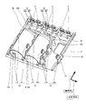
- FIG. 1 is an exploded perspective view showing a state before assembly of a bus bar unit and a terminal guide in an electronic control device according to an embodiment of the present invention.
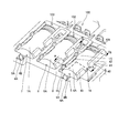
- FIG. 2 is a perspective view showing a state where an electrolytic capacitor is attached to the clip portion of the electronic component holder according to the embodiment of the present invention.
- FIG. 3 is a perspective view showing a clip portion and a restriction portion in the electronic component holder according to the embodiment of the present invention.
- 4 is a cross-sectional view taken along the line AA in FIG.
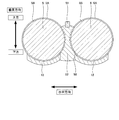
- FIG. 7 is a cross-sectional view illustrating an assembly procedure of the electronic component holder according to the embodiment of the present invention, and is a diagram illustrating a process of attaching the electrolytic capacitor to the clip portion.
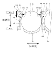
- FIG. 8 is a cross-sectional view illustrating the procedure for assembling the electronic component holder according to the embodiment of the present invention, and is a diagram illustrating a process of locking the restricting portion to the clip portion.
- the electronic component holder 100 is used in an electronic control device 10 including a pair of electronic substrates.
- the electronic control device 10 includes a power supply substrate 1 as an electronic substrate that controls power supplied to a control object (not shown), and an electronic device that transmits and receives control signals to control the control object. And a control board (not shown) as a board.
- the electronic component holder 100 holds a cylindrical electronic component mounted on the bus bar unit 2 attached to the power supply substrate 1.
- the electronic control device 10 is, for example, an ECU (Engine Control Unit) that controls a vehicle engine as a control object, or an ECU (Electronic Control Unit: electronic control) that controls an electric power steering device as a control object. Device).
- ECU Engine Control Unit
- ECU Electronic Control Unit: electronic control
- the power supply substrate 1 is a flat printed board formed of a metal having high heat dissipation such as aluminum.
- the power supply substrate 1 is formed in a substantially rectangular shape, and an electronic circuit is formed on its surface 1A.
- a bus bar unit 2 on which electronic components are mounted is attached to the power supply board.
- the bus bar unit 2 electrically connects the power supply substrate 1 and the control substrate.
- the bus bar unit 2 includes a plurality of terminals (bus bars) 3 and a covering portion 4 that holds the terminals 3 together on the power supply substrate 1.
- the covering portion 4 is formed by molding a plurality of terminals 3 with a resin material.
- the resin material is an insulating material that insulates the plurality of terminals 3 from each other.
- FIG. 1 only the terminals 3 to which leads 8 of electrolytic capacitors 5, 6 and 7 described later are connected are shown, and the other terminals are not shown.
- electrolytic capacitors 5, 6, and 7 are mounted on the surface of the bus bar unit 2, electrolytic capacitors 5, 6, and 7 as cylindrical electronic components that remove noise and adjust the voltage to be constant, and other electronic components (not shown) are mounted.
- three electrolytic capacitors 5, 6, and 7 are mounted on the bus bar unit 2 so that the central axes are arranged substantially parallel to each other.
- the electrolytic capacitors 5, 6, and 7 are provided so that the central axis is substantially parallel to the surface of the bus bar unit 2 without being inclined.
- the electrolytic capacitors 5, 6 and 7 are provided with a pair of leads 8 protruding from one end face.
- the pair of leads 8 extends from one end face of the electrolytic capacitors 5, 6, and 7 in the central axis direction (extends substantially parallel to the central axis), and is bent from the parallel part 8 A and extends in a direction perpendicular to the central axis. And a vertical portion 8B.
- Each of the pair of leads 8 has a vertical portion 8B electrically connected to the terminal 3.
- recessed portions 5B, 6B, and 7B that are formed in an annular shape are formed (see FIGS. 2 and 6). In FIG.
- the electrolytic capacitor 5 is omitted, and only the electrolytic capacitors 6 and 7 are illustrated.
- the recessed portions 5B, 6B, and 7B are not limited to an annular shape, and may be formed in a part of the outer peripheral surfaces 5A, 6A, and 7A in the circumferential direction.
- a terminal guide 9 shown in FIG. 1 is attached to the bus bar unit 2.
- the bus bar unit 2 and the terminal guide 9 are fixed while being removed from each other by a hook portion 4 ⁇ / b> A as a fixing portion provided in the bus bar unit 2.
- the hook portion 4A is provided at a position facing the bottom surfaces of the electrolytic capacitor 5 and the electrolytic capacitor 7 held by the bus bar unit 2, and is inserted through a hook hole 9A formed at a corresponding position of the terminal guide 9. To do.
- the hook claw 4B at the tip of the hook portion 4A is engaged with the terminal guide 9, and the bus bar unit 2 and the terminal guide 9 are prevented from being removed due to disturbance such as vibration, and both are fixed. .
- the terminal guide 9 is provided between the power supply board 1 and the control board, and the position of the terminal is guide holes (not shown) so that a terminal (not shown) can be connected to the control board when attached to the bus bar unit 2. (Omitted).
- the terminal guide 9 is a substantially flat resin member whose front surface faces the control board and whose back surface faces the bus bar unit 2.
- the electronic component holder 100 holds the three electrolytic capacitors 5, 6, 7 mounted on the bus bar unit 2, and fixes the electrolytic capacitors 5, 6, 7 to the bus bar unit 2.
- the configuration of the electronic component holder 100 will be described in detail with reference to FIGS. 1 to 6.
- the direction in which the central axes of the electrolytic capacitors 5, 6, 7 extend is “axial direction”, and the direction in which the electrolytic capacitors 5, 6, 7 are aligned is “horizontal direction”.
- the direction perpendicular to the surface 1A of the power supply substrate 1 will be described as “vertical direction”.
- the axial direction, the horizontal direction, and the vertical direction are directions along three orthogonal axes that are orthogonal to each other.
- the bus bar unit 2 side is defined as “downward” and the terminal guide 9 side is defined as “upward”.
- the electronic component holder 100 has first, second, and third holder portions 101, 102, and 103 for holding three electrolytic capacitors 5, 6, and 7, respectively, as shown in FIG.
- the first, second, and third holder portions 101, 102, and 103 have the same configuration. Therefore, below, the structure of the 1st holder part 101 is mainly demonstrated, and description is abbreviate
- the first holder part 101 is also simply referred to as “holder part 101”.
- the holder portion 101 is provided on the bus bar unit 2 and is formed so as to be expandable / contractable.
- the holder portion 101 accommodates the electrolytic capacitor 5 and sandwiches the outer peripheral surface 5 ⁇ / b> A of the electrolytic capacitor 5.
- a restriction portion 30 provided on the guide 9 and locked to the clip portion 11 to restrict the separation of the clip portion 11 from the outer peripheral surface 5A of the electrolytic capacitor 5 and a terminal guide 9 provided on the terminal guide 9 to the bus bar unit 2
- a contact portion 40 that contacts the outer peripheral surface 5A of the electrolytic capacitor 5 from the vertical direction that is the attaching / detaching direction.
- the bus bar unit 2 corresponds to the first member
- the terminal guide 9 corresponds to the second member.
- the clip portion 11 is integrally formed with a covering portion 4 that is molded into a plurality of terminals 3. That is, the clip part 11 is formed of a resin material that constitutes the covering part 4. As shown in FIGS. 2 and 4, the clip portion 11 includes a support portion 12 that supports the electrolytic capacitor 5 and a plurality of claw portions 13 that are formed to extend in the circumferential direction of the electrolytic capacitor 5.
- the support portion 12 is formed so as to cover a part of the outer peripheral surface 5A on the lower side in the vertical direction of the electrolytic capacitor 5, as shown in FIG. That is, the support portion 12 contacts a part of the outer peripheral surface 5A of the electrolytic capacitor 5 that is vertically lower than the central axis.
- the plurality of claw portions 13 are provided on both sides in the horizontal direction across the central axis of the electrolytic capacitor 5, and sandwich the electrolytic capacitor 5.
- the plurality of claw portions 13 include a single first claw portion 14 provided on one side of the electrolytic capacitor 5 across the central axis, and two second claw portions 15 provided on the other side. And having.
- the first claw portion 14 and the second claw portion 15 are provided to alternately face each other with the electrolytic capacitor 5 interposed therebetween.
- the two second claw portions 15 are provided apart in the axial direction.
- the first claw portion 14 is provided such that the position in the axial direction is between the two second claw portions 15.
- the first claw portions 14 that are in contact with the three electrolytic capacitors 5, 6, and 7 are provided so that their axial positions substantially coincide with each other.
- the 2nd claw part 15 which contacts each of three electrolytic capacitors 5, 6, and 7 is also provided so that an axial direction position may mutually correspond substantially. That is, the first claw portion 14 of the second holder 102 is arranged between the two second claw portions 15 of the first holder 101 in the axial direction.
- the distance between the adjacent electrolytic capacitors 5, 6, 7 can be changed between the first claw part 14 and the second claw part 15. It is sufficient if it can secure a thickness of one, and space can be saved. Further, by arranging the first claw portions 14 and the second claw portions 15 alternately, the electrolytic capacitors 5, 6 and 7 can be held over the entire length in the axial direction by a small number of claw portions 13. In addition, the 1st nail
- the first claw portion 14 and the second claw portion 15 are formed from the covering portion 4 and have arm portions having contact portions 14 ⁇ / b> A and 15 ⁇ / b> A that are in contact with the cylindrical outer peripheral surface 5 ⁇ / b> A of the electrolytic capacitor 5.
- 14B, 15B and projections 14C, 15C that are formed from the contact portions 14A, 15A and are spaced apart from the outer peripheral surface 5A of the electrolytic capacitor 5 and serve as free ends of the first claw portion 14 and the second claw portion 15, respectively.
- arm part 14B, 15B is a base end side connected to the coating
- the contact portions 14A and 15A correspond to boundary portions between the arm portions 14B and 15B and the projection portions 14C and 15C.
- the arm portions 14B and 15B are formed so as to extend in the circumferential direction of the electrolytic capacitor 5 over the vertical direction from the central axis of the electrolytic capacitor 5, and their end portions (boundary portions with the projecting portions 14C and 15C) are contact portions 14A.
- 15A is in contact with the electrolytic capacitor 5. That is, the contact portions 14 ⁇ / b> A and 15 ⁇ / b> A are in contact with the outer peripheral surface 5 ⁇ / b> A of the electrolytic capacitor 5 above the central axis of the electrolytic capacitor 5 in the vertical direction.
- the electrolytic capacitor 5 is formed by the contact portions 14A and 15A of the first and second claw portions 14 and 15 that are in contact with each other in the vertical direction above the center axis and the support portion 12 that is in contact in the lower direction in the vertical direction than the center axis. , Sandwiched from the radial direction.
- the projecting portions 14C and 15C are formed to extend upward from the contact portions 14A and 15A of the arm portions 14B and 15B so as to be separated from the electrolytic capacitor 5 in the vertical direction.
- the horizontal interval between the protrusion 14 ⁇ / b> C of the first claw part 14 and the protrusion 15 ⁇ / b> C of the second claw part 15 is smaller than the diameter of the electrolytic capacitor 5.
- the plurality of claw portions 13 have a horizontal space between the projection portion 14C of the first claw portion 14 and the projection portion 15C of the second claw portion 15, and the base portions of the arm portions 14B and 15B are rooted. It is formed to be able to expand and contract so as to bend from
- the restricting portion 30 includes a first restricting portion 31 that contacts the first claw portion 14 and a second restricting portion 32 that contacts the second claw portion 15.
- the first restricting portion 31 and the second restricting portion 32 are provided in a non-contact manner apart from the arm portions 14 ⁇ / b> B and 15 ⁇ / b> B of the first claw portion 14 and the second claw portion 15, respectively.
- the first restricting portion 31 and the second restricting portion 32 have tapered portions 31A and 32A that are directed outward in the horizontal direction from the central axis of the electrolytic capacitor 5 as approaching the bus bar unit 2 that is the lower portion in FIG. That is, the restricting portion 30 is formed such that the horizontal interval between the first restricting portion 31 and the second restricting portion 32 increases as it goes from the upper side to the lower side in the vertical direction toward the bus bar unit 2.
- the restricting portion 32 contacts the protrusions 14C and 15C at positions spaced vertically upward from the contact portions 14A and 15A of the first claw portion 14 and the second claw portion 15, respectively.
- the protrusions 14 ⁇ / b> C and 15 ⁇ / b> C are pressed toward the central axis of the electrolytic capacitor 5 by the first restricting portion 31 and the second restricting portion 32.
- the expansion of the first claw part 14 and the second claw part 15 moving from the central axis of the electrolytic capacitor 5 toward the outside in the horizontal direction (expansion / contraction direction) is restricted by the restriction part 30.
- first restricting portion 31 and the second restricting portion 32 are projected portions 14C and 15C toward the central axis of the electrolytic capacitor 5 with the contact portions 14A and 15A of the first claw portion 14 and the second claw portion 15 as fulcrums, respectively. Therefore, the moment arm length L (see FIG. 4) of the force that regulates the separation between the contact portions 14A and 15A and the electrolytic capacitor 5 can be made longer. Therefore, the contact of the first claw part 14 and the second claw part 15 to the outer peripheral surface 5A of the electrolytic capacitor 5 is maintained, and the clamping by the clip part 11 is more reliably prevented from being released due to vibration or the like. Thus, the electrolytic capacitor 5 can be securely fixed.
- the contact portion 40 includes two first contact portions 41 provided on one side in the horizontal direction of the electrolytic capacitor 5 and a single contact provided on the other side in the horizontal direction of the electrolytic capacitor 5. Second abutting portion 42.
- the first contact portion 41 is provided so as to sandwich the first claw portion 14 in the axial direction.
- the second contact portion 42 is provided so that the axial position is between the second claw portions 15. That is, the 1st nail
- the electronic component holder 100 includes a locking hole 50 formed in the covering portion 4 of the power supply substrate 1, a facing portion 51 provided facing the locking hole 50, A locking portion 52 (see FIG. 6) that is locked across the recessed portions 5B and 6B of the capacitors 5 and 6 and the locking hole 50 is further provided.
- the locking hole 50 is between the horizontal directions of the adjacent electrolytic capacitors 5 and 6, and the position in the axial direction substantially coincides with the recessed portions 5 ⁇ / b> B and 6 ⁇ / b> B of the electrolytic capacitors 5 and 6. Formed. That is, the locking hole 50 is provided to face the recessed portions 5B and 6B of the adjacent electrolytic capacitors 5 and 6, respectively.
- the locking hole 50 does not have to be provided at a position where the axial positions substantially coincide with the recessed portions 5B and 6B of the electrolytic capacitors 5 and 6, and any locking holes 52 that will be described later can be formed. Can be provided in position.
- the facing portion 51 is provided between the adjacent electrolytic capacitors 5 and 6.
- the opposing portion 51 is formed in a substantially U shape whose both ends are connected to the covering portion 4 on both sides in the axial direction across the locking hole 50 and whose central portion faces the locking hole 50.
- the locking portion 52 is formed of a thermoplastic material (for example, a hot melt resin such as polyamide or polypropylene) that has fluidity and cures with a decrease in temperature over time. As shown in FIG. 6, the locking portion 52 is locked to the locking hole 50 and the facing portion 51 and is filled in a part of the recessed portions 5 ⁇ / b> B and 6 ⁇ / b> B of the electrolytic capacitors 5 and 6. The locking portion 52 is filled and locked in the recess portions 5B and 6B, thereby holding the electrolytic capacitors 5 and 6 and restricting movement in the axial direction.
- a thermoplastic material for example, a hot melt resin such as polyamide or polypropylene
- the locking portion 52 is provided so as to cover the outer peripheral surfaces 5A and 6A of the electrolytic capacitors 5 and 6 so as to straddle the central axis of the electrolytic capacitors 5 and 6 in the vertical direction. Thereby, the latching
- the electrolytic capacitor 5 is attached to the clip portion 11 provided in the bus bar unit 2. Specifically, as shown in FIG. 7, the first claw portion 14 and the second claw portion 15 are passed through the opening 13A formed by the protrusions 14C and 15C in the first claw portion 14 and the second claw portion 15. The electrolytic capacitor 5 is inserted while being expanded and accommodated inside the first claw portion 14 and the second claw portion 15. In this state, the contact portions 14A and 15A of the arm portions 14B and 15B in the first claw portion 14 and the second claw portion 15 do not contact the outer peripheral surface 5A of the electrolytic capacitor 5 and are provided with a slight gap. .
- the terminal guide 9 is assembled to the bus bar unit 2. Specifically, the terminal guide is provided such that the hook portion 4A provided in the bus bar unit 2 is inserted into the hook hole 9A formed in the terminal guide 9, and the hook claw 4B at the tip of the hook portion 4A is engaged with the terminal guide 9. 9 is moved downward from the upper part in the vertical direction.
- the plurality of claw portions 13 are inserted inside the restricting portion 30. More specifically, as shown in FIG. 8, when the terminal guide 9 is lowered, the projections 14 ⁇ / b> C and 15 ⁇ / b> C of the first claw portion 14 and the second claw portion 15 correspond to the corresponding first regulating portions 31.
- the first restricting portion 31 and the second restricting portion 32 are pressed toward the central axis of the electrolytic capacitor 5 while being guided by the tapered portions 31A and 32A of the second restricting portion 32.
- the first restricting portion 31 and the second restricting portion 32 are protruded inwardly toward the central axis of the electrolytic capacitor 5 with the contact portions 14A and 15A serving as fulcrums. Press 15C.
- the arm portions 14B and 15B are deformed from the root (base end side) and swelled radially outward as indicated by arrows in FIG. In this way, the clip portion 11 contracts, and the claw portion 13 and the restricting portion 30 are locked (state shown in FIG. 4).
- the deformed arm portions 14B and 15B are configured not to contact the tapered portions 31A and 32A of the restricting portion 30.
- the terminal guide 9 can be securely attached to the bus bar unit 2.
- the electrolytic capacitor 5 is sandwiched by the clip portion 11, and the separation of the clip portion 11 is prevented by the restricting portion 30, and the sandwiching of the electrolytic capacitor 5 by the clip portion 11 is maintained. Therefore, the electrolytic capacitor 5 is more securely fixed to the bus bar unit 2 by the electronic component holder 100.
- the bus bar unit 2 and the terminal guide 9 are prevented from being removed from each other by the hook portion 4A.
- the hook portion 4 ⁇ / b> A is desirably provided at a position adjacent to the electrolytic capacitors 5, 6, 7, that is, around the electrolytic capacitors 5, 6, 7. According to this, the bus bar unit 2 and the terminal guide 9 are removed due to disturbance such as vibration, and the locking of the restricting portion 30 and the clip portion 11 is released, so that the separation of the clip portion 11 cannot be prevented, and the electrolytic capacitor 5 , 6 and 7 can be effectively prevented.
- the contact portions 14A, 15A and the outer peripheral surface 5A of the electrolytic capacitor 5 are not in contact with each other (see FIG. 7), and accompanying the attachment of the terminal guide 9 to the bus bar unit 2
- the first restricting portion 31 and the second restricting portion 32 press the projections 14C and 15C, so that the contact portions 14A and 15A and the outer peripheral surface 5A of the electrolytic capacitor 5 come into contact (see FIG. 8). That is, the horizontal interval between the protrusions 14C and 15C of the first claw part 14 and the second claw part 15 in the state where the protrusions 14C and 15C are in contact with the first restriction part 31 and the second restriction part 32 is the protrusion.
- the contact portion 40 provided on the terminal guide 9 contacts the outer peripheral surface 5A of the electrolytic capacitor 5 from above in the vertical direction. Therefore, in addition to the holding of the electrolytic capacitor 5 by the clip portion 11 and the regulating portion 30, the electrolytic capacitor 5 is also held in the radial direction by the support portion 12 and the contact portion 40. Thereby, the electrolytic capacitor 5 is more reliably fixed to the bus bar unit 2.
- thermoplastic material is applied toward the electrolytic capacitor 5 through the locking holes 50 to form the locking portions 52.
- the assembly of the bus bar unit 2 and the terminal guide 9 is inverted so that the vertical direction is reversed, and the facing portion 51 is positioned below the locking hole 50 in the vertical direction.
- a thermoplastic material is injected from the locking hole 50.
- the injected thermoplastic material is prevented from falling downward by the facing portion 51 and flows into the recessed portions 5B and 6B of the electrolytic capacitors 5 and 6.
- the hollow portions 5B and 6B are filled with the thermoplastic material.
- the thermoplastic material is filled so as to fill the locking holes 50.
- thermoplastic material applied to the electrolytic capacitor 5 is cured with a decrease in fluidity as the temperature decreases with time.
- a locking portion 52 that is locked across the recess portions 5 ⁇ / b> B and 6 ⁇ / b> B of the electrolytic capacitors 5 and 6 and the locking hole 50 is formed.
- the assembly of the bus bar unit 2 and the terminal guide 9 is reversed again and attached to the power supply substrate 1. Further, the control board is lowered from above with respect to the assembly of the power supply board 1, the bus bar unit 2, and the terminal guide 9, and is pushed so as to be seated on the terminal guide 9.
- the assembly of the power supply board 1, the bus bar unit 2, the terminal guide 9, and the control board is attached to the inside of the housing (not shown), and the assembly of the electronic control device 10 is completed.
- the electrolytic capacitor 5 may vibrate using the fixed lead 8 as a fulcrum.
- the electronic control device 10 is mounted on a vehicle that is susceptible to vibration, such as when an object to be controlled is an engine or an electric power steering device, the risk of vibration of the electrolytic capacitor 5 becomes greater. . Due to the vibration of the electrolytic capacitor 5, the lead 8 may be bent and the durability of the lead 8 may be reduced.
- the outer peripheral surface 5A of the electrolytic capacitor 5 is mechanically fixed to the bus bar unit 2 by the electronic component holder 100. For this reason, even if it is a case where the outer peripheral surface 5A of the electrolytic capacitor 5 has poor adhesiveness and it is difficult to fix it with an adhesive, the electrolytic capacitor 5 can be fixed more reliably.
- the clip portion 11 clamps the electrolytic capacitor 5 from the radial direction, the force for regulating the vibration in the axial direction is smaller than the force for regulating the vibration in the horizontal direction and the vertical direction.
- the electronic component holder 100 has a locking portion 52 that is locked over the locking hole 50, in other words, the covering portion 4 of the bus bar unit 2 and the recessed portions 5B, 6B of the electrolytic capacitors 5, 6.
- the locking portion 52 restricts the movement of the electrolytic capacitor 5 in the axial direction. Therefore, the movement of the electrolytic capacitor 5 in the axial direction can be more reliably regulated, and the electrolytic capacitor 5 can be more reliably fixed. If the clip portion 11 can sufficiently restrict the movement of the electrolytic capacitor 5 in the axial direction, the locking portion 52 may not be provided. That is, the electronic component holder 100 does not necessarily include the locking portion 52.
- the locking portion 52 is locked to the recess portions 5B and 6B of the electrolytic capacitors 5 and 6, whereby the movement of the electrolytic capacitor 5 in the axial direction is restricted.
- the vertical portion 8B of the lead 8 in the electrolytic capacitor 5 and the terminal 3 extending vertically are connected, it is necessary to align the vertical portion 8B and the terminal 3 so as to eliminate the distance in the axial direction for welding.
- the positions of the recesses 5B and 6B in the axial direction are likely to vary. In such a case, since the engaging portion 52 is formed of a thermoplastic material having fluidity, alignment is not necessary, and therefore, the engaging portion 52 is formed after welding the lead 8 and the terminal 3.
- the locking portion 52 is filled in the recessed portions 5B and 6B of the electrolytic capacitors 5 and 6, and is formed over the vertical direction so as to straddle the central axis in the vertical direction.
- the locking portion 52 may be formed only vertically below the central axis. In this case, the movement of the electrolytic capacitor 5 in the vertical direction cannot be restricted by the locking portion 52, but the movement of the electrolytic capacitor 5 in the axial direction can be restricted.
- claw part 15, and the electrolytic capacitor 5 may be in contact with each other.
- the outer diameter of the electrolytic capacitor 5 may vary due to tolerances, etc., but the contact portions 14A and 15A and the outer peripheral surface 5A of the electrolytic capacitor 5 are in a state where the claw portion 13 and the regulating portion 30 are not locked. They may be in contact with each other or may be non-contact.
- the first restricting portion 31 and the second restricting portion 32 press the protruding portions 14C and 15C, and the contact portions 14A and 15A.
- the outer peripheral surface 5A of the electrolytic capacitor 5 may be in contact with each other.
- the electronic component holder 100 holds the electrolytic capacitor 5 as a cylindrical electronic component.
- the electronic component holder 100 may hold an electronic component such as a choke coil formed by winding a wire around a cylindrical shaft portion, for example.
- the clip portion 11 is integrally formed with the covering portion 4 of the bus bar unit 2, and the restricting portion 30 is integrally formed with the terminal guide 9. That is, in the above embodiment, a part of the covering portion 4 and the terminal guide 9 constitutes the electronic component holder 100.
- the electronic component holder 100 is configured as a separate member from the first member provided with the clip portion 11 and configured separately from the bus bar unit 2 and the terminal guide 9 provided as the regulating portion 3. And a second member. In this case, the first member may be attached to the bus bar unit 2 and the second member may be attached to the terminal guide 9.
- the clip portion 11 holds the electrolytic capacitor 5 and the restricting portion 30 prevents the electrolytic capacitor 5 and the clip portion 11 from being separated from each other, regardless of the adhesiveness of the outer peripheral surface 5A of the electrolytic capacitor 5.
- the electrolytic capacitor 5 can be fixed to the bus bar unit 2. Therefore, the electrolytic capacitor 5 provided in the electronic control device 10 is more reliably fixed.
- the contact portions 14 ⁇ / b> A and 15 ⁇ / b> A and the outer peripheral surface 5 ⁇ / b> A of the electrolytic capacitor 5 are not in contact with each other, and the restricting portion 30 is attached along with the attachment of the terminal guide 9 to the power supply substrate 1.
- the contact portions 14A and 15A press the outer peripheral surface 5A of the electrolytic capacitor 5.
- the electronic component holder 100 since the electronic component holder 100 has a locking portion 52 that is locked across the locking hole 50 and the recess portions 5B and 6B of the electrolytic capacitors 5 and 6, the electronic component holder 100 is moved in the axial direction of the electrolytic capacitor 5 by the locking portion 52. Movement is restricted. Therefore, the movement of the electrolytic capacitor 5 in the axial direction can be more reliably regulated, and the electrolytic capacitor 5 can be more reliably fixed.
- the electronic component holder 100 for holding the cylindrical electrolytic capacitors 5, 6, 7 provided in the electronic control device 10 is formed so as to be expandable / contractable and accommodates the electrolytic capacitors 5, 6, 7.
- Clip part 11 that holds outer peripheral surfaces 5A, 6A, and 7A, and a restricting part that engages with clip part 11 and restricts the separation of clip part 11 from outer peripheral surfaces 5A, 6A, and 7A of electrolytic capacitors 5, 6, and 7 30.
- the clip portion 11 sandwiches the electrolytic capacitors 5, 6, and 7, and the restricting portion 30 prevents the electrolytic capacitors 5, 6, and 7 from being separated from the clip portion 11.
- the main body portions of the electrolytic capacitors 5, 6, and 7 can be fixed. Therefore, the electrolytic capacitors 5, 6, and 7 provided in the electronic control device are more reliably fixed.
- the clip portion 11 has a plurality of claw portions 13 provided on both sides of the center axis of the electrolytic capacitors 5, 6, and 7, and the claw portion 13 is formed of the electrolytic capacitors 5, 6, and 7.
- Arm portions 14B and 15B formed with contact portions 14A and 15A that contact the outer peripheral surfaces 5A, 6A, and 7A, and outer peripheral surfaces 5A, 6A of the electrolytic capacitors 5, 6, and 7 formed from the contact portions 14A and 15A.
- the restricting portion 30 presses the projecting portions 14C and 15C in the horizontal direction in which the clip portion 11 is contracted.
- the protrusions 14C and 15C are pressed toward the central axis by the restricting portion 30, so that the contact portions 14A and 15A can be securely connected.
- the outer peripheral surfaces 5A, 6A, and 7A of the electrolytic capacitors 5, 6, and 7 can be brought into contact with each other. Therefore, the electrolytic capacitors 5, 6, and 7 can be more reliably fixed.
- the first restricting portion 31 and the second restricting portion 32 press the protruding portions 14C and 15C using the contact portions 14A and 15A as fulcrums.
- the moment arm length L of the force that regulates the separation between the contact portions 14A, 15A and the electrolytic capacitors 5, 6, 7 by the first restricting portion 31 and the second restricting portion 32 can be made longer. Therefore, it is possible to more reliably prevent the clip portion 11 from releasing.
- the electronic component holder 100 holds three electrolytic capacitors 5, 6, 7 whose central axes are arranged in parallel with each other, and the plurality of claw portions 13 are sandwiched between the central axes of the electrolytic capacitors 5, 6, 7.
- the first claw portion 14 provided on the side and the second claw portion 15 provided on the other side are provided, and the first claw portion 14 and the second claw portion 15 are arranged so as to be shifted from each other in the central axis direction.
- the interval between the adjacent electrolytic capacitors 5, 6 and 7 can be set to a thickness corresponding to one of the first claw part 14 and the second claw part 15. Therefore, the space for the electronic component holder 100 can be saved.
- the electronic component holder 100 further includes a bus bar unit 2 and a terminal guide 9 that are configured to be detachable from each other, a clip portion 11 is provided in the bus bar unit 2, and a restriction portion 30 is provided in the electronic component holder 100.
- the electronic component holder 100 further includes a contact portion 40 that is provided in the terminal guide 9 together with the restricting portion 30 and that contacts the electrolytic capacitors 5, 6, 7 in a state where the bus bar unit 2 and the terminal guide 9 are mounted.
- the contact portion 40 contacts the electrolytic capacitors 5, 6, 7, thereby preventing the electrolytic capacitor 5 from moving in the attaching / detaching direction and fixing the electrolytic capacitors 5, 6, 7 more reliably. it can.
- the first member is the bus bar unit 2 in which the terminal 3 is covered by the covering portion 4 formed of a resin material, and the clip portion 11 is integrally formed with the covering portion 4 by the resin material.
- the cover portion 4 is integrally formed, the clip portion 11 can be easily formed, and the manufacturing cost is reduced.
- the electronic component holder 100 further includes a hook portion 4A that engages the bus bar unit 2 and the terminal guide 9 to restrict the removal of both.
- the contact portions 14A and 15A in the claw portion 13 are in contact with the recess portions 5B, 6B, and 7B formed on the outer peripheral surfaces 5A, 6A, and 7A of the electrolytic capacitors 5, 6, and 7, respectively.
- the electronic component holder 100 includes a locking hole 50 provided in the covering portion 4 of the bus bar unit 2 and depressions 5B, 6B, and 7B formed in the outer peripheral surfaces 5A, 6A, and 7A of the electrolytic capacitors 5, 6, and 7. And a locking portion 52 that is locked over the locking hole 50 and positions the electrolytic capacitors 5, 6, and 7 in the axial direction with respect to the bus bar unit 2.
- the electrolytic capacitors 5, 6, 7 are positioned in the axial direction by the locking portion 52. Therefore, the electrolytic capacitors 5, 6, and 7 can be more reliably fixed.
Landscapes
- Engineering & Computer Science (AREA)
- Power Engineering (AREA)
- Microelectronics & Electronic Packaging (AREA)
- Mounting Components In General For Electric Apparatus (AREA)
- Power Conversion In General (AREA)
- Structures For Mounting Electric Components On Printed Circuit Boards (AREA)
Abstract
電子制御装置10に設けられる円筒状の電解コンデンサ5を保持する電子部品ホルダ100は、拡縮可能に形成され電解コンデンサ5を収容して電解コンデンサ5の外周面5Aを挟持するクリップ部11と、クリップ部11に係止して電解コンデンサ5の外周面5Aからのクリップ部11の離間を規制する規制部30と、を備える。
Description
本発明は、電子部品ホルダに関するものである。
従来から、電子制御装置には、円筒状の電子部品が実装される。JP2010-35304Aには、端子に接続される円筒状のコンデンサが電子回路基板に実装される構成が開示されている。
電子制御装置に実装される円筒状の電子部品には、外周面が接着剤によって接着されにくい難接着性を有するものがある。このような電子部品を固定する方法として、例えば、電子部品の接続端子に接着剤を塗布して、電子部品を固定するものがある。
しかしながら、接続端子を固定する方法では、電子部品の本体部分は拘束されていないため、振動等が入力されると固定された接続端子を支点として本体部分が振動するおそれがある。このような電子部品本体の振動により、接続端子に曲げが生じて接続端子の耐久性が低下するおそれがある。
本発明は、電子制御装置に設けられる電子部品をより確実に固定することを目的とする。
本発明のある態様によれば、電子制御装置に設けられる円筒状の電子部品を保持する電子部品ホルダであって、拡縮可能に形成され電子部品を収容して電子部品の外周面を挟持するクリップ部と、クリップ部に係止して外周面からのクリップ部の離間を規制する規制部と、を備える。
以下、図面を参照して、本発明の実施形態に係る電子部品ホルダ100ついて説明する。
電子部品ホルダ100は、一対の電子基板を備える電子制御装置10に用いられる。電子制御装置10は、図1に示すように、制御対象物(図示省略)に供給する電源を制御する電子基板としての電源用基板1と、制御信号を送受信して制御対象物を制御する電子基板としての制御用基板(図示省略)と、を備える。電子部品ホルダ100は、電源用基板1に取り付けられるバスバーユニット2に実装される円筒状の電子部品を保持する。
電子制御装置10は、例えば、制御対象物として車両のエンジンを制御するECU(Engine Control Unit:エンジン用制御装置)や、制御対象物として電動パワーステアリング装置を制御するECU(Electronic Control Unit:電子制御装置)などである。
電源用基板1は、アルミニウムなど放熱性の高い金属によって形成される平板状のプリント基板である。電源用基板1は、略矩形に形成され、その表面1Aに電子回路が形成される。電源基板には、電子部品が実装されるバスバーユニット2が取り付けられる。バスバーユニット2は、電源用基板1と制御用基板とを電気的に接続する。
バスバーユニット2は、図1に示すように、複数の端子(バスバー)3と、複数の端子3をまとめて電源用基板1に保持する被覆部4と、を有する。被覆部4は、樹脂材によって複数の端子3をモールド成形することにより形成される。樹脂材は、複数の端子3を互いに絶縁する絶縁材料である。なお、説明の便宜上、図1においては、後述する電解コンデンサ5,6,7のリード8が接続される端子3のみを図示し、その他の端子の図示を省略する。
バスバーユニット2の表面には、ノイズを除去して電圧を一定に調整する円筒状の電子部品としての電解コンデンサ5,6,7と、その他の電子部品(図示省略)と、が実装される。
電子制御装置10では、中心軸が互いに略平行に並ぶように3つの電解コンデンサ5,6,7がバスバーユニット2に実装される。電解コンデンサ5,6,7は、バスバーユニット2の表面に対して、中心軸が傾斜せずに略平行となるように設けられる。
電解コンデンサ5,6,7には、図2に示すように、一端面から突出する一対のリード8が設けられる。一対のリード8は、電解コンデンサ5,6,7の一端面から中心軸方向に延びる(中心軸と略平行に延びる)平行部8Aと、平行部8Aから折れ曲がって中心軸に垂直な方向へ延びる垂直部8Bと、をそれぞれ有する。一対のリード8は、それぞれ垂直部8Bが端子3に電気的に接続される。また、電解コンデンサ5,6,7の外周面5A,6A,7Aには、環状に窪んで形成される窪み部5B,6B,7Bが形成される(図2及び図6参照)。なお、図2では、電解コンデンサ5の図示を省略し、電解コンデンサ6,7のみを図示している。また、窪み部5B,6B,7Bは、環状に限らず、外周面5A,6A,7Aの周方向の一部に形成されるものでもよい。
バスバーユニット2には、図1に示す端子ガイド9が取り付けられる。バスバーユニット2と端子ガイド9とは、バスバーユニット2に設けられる固定部としてのフック部4Aによって互いの取り外しが規制されて固定される。具体的には、フック部4Aは、バスバーユニット2に保持される電解コンデンサ5及び電解コンデンサ7の底面に対向する位置に設けられ、端子ガイド9の対応する位置に形成されるフック孔9Aを挿通する。これにより、フック部4Aの先端のフック爪4Bが端子ガイド9に係合し、バスバーユニット2と端子ガイド9とが振動等の外乱に起因して取り外されることが防止され、両者が固定される。
端子ガイド9は、電源用基板1と制御用基板との間に設けられ、バスバーユニット2に取り付けられた状態で図示しない端子を制御用基板に接続可能なように端子の位置をガイド孔(図示省略)によって規定する。端子ガイド9は、表面が制御用基板に臨み、裏面がバスバーユニット2に臨む略平板状の樹脂部材である。
電子部品ホルダ100は、バスバーユニット2に実装される3つの電解コンデンサ5,6,7をそれぞれ保持して、電解コンデンサ5,6,7をバスバーユニット2に対して固定する。以下、図1から図6を参照して、電子部品ホルダ100の構成について詳しく説明する。なお、以下では、説明の便宜上、図1に示すように、電解コンデンサ5,6,7の中心軸が伸びる方向を「軸方向」、電解コンデンサ5,6,7が並ぶ方向を「水平方向」、電源用基板1の表面1Aに対して垂直な方向を「垂直方向」として説明する。軸方向、水平方向、及び垂直方向は、互いに直交する直交3軸に沿った方向である。また、垂直方向において、図1に示すように、バスバーユニット2側を「下方」、端子ガイド9側を「上方」とする。
電子部品ホルダ100は、図3に示すように、3つの電解コンデンサ5,6,7をそれぞれ保持する第1,第2,第3ホルダ部101,102,103を有する。第1,第2,第3ホルダ部101,102,103は、互いに同様の構成を有する。したがって、以下では、主に第1ホルダ部101の構成について説明し、第2,第3ホルダ部102,103の構成については、適宜説明を省略する。また、以下では、第1ホルダ部101を単に「ホルダ部101」とも称する。
ホルダ部101は、図2から図4に示すように、バスバーユニット2に設けられると共に拡縮可能に形成され電解コンデンサ5を収容して電解コンデンサ5の外周面5Aを挟持するクリップ部11と、端子ガイド9に設けられると共にクリップ部11に係止して電解コンデンサ5の外周面5Aからのクリップ部11の離間を規制する規制部30と、端子ガイド9に設けられバスバーユニット2への端子ガイド9の着脱方向である垂直方向から電解コンデンサ5の外周面5Aに当接する当接部40と、を有する。本実施形態では、バスバーユニット2が第1部材に相当し、端子ガイド9が第2部材に相当する。
クリップ部11は、図2に示すように、複数の端子3にモールド成形される被覆部4と共に一体形成される。つまり、クリップ部11は、被覆部4を構成する樹脂材によって形成される。クリップ部11は、図2及び図4に示すように、電解コンデンサ5を支持する支持部12と、電解コンデンサ5の周方向に延びて形成される複数の爪部13と、を有する。
支持部12は、図4に示すように、電解コンデンサ5の垂直方向下方側の外周面5Aの一部を覆うように形成される。つまり、支持部12は、中心軸よりも垂直方向下方にある電解コンデンサ5の外周面5Aの一部に接触する。
複数の爪部13は、図2に示すように、電解コンデンサ5の中心軸を挟んで水平方向の両側に設けられ、電解コンデンサ5を挟持する。具体的には、複数の爪部13は、電解コンデンサ5に対して中心軸を挟んで一方側に設けられる単一の第1爪部14と、他方側に設けられる2つの第2爪部15と、を有する。
第1爪部14と第2爪部15とは、電解コンデンサ5を挟んで互い違いに対向して設けられる。2つの第2爪部15は、軸方向に離間して設けられる。第1爪部14は、軸方向の位置が2つの第2爪部15の間となるように設けられる。また、第1から第3ホルダ部101,102,103において、3つの電解コンデンサ5,6,7のそれぞれに接触する第1爪部14は、互いに軸方向位置がほぼ一致するように設けられる。3つの電解コンデンサ5,6,7のそれぞれに接触する第2爪部15も、互いに軸方向位置が略一致するように設けられる。つまり、第2ホルダ102の第1爪部14は、第1ホルダ101の2つの第2爪部15の軸方向の間に配置される。
このように、第1爪部14と第2爪部15とを互い違いに配置することにより、隣接する電解コンデンサ5,6,7間の距離は、第1爪部14及び第2爪部15の1つ分の厚さを確保するものであればよく、省スペース化することができる。また、第1爪部14及び第2爪部15を互い違いに配置することにより、少ない数の爪部13によって電解コンデンサ5,6,7を軸方向の全長にわたって挟持することができる。なお、第1爪部14及び第2爪部15は、互い違いに配置されるものでなくてもよい。さらに、第1から第3ホルダ部101,102,103において、第1爪部14と第2爪部15の軸方向位置が互いにずれるものでもよい。
第1爪部14及び第2爪部15は、図4に示すように、被覆部4から形成されると共に電解コンデンサ5の円筒状の外周面5Aに接触する接触部14A,15Aを有する腕部14B,15Bと、接触部14A,15Aから形成され電解コンデンサ5の外周面5Aから離間して第1爪部14及び第2爪部15の自由端となる突起部14C,15Cと、をそれぞれ有する。つまり、第1爪部14及び第2爪部15では、腕部14B,15Bが被覆部4に接続される基端側であり、突起部14C,15Cが自由端である。接触部14A,15Aは、腕部14B,15Bと突起部14C,15Cとの境界部分に相当する。
腕部14B,15Bは、電解コンデンサ5の中心軸よりも垂直方向上方にわたって電解コンデンサ5の周方向に延びるように形成され、その端部(突起部14C,15Cとの境界部分)が接触部14A,15Aとして電解コンデンサ5に接触する。つまり、接触部14A,15Aは、電解コンデンサ5の中心軸よりも垂直方向上方において、電解コンデンサ5の外周面5Aに接触する。これにより、電解コンデンサ5は、中心軸よりも垂直方向上方で接触する第1,第2爪部14,15の接触部14A,15Aと中心軸よりも垂直方向下方で接触する支持部12とによって、径方向から挟持される。
突起部14C,15Cは、腕部14B,15Bの接触部14A,15Aから垂直方向上方へ向かい電解コンデンサ5から離間するように延びて形成される。第1爪部14の突起部14Cと第2爪部15の突起部15Cとの水平方向の間隔は、電解コンデンサ5の直径よりも小さい。複数の爪部13は、第1爪部14の突起部14Cと第2爪部15の突起部15Cとの間の水平方向の間隔が変化し、基端側である腕部14B,15Bが根元から曲がるように拡縮可能に形成される。
規制部30は、図4及び図5に示すように、第1爪部14と接触する第1規制部31と、第2爪部15と接触する第2規制部32と、を有する。第1規制部31及び第2規制部32は、図4に示すように、それぞれ第1爪部14及び第2爪部15の腕部14B,15Bに対して離間して非接触で設けられる。
第1規制部31及び第2規制部32は、図4中下方であるバスバーユニット2に近づくにつれ電解コンデンサ5の中心軸から水平方向外側に向かうテーパ部31A,32Aを有する。つまり、規制部30は、バスバーユニット2に向かって垂直方向上方から下方にいくにつれ第1規制部31と第2規制部32との水平方向の間隔が大きくなるように形成される。
バスバーユニット2と端子ガイド9との組み付け前であって第1規制部31及び第2規制部32と第1爪部14及び第2爪部15とが接触していない自由状態では、垂直方向上方側における第1規制部31と第2規制部32との水平方向の間隔は、突起部14C,15Cにおける水平方向外側の端面の間隔よりも小さく形成される。これにより、バスバーユニット2と端子ガイド9を組み付けて、第1規制部31及び第2規制部32と第1爪部14及び第2爪部15とが接触すると、第1規制部31及び第2規制部32は、それぞれ第1爪部14及び第2爪部15の接触部14A,15Aから垂直方向上方に離間した位置で突起部14C,15Cに接触する。これにより、突起部14C,15Cは、第1規制部31及び第2規制部32によって電解コンデンサ5の中心軸に向けて押圧される。このため、電解コンデンサ5の中心軸から水平方向(拡縮方向)の外側に向けて移動する第1爪部14及び第2爪部15の拡張が規制部30によって規制される。また、第1規制部31及び第2規制部32は、それぞれ第1爪部14及び第2爪部15の接触部14A,15Aを支点として電解コンデンサ5の中心軸に向けて突起部14C,15Cを押圧するため、接触部14A,15Aと電解コンデンサ5との離間を規制する力のモーメントアーム長さL(図4参照)をより長くすることができる。したがって、電解コンデンサ5の外周面5Aへの第1爪部14及び第2爪部15の接触が維持され、クリップ部11による挟持が振動等に起因して解除されることをより確実に防止して電解コンデンサ5を確実に固定することができる。
当接部40は、図3及び図5に示すように、電解コンデンサ5の水平方向一方側に設けられる2つの第1当接部41と、電解コンデンサ5の水平方向他方側に設けられる単一の第2当接部42と、を有する。
第1当接部41は、図3に示すように、第1爪部14を軸方向に挟むように設けられる。第2当接部42は、軸方向位置が第2爪部15の間となるように設けられる。つまり、第1爪部14と第2当接部42とが電解コンデンサ5を挟んで対向する位置に配置され、第2爪部15と第1当接部41とが電解コンデンサ5を挟んで対向する位置に配置される。
電子部品ホルダ100は、図2及び図6に示すように、電源用基板1の被覆部4に形成される係止孔50と、係止孔50に対向して設けられる対向部51と、電解コンデンサ5,6の窪み部5B,6Bと係止孔50とにわたって係止される係止部52(図6参照)と、をさらに備える。
係止孔50は、図2に示すように、隣接する電解コンデンサ5,6の水平方向の間であって、軸方向の位置が電解コンデンサ5,6の窪み部5B,6Bと略一致する位置に形成される。つまり、係止孔50は、隣接する電解コンデンサ5,6の窪み部5B,6Bにそれぞれ臨んで設けられる。なお、係止孔50は、電解コンデンサ5,6の窪み部5B,6Bと軸方向位置が略一致する位置に設けられなくてもよく、後述する係止部52を形成可能であれば任意の位置に設けることができる。
対向部51は、隣接する電解コンデンサ5,6の間に設けられる。対向部51は、両端が係止孔50を挟んで軸方向の両側において被覆部4に接続され、中央部が係止孔50に対向する略U字状に形成される。
係止部52は、流動性を有し時間経過に伴い温度低下と共に硬化する熱可塑性材料(例えばポリアミドやポリプロピレンなどのホットメルト樹脂)によって形成される。係止部52は、図6に示すように、係止孔50及び対向部51に係止されると共に電解コンデンサ5,6の窪み部5B,6Bの一部に充填される。係止部52は、窪み部5B,6Bに充填されて係止されることにより、電解コンデンサ5,6を保持して軸方向への移動を規制する。また、係止部52は、電解コンデンサ5,6の中心軸を垂直方向に跨ぐように電解コンデンサ5,6の外周面5A,6Aを覆って設けられる。これにより、係止部52は、電解コンデンサ5,6の垂直方向及び水平方向の移動も規制する。
次に、主に図7及び図8を参照して、電子制御装置10の組み立て方法について説明する。なお、以下では、上記と同様に、電解コンデンサ6,7についての説明を適宜省略する。
まず、バスバーユニット2に設けられるクリップ部11に、電解コンデンサ5を取り付ける。具体的には、図7に示すように、第1爪部14及び第2爪部15における突起部14C,15Cによって形成される開口部13Aを通じて、第1爪部14及び第2爪部15を拡張させながら電解コンデンサ5を挿入し、第1爪部14及び第2爪部15の内側に収容する。なお、この状態では、第1爪部14及び第2爪部15における腕部14B,15Bの接触部14A,15Aは、電解コンデンサ5の外周面5Aには接触せず、わずかな隙間をもって設けられる。
次に、電解コンデンサ5の一対のリード8における垂直部8Bと対応する端子3とをそれぞれ溶接して、電気的に接続する(図2参照)。
次に、バスバーユニット2に対して端子ガイド9を組み付ける。具体的には、バスバーユニット2に設けられるフック部4Aが端子ガイド9に形成されるフック孔9Aに挿通し、フック部4Aの先端のフック爪4Bが端子ガイド9に係合するように端子ガイド9を垂直方向上方から下方へ下ろしてゆく。
バスバーユニット2への端子ガイド9の取り付けに伴い、複数の爪部13は、規制部30の内側に挿入される。具体的に説明すると、図8に示すように、端子ガイド9を下方へ降ろしていくと、第1爪部14及び第2爪部15の突起部14C,15Cは、対応する第1規制部31及び第2規制部32のテーパ部31A,32Aによって案内されながら、第1規制部31及び第2規制部32によって電解コンデンサ5の中心軸に向かい押圧される。第1爪部14及び第2爪部15の突起部14C,15Cがテーパ部31A,32Aによって案内されながら第1規制部31及び第2規制部32の内側に所定量だけ挿入されると、腕部14B,15Bの接触部14A,15Aが電解コンデンサ5の外周面5Aに接触する(図8に示す状態)。
この状態からさらに端子ガイド9を下方へ降ろしていくと、第1規制部31及び第2規制部32が接触部14A,15Aを支点として電解コンデンサ5の中心軸に向かって内側に突起部14C,15Cを押圧する。これにより、腕部14B,15Bが根元(基端側)から変形すると共に図8中矢印で示すように径方向外側に膨らむように変形する。このようにして、クリップ部11が収縮し、爪部13と規制部30とが係止された状態となる(図4に示す状態)。この際、変形した腕部14B,15Bは、規制部30のテーパ部31A,32Aとは接触しないように構成される。腕部14B,15Bとテーパ部31A,32Aとが接触しないため、テーパ部31A,32Aによって腕部14B,15Bの変形が規制されて第1規制部31及び第2規制部32による突起部14C,15Cのそれ以上の押圧が妨害されることがない。よって、端子ガイド9をバスバーユニット2に対して確実に取り付けることができる。
このようにして、電解コンデンサ5がクリップ部11によって挟持されると共に規制部30によってクリップ部11の離間が防止されてクリップ部11による電解コンデンサ5の挟持が維持される。よって、電子部品ホルダ100により電解コンデンサ5がバスバーユニット2に対してより確実に固定される。
また、バスバーユニット2と端子ガイド9とは、フック部4Aによって互いの取り外しが防止される。特に、図1に示すように、フック部4Aは、電解コンデンサ5,6,7に隣接する位置、つまり電解コンデンサ5,6,7の周辺に設けられることが望ましい。これによれば、振動等の外乱によってバスバーユニット2と端子ガイド9とが取り外されて、規制部30とクリップ部11の係止が解除されてクリップ部11の離間を防止できなくなり、電解コンデンサ5,6,7が脱落するといった事態を効果的に防止することができる。
また、端子ガイド9をバスバーユニット2に取り付ける前では、接触部14A,15Aと電解コンデンサ5の外周面5Aとは接触せず(図7参照)、バスバーユニット2への端子ガイド9の取り付けに伴い第1規制部31及び第2規制部32が突起部14C,15Cを押圧することで接触部14A,15Aと電解コンデンサ5の外周面5Aとは接触する(図8参照)。つまり、突起部14C,15Cと第1規制部31及び第2規制部32とが接触した状態における第1爪部14及び第2爪部15の突起部14C,15Cの水平方向の間隔は、突起部14C,15Cと第1規制部31及び第2規制部32とが接触しない状態における水平方向の間隔よりも小さい。このように、第1規制部31及び第2規制部32が突起部14C,15Cを押圧することにより、寸法公差等によって電解コンデンサ5の外径寸法がばらつく場合であっても、接触部14A,15Aと電解コンデンサ5の外周面5Aとを確実に接触させることができる。
また、バスバーユニット2への端子ガイド9の取り付けに伴い、端子ガイド9に設けられる当接部40が垂直方向上方から電解コンデンサ5の外周面5Aに当接する。よって、クリップ部11及び規制部30による電解コンデンサ5の挟持に加え、電解コンデンサ5は、支持部12と当接部40とによっても、径方向に挟持される。これにより、電解コンデンサ5は、より確実にバスバーユニット2に固定される。
次に、係止孔50を通じて熱可塑性材料を電解コンデンサ5に向けて塗布し、係止部52を形成する。具体的には、まず、バスバーユニット2と端子ガイド9との組立体を垂直方向の上下が逆となるように反転させ、対向部51を係止孔50よりも垂直方向下方に位置させる。この状態で係止孔50から熱可塑性材料を注入する。注入された熱可塑性材料は、対向部51によって下方への落下が防止されて電解コンデンサ5,6の窪み部5B,6Bに流れこむ。これにより、窪み部5B,6Bには熱可塑性材料が充填される。これに加えて、熱可塑性材料は、係止孔50を埋めるように充填される。このようにして、電解コンデンサ5に塗布された熱可塑性材料は、時間経過による温度低下に伴い流動性が低下して硬化する。その結果、図6に示すように、電解コンデンサ5,6の窪み部5B,6Bと係止孔50とにわたって係止される係止部52が形成される。
次に、再びバスバーユニット2と端子ガイド9との組立体を反転させて、電源用基板1に取り付ける。さらに、電源用基板1、バスバーユニット2、端子ガイド9の組立体に対し、制御用基板を上方から下ろしてゆき、端子ガイド9に着座するように押し込んで制御用基板を組み付ける。
次に、電源用基板1、バスバーユニット2、端子ガイド9、及び制御用基板との組立体を筐体(図示省略)の内部に取り付けて、電子制御装置10の組み立てが完了する。
ここで、一般に、電解コンデンサ5の外周面5Aが難接着性を有する場合には、電解コンデンサ5の本体部分を接着剤によってバスバーユニット2に固定することは困難である。この場合、接着剤によって電解コンデンサ5を固定するためには、一対のリード8を接着剤によってバスバーユニット2に固定することが考えられる。
しかしながら、リード8を接着剤で固定する方法では、振動等が作用すると、電解コンデンサ5は、固定されたリード8を支点として振動するおそれがある。特に、電子制御装置10が、制御対象をエンジンや電動パワーステアリング装置とする場合など、振動が作用しやすい車両に搭載されるものである場合には、電解コンデンサ5の振動のおそれがより大きくなる。このような電解コンデンサ5の振動により、リード8に曲げが生じてリード8の耐久性が低下するおそれがある。
これに対し、本実施形態では、電解コンデンサ5は、電子部品ホルダ100によって外周面5Aが機械的にバスバーユニット2に固定される。このため、電解コンデンサ5の外周面5Aが難接着性を有し、接着剤によって固定することが困難な場合であっても、電解コンデンサ5をより確実に固定することができる。
また、クリップ部11は電解コンデンサ5を径方向から挟持するものであるため、水平方向及び垂直方向への振動を規制する力と比較して、軸方向への振動を規制する力は小さくなる。これに対し、電子部品ホルダ100は、係止孔50、言い換えればバスバーユニット2の被覆部4と電解コンデンサ5,6の窪み部5B,6Bとにわたって係止される係止部52を有するため、係止部52によって電解コンデンサ5の軸方向の移動が規制される。よって、電解コンデンサ5の軸方向に移動をより確実に規制して、電解コンデンサ5をより確実に固定することができる。なお、クリップ部11によって電解コンデンサ5の軸方向の移動が充分に規制できる場合には、係止部52を設けなくてもよい。つまり、電子部品ホルダ100は、必ずしも係止部52を備えていなくてもよい。
次に、本実施形態の変形例について説明する。
上記実施形態では、電解コンデンサ5,6の窪み部5B,6Bに係止部52が係止されることにより、電解コンデンサ5の軸方向の移動が規制される。電解コンデンサ5におけるリード8の垂直部8Bと垂直に延びる端子3とが接続される場合には、溶接のために垂直部8Bと端子3との軸方向の距離をなくす位置合わせの必要があるため、窪み部5B,6Bの軸方向の位置にはばらつきが生じ易い。このような場合には、係止部52は流動性を有する熱可塑性材料で形成されることで位置合わせが不要であるため、係止部52をリード8と端子3との溶接の後に形成することにより、電解コンデンサ5の軸方向への移動を規制することが望ましい。これに対し、係止部52を設けずに、第1爪部14及び第2爪部15のいずれかを窪み部5B,6Bに係合させてもよい。特に、リード8が垂直部8Bを有しておらず、リード8の平行部8Aと水平方向に延びる端子3とを溶接するような場合には、溶接のために電解コンデンサ5と端子との位置合わせをする必要がない。このため、窪み部5B,6Bと第1爪部14または第2爪部15との位置を合わせて窪み部5B,6Bに第1爪部14または第2爪部15を係合させやすい。よって、この場合には、係止部52を形成することなく電解コンデンサ5の軸方向への移動を規制できるため、製造コストを低減することができる。
また、上記実施形態では、係止部52は、電解コンデンサ5,6の窪み部5B,6Bに充填されると共に、中心軸を垂直方向に跨ぐように垂直方向上下にわたって形成される。これに対し、係止部52は、中心軸よりも垂直方向下方にのみ形成されてもよい。この場合には、係止部52によっても垂直方向への電解コンデンサ5の移動を規制することはできないが、電解コンデンサ5の軸方向への移動は規制することが可能となる。
また、上記実施形態では、爪部13と規制部30とが係止していない状態(図7参照)では、第1爪部14及び第2爪部15における接触部14A,15Aと電解コンデンサ5の外周面5Aとは接触しないが、これに限らず、両者が接触するものでもよい。電解コンデンサ5の外径寸法は、公差などによりばらつくことがあるが、爪部13と規制部30とが係止していない状態では、接触部14A,15Aと電解コンデンサ5の外周面5Aとが互いに接触するものであってもよいし、非接触であってもよい。いずれの場合であっても、爪部13と規制部30とが係止した状態において、第1規制部31及び第2規制部32が突起部14C,15Cを押圧して、接触部14A,15Aと電解コンデンサ5の外周面5Aとが接触するものであればよい。
また、上記実施形態では、電子部品ホルダ100は、円筒状の電子部品として電解コンデンサ5を保持するものである。これに対し、電子部品ホルダ100は、例えば、円筒状の軸部に線材を巻線して形成されるチョークコイルといった電子部品を保持するものであってもよい。
また、上記実施形態では、クリップ部11はバスバーユニット2の被覆部4と一体形成され、規制部30は端子ガイド9と一体形成される。つまり、上記実施形態では、被覆部4と端子ガイド9との一部が電子部品ホルダ100を構成する。これに代えて、電子部品ホルダ100は、クリップ部11が設けられバスバーユニット2とは別体として構成される第1部材と、規制部3が設けられ端子ガイド9とは別体として構成される第2部材と、を有していてもよい。この場合には、第1部材をバスバーユニット2に取り付け、第2部材を端子ガイド9に取り付ければよい。
以上の実施形態によれば以下の効果を奏する。
電子部品ホルダ100では、クリップ部11が電解コンデンサ5を挟持し、規制部30が電解コンデンサ5とクリップ部11との離間を防止するため、電解コンデンサ5の外周面5Aの接着性を問わず、電解コンデンサ5をバスバーユニット2に固定することができる。したがって、電子制御装置10に設けられる電解コンデンサ5がより確実に固定される。
また、端子ガイド9をバスバーユニット2に取り付ける前では、接触部14A,15Aと電解コンデンサ5の外周面5Aとは接触せず、電源用基板1への端子ガイド9の取り付けに伴い規制部30が突起部14C,15Cを押圧することで接触部14A,15Aは電解コンデンサ5の外周面5Aを押圧する。これにより、寸法公差等によって電解コンデンサ5の外径寸法がばらつく場合であっても、接触部14A,15Aと電解コンデンサ5の外周面5Aとを確実に接触させることができる。
また、電子部品ホルダ100は、係止孔50と電解コンデンサ5,6の窪み部5B,6Bとにわたって係止される係止部52を有するため、係止部52によって電解コンデンサ5の軸方向の移動が規制される。よって、電解コンデンサ5の軸方向に移動をより確実に規制して、電解コンデンサ5をより確実に固定することができる。
以下、本発明の実施形態の構成、作用、及び効果をまとめて説明する。
電子制御装置10に設けられる円筒状の電解コンデンサ5,6,7を保持する電子部品ホルダ100は、拡縮可能に形成され電解コンデンサ5,6,7を収容して電解コンデンサ5,6,7の外周面5A,6A,7Aを挟持するクリップ部11と、クリップ部11に係止して電解コンデンサ5,6,7の外周面5A,6A,7Aからのクリップ部11の離間を規制する規制部30と、を備える。
この構成では、クリップ部11が電解コンデンサ5,6,7を挟持し、規制部30が電解コンデンサ5,6,7とクリップ部11との離間を防止するため、電解コンデンサ5,6,7の外周面5A,6A,7Aの接着性を問わず、電解コンデンサ5,6,7の本体部分を固定することができる。したがって、電子制御装置に設けられる電解コンデンサ5,6,7がより確実に固定される。
また、電子部品ホルダ100は、クリップ部11が、電解コンデンサ5,6,7の中心軸を挟んで両側に設けられる複数の爪部13を有し、爪部13が、電解コンデンサ5,6,7の外周面5A,6A,7Aに接触する接触部14A,15Aが形成される腕部14B,15Bと、接触部14A,15Aから形成され電解コンデンサ5,6,7の外周面5A,6A,7Aから離間する突起部14C,15Cと、を有し、規制部30が、クリップ部11を収縮させる水平方向に突起部14C,15Cを押圧する。
この構成では、電解コンデンサ5,6,7の外径が異なる場合であっても、突起部14C,15Cが規制部30によって中心軸に向けて押圧されるため、確実に接触部14A,15Aを電解コンデンサ5,6,7の外周面5A,6A,7Aに接触させることができる。よって、電解コンデンサ5,6,7をより確実に固定することができる。
また、電子部品ホルダ100では、第1規制部31及び第2規制部32が、接触部14A,15Aを支点として突起部14C,15Cを押圧する。
この構成では、第1規制部31及び第2規制部32により接触部14A,15Aと電解コンデンサ5,6,7との離間を規制する力のモーメントアーム長さLをより長くすることができる。したがって、より確実にクリップ部11による挟持の解除を防止することができる。
また、中心軸が互いに平行に並ぶ3つの電解コンデンサ5,6,7を保持する電子部品ホルダ100であって、複数の爪部13は、電解コンデンサ5,6,7の中心軸を挟んで一方側に設けられる第1爪部14と、他方側に設けられる第2爪部15と、を有し、第1爪部14と第2爪部15とは、互いに中心軸方向にずれて配置される。
この構成によれば、隣接する電解コンデンサ5,6,7の間隔を第1爪部14及び第2爪部15の一つ分の厚さとすることができる。したがって、電子部品ホルダ100を省スペース化することができる。
また、電子部品ホルダ100は、互いに着脱可能に構成されるバスバーユニット2と端子ガイド9とをさらに備え、クリップ部11がバスバーユニット2に設けられ、規制部30が、に設けられる。
また、電子部品ホルダ100は、規制部30と共に端子ガイド9に設けられバスバーユニット2と端子ガイド9とが装着された状態で電解コンデンサ5,6,7に当接する当接部40をさらに備える。
この構成では、当接部40が電解コンデンサ5,6,7に当接することにより、着脱方向への電解コンデンサ5の移動を防止してより確実に電解コンデンサ5,6,7を固定することができる。
また、電子部品ホルダ100では、第1部材は、樹脂材によって形成される被覆部4によって端子3が覆われるバスバーユニット2であり、クリップ部11は、樹脂材によって被覆部4と一体に形成される。
この構成によれば、被覆部4と一体形成されるため、クリップ部11を容易に形成することができ、製造コストが低下する。
また、電子部品ホルダ100は、バスバーユニット2と端子ガイド9とを係合させて両者の取り外しを規制するフック部4Aをさらに備える。
この構成によれば、フック部4Aによりバスバーユニット2と端子ガイド9との取り外しが規制されるため、規制部30とクリップ部11との係止が解除されることが防止される。
また、電子部品ホルダ100では、爪部13における接触部14A,15Aが、電解コンデンサ5,6,7の外周面5A,6A,7Aに形成される窪み部5B,6B,7Bに接触する。
この構成によれば、爪部13と窪み部5B,6Bとが係止されるため、電解コンデンサ5,6,7の軸方向の移動を規制することができる。
また、電子部品ホルダ100は、バスバーユニット2の被覆部4に設けられる係止孔50と、電解コンデンサ5,6,7の外周面5A,6A,7Aに形成される窪み部5B,6B,7Bと係止孔50とにわたって係止されバスバーユニット2に対して電解コンデンサ5,6,7を軸方向に位置決めする係止部52と、をさらに備える。
この構成では、電解コンデンサ5,6,7の軸方向の移動を規制するクリップ部11の力が充分でない場合であっても、係止部52によって電解コンデンサ5,6,7を軸方向に位置決めできるため、電解コンデンサ5,6,7をより確実に固定することができる。
以上、本発明の実施形態について説明したが、上記実施形態は本発明の適用例の一部を示したに過ぎず、本発明の技術的範囲を上記実施形態の具体的構成に限定する趣旨ではない。
本願は2015年12月25日に日本国特許庁に出願された特願2015-254439に基づく優先権を主張し、この出願の全ての内容は参照により本明細書に組み込まれる。
Claims (10)
- 電子制御装置に設けられる円筒状の電子部品を保持する電子部品ホルダであって、
拡縮可能に形成され前記電子部品を収容して前記電子部品の外周面を挟持するクリップ部と、
前記クリップ部に係止して前記電子部品の前記外周面からの前記クリップ部の離間を規制する規制部と、を備える電子部品ホルダ。 - 請求項1に記載の電子部品ホルダであって、
前記クリップ部は、前記電子部品の中心軸を挟んで両側に設けられる複数の爪部を有し、
前記爪部は、
前記電子部品の前記外周面に接触する接触部が形成される腕部と、
前記接触部から形成され前記電子部品の前記外周面から離間する突起部と、を有し、
前記規制部は、前記クリップ部を収縮させる方向に前記突起部を押圧する電子部品ホルダ。 - 請求項2に記載の電子部品ホルダであって、
前記規制部は、前記接触部を支点として前記突起部を押圧する電子部品ホルダ。 - 中心軸が互いに平行に並ぶ複数の前記電子部品を保持する請求項2に記載の電子部品ホルダであって、
前記複数の爪部は、前記電子部品の中心軸を挟んで一方側に設けられる第1爪部と、他方側に設けられる第2爪部と、を有し、
前記第1爪部と前記第2爪部とは、互いに前記中心軸方向にずれて配置される電子部品ホルダ。 - 請求項1に記載の電子部品ホルダであって、
互いに着脱可能に構成される第1部材と第2部材とをさらに備え、
前記クリップ部は、前記第1部材に設けられ、
前記規制部は、前記第2部材に設けられる電子部品ホルダ。 - 請求項5に記載の電子部品ホルダであって、
前記規制部と共に前記第2部材に設けられ、前記第1部材と前記第2部材とが装着された状態で前記電子部品に当接する当接部をさらに備える電子部品ホルダ。 - 請求項5に記載の電子部品ホルダであって、
前記第1部材は、樹脂材によって形成される被覆部によって端子が覆われるバスバーユニットであり、
前記クリップ部は、前記樹脂材によって前記被覆部と一体に形成される電子部品ホルダ。 - 請求項5に記載の電子部品ホルダであって、
前記第1部材と前記第2部材とを係合させて両者の取り外しを規制する固定部をさらに備える電子部品ホルダ。 - 請求項5に記載の電子部品ホルダであって、
前記第1部材に設けられる係止孔と、
前記電子部品の前記外周面に形成される窪み部と前記係止孔とにわたって係止され前記第1部材に対して前記電子部品を軸方向に位置決めする係止部と、をさらに備える電子部品ホルダ。 - 請求項2に記載の電子部品ホルダであって、
前記爪部の前記接触部は、前記電子部品の前記外周面に形成される窪み部に係合する電子部品ホルダ。
Priority Applications (4)
| Application Number | Priority Date | Filing Date | Title |
|---|---|---|---|
| CA3009029A CA3009029A1 (en) | 2015-12-25 | 2016-11-04 | Electronic component holder |
| DE112016005998.1T DE112016005998T5 (de) | 2015-12-25 | 2016-11-04 | Halter für ein elektronisches bauteil |
| CN201680073939.8A CN108475578A (zh) | 2015-12-25 | 2016-11-04 | 电子部件保持件 |
| US16/064,250 US20190006101A1 (en) | 2015-12-25 | 2016-11-04 | Electronic component holder |
Applications Claiming Priority (2)
| Application Number | Priority Date | Filing Date | Title |
|---|---|---|---|
| JP2015-254439 | 2015-12-25 | ||
| JP2015254439A JP6255376B2 (ja) | 2015-12-25 | 2015-12-25 | 電子部品ホルダ |
Publications (1)
| Publication Number | Publication Date |
|---|---|
| WO2017110265A1 true WO2017110265A1 (ja) | 2017-06-29 |
Family
ID=59089304
Family Applications (1)
| Application Number | Title | Priority Date | Filing Date |
|---|---|---|---|
| PCT/JP2016/082854 Ceased WO2017110265A1 (ja) | 2015-12-25 | 2016-11-04 | 電子部品ホルダ |
Country Status (6)
| Country | Link |
|---|---|
| US (1) | US20190006101A1 (ja) |
| JP (1) | JP6255376B2 (ja) |
| CN (1) | CN108475578A (ja) |
| CA (1) | CA3009029A1 (ja) |
| DE (1) | DE112016005998T5 (ja) |
| WO (1) | WO2017110265A1 (ja) |
Families Citing this family (15)
| Publication number | Priority date | Publication date | Assignee | Title |
|---|---|---|---|---|
| CN109268949A (zh) * | 2018-10-26 | 2019-01-25 | 珠海格力电器股份有限公司 | 一种电容集成座及空调 |
| US11736034B2 (en) * | 2019-04-01 | 2023-08-22 | Mitsubishi Electric Corporation | Power conversion device |
| KR102785481B1 (ko) | 2019-12-18 | 2025-03-25 | 한국단자공업 주식회사 | 캐패시터의 연결 구조 및 방법 |
| KR102872169B1 (ko) | 2020-08-20 | 2025-10-16 | 삼성전자주식회사 | 커패시터 및 이를 포함하는 전자장치 |
| JP2022146048A (ja) * | 2021-03-22 | 2022-10-05 | キオクシア株式会社 | 半導体記憶装置および放熱用部品 |
| JP1710763S (ja) * | 2021-07-21 | 2022-03-25 | プログラマブルコントローラ用メモリーカードリーダー | |
| US11839035B2 (en) * | 2021-12-20 | 2023-12-05 | Veoneer Us Safety Systems, Llc | Electronic control unit housing with electronic component holder |
| KR102722593B1 (ko) * | 2022-03-03 | 2024-10-25 | 엘에스일렉트릭(주) | 슬롯 부재 및 이를 포함하는 전력 전자기기 |
| JP2023140653A (ja) * | 2022-03-23 | 2023-10-05 | パナソニックIpマネジメント株式会社 | 蓄電モジュール |
| EP4270427A1 (en) * | 2022-04-26 | 2023-11-01 | Veoneer Sweden Safety Systems AB | Mounting structure for a capacitor and method for assembling a capacitor to a mounting structure |
| EP4312240B1 (en) * | 2022-07-27 | 2026-04-15 | Veoneer Sweden Safety Systems AB | Mounting structure for a capacitor in a housing part of a housing |
| JP2024088277A (ja) * | 2022-12-20 | 2024-07-02 | キオクシア株式会社 | 半導体記憶装置 |
| US12394566B2 (en) | 2023-06-07 | 2025-08-19 | SanDisk Technologies, Inc. | Snap fit bracket for electrolytic capacitors |
| US12555955B2 (en) * | 2023-06-07 | 2026-02-17 | SanDisk Technologies, Inc. | Vertically mountable snap fit bracket for electrolytic capacitors |
| US20250194016A1 (en) * | 2023-12-08 | 2025-06-12 | Western Digital Technologies, Inc. | Efficient assembly for electrolytic capacitors on solid state drives |
Citations (5)
| Publication number | Priority date | Publication date | Assignee | Title |
|---|---|---|---|---|
| JPS5364239U (ja) * | 1976-11-04 | 1978-05-30 | ||
| JPS55177267U (ja) * | 1979-06-06 | 1980-12-19 | ||
| JPH0171864U (ja) * | 1987-10-30 | 1989-05-15 | ||
| JP2007281187A (ja) * | 2006-04-06 | 2007-10-25 | Toyota Industries Corp | 電子機器 |
| JP2013098206A (ja) * | 2011-10-28 | 2013-05-20 | Panasonic Corp | キャパシタモジュール |
Family Cites Families (2)
| Publication number | Priority date | Publication date | Assignee | Title |
|---|---|---|---|---|
| WO2011093181A1 (ja) * | 2010-01-29 | 2011-08-04 | 新電元工業株式会社 | 電子部品収容ケース付端子台及び電子機器 |
| FI8805U1 (fi) * | 2010-03-24 | 2010-07-28 | Abb Oy | Kondensaattorikiinnitys |
-
2015
- 2015-12-25 JP JP2015254439A patent/JP6255376B2/ja active Active
-
2016
- 2016-11-04 DE DE112016005998.1T patent/DE112016005998T5/de not_active Withdrawn
- 2016-11-04 CA CA3009029A patent/CA3009029A1/en not_active Abandoned
- 2016-11-04 CN CN201680073939.8A patent/CN108475578A/zh active Pending
- 2016-11-04 US US16/064,250 patent/US20190006101A1/en not_active Abandoned
- 2016-11-04 WO PCT/JP2016/082854 patent/WO2017110265A1/ja not_active Ceased
Patent Citations (5)
| Publication number | Priority date | Publication date | Assignee | Title |
|---|---|---|---|---|
| JPS5364239U (ja) * | 1976-11-04 | 1978-05-30 | ||
| JPS55177267U (ja) * | 1979-06-06 | 1980-12-19 | ||
| JPH0171864U (ja) * | 1987-10-30 | 1989-05-15 | ||
| JP2007281187A (ja) * | 2006-04-06 | 2007-10-25 | Toyota Industries Corp | 電子機器 |
| JP2013098206A (ja) * | 2011-10-28 | 2013-05-20 | Panasonic Corp | キャパシタモジュール |
Also Published As
| Publication number | Publication date |
|---|---|
| CN108475578A (zh) | 2018-08-31 |
| US20190006101A1 (en) | 2019-01-03 |
| DE112016005998T5 (de) | 2018-09-13 |
| JP2017118041A (ja) | 2017-06-29 |
| CA3009029A1 (en) | 2017-06-29 |
| JP6255376B2 (ja) | 2017-12-27 |
Similar Documents
| Publication | Publication Date | Title |
|---|---|---|
| JP6255376B2 (ja) | 電子部品ホルダ | |
| JP2016110837A (ja) | 端子モジュール | |
| JP6168362B2 (ja) | 回路構成体、電気接続箱及びスペーサ | |
| JP6091979B2 (ja) | 金属化フィルムコンデンサおよびその製造方法 | |
| US9748731B2 (en) | Optical apparatus | |
| US6935706B2 (en) | Electrohydraulic pressure control device | |
| JP2010028117A (ja) | パワー半導体モジュールを有する装置とその製造方法 | |
| JP6222185B2 (ja) | 圧電発音体 | |
| JP2023073460A (ja) | コイル部品及びコイル部品付き電気機器 | |
| US8102654B2 (en) | Fixation structure for connector of in-vehicle controller | |
| CN105637214A (zh) | 用于将部件固定在内燃机上的保持器 | |
| US20140131093A1 (en) | Wire harness | |
| EP3866573B1 (en) | Capacitor support for mounting in a housing for a printed circuit board | |
| JP5950013B2 (ja) | 端子モジュール | |
| JP6609182B2 (ja) | 電子機器及びその製造方法 | |
| CN103262674A (zh) | 控制器和用于制造控制器的方法 | |
| WO2012111754A1 (ja) | 外装部品付電線および該外装部品付電線を有するワイヤハーネス | |
| JP2019160739A (ja) | 車両搭載機器のコネクタ構造 | |
| MX2007014008A (es) | Componente electronico y metodo para fijarlo. | |
| JP2018148180A (ja) | 電気部品、電気部品の実装構造、及び電気部品の固定部材 | |
| KR101840458B1 (ko) | 버스바 고정용 스터드 클립 | |
| US9853381B1 (en) | Apparatus and method for mounting a circuit board in a connector socket | |
| JP6079429B2 (ja) | ワイヤーハーネス及びワイヤーハーネスの製造方法 | |
| JP6329227B2 (ja) | 金属化フィルムコンデンサおよびその製造方法 | |
| CN105390289B (zh) | 抗振的电子元件装置 |
Legal Events
| Date | Code | Title | Description |
|---|---|---|---|
| 121 | Ep: the epo has been informed by wipo that ep was designated in this application |
Ref document number: 16878163 Country of ref document: EP Kind code of ref document: A1 |
|
| ENP | Entry into the national phase |
Ref document number: 3009029 Country of ref document: CA |
|
| WWE | Wipo information: entry into national phase |
Ref document number: 112016005998 Country of ref document: DE |
|
| 122 | Ep: pct application non-entry in european phase |
Ref document number: 16878163 Country of ref document: EP Kind code of ref document: A1 |