WO2017110047A1 - 鉄道車両用軸箱及びその製造方法 - Google Patents
鉄道車両用軸箱及びその製造方法 Download PDFInfo
- Publication number
- WO2017110047A1 WO2017110047A1 PCT/JP2016/005007 JP2016005007W WO2017110047A1 WO 2017110047 A1 WO2017110047 A1 WO 2017110047A1 JP 2016005007 W JP2016005007 W JP 2016005007W WO 2017110047 A1 WO2017110047 A1 WO 2017110047A1
- Authority
- WO
- WIPO (PCT)
- Prior art keywords
- axle box
- width direction
- vehicle width
- axle
- seat
- Prior art date
- Legal status (The legal status is an assumption and is not a legal conclusion. Google has not performed a legal analysis and makes no representation as to the accuracy of the status listed.)
- Ceased
Links
Images





Classifications
-
- B—PERFORMING OPERATIONS; TRANSPORTING
- B61—RAILWAYS
- B61F—RAIL VEHICLE SUSPENSIONS, e.g. UNDERFRAMES, BOGIES OR ARRANGEMENTS OF WHEEL AXLES; RAIL VEHICLES FOR USE ON TRACKS OF DIFFERENT WIDTH; PREVENTING DERAILING OF RAIL VEHICLES; WHEEL GUARDS, OBSTRUCTION REMOVERS OR THE LIKE FOR RAIL VEHICLES
- B61F15/00—Axle-boxes
- B61F15/02—Axle-boxes with journal bearings
- B61F15/06—Axle-boxes with journal bearings for cars
-
- B—PERFORMING OPERATIONS; TRANSPORTING
- B22—CASTING; POWDER METALLURGY
- B22D—CASTING OF METALS; CASTING OF OTHER SUBSTANCES BY THE SAME PROCESSES OR DEVICES
- B22D25/00—Special casting characterised by the nature of the product
-
- B—PERFORMING OPERATIONS; TRANSPORTING
- B22—CASTING; POWDER METALLURGY
- B22D—CASTING OF METALS; CASTING OF OTHER SUBSTANCES BY THE SAME PROCESSES OR DEVICES
- B22D7/00—Casting ingots, e.g. from ferrous metals
-
- B—PERFORMING OPERATIONS; TRANSPORTING
- B23—MACHINE TOOLS; METAL-WORKING NOT OTHERWISE PROVIDED FOR
- B23P—METAL-WORKING NOT OTHERWISE PROVIDED FOR; COMBINED OPERATIONS; UNIVERSAL MACHINE TOOLS
- B23P15/00—Making specific metal objects by operations not covered by a single other subclass or a group in this subclass
- B23P15/20—Making specific metal objects by operations not covered by a single other subclass or a group in this subclass railroad requirements, e.g. buffers
-
- B—PERFORMING OPERATIONS; TRANSPORTING
- B61—RAILWAYS
- B61F—RAIL VEHICLE SUSPENSIONS, e.g. UNDERFRAMES, BOGIES OR ARRANGEMENTS OF WHEEL AXLES; RAIL VEHICLES FOR USE ON TRACKS OF DIFFERENT WIDTH; PREVENTING DERAILING OF RAIL VEHICLES; WHEEL GUARDS, OBSTRUCTION REMOVERS OR THE LIKE FOR RAIL VEHICLES
- B61F15/00—Axle-boxes
-
- B—PERFORMING OPERATIONS; TRANSPORTING
- B61—RAILWAYS
- B61F—RAIL VEHICLE SUSPENSIONS, e.g. UNDERFRAMES, BOGIES OR ARRANGEMENTS OF WHEEL AXLES; RAIL VEHICLES FOR USE ON TRACKS OF DIFFERENT WIDTH; PREVENTING DERAILING OF RAIL VEHICLES; WHEEL GUARDS, OBSTRUCTION REMOVERS OR THE LIKE FOR RAIL VEHICLES
- B61F19/00—Wheel guards; Bumpers; Obstruction removers or the like
-
- B—PERFORMING OPERATIONS; TRANSPORTING
- B61—RAILWAYS
- B61F—RAIL VEHICLE SUSPENSIONS, e.g. UNDERFRAMES, BOGIES OR ARRANGEMENTS OF WHEEL AXLES; RAIL VEHICLES FOR USE ON TRACKS OF DIFFERENT WIDTH; PREVENTING DERAILING OF RAIL VEHICLES; WHEEL GUARDS, OBSTRUCTION REMOVERS OR THE LIKE FOR RAIL VEHICLES
- B61F5/00—Constructional details of bogies; Connections between bogies and vehicle underframes; Arrangements or devices for adjusting or allowing self-adjustment of wheel axles or bogies when rounding curves
-
- B—PERFORMING OPERATIONS; TRANSPORTING
- B61—RAILWAYS
- B61F—RAIL VEHICLE SUSPENSIONS, e.g. UNDERFRAMES, BOGIES OR ARRANGEMENTS OF WHEEL AXLES; RAIL VEHICLES FOR USE ON TRACKS OF DIFFERENT WIDTH; PREVENTING DERAILING OF RAIL VEHICLES; WHEEL GUARDS, OBSTRUCTION REMOVERS OR THE LIKE FOR RAIL VEHICLES
- B61F5/00—Constructional details of bogies; Connections between bogies and vehicle underframes; Arrangements or devices for adjusting or allowing self-adjustment of wheel axles or bogies when rounding curves
- B61F5/26—Mounting or securing axle-boxes in vehicle or bogie underframes
- B61F5/30—Axle-boxes mounted for movement under spring control in vehicle or bogie underframes
-
- B—PERFORMING OPERATIONS; TRANSPORTING
- B61—RAILWAYS
- B61F—RAIL VEHICLE SUSPENSIONS, e.g. UNDERFRAMES, BOGIES OR ARRANGEMENTS OF WHEEL AXLES; RAIL VEHICLES FOR USE ON TRACKS OF DIFFERENT WIDTH; PREVENTING DERAILING OF RAIL VEHICLES; WHEEL GUARDS, OBSTRUCTION REMOVERS OR THE LIKE FOR RAIL VEHICLES
- B61F3/00—Types of bogies
- B61F3/02—Types of bogies with more than one axle
Definitions
- the present invention relates to a rail car axle box and a method for manufacturing the same.
- a rail car bogie is provided with axle boxes that accommodate bearings that support the axles on both sides of the axle in the vehicle width direction (see, for example, Patent Document 1).
- the axle box is manufactured, for example, by forging a metal such as an aluminum alloy, or by casting by flowing molten metal into a mold.
- Such an axle box has an asymmetric structure with respect to the vehicle width direction. For this reason, four axle boxes are provided for each carriage, and there are two types of axle boxes in total, that is, the axle box arranged on the left side (left hand) and the axle box arranged on the right side (right hand) in a side view. .
- a cover member of the axle box in which the bearing is accommodated is provided on one side of the axle box in the vehicle width direction (outside in the vehicle width direction).
- an insertion hole for bolting the cover member is formed by machining only on the outer side in the vehicle width direction of the axle box.
- a horizontal surface for chucking by a lifting device such as a jack is provided on the upper surface of the axle box, and the horizontal surface is provided on one side of the upper surface of the axle box in the vehicle width direction.
- the conventional axle box has an asymmetric structure with respect to the vehicle width direction, a left-handed axle box and a right-handed axle box are each provided in spite of the same axle box. There was a problem that it had to be managed as a separate part and the management cost was high.
- an object of the present invention is to reduce the parts management cost and the manufacturing cost when manufacturing the rail car axle box.
- a manufacturing method of a rail car axle box is a method of manufacturing an axle box including an axle box body in which a bearing that supports an axle is accommodated, and an accommodation space in which the bearing is accommodated.
- a pair of axle box bodies provided on both sides of the axle in the vehicle width direction are manufactured by forming the axle box original shape having the accommodation space in which the bearing is accommodated into a symmetrical shape in the vehicle width direction.
- the types of axle box originals can be reduced, and the mold cost can be reduced by using a common mold. Therefore, when manufacturing the axle box body of the bogie for a railway vehicle, it is possible to reduce the parts type and the manufacturing cost.
- a rail car axle box includes an axle box main body in which a bearing that supports an axle is accommodated, the axle box main body defining an inner surface that defines an accommodating space in which the bearing is accommodated, and A first side surface provided on one side in the vehicle width direction with respect to the center in the vehicle width direction of the housing space outside the inner surface, and provided on the other side in the vehicle width direction with respect to the center outside the inner surface. And the shortest distance between the first side surface and the center and the shortest distance between the second side surface and the center are the same in the vehicle width direction. .
- the axle box main body can be easily manufactured after casting the axle box original shape symmetrical in the vehicle width direction with a common mold, and the parts type and the manufacturing cost at the time of manufacturing the axle box main body are reduced.
- a reduced suitable axle box can be provided.
- parts management cost and manufacturing cost can be reduced when manufacturing a rail car axle box.
- FIG. 3 is a cross-sectional view (corresponding to a cross-sectional view taken along line III-III in FIG. 2) of the original box box formed in the casting process. It is a top view (corresponding to the IV arrow view of FIG. 2) of the axle box original form shown in FIG.
- FIG. 2 It is a side view of a bogie for rail vehicles provided with a axle box according to the second embodiment. It is a figure equivalent to FIG. 2 of the axle box which concerns on 2nd Embodiment. It is a figure equivalent to FIG. 4 of the axle box which concerns on 2nd Embodiment. It is a figure equivalent to FIG. 7 of the original box box object according to the second embodiment.
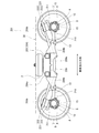
- FIG. 1 is a side view of a railway vehicle carriage 1 including a axle box 10 according to the first embodiment.
- the front side of the paper surface may be referred to as “left”, the back side of the paper surface as “right”, the left side of the paper surface as “front”, and the right side of the paper surface as “back”.
- a railcar bogie (hereinafter referred to as a bogie) 1 includes a bogie frame 3 for supporting a vehicle body 30 via an air spring 2.
- the bogie frame 3 includes a lateral beam 4 extending in the vehicle width direction at the center of the bogie 1 in the longitudinal direction of the vehicle, and side beams 5 extending from both ends of the lateral beam 4 in the longitudinal direction of the vehicle.
- a pair of axles 6 extending along the vehicle width direction are disposed on both sides of the bogie frame 3 in the longitudinal direction of the vehicle.
- Wheels 7 are press-fitted on both sides of the axle 6 in the vehicle width direction.
- the axle 6 and the wheel 7 constitute an axle 20.
- the pair of wheel shafts 20 provided on the carriage 1 are arranged on both sides of the carriage frame 3 in the longitudinal direction of the vehicle.
- Bearings 8 are provided at both ends of the axle 6 in the vehicle width direction so as to rotatably support the wheels 7 outside the wheels 7 in the vehicle width direction.
- the bearings 8 are attached to the axle box body 11 of the axle box 10. Be contained.
- the axle box main body 11 is elastically connected to the carriage frame 3 by an axle beam 13 integrated with the axle box 10 and an axle spring 21.
- the axle box 10 includes an axle box body 11, a cover body 12, an axle beam 13, and a lid 15.
- the axle box main body 11 is a member that covers the bearing 8 from above
- the cover body 12 is a member that covers the bearing 8 from below.
- the axle box main body 11 is connected to the vehicle longitudinal direction end portion 5 a of the side beam 5 in the vertical direction by an axle spring 21.
- the cover body 12 is fixed to the axle box main body 11 by fastening members 16 such as bolts. As described above, the cover body 12 is attached to the axle box main body 11, thereby forming a truly cylindrical accommodation space A for accommodating the bearing 8.
- the shaft beam 13 connects the shaft box body 11 and the side beam 5 in the longitudinal direction of the vehicle. Specifically, a shaft beam 13 formed integrally with the shaft box body 11 extends from the shaft box body 11 toward the side beam 4 in the vehicle longitudinal direction. And the front-end
- the lid 15 is a member that covers the axle 6 and the bearing 8 from the outside in the vehicle width direction.
- the lid 15 is attached to the axle box main body 11 from the outside in the vehicle width direction by a plurality of fastening members 17 (for example, bolts).
- the lid 15 is an adapter for attaching a grounding device and a speed generator as required, and the lid 15 may not be provided in the carriage 1.
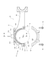
- FIG. 2 is an exploded side view of the axle box 10 shown in FIG. 1 with the lid 15 removed.
- the axle box 10 is divided into an axle box main body 11 formed integrally with the axle beam 13 and a cover body 12.
- Each of the inner surface S10 of the axle box body 11 and the inner surface S20 of the cover body 12 has a shape that forms a part of a perfect circle centered on the axle center O in a side view.
- the axle box main body 11 has a spring seat 11a at the top thereof.
- the upper surface S14 of the spring seat 11a is a support surface that supports the shaft spring 21, and forms the upper surface of the shaft box body 11. From the support surface S14, a substantially cylindrical protruding portion 11b protrudes upward.
- the protrusion 11b overlaps with an axis P2 extending in the vehicle longitudinal direction through the center C in the vehicle width direction of the accommodation space A (hereinafter simply referred to as “center C of the accommodation space A”) (FIG. 3, FIG. 3). (See FIG. 4).
- the protrusion part 11b and the center C of the accommodation space A do not need to correspond, and the protrusion part 11b and the accommodation space A may be offset.
- the protrusion 11b is inserted into a through hole (not shown) formed in the lower surface of the shaft spring 21 (see FIG. 1), thereby positioning the shaft spring 21 on the upper surface S14 of the shaft box body 11.
- FIG. 3 is a cross-sectional view taken along line III-III in FIG.
- the upper portion of the bearing 8 is accommodated at the approximate center of the axle box body 11 in the vehicle width direction.
- the axle box main body 11 has a pair of flanges 11c that partially protrudes radially inward from the inner surface S10.
- the collar part 11c is circular arc shape in side view (refer FIG. 2).
- the bearing 8 accommodated in the axle box main body 11 is positioned by being clamped from both sides in the vehicle width direction by the pair of flange portions 11c.
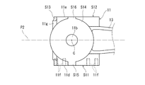
- FIG. 4 is a view taken along arrow IV in FIG.
- the axle box body 11 includes a first side surface S ⁇ b> 11 outside the vehicle width direction with respect to the vehicle width direction center C, and a second side surface S ⁇ b> 12 inside the vehicle width direction with respect to the center C. have.
- a flat first seat surface portion 11 d is formed on the first side surface S ⁇ b> 11 of the axle box main body 11.
- a flat second seat surface portion 11e having the same contour as the first seat surface portion 11d of the first side surface S11 is also formed on the second side surface S12. Since the lid 15 is attached to the first side surface S11 with a bolt 17 (see FIG. 1), a plurality of female screws 11f that are screwed with the male screw of the bolt 17 are formed. By attaching the lid 15 to the first side surface S11, the lid 15 closes the housing space A of the axle box body 11 from the outside in the vehicle width direction. Since the lid 15 is not attached to the second side surface S12 on the inner side in the vehicle width direction, unlike the first seat surface portion 11d, the female screw is not formed on the second seat surface portion 11e of the second side surface S12.
- a first horizontal plane S15 chucked by a lifting device such as a hydraulic jack is provided on the outer side in the vehicle width direction of the spring seat 11a in the upper part of the axle box body 11, and a second horizontal surface is provided on the inner side in the vehicle width direction of the spring seat 11a.
- a horizontal plane S16 is provided.
- the first horizontal plane S15 and the second horizontal plane S16 have a rectangular shape that is long in the longitudinal direction of the vehicle, but the second horizontal plane S16 has a smaller dimension in the vehicle width direction than the first horizontal plane S15.
- Both the first horizontal plane S15 and the second horizontal plane S16 are provided at the same position as the support surface S14 in the vertical direction.
- the axle box body 11 of the axle box 10 is placed on the first horizontal plane S15 on the jack of the wheel lathe device.
- the tread surface of the wheel 7 can be turned from below by chucking and pushing up the axle box 10 that supports the axle 5 with the jack.
- FIG. 5 is a view of the axle box body 11 to which the obstruction device 35 is attached as seen from the V direction shown in FIG.
- the obstruction device 35 includes an obstruction portion 35 a that overlaps the wheel 7 when viewed from the vehicle longitudinal direction, and a connecting portion 35 b that connects the obstruction portion 35 a and the axle box body 11. ing.
- the evacuation part 35a is being fixed by the connection part 35b and the fastening member 36 (for example, a volt
- the connecting portion 35 b has a plate-like attachment metal 35 c that is attached to the axle box main body 11.
- the attachment metal 35c is attached to the receiving seats 11g and 11h of the axle box main body 11 by a plurality of fastening members 37 (for example, bolts).
- the receiving seats 11g and 11h are provided on the outer side surface S13 of the axle box body 11 on the outer side in the vehicle longitudinal direction with respect to the center C of the housing space A.
- each of the receiving seats 11g and 11h has a substantially rectangular shape that is long in the vehicle width direction, and is formed into a symmetrical shape in the vehicle width direction with respect to the center C of the housing space A.
- the receiving seats 11g and 11h are each provided with a fastening surface F for fastening the connecting portion 35b of the obstruction device 35 with a bolt 37.
- the receiving seats 11g and 11h are arranged such that the fastening surface F is inclined obliquely downward toward the vehicle longitudinal direction outer side with respect to the side surface S13 (see FIG. 2).
- the fastening surface F is provided with a plurality of insertion holes 11i to 11k through which the bolts 37 are inserted.
- the insertion holes 11i to 11k female screws that are screwed into the male screws of the bolts 37 are formed. That is, in the present embodiment, the insertion holes 11i to 11k are screw holes.
- the plurality of screw holes 11i to 11k are arranged symmetrically in the vehicle width direction with respect to the center C of the accommodation space A. Specifically, of the plurality of screw holes 11i to 11k, the first screw hole 11i is formed so as to overlap the center C of the accommodation space A when viewed from the vehicle longitudinal direction outer side.
- the 2nd screw hole 11j and the 3rd screw hole 11k are formed in the vehicle width direction both sides of the 1st screw hole 11i.
- the second screw hole 11j and the third screw hole 11k are arranged at the same interval from the first screw hole 11i in the vehicle width direction.
- the four through holes of the mounting bracket 35c are connected to the first insertion hole 11i and the second insertion hole 11j of the receiving seats 11g and 11h and the vehicle.
- the connecting portion 35 b is fixed by the bolt 37. Accordingly, the obstruction device 35 can be attached to the seats 11g and 11h that are symmetrical in the vehicle width direction while being moved closer to the vehicle width direction inner side, that is, the wheel side (in this example, the right and left direction right side). it can.
- the axle box main body 11 of the axle box 10 is manufactured through a casting process and a machining process.
- a shaft box original 51 (see FIGS. 6 and 7) is formed by casting in which a molten metal material (for example, carbon steel) flows into the mold.
- the axle box main body 11 is formed by machining the molded axle box original 51.
- a molten metal material for example, carbon steel
- FIG. 6 is a cross-sectional view (corresponding to a cross-sectional view taken along the line III-III in FIG. 2) of the shaft box original 51 formed in the casting process.
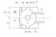
- FIG. 7 is a top view of the axle box original 51 (corresponding to a view taken along the arrow IV in FIG. 2).
- the axle box original 51 is formed in a symmetrical shape in the vehicle width direction with respect to the center C of the accommodation space A that accommodates the bearing 8.
- the surfaces S50 to S52 and the surfaces S54 to S56 of the axle box original 51 are subjected to cutting in the next processing step, as will be described later.
- the surface having the same contour shape as the surfaces S10 to S12 and S14 to S16 of the shaft box main body 11 is formed in the shaft box original 51. Therefore, the surfaces S50 to S52 and S54 to S56 of the shaft box original 51 have a machining allowance with respect to the surfaces S10 to S12 and S14 to S16 of the shaft box body 11 which is a finished product.
- the outer peripheral surface of the protruding portion 51b and the fastening surface F of the receiving seats 51g and 51h also have a machining allowance.
- the projecting portion 11b and the receiving seats 11g and 11h of the axle box body 11 are formed by cutting the outer peripheral surface of the projecting portion 51b and the fastening surface F of the receiving seats 51g and 51h in the machining process.
- the axle box original 51 has a first horizontal plane S55 corresponding to the first horizontal plane S15 for chuck described above on the outer side in the vehicle width direction of the upper spring seat 51a.
- the second horizontal plane S56 has the same shape as the first horizontal plane S55.
- the receiving seats 51g and 51h for attaching the obstruction device 35 are formed in a symmetrical shape in the vehicle width direction with respect to the center C of the accommodation space A.
- the axle box original 51 having such a shape is manufactured using a common mold.
- a pair of axle box bodies hereinafter referred to as a pair of left and right axle box bodies
- the mold used in the casting process is common.
- the common axle box original 51 is formed regardless of the axle box body (left hand) arranged on the left side and the axle box body (right hand) arranged on the right side in a side view.
- the left-hand shaft box main body and the right-hand shaft box main body are formed by machining the shaft box prototype 51. The details of machining in the machining process will be described below. Here, machining for forming the left-handed axle box body 11 will be described.
- the surfaces S50 to S52 and S54 to S56 of the shaft box original 51 are respectively cut to form the same contour shape as the corresponding surfaces S10 to S12 and S14 to S16 of the shaft box body 11.
- screw hole processing for attaching the lid 15 is performed on the first seat surface portion 51d of the first side surface S51. That is, after forming a lower hole in the first bottom surface portion 51d of the first side surface S51, screw hole processing is performed to form a female screw 11f that is screwed into the male screw of the bolt 16 in the lower hole.
- the first side S11 of the left-hand axle box body 11 is formed. Since the lid 15 is provided only on the outer surface S11 of the axle box body 11 in the vehicle width direction, the second seating surface portion 51e of the second side surface S52 that is the inner side surface in the vehicle width direction is not subjected to screw hole machining. .
- the machining process is not limited to this.
- the internal thread 11f may be formed before the cutting process of the surface S50 of the axle box original 51, and the order of each process can be changed as appropriate.
- the screw holes 11i to 11k are formed in the receiving seats 51g and 51h by the screw hole processing for attaching the obstruction device 35. It should be noted that either one of the screw holes 11j and 11k on both sides in the vehicle width direction may not be formed depending on the arrangement location of the axle box body 11. For example, in the left-hand axle box body 11, the third screw hole 11k on the outer side in the vehicle width direction may not be formed.
- the left-handed and right-handed shaft box body 11 is formed from the same-shaped axle box original 51.
- the shortest distance between the first side surface S11 and the center C of the accommodation space A is approximately the shortest distance between the second side surface S12 and the center C.
- the end portion on the inner side in the vehicle width direction of the axle box body 11 having the second side surface S12 is partially To be cut.
- the axle box main body 11 having an asymmetric shape in the vehicle width direction is formed also by cutting for reducing the weight of the axle box main body 11.
- the axle box 10 of the carriage 1 configured as described above has the following effects.
- a symmetrical axle box original 51 is formed in the vehicle width direction.
- the types of axle box original 51 can be reduced, and the mold cost can be reduced by sharing the mold. Therefore, when manufacturing the axle box main body 11, a parts management cost and a manufacturing cost can be reduced.
- axle box original 51 that is symmetrical in the vehicle width direction is cast by a common mold, and then the axle box can be easily selected according to the location of the axle box body 11. Since it becomes possible to manufacture the main body 11, when manufacturing the axial box main body 11, the suitable axle box 10 which reduced the part management cost and the manufacturing cost can be provided.
- the axle box body 11 When the lid 15 is attached to the first side surface S11 of the axle box body 11 with the bolts 17, the axle box body 11 is asymmetric in the machining process while the axle box original 51 having a symmetrical shape is formed in the vehicle width direction in the casting process.
- the female screw 11f By forming the female screw 11f on the first side surface S11 so as to become, it is possible to manufacture the axle box body 11 having an asymmetric shape in the vehicle width direction while reducing the mold cost.
- a flat first seat surface portion 11d to which the lid 15 is attached is formed on the first side surface S11, and a second seat surface portion 11e having the same contour as the first seat surface portion 11d is also formed on the second side surface S12. Therefore, in manufacturing the pair of left and right axle box bodies 11, a common mold can be used, and the mold cost can be reduced.
- the axle shaft original 51 having a symmetrical shape in the vehicle width direction is cast with a common mold, and then the axle having a side surface opposite to the side surface to which the lid 15 is attached.
- the shaft box main body 11 can be easily formed by partially cutting the vehicle width direction end portion of the box original form 51. Further, the axle box body 11 having an asymmetric shape in the vehicle width direction can be manufactured while reducing the mold cost.
- the spring seat is placed on the upper part of the original axle box 51 in the casting process. Since the chuck horizontal planes S55 and S56 are formed on both sides in the vehicle width direction of 11a, a common mold is used when manufacturing the pair of axle box bodies 11 provided on both sides of the axle 6 in the vehicle width direction. The mold cost can be reduced.
- the axle box 210 according to the second embodiment is obtained by partially changing the shape and the like from the axle box 10 according to the first embodiment.
- bogie 201 provided with the axle box 210 which concerns on 2nd Embodiment also changes the structure of the trolley
- bogie 201 provided with the same are demonstrated focusing on a different point from the axle box 10 and the trolley
- FIG. 8 is a side view of the carriage 201 according to the second embodiment.
- the bogie frame 203 includes a horizontal beam 204 that extends in the vehicle width direction at the center of the vehicle 1 in the longitudinal direction of the vehicle 1.
- receiving seats 204b are formed on which the distal end portion of the shaft beam 13 is formed.
- a leaf spring 209 extending in the longitudinal direction of the vehicle is bridged between the axle box 210 and the side cover 204.
- the leaf spring 209 supports the vehicle width direction opposite end portions 204a of the lateral beam 204 from below at the vehicle longitudinal direction central portion 209a, and the vehicle longitudinal direction end portion 209b of the leaf spring 209 is supported by the axle box body 211.
- the leaf spring 209 has the function of the shaft spring (primary suspension) 21 of the first embodiment and the function of the side beam 5 of the first embodiment.
- the longitudinal end 209 b of the vehicle in the longitudinal direction of the leaf spring 209 is supported from below by the axle box body 211 via the support member 231.
- the support member 231 includes a receiving member 232 and a vibration isolating rubber 233.
- the receiving member 232 has a substantially rectangular shape in plan view, and has a bottom wall portion that supports the lower surface of the leaf spring 209 and side wall portions that protrude upward from both ends in the vehicle longitudinal direction of the bottom wall portion. is doing.
- the anti-vibration rubber 233 has a substantially cylindrical shape, and is inserted between the axle box main body 211 and the receiving member 232.
- FIG. 9 is a view corresponding to FIG. 2 of the axle box 210 according to the second embodiment.
- the axle box main body 211 has a spring seat 211 a including an upper surface S ⁇ b> 214 that is in surface contact with the lower surface of the vibration isolating rubber 233.
- the upper surface S214 of the spring seat 211a is a support surface that supports the plate spring 209 via the receiving member 232 and the vibration isolating rubber 233.
- the support surface S214 of the spring seat 211a is substantially parallel to the lower surface of the leaf spring 209, and is inclined obliquely downward toward the center side in the vehicle longitudinal direction.
- the spring seat 211a may be configured separately from the axle box main body 211.
- FIG. 10 is a view corresponding to FIG. 4 of the axle box main body 211 according to the second embodiment.
- both the first horizontal plane S215 and the second horizontal plane S216 are located below the inclined support surface S214.
- cover 15 is attached only to 1st side surface S211 which is the side surface of the vehicle width direction outer side similarly to the axle box main body 11 which concerns on 1st Embodiment. Therefore, the screw hole processing for forming the screw hole 211f is applied to the first seat surface portion 211d of the first side surface S211, and the screw hole processing is not applied to the second side surface S212 which is the inner side surface in the vehicle width direction.
- FIG. 11 is a view corresponding to FIG. 7 of the axle box original object 251 according to the second embodiment.
- the axle box original 251 is formed into a symmetrical shape in the vehicle width direction with respect to the center C of the accommodation space A, like the axle box original 51 of the first embodiment.
- flat seat surface portions 251d and 251e having the same contour are formed on both the first side surface S251 and the second side surface S252.
- the shaft box original 251 has a first horizontal plane S255 corresponding to the first horizontal plane S215 for chuck on the outer side in the vehicle width direction of the upper spring seat 251a, and the first horizontal plane on the inner side in the vehicle width direction.
- the second horizontal plane S256 has the same shape as S255.
- a receiving seat 251g for attaching the obturator is formed in a symmetrical shape with respect to the center C of the accommodation space A in the vehicle width direction.
- a common axle box original 251 is formed regardless of the left-handed axle box body 211 and the right-handed axle box body 211.
- the shaft box main body 211 is formed by applying the machining described in the first embodiment to the shaft box original 251.
- the same effect as that of the first embodiment can be obtained by the second embodiment. That is, when manufacturing the left-hand shaft box main body and the right-hand shaft box main body, it is possible to use the common shaft box original 251. For this reason, the types of axle box originals 251 can be reduced, and the mold cost can be reduced by using a common mold. Therefore, in manufacturing the pair of left and right axle box bodies 211, the parts management cost and the manufacturing cost can be reduced. Therefore, the axle box main body 211 manufactured from the axle box original 251 having a symmetrical shape in the vehicle width direction is not limited to the carriage 1 including the general carriage frame 3, and is also applied to the carriage 201 using the leaf spring 209. Is possible.
- the present invention is not limited to the above-described embodiment, and the configuration can be changed, added, or deleted without departing from the spirit of the present invention.
- the above embodiments may be arbitrarily combined with each other.
- some configurations or methods in one embodiment may be applied to other embodiments.
- a part of the configuration in the embodiment can be arbitrarily extracted separately from the other configurations in the embodiment.
- the axle boxes 10 and 210 are divided into the axle box bodies 11 and 211 and the cover body 12 at a portion below the axle center O, and the axle box body 11 in a side view.
- 211 has a substantially semicircular shape forming a part of a perfect circle, but is not limited to this configuration.
- the inner surfaces of the axle box bodies 11 and 211 may have a perfect circle shape, that is, the accommodation space A in which the bearing 8 is accommodated is defined only by the inner surfaces of the axle box bodies 11 and 211. May be.
Landscapes
- Engineering & Computer Science (AREA)
- Mechanical Engineering (AREA)
- Vehicle Body Suspensions (AREA)
- Body Structure For Vehicles (AREA)
Abstract
鉄道車両用軸箱は、車軸を支持する軸受が収容される軸箱本体を備える。軸箱本体は、軸受が収容される収容空間を画定する内面と、内面よりも外側で収容空間の車幅方向の中心に対して車幅方向一方側に設けられた第1側面と、内面よりも外側で前記中心に対して車幅方向他方側に設けられた第2側面と、を有する。車幅方向において、第1側面と収容空間の車幅方向中心との間の最短距離と、第2側面と当該中心との間の最短距離とが、互いに同一である。
Description
本発明は、鉄道車両用軸箱及びその製造方法に関する。
鉄道車両用台車には、車軸を支持する軸受を収容する軸箱が当該車軸の車幅方向両側に設けられている(例えば、特許文献1参照)。軸箱は、例えばアルミ合金等の金属を鍛造することにより製造されたり、溶融した金属を鋳型に流入することによる鋳造によって製造される。
このような軸箱は、車幅方向に対して非対称な構造を有している。そのため、1台車あたり4つの軸箱が設けられるが、側面視において左側に配置される軸箱(左勝手)と右側に配置される軸箱(右勝手)の合計2種類の軸箱が存在する。
具体的には、例えば、軸受が収容される軸箱のカバー部材が、軸箱の車幅方向一方側(車幅方向外側)に設けられる。このとき、カバー部材をボルト固定するための挿通孔が、軸箱の車幅方向外側のみに機械加工により形成される。
また、ジャッキ等の押上装置にチャックさせるための水平面が軸箱上面に設けられるが、当該水平面は軸箱上面のうち車幅方向一方側に設けられる。
このように、従来の軸箱は、車幅方向に対して非対称な構造を有しているため、同じ軸箱にも拘わらず、左勝手用の軸箱と右勝手用の軸箱とをそれぞれ別部品として管理しなければならず、その管理コストが大きいという課題があった。
さらに、複数種の軸箱を製造するにあたっては、その数に応じた鋳型を用意する必要があるため、鋳型費用も増加するという課題があった。
そこで本発明は、鉄道車両用軸箱を製造するにあたって、部品管理コスト及び製造コストを削減することを目的としている。
本発明の一形態に係る鉄道車両用軸箱の製造方法は、車軸を支持する軸受が収容される軸箱本体を備える軸箱を製造する方法であって、前記軸受が収容される収容空間を有する軸箱原形物を鋳造により車幅方向に対称な形状に成形する鋳造工程と、前記軸箱原形物を機械加工して前記軸箱本体を形成する加工工程と、を備える。
前記方法によれば、軸受が収容される収容空間を有する軸箱原形物を車幅方向に対称な形状に成形することによって、車軸の車幅方向両側に設けられる一対の軸箱本体を製造するにあたって、軸箱原形物の種類を低減できると共に、鋳型の共通化により鋳型費用を削減することができる。よって、鉄道車両用台車の軸箱本体を製造するにあたって、部品種類及び製造コストを削減することができる。
本発明の一形態に係る鉄道車両用軸箱は、車軸を支持する軸受が収容される軸箱本体を備え、前記軸箱本体は、前記軸受が収容される収容空間を画定する内面と、前記内面よりも外側で前記収容空間の車幅方向の中心に対して車幅方向一方側に設けられた第1側面と、前記内面よりも外側で前記中心に対して車幅方向他方側に設けられた第2側面と、を有し、車幅方向において、前記第1側面と前記中心との間の最短距離と、前記第2側面と前記中心との間の最短距離とが、互いに同一である。
前記構成によれば、共通の鋳型により車幅方向に対称な軸箱原形物を鋳造してから容易に軸箱本体を製作することができ、軸箱本体の製造時における部品種類及び製造コストを削減した好適な軸箱を提供することができる。
本発明によれば、鉄道車両用軸箱を製造するにあたって、部品管理コスト及び製造コストを削減することができる。
以下、図面を参照しながら実施形態について説明する。なお、同一の又は対応する要素には全ての図を通じて同一の符号を付して重複する詳細説明を省略する。
(第1実施形態)
図1は、第1実施形態に係る軸箱10を備える鉄道車両用台車1の側面図である。図1において、説明の便宜上、紙面手前側を「左」、紙面奥側を「右」、紙面左側を「前」、紙面右側を「後」と呼ぶことがある。図1に示すように、鉄道車両用台車(以下、台車と呼ぶ)1は、空気バネ2を介して車体30を支持するための台車枠3を備えている。台車枠3は、台車1の車両長手方向中央において車幅方向に延びる横ばり4と、横ばり4の車幅方向両端部から車両長手方向に延びる側ばり5とを有している。
図1は、第1実施形態に係る軸箱10を備える鉄道車両用台車1の側面図である。図1において、説明の便宜上、紙面手前側を「左」、紙面奥側を「右」、紙面左側を「前」、紙面右側を「後」と呼ぶことがある。図1に示すように、鉄道車両用台車(以下、台車と呼ぶ)1は、空気バネ2を介して車体30を支持するための台車枠3を備えている。台車枠3は、台車1の車両長手方向中央において車幅方向に延びる横ばり4と、横ばり4の車幅方向両端部から車両長手方向に延びる側ばり5とを有している。
台車枠3の車両長手方向両側には、それぞれ車幅方向に沿って延びる一対の車軸6が配置されている。車軸6の車幅方向両側には車輪7が圧入される。車軸6及び車輪7は輪軸20を構成する。そして、台車1に設けられた一対の輪軸20は、台車枠3の車両長手方向両側に離間して配置されている。車軸6の車幅方向両側の端部には、車輪7よりも車幅方向外側にて車輪7を回転自在に支持する軸受8が設けられ、その軸受8は軸箱10の軸箱本体11に収容される。軸箱本体11は、軸箱10と一体となった軸ばり13と、軸バネ21により台車枠3に弾性的に連結される。
軸箱10は、軸箱本体11と、カバー体12と、軸ばり13と、蓋15とを備えている。軸箱本体11は、軸受8を上側から覆う部材であり、カバー体12は、軸受8を下側から覆う部材である。軸箱本体11は、軸バネ21によって、側ばり5の車両長手方向端部5aと上下方向に接続されている。カバー体12は例えばボルト等の締結部材16によって軸箱本体11に固定される。このように、カバー体12が軸箱本体11に取り付けられることにより、軸受8を収容する真円柱状の収容空間Aが形成される。
軸ばり13は、軸箱本体11と側ばり5とを車両長手方向に連結している。具体的には、軸箱本体11と一体に成形された軸ばり13が、当該軸箱本体11から車両長手方向のうち横ばり4側に向かって延びている。そして、軸ばり13の先端部は側ばり5の受け座5bに対して、ゴムブッシュ及び心棒(図示せず)を介して弾性的に連結されている。
また、蓋15は、車軸6及び軸受8を車幅方向外側から覆う部材である。蓋15は、複数の締結部材17(例えば、ボルト)によって軸箱本体11に車幅方向外側から取り付けられる。ここで、蓋15は、必要に応じて接地装置や速度発電機を取り付けるためのアダプタであり、台車1において蓋15を設けなくてもよい。
図2は、図1に示す軸箱10の蓋15を取り外した状態での分解側面図である。図2に示すように、軸箱10は、軸ばり13と一体に成形された軸箱本体11と、カバー体12とに分割される。軸箱本体11の内面S10及びカバー体12の内面S20はそれぞれ、側面視において、車軸中心Oを中心とする真円の一部をなす形状を有している。
軸箱本体11は、その上部にバネ座11aを有している。バネ座11aの上面S14は、軸バネ21を支持する支持面であり、軸箱本体11の上面を形成している。支持面S14からは、略円柱状の突出部11bが上方に突出している。突出部11bは、収容空間Aの車幅方向中心C(以下、単に「収容空間Aの中心C」と呼ぶ。)を通り車両長手方向に延びる軸線P2と平面視で重なっている(図3、図4参照)。なお、突出部11bと収容空間Aの中心Cとが一致する必要はなく、突出部11bと収容空間Aとがオフセットしてもよい。突出部11bは、軸バネ21(図1参照)の下面に形成された貫通孔(図示せず)に挿入されることで、当該軸バネ21を軸箱本体11の上面S14において位置決めする。
図3は、図2のIII-III線断面図である。図3に示すように、軸箱本体11の車幅方向略中央において、軸受8の上側部分が収容されている。軸箱本体11は、その内面S10から径方向内側に向けて部分的に突出する一対の鍔部11cを有している。鍔部11cは、側面視において円弧状である(図2参照)。軸箱本体11に収容される軸受8は、一対の鍔部11cによって車幅方向両側から挟持されることで位置決めされる。
図4は、図2のIV矢視図である。図3及び4に示すように、軸箱本体11は、車幅方向中心Cに対して車幅方向外側の第1側面S11と、当該中心Cに対して車幅方向内側の第2側面S12とを有している。
軸箱本体11の第1側面S11には、平坦な第1座面部11dが形成されている。他方、第2側面S12においても、第1側面S11の第1座面部11dと同じ輪郭を有する平坦な第2座面部11eが形成されている。第1側面S11には、蓋15がボルト17(図1参照)によって取り付けられるため、当該ボルト17の雄ネジと螺合する複数の雌ネジ11fが形成されている。蓋15が第1側面S11に取り付けられることで、当該蓋15は軸箱本体11の収容空間Aを車幅方向外側から閉じる。蓋15は、車幅方向内側の第2側面S12には取り付けられないため、当該第2側面S12の第2座面部11eには第1座面部11dと異なり、雌ネジは形成されていない。
また、軸箱本体11の上部において、バネ座11aの車幅方向外側には油圧ジャッキ等の押上装置にチャックされる第1水平面S15が設けられ、バネ座11aの車幅方向内側には第2水平面S16が設けられている。第1水平面S15及び第2水平面S16は、車両長手方向に長い長方形状であるが、第2水平面S16は、第1水平面S15より車幅方向寸法が小さい。第1水平面S15及び第2水平面S16はいずれも、上下方向において支持面S14と同一の位置に設けられている。
このような構成により、車両の走行等により偏摩耗が生じた車輪7を在姿削正する車輪削正作業において、車輪旋盤装置のジャッキに軸箱10の軸箱本体11を第1水平面S15でチャックさせて、当該ジャッキによって輪軸5を支持する軸箱10を上方に押し上げることで、車輪7の踏面を下方から旋削可能である。
図5は、排障器35が取り付けられた軸箱本体11を図2に示すV方向から見た図である。図5に示すように、排障器35は、車両長手方向から見て車輪7と重なる排障部35aと、当該排障部35aと軸箱本体11とを連結する連結部35bとを有している。排障部35aは、連結部35bと締結部材36(例えば、ボルト及びナット)によって固定されている。連結部35bは、軸箱本体11に取り付けられる板状の取付金35cを有している。取付金35cは、軸箱本体11の受け座11g,11hに複数の締結部材37(例えば、ボルト)によって取り付けられている。
受け座11g,11hは、軸箱本体11の外面のうち、収容空間Aの中心Cに対して車両長手方向外側の側面S13に設けられている。車両長手方向外側から見て、受け座11g,11hはいずれも、車幅方向に長い略矩形の形状を有しており、収容空間Aの中心Cを基準として車幅方向に対称な形状に成形されている。また、受け座11g,11hにはそれぞれ、排障器35の連結部35bをボルト37で締結するための締結面Fが設けられている。受け座11g,11hは、締結面Fが側面S13に対して車両長手方向外側に向けて斜め下方に傾斜するように配置されている(図2参照)。締結面Fには、ボルト37が挿通される複数の挿通孔11i~11kが設けられている。
挿通孔11i~11kには、ボルト37の雄ネジと螺合する雌ネジが形成されている。即ち、本実施形態では、挿通孔11i~11kは、ネジ孔である。そして、複数のネジ孔11i~11kは、収容空間Aの中心Cを基準に車幅方向に対称に配置されている。具体的には、複数のネジ孔11i~11kのうち第1ネジ孔11iは、車両長手方向外側から見て収容空間Aの中心Cと重なるように形成されている。そして、第1ネジ孔11iの車幅方向両側に、第2ネジ孔11j及び第3ネジ孔11kが形成されている。第2ネジ孔11j及び第3ネジ孔11kは、第1ネジ孔11iから車幅方向に同一の間隔をあけて配置されている。
連結部35bの取付金35cには、ボルト37が貫通する4つの貫通孔が形成されている。本実施形態のように、「左前」の軸箱10の軸箱本体11では、取付金35cの4つの貫通孔を、受け座11g,11hの第1挿通孔11i及び第2挿通孔11jと車両長手方向に重なるように配置した上で、ボルト37によって連結部35bを固定している。これにより、車幅方向に対称な形状である受け座11g,11hに対して、排障器35が車幅方向内側、即ち、車輪側(この例では、左右方向右側)に寄せて取り付けることができる。
次に軸箱10の製造方法について説明する。軸箱10の軸箱本体11は、鋳造工程及び加工工程を経て、製造される。鋳造工程では、溶融した金属材料(例えば、炭素鋼)を鋳型に流入する鋳造により軸箱原形物51(図6及び7参照)が成形される。そして、成形された軸箱原形物51を機械加工することで軸箱本体11は形成される。以下、鋳造工程により製造される軸箱原型物51の構造について説明する。
図6は、鋳造工程において成形された軸箱原形物51の断面図(図2のIII-III線断面図に相当する)である。図7は、軸箱原形物51の上面図(図2のIV矢視図に相当する)である。図6及び7に示すように、軸箱原形物51は、軸受8を収容する収容空間Aの中心Cを基準に車幅方向に対称な形状に成形されている。ここで、軸箱原形物51の面S50~S52及び面S54~S56には、後述するように、次の加工工程において切削加工が施される。この切削加工により、軸箱原形物51において、軸箱本体11の面S10~S12、S14~S16と同一の輪郭形状を有する面が形成される。そのため、軸箱原形物51の面S50~S52,S54~S56は、完成品である軸箱本体11の面S10~S12,S14~S16に対して削り代を有している。
軸箱原形物51において、突出部51bの外周面及び受け座51g,51hの締結面Fも削り代を有している。突出部51bの外周面及び受け座51g,51hの締結面Fも加工工程において切削加工することによって、軸箱本体11の突出部11b及び受け座11g,11hが形成される。
また、鋳造工程の際には、軸箱原形物51の第1側面S51及び第2側面S52の両方に、同じ輪郭を有する平坦な座面部51d,51eが形成されている。そして、第1側面S51と収容空間Aの中心Cとを結ぶ最短距離L11は、第2側面S52と当該中心Cとを結ぶ最短距離L12と等しい。また、軸箱原形物51は、その上部のバネ座51aの車幅方向外側に、上述のチャック用の第1水平面S15に対応する第1水平面S55を有しており、車幅方向内側に第1水平面S55と同じ形状の第2水平面S56を有している。
また、収容空間Aの車両長手方向外側の側面S53においても、排障器35を取り付けるための受け座51g,51hが収容空間Aの中心Cを基準にして車幅方向に対称な形状に成形されている。このような形状を有する軸箱原形物51は、共通の鋳型を用いて製造される。そして、軸箱原形物51は、車幅方向に対称な形状を有するため、車軸6の車幅方向(左右方向)両側に設けられる一対の軸箱本体(以下、左右一対の軸箱本体と呼ぶ。)を製造する場合、鋳造工程で用いる鋳型は共通となる。即ち、鋳造工程では、側面視において左側に配置される軸箱本体(左勝手)と右側に配置される軸箱本体(右勝手)に関わらず、共通の軸箱原形物51が成形される。そして、次の加工工程において、軸箱原型物51を機械加工することで、左勝手の軸箱本体と右勝手の軸箱本体が形成される。以下、加工工程における機械加工の詳細について説明する。なお、ここでは左勝手の軸箱本体11を形成するための機械加工について説明する。
まず、軸箱原形物51の面S50~S52,S54~S56をそれぞれ切削加工することで、軸箱本体11のうち対応する面S10~S12,S14~S16と同一の輪郭形状を形成する。次に、第1側面S51の第1座面部51dに、蓋15を取り付けるためのネジ孔加工が施される。即ち、第1側面S51の第1底面部51dに下孔を形成した後、当該下孔にボルト16の雄ネジと螺合する雌ネジ11fを形成するネジ孔加工が行われる。このように、軸箱原形物51の第1側面S51を機械加工することによって、左勝手の軸箱本体11の第1側面S11が形成される。なお、蓋15は、軸箱本体11の車幅方向外側の面S11にのみ設けられるため、車幅方向内側の側面である第2側面S52の第2座面部51eにはネジ孔加工は施されない。
なお、機械加工の工程はこれに限定されるものではない。例えば、軸箱原形物51の面S50の切削工程の前に雌ネジ11fを形成してもよく、その他、各工程の順序は適宜変更可能である。
また、受け座51g,51hにも、排障器35を取り付けるためのネジ孔加工が施され、ネジ孔11i~11kが形成される。なお、軸箱本体11の配置場所に応じて、車幅方向両側のネジ孔11j,11kのうちいずれか一方のネジ孔は形成されなくてもよい。例えば、左勝手の軸箱本体11においては、車幅方向外側の第3ネジ孔11kは形成されなくてもよい。
以上の加工工程により、同一形状の軸箱原形物51から、左勝手と右勝手の軸箱本体11が形成される。このような軸箱本体11では、車幅方向において、第1側面S11と収容空間Aの中心Cとの間の最短距離は、第2側面S12と当該中心Cとの間の最短距離とが略同一である。本実施形態では、軸箱本体11の重量を軽減するために、第2側面S12を有する軸箱本体11の車幅方向内側の端部(この例では、左右方向右側の端部)が部分的に切削加工される。このとき、軸箱本体11において、第2側面S12と収容空間Aの中心Cとの間の最短距離L3は、第1側面S11と当該中心Cとの間の最短距離L1よりも小さくなる(図3参照)。そのため、本実施形態では、軸箱本体11の重量を軽減するための切削加工によっても、車幅方向に非対称な形状を有する軸箱本体11が形成される。
以上のように構成された台車1の軸箱10は、以下の効果を奏する。
軸箱10の軸箱本体11を製造する工程のうち鋳造工程において、車幅方向に対称形状の軸箱原形物51が成形される。これにより、左右一対の軸箱本体11を製造するにあたって、共通の軸箱原形物51を用いることが可能となる。そのため、軸箱原形物51の種類を低減できると共に、鋳型の共通化により鋳型費用を削減することができる。よって、軸箱本体11を製造するにあたって、部品管理コスト及び製造コストを削減することができる。
また、左右一対の軸箱本体11を製造する場合に、共通の鋳型により車幅方向に対称な軸箱原形物51を鋳造してから、軸箱本体11の配置場所に応じて容易に軸箱本体11を製造することが可能となるため、軸箱本体11の製造するにあたって、部品管理コスト及び製造コストを削減した好適な軸箱10を提供することができる。
軸箱本体11の第1側面S11に蓋15をボルト17で取り付ける場合、鋳造工程では、車幅方向に対称形状の軸箱原形物51を成形しながらも、加工工程では軸箱本体11が非対称となるように第1側面S11に雌ネジ11fを形成することで、鋳型費用を削減しながらも、車幅方向に非対称な形状の軸箱本体11を製造することができる。
第1側面S11には、蓋15が取り付けられる平坦な第1座面部11dが形成され、第2側面S12にも当該第1座面部11dと同じ輪郭を有する第2座面部11eが形成されているため、左右一対の軸箱本体11を製造するにあたって、共通の鋳型を用いることができ、鋳型費用を削減することができる。
軸箱本体11の重量を軽減する場合、共通の鋳型により車幅方向に対称な形状の軸箱原形物51を鋳造してから、蓋15が取り付けられる側面とは反対側の側面を有する当該軸箱原形物51の車幅方向端部を部分的に切削加工することで、容易に軸箱本体11を形成することができる。また、鋳型費用を削減しながらも、車幅方向に非対称な形状の軸箱本体11を製造することができる。
また、軸箱本体11に排障器35を取り付ける場合、その取り付けのための受け座11g,11hが、鋳造工程において、車幅方向に対称な形状に成形されているため、車幅方向両側に設けられる一対の軸箱本体11を製造するにあたって、共通の鋳型を用いることができ、鋳型費用を削減することができる。
また、車輪削正作業に用いる車輪旋盤装置のジャッキに軸箱本体11をチャックするための水平面を当該軸箱本体11に形成する場合に、鋳造工程において、軸箱原形物51の上部にバネ座11aの車幅方向両側にそれぞれチャック用の水平面S55,S56が形成されるため、車軸6の車幅方向両側に設けられる一対の軸箱本体11を製造する際に、共通の鋳型を用いることができ、鋳型費用を削減することができる。
(第2実施形態)
第2実施形態に係る軸箱210は、第1実施形態に係る軸箱10から形状等を一部変更したものである。また、第2実施形態に係る軸箱210を備える台車201も、第1実施形態に係る台車1から台車枠3の構成等を一部変更したものである。以下では、第2実施形態に係る軸箱210及びそれを備える台車201について、第1実施形態に係る軸箱10及び台車1と異なる点を中心に説明する。
第2実施形態に係る軸箱210は、第1実施形態に係る軸箱10から形状等を一部変更したものである。また、第2実施形態に係る軸箱210を備える台車201も、第1実施形態に係る台車1から台車枠3の構成等を一部変更したものである。以下では、第2実施形態に係る軸箱210及びそれを備える台車201について、第1実施形態に係る軸箱10及び台車1と異なる点を中心に説明する。
図8は、第2実施形態に係る台車201の側面図である。図8に示すように、台車枠203は、台車1の車両長手方向中央において車幅方向に延びる横ばり204を備えるが、第1実施形態の台車枠3の構成とは異なり、横ばり204の車幅方向両端部204aから車両長手方向に延びる側ばりを備えていない。横ばり204の車幅方向両端部204aには、軸ばり13の先端部が形成される受け座204bが形成されている。
また、軸箱210と横ばり204との間には、車両長手方向に延びる板バネ209が架け渡されている。板バネ209は、その車両長手方向中央部209aにおいて、横ばり204の車幅方向両端部204aを下方から支持しており、板バネ209の車両長手方向端部209bは、軸箱本体211に支持されている。即ち、板バネ209は、第1実施形態の軸バネ(一次サスペンション)21の機能と第1実施形態の側ばり5の機能とを有している。
板バネ209の車両長手方向端部209bは、支持部材231を介して軸箱本体211に下方から支持されている。支持部材231は、受け部材232と、防振ゴム233とを有している。受け部材232は、平面視で略矩形の形状を有しており、板バネ209の下面を支持する底壁部と、当該底壁部の車両長手方向両端から上方に突出する側壁部とを有している。防振ゴム233は略円柱状であり、軸箱本体211と受け部材232との間に挿入されている。
図9は、第2実施形態に係る軸箱210の図2相当の図である。図9に示すように、軸箱本体211は、防振ゴム233の下面と面接触する上面S214を含むバネ座211aを有している。バネ座211aの上面S214は、受け部材232及び防振ゴム233を介して板バネ209を支持する支持面である。バネ座211aの支持面S214は板バネ209の下面と略平行であり、車両長手方向の中央側に向けて斜め下方に傾斜している。また、支持面S214から上方に突出する突出部211bは、防振ゴム233(図8参照)の下面に形成された貫通孔に挿入される。なお、バネ座211aは、軸箱本体211と別体に構成されてもよい。
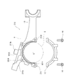
図10は、第2実施形態に係る軸箱本体211の図4相当の図である。図9及び10に示すように、軸箱本体211において、第1水平面S215及び第2水平面S216はいずれも、傾斜している支持面S214よりも下方に位置している。また、軸箱本体211では、第1実施形態に係る軸箱本体11と同様に、車幅方向外側の側面である第1側面S211のみに蓋15が取り付けられる。そのため、第1側面S211の第1座面部211dにネジ孔211fを形成するネジ孔加工が施され、車幅方向内側の側面である第2側面S212にはネジ孔加工は施されない。
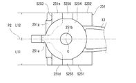
図11は、第2実施形態に係る軸箱原形物251の図7相当の図である。図11に示すように、軸箱原形物251は、第1実施形態の軸箱原形物51と同様に、収容空間Aの中心Cを基準に車幅方向に対称な形状に成形されている。具体的には、第1側面S251及び第2側面S252の両方に同じ輪郭を有する平坦な座面部251d,251eが形成されている。また、軸箱原形物251は、その上部のバネ座251aの車幅方向外側に、チャック用の第1水平面S215に対応する第1水平面S255を有しており、車幅方向内側に第1水平面S255と同じ形状の第2水平面S256を有している。更に、収容空間Aの車両長手方向外側の側面S253においても、排障器を取り付けるための受け座251gが収容空間Aの中心Cを基準にして車幅方向に対称な形状に成形されている。
即ち、本実施形態においても、鋳造工程では、左勝手の軸箱本体211と右勝手の軸箱本体211に関わらず、共通の軸箱原形物251が成形される。そして、第1実施形態で述べた機械加工を軸箱原形物251に施すことによって、軸箱本体211が形成される。
このような第2実施形態によっても第1実施形態と同様の効果が得られる。即ち、左勝手の軸箱本体と右勝手の軸箱本体を製造するにあたって、共通の軸箱原形物251を用いることが可能となる。そのため、軸箱原形物251の種類を低減できると共に、鋳型の共通化により鋳型費用を削減することができる。よって、左右一対の軸箱本体211を製造するにあたって、部品管理コスト及び製造コストを削減することができる。したがって、車幅方向に対称な形状の軸箱原形物251から製造される軸箱本体211は、一般的な台車枠3を備える台車1に限らず、板バネ209を用いた台車201においても適用可能である。
なお、本発明は前述した実施形態に限定されるものではなく、本発明の趣旨を逸脱しない範囲でその構成を変更、追加、又は削除することができる。前記各実施形態は互いに任意に組み合わせてもよく、例えば1つの実施形態中の一部の構成又は方法を他の実施形態に適用してもよい。また、実施形態中の一部の構成は、その実施形態中の他の構成から分離して任意に抽出可能である。前述の実施形態では、軸箱10,210は、車軸中心Oよりも下側の部分において軸箱本体11,211とカバー体12とに分割された構造であり、側面視において、軸箱本体11,211の内面S10が真円の一部をなす略半円形状を有していたが、この構成に限られない。例えば、側面視において、軸箱本体11,211の内面が真円形状を有していてもよい、即ち、軸受8が収容される収容空間Aが軸箱本体11,211の内面のみによって画定されてもよい。
1,201 鉄道車両用台車
6 車軸
8 軸受
10,210 軸箱
11,211 軸箱本体
11a,211a バネ座
11d,51d 第1座面部(座面部)
11e,51e 第2座面部(座面部)
11f 雌ネジ
11g,51g,251g 受け座
11h,51h 受け座
15 蓋
35 排障器
51,251 軸箱原形物
A 収容空間
S10,S50 内面
S11,S51 第1側面
S12,S52 第2側面
S15,S55 第1水平面
S16,S56 第2水平面
6 車軸
8 軸受
10,210 軸箱
11,211 軸箱本体
11a,211a バネ座
11d,51d 第1座面部(座面部)
11e,51e 第2座面部(座面部)
11f 雌ネジ
11g,51g,251g 受け座
11h,51h 受け座
15 蓋
35 排障器
51,251 軸箱原形物
A 収容空間
S10,S50 内面
S11,S51 第1側面
S12,S52 第2側面
S15,S55 第1水平面
S16,S56 第2水平面
Claims (8)
- 車軸を支持する軸受が収容される軸箱本体を備える軸箱を製造する方法であって、
前記軸受が収容される収容空間を有する軸箱原形物を鋳造により車幅方向に対称な形状に成形する鋳造工程と、
前記軸箱原形物を機械加工して前記軸箱本体を形成する加工工程と、を備える、鉄道車両用軸箱の製造方法。 - 前記鋳造工程では、前記軸箱原形物の車幅方向一方側の第1側面と車幅方向他方側の第2側面との両方に平坦な座面部を形成し、
前記加工工程では、前記第1側面又は前記第2側面の前記座面部に雌ネジを形成する、請求項1に記載の鉄道車両用軸箱の製造方法。 - 前記鋳造工程では、前記軸箱本体の車両長手方向外側の側面に、排障器が取り付けられる受け座を形成する、請求項1又は2に記載の鉄道車両用軸箱の製造方法。
- 前記鋳造工程では、前記軸箱本体の上部に、バネ座と、前記バネ座の車幅方向一方側に設けられたチャック用の第1水平面と、前記バネ座の車幅方向他方側に設けられたチャック用の第2水平面と、を形成する、請求項1乃至3のいずれか1項に記載の鉄道車両用軸箱の製造方法。
- 車軸を支持する軸受が収容される軸箱本体を備え、
前記軸箱本体は、
前記軸受が収容される収容空間を画定する内面と、
前記内面よりも外側で前記収容空間の中心に対して車幅方向一方側に設けられた第1側面と、
前記内面よりも外側で前記中心に対して車幅方向他方側に設けられた第2側面と、を有し、
車幅方向において、前記第1側面と前記中心との間の最短距離と、前記第2側面と前記中心との間の最短距離とが、互いに同一である、鉄道車両用軸箱。 - 前記第1側面に取り付けられ、前記収容空間を車幅方向一方側から閉じる蓋を更に備え、
前記第1側面には、前記蓋が取り付けられる平坦な座面部が形成され、
前記第2側面にも、前記座面部と同じ輪郭を有する座面部が形成されている、請求項5に記載の鉄道車両用軸箱。 - 前記軸箱本体は、その車両長手方向外側の側面において、排障器が取り付けられる受け座を有する、請求項5又は6に記載の鉄道車両用軸箱。
- 前記軸箱本体は、その上部に設けられたバネ座と、前記バネ座の車幅方向一方側に設けられたチャック用の第1水平面と、前記バネ座の車幅方向他方側に設けられたチャック用の第2水平面と、を有する、請求項5乃至7のいずれか1項に記載の鉄道車両用軸箱。
Priority Applications (2)
| Application Number | Priority Date | Filing Date | Title |
|---|---|---|---|
| CN201680075909.0A CN108367764B (zh) | 2015-12-25 | 2016-11-29 | 铁道车辆用轴箱以及该铁道车辆用轴箱的制造方法 |
| US16/065,978 US11136051B2 (en) | 2015-12-25 | 2016-11-29 | Railcar axle box and method of producing the same |
Applications Claiming Priority (2)
| Application Number | Priority Date | Filing Date | Title |
|---|---|---|---|
| JP2015-252982 | 2015-12-25 | ||
| JP2015252982A JP6595904B2 (ja) | 2015-12-25 | 2015-12-25 | 鉄道車両用軸箱及びその製造方法 |
Publications (1)
| Publication Number | Publication Date |
|---|---|
| WO2017110047A1 true WO2017110047A1 (ja) | 2017-06-29 |
Family
ID=59089909
Family Applications (1)
| Application Number | Title | Priority Date | Filing Date |
|---|---|---|---|
| PCT/JP2016/005007 Ceased WO2017110047A1 (ja) | 2015-12-25 | 2016-11-29 | 鉄道車両用軸箱及びその製造方法 |
Country Status (4)
| Country | Link |
|---|---|
| US (1) | US11136051B2 (ja) |
| JP (1) | JP6595904B2 (ja) |
| CN (1) | CN108367764B (ja) |
| WO (1) | WO2017110047A1 (ja) |
Families Citing this family (5)
| Publication number | Priority date | Publication date | Assignee | Title |
|---|---|---|---|---|
| JP6577834B2 (ja) * | 2015-10-29 | 2019-09-18 | 川崎重工業株式会社 | 鉄道車両用操舵台車 |
| JP6506676B2 (ja) * | 2015-10-29 | 2019-04-24 | 川崎重工業株式会社 | 鉄道車両用台車の軸箱支持装置 |
| JP6506677B2 (ja) * | 2015-10-29 | 2019-04-24 | 川崎重工業株式会社 | 鉄道車両用操舵台車 |
| JP6557595B2 (ja) * | 2015-12-25 | 2019-08-07 | 川崎重工業株式会社 | 鉄道車両用台車 |
| JP6595904B2 (ja) * | 2015-12-25 | 2019-10-23 | 川崎重工業株式会社 | 鉄道車両用軸箱及びその製造方法 |
Citations (5)
| Publication number | Priority date | Publication date | Assignee | Title |
|---|---|---|---|---|
| JP2003205840A (ja) * | 2002-01-16 | 2003-07-22 | Fuji Heavy Ind Ltd | 鉄道車両用軌間可変台車の排障器 |
| JP2006312987A (ja) * | 2005-05-09 | 2006-11-16 | Nsk Ltd | 車両用軸受装置 |
| JP2009202855A (ja) * | 2008-01-29 | 2009-09-10 | Nsk Ltd | 鉄道車両用軸受装置 |
| JP2012237337A (ja) * | 2011-05-10 | 2012-12-06 | Nsk Ltd | グリース密封封入転がり軸受 |
| JP2014037191A (ja) * | 2012-08-13 | 2014-02-27 | Kawasaki Heavy Ind Ltd | 鉄道車両用台車および軸ばね高さ調整システム |
Family Cites Families (14)
| Publication number | Priority date | Publication date | Assignee | Title |
|---|---|---|---|---|
| US2264249A (en) * | 1938-07-09 | 1941-11-25 | Magnus Metal Corp | Dam for journal bearings |
| US2690361A (en) * | 1951-03-17 | 1954-09-28 | American Steel Foundries | Journal box |
| US2833600A (en) * | 1955-05-02 | 1958-05-06 | Lee J Lyons | Railway axle journal bearing |
| US3363951A (en) * | 1965-04-29 | 1968-01-16 | Francis B. Rykoskey | Railway axle journal bearing with wear inserts |
| US3684331A (en) * | 1970-10-02 | 1972-08-15 | Hennessy Products | Railway axle journal stop |
| JPH10278791A (ja) | 1997-04-11 | 1998-10-20 | Kawasaki Heavy Ind Ltd | 分割型軸箱構造 |
| EP2058207B1 (en) * | 2003-07-08 | 2013-03-13 | National Steel Car Limited | Rail road car truck and members thereof |
| CN201109433Y (zh) * | 2007-07-06 | 2008-09-03 | 上海轨道交通设备发展有限公司 | 地铁车转向架上用的轴箱 |
| CN201151407Y (zh) * | 2007-12-28 | 2008-11-19 | 中国南车集团株洲车辆厂 | 铁路货车转向架用纵向弹性拉杆装置 |
| JP5118081B2 (ja) * | 2009-02-13 | 2013-01-16 | 川崎重工業株式会社 | 鉄道車両用軸箱支持装置 |
| JP6506564B2 (ja) * | 2015-02-04 | 2019-04-24 | 川崎重工業株式会社 | 鉄道車両用台車の板バネの状態監視装置 |
| JP6670098B2 (ja) * | 2015-12-25 | 2020-03-18 | 川崎重工業株式会社 | 鉄道車両用台車の軸箱支持装置及びその製造方法 |
| JP6595904B2 (ja) * | 2015-12-25 | 2019-10-23 | 川崎重工業株式会社 | 鉄道車両用軸箱及びその製造方法 |
| JP6803149B2 (ja) * | 2016-04-27 | 2020-12-23 | 川崎重工業株式会社 | 鉄道車両用台車の軸受温度検出装置 |
-
2015
- 2015-12-25 JP JP2015252982A patent/JP6595904B2/ja active Active
-
2016
- 2016-11-29 CN CN201680075909.0A patent/CN108367764B/zh active Active
- 2016-11-29 US US16/065,978 patent/US11136051B2/en active Active
- 2016-11-29 WO PCT/JP2016/005007 patent/WO2017110047A1/ja not_active Ceased
Patent Citations (5)
| Publication number | Priority date | Publication date | Assignee | Title |
|---|---|---|---|---|
| JP2003205840A (ja) * | 2002-01-16 | 2003-07-22 | Fuji Heavy Ind Ltd | 鉄道車両用軌間可変台車の排障器 |
| JP2006312987A (ja) * | 2005-05-09 | 2006-11-16 | Nsk Ltd | 車両用軸受装置 |
| JP2009202855A (ja) * | 2008-01-29 | 2009-09-10 | Nsk Ltd | 鉄道車両用軸受装置 |
| JP2012237337A (ja) * | 2011-05-10 | 2012-12-06 | Nsk Ltd | グリース密封封入転がり軸受 |
| JP2014037191A (ja) * | 2012-08-13 | 2014-02-27 | Kawasaki Heavy Ind Ltd | 鉄道車両用台車および軸ばね高さ調整システム |
Also Published As
| Publication number | Publication date |
|---|---|
| JP2017114364A (ja) | 2017-06-29 |
| CN108367764B (zh) | 2020-11-20 |
| JP6595904B2 (ja) | 2019-10-23 |
| US20190084596A1 (en) | 2019-03-21 |
| CN108367764A (zh) | 2018-08-03 |
| US11136051B2 (en) | 2021-10-05 |
Similar Documents
| Publication | Publication Date | Title |
|---|---|---|
| JP6595904B2 (ja) | 鉄道車両用軸箱及びその製造方法 | |
| JP5883488B2 (ja) | 鉄道車両用台車 | |
| TWI635008B (zh) | 鐵道車輛用台車之軸箱支承裝置及其製造方法 | |
| WO2014175414A1 (ja) | 車両のサブフレーム | |
| CN105857006B (zh) | 车轴总成及其制造方法、车辆平台和机动车 | |
| JP7065618B2 (ja) | 鉄道車両用台車 | |
| US9440490B2 (en) | Trailer axle repair kit having spare spindle and flange axle assembly | |
| CN105307925A (zh) | 机动车辆车桥的支架 | |
| WO2017110042A1 (ja) | 鉄道車両用台車 | |
| CN203344685U (zh) | 扭力梁后桥主梁 | |
| WO2011030405A1 (ja) | 自動車用ホイール | |
| JP6026288B2 (ja) | 鉄道車両用台車の軸箱支持装置 | |
| JP2013018342A (ja) | 鉄道車両用軸箱支持装置 | |
| CN106660390B (zh) | 车辆车轮的轮毂支撑件 | |
| US20190107159A1 (en) | Brake carrier and method of manufacture | |
| CN110216243A (zh) | 制动器夹钳壳体及其制造方法 | |
| CN1997543A (zh) | 用于座架定位于机动车车身上的定位构件、相应的座架和机动车 | |
| JP2018058507A (ja) | トラニオンブラケットおよびトラニオン式サスペンション | |
| JP2008179307A (ja) | 車両用ホイール | |
| US310778A (en) | Axle box and skein | |
| US1328195A (en) | Journal-bushing | |
| US1357266A (en) | Metal vehicle wheel | |
| US408240A (en) | johnson | |
| KR20160063457A (ko) | 철도용 축상스프링 구조 | |
| US1459992A (en) | Resilient wheel |
Legal Events
| Date | Code | Title | Description |
|---|---|---|---|
| 121 | Ep: the epo has been informed by wipo that ep was designated in this application |
Ref document number: 16877952 Country of ref document: EP Kind code of ref document: A1 |
|
| NENP | Non-entry into the national phase |
Ref country code: DE |
|
| 122 | Ep: pct application non-entry in european phase |
Ref document number: 16877952 Country of ref document: EP Kind code of ref document: A1 |