WO2017104460A1 - モータアクチュエータ - Google Patents
モータアクチュエータ Download PDFInfo
- Publication number
- WO2017104460A1 WO2017104460A1 PCT/JP2016/086032 JP2016086032W WO2017104460A1 WO 2017104460 A1 WO2017104460 A1 WO 2017104460A1 JP 2016086032 W JP2016086032 W JP 2016086032W WO 2017104460 A1 WO2017104460 A1 WO 2017104460A1
- Authority
- WO
- WIPO (PCT)
- Prior art keywords
- gear
- motor
- rotor
- poles
- transmission mechanism
- Prior art date
- Legal status (The legal status is an assumption and is not a legal conclusion. Google has not performed a legal analysis and makes no representation as to the accuracy of the status listed.)
- Ceased
Links
Images



Classifications
-
- H—ELECTRICITY
- H02—GENERATION; CONVERSION OR DISTRIBUTION OF ELECTRIC POWER
- H02K—DYNAMO-ELECTRIC MACHINES
- H02K1/00—Details of the magnetic circuit
- H02K1/06—Details of the magnetic circuit characterised by the shape, form or construction
- H02K1/08—Salient poles
- H02K1/10—Commutating poles
-
- H—ELECTRICITY
- H02—GENERATION; CONVERSION OR DISTRIBUTION OF ELECTRIC POWER
- H02K—DYNAMO-ELECTRIC MACHINES
- H02K1/00—Details of the magnetic circuit
- H02K1/06—Details of the magnetic circuit characterised by the shape, form or construction
- H02K1/12—Stationary parts of the magnetic circuit
- H02K1/14—Stator cores with salient poles
-
- H—ELECTRICITY
- H02—GENERATION; CONVERSION OR DISTRIBUTION OF ELECTRIC POWER
- H02K—DYNAMO-ELECTRIC MACHINES
- H02K7/00—Arrangements for handling mechanical energy structurally associated with dynamo-electric machines, e.g. structural association with mechanical driving motors or auxiliary dynamo-electric machines
- H02K7/10—Structural association with clutches, brakes, gears, pulleys or mechanical starters
Definitions
- the present invention relates to a motor actuator provided with a motor and a transmission mechanism.
- the actuator that drives the drain valve of the washing machine and the shutter of the ventilation fan is configured as a motor actuator that transmits the rotation of the AC synchronous motor by a transmission mechanism.
- the AC synchronous motor includes a rotor including a magnet in which S poles and N poles are alternately provided in the circumferential direction, and a stator core including a plurality of teeth facing the magnet in the radial direction.
- teeth of the same shape are arranged at equal angular intervals in the circumferential direction, the magnetic poles of the rotor and the teeth are completely opposed when the motor is stopped, and no rotational torque is generated when the motor is started. It becomes defective.
- a plurality of main poles are provided in the circumferential direction, and an auxiliary pole having a dimension in the circumferential direction (width dimension) of less than 1 ⁇ 2 times that of the main pole is provided between adjacent main poles in the circumferential direction.
- positioning structure is disclosed (refer patent document 1). According to such a configuration, the state in which the magnetic poles of the rotor and the teeth are completely opposed to each other can be eliminated by supplementary poles. Therefore, rotational torque can be generated at the time of starting the motor, so that starting failure is unlikely to occur. .
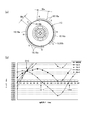
- the number of magnetic poles of the rotor 15 is 8 poles in total including the N pole and the S pole, and the width dimension Wb of the auxiliary pole 18b is less than 1 ⁇ 2 times the main pole 18a.
- the result shown in FIG. 9B is obtained.
- a stable point O11 appears at an angular position of 17.5 ° in the rotational angle of the rotor 15, and an unstable point O12 appears at an angular position of 38.75 ° in the rotational angle of the rotor 15. To do.
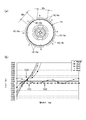
- the width dimension Wb of the auxiliary pole 18b was examined to be expanded to a dimension exceeding 3/4 times the main pole 18a.
- the result shown in FIG. 10B is obtained.
- a stable point O21 appears at an angular position of 9.075 ° in the rotational angle of the rotor 15, and an unstable point O22 appears at an angular position of 20.45 ° in the rotational angle of the rotor 15. did.
- the angular position (dead point D20) at which the torque does not change when excited is deviated by only 2 ° from the stable point O21.
- the width dimension Wb of the auxiliary pole 18b is set to a dimension exceeding 3/4 times the main pole 18a, the detent torque is small. For this reason, if a load is applied to the rotor 15 from the outside when the motor is stopped, the rotor 15 may stop at the dead point D20. Accordingly, when a load is applied to the rotor 15 by an external force or an internal resistance and the torque and the load are balanced, the motor cannot be started.
- the rotation angle of the rotor 15 corresponds to an electrical angle ⁇ (45/180).
- the stable point is a position at which the teeth 18 and the magnetic poles of the rotor 15 are completely opposed to each other and is very stable. Therefore, if the external force applied to the rotor 15 is zero, the rotor 15 is always Stop at this place.
- the unstable point is a position deviated by 1/2 pitch from the stable point and is a very unstable state. Therefore, when an external force is applied to the rotor 15 even a little, the rotor 15 is either clockwise or counterclockwise. Move to the stable point.
- the dead point is the position of the rotor 15 where no torque change occurs regardless of the increase or decrease of the magnetic force during teeth excitation.
- an object of the present invention is to provide a motor actuator that can suppress both a motor start failure and a rotor vibration.
- the present invention provides a motor actuator having an AC synchronous motor and a transmission mechanism for transmitting the output of the AC synchronous motor, wherein the AC synchronous motor has an S pole in the circumferential direction. And a stator core having a plurality of teeth opposed to the magnet in the radial direction, and the plurality of teeth are arranged in the circumferential direction.
- a plurality of main poles and an auxiliary pole disposed between the main poles adjacent in the circumferential direction and having a width dimension that is a dimension in the circumferential direction smaller than the main pole, and the width dimension of the auxiliary pole Is wider than 1 ⁇ 2 times the width dimension of the main pole and narrower than 3/4 times the width dimension of the main pole.
- the width dimension of the auxiliary pole is narrower than 3/4 times the width dimension of the main pole, the stable point and the dead point can be sufficiently separated. Therefore, the motor can be started properly.
- the width of the auxiliary pole is wider than half the width of the main pole, fluctuations in torque due to magnetic attraction and repulsion when the rotor magnetic pole jumps between the teeth can be suppressed. The vibration of the rotor can be suppressed. Therefore, according to the present invention, it is possible to suppress both startup failure and rotor vibration.
- the auxiliary pole is located between the main poles adjacent in the circumferential direction and the main pole located on the opposite side to the rotation direction of the rotor is located on the rotation direction side of the rotor. It is preferable that the distance from the main electrode is narrower. According to such a configuration, it is possible to suppress fluctuations in torque caused by the attraction and repulsion of the magnetic poles when the magnetic poles of the rotor jump over the teeth, so that vibrations of the rotor can be suppressed. Therefore, stability when the rotor rotates can be enhanced.
- the complementary poles are evenly arranged and point-symmetrically about the rotation center axis. According to such a configuration, the magnetic balance between the rotor and the stator is good.
- the present invention it is possible to adopt a mode in which the complementary poles are arranged at two point-symmetrical positions around the rotation center axis. According to such a configuration, since the minimum number of supplementary poles necessary for suppressing start-up failure is provided, it is possible to suppress fluctuations in torque caused by the magnetic pole attracting and repelling when the magnetic pole of the rotor jumps between the teeth. Therefore, vibration of the rotor can be suppressed.
- the main poles are arranged at six places, and the complementary poles are arranged at every three main poles arranged continuously at equal intervals in the circumferential direction.
- the present invention is effective when applied to a case where the transmission mechanism includes a mechanism for applying a load for rotating the rotor during a period in which energization of the motor is stopped. If the transmission mechanism includes a mechanism that applies a load that rotates the rotor while the motor is de-energized, the rotor cannot withstand the load when it approaches the dead point during startup. It is easy to cause problems such as defects, and problems that start-up defects occur when a rotor that has stopped at a stable point rotates to a dead point due to a load.According to the present invention, the occurrence of such problems is suppressed. can do.
- the transmission mechanism includes a first transmission mechanism that transmits the power of the motor to a mechanism that applies the load, and a clutch unit that switches the power of the first transmission mechanism to a connected state or a disconnected state. And a second transmission mechanism for transmitting the power of the motor to the clutch means.
- the mechanism for applying the load is a valve body that opens and closes a drain port of the washing machine.
- the width dimension of the auxiliary pole is narrower than 3/4 times the width dimension of the main pole, the stable point and the dead point can be sufficiently separated. Therefore, the motor can be started properly.
- the width of the auxiliary pole is wider than half the width of the main pole, fluctuations in torque due to magnetic attraction and repulsion when the rotor magnetic pole jumps between the teeth can be suppressed. The vibration of the rotor can be suppressed. Therefore, according to the present invention, it is possible to suppress both startup failure and rotor vibration.
- upper and lower means the upper and lower in FIG.
- original position refers to the position of each constituent member in a state where the motor 10 is not driven.
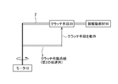
- FIG. 1 is an explanatory diagram showing a power system in a motor actuator 1 to which the present invention is applied.
- the power system of the motor actuator 1 includes a first transmission mechanism 2 that transmits the power of the motor 10 to the driven member 90 and a second transmission mechanism 3 that operates the clutch means 30.
- the clutch means 30 switches the transmission of power by the first transmission mechanism 2 to a connected state or a disconnected state. If the clutch means 30 is in the joint state, the power of the motor 10 is transmitted to the driven member 90. If the clutch means 30 is in the disconnected state, the power of the motor 10 is not transmitted to the driven member 90. In this embodiment, a part of the power of the motor 10 is used as the power for operating the clutch means 30.
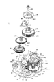
- FIG. 2 is a perspective view showing a main part of the motor actuator 1 to which the present invention is applied.
- FIG. 3 is an exploded perspective view of a main part of the motor actuator 1 to which the present invention is applied.
- FIG. 4 is an exploded perspective view of the clutch means 30 shown in FIG.
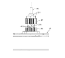
- FIG. 5 is an explanatory diagram of the clutch pinion 21 and the motor pinion 41 in the motor actuator 1 to which the present invention is applied.
- FIG. 6 is an explanatory diagram of the lock lever 44 and the like disposed below the driven gear 43 shown in FIG.
- the motor actuator 1 includes a motor 10 that is a drive source, a first transmission mechanism 2 that transmits power of the motor 10 to the driven member 90, and power of the first transmission mechanism 2.
- the clutch means 30 that switches the transmission to the connected state or the disconnected state, the second transmission mechanism 3 that transmits the power of the motor 10 to the clutch means 30, and the load applying means 50 that applies a load to the driven gear 43 are provided.
- the motor 10, the first transmission mechanism 2, the clutch means 30, the second transmission mechanism 3, and the load applying means 50 are all housed in a case (not shown).
- the motor 10 is an AC synchronous motor, and the detailed configuration of the motor 10 will be described later with reference to FIG.
- FIG. 4 is an exploded perspective view of the clutch means 30 shown in FIG.
- FIG. 5 is an explanatory diagram of the clutch pinion 21 and the motor pinion 41 in the motor actuator 1 to which the present invention is applied.
- FIG. 6 is an explanatory diagram of the lock lever 44 and the like disposed below the driven gear 43 shown in FIG.
- the 1st transmission mechanism 2 comprises the output system which transmits the motive power of the motor 10 to the driven member 90 (refer FIG. 3).
- the first transmission mechanism 2 includes a clutch pinion 21, an input side gear 22 meshing with the clutch pinion 21, and an output side gear 23 that rotates with the rotation of the input side gear 22 when the clutch means 30 is in the connected state (see FIG.
- a composite gear 24 that meshes with the output gear 23, a cam gear 25 that meshes with the composite gear 24, and a pulley 26 that rotates integrally with the cam gear 25.
- a wire 27 (see FIG. 3) to which a driven member 90 is connected is wound around the pulley 26.
- the input side gear 22 and the output side gear 23 constitute the clutch means 30.
- the clutch pinion 21 is a spur gear supported on the support shaft 150 of the motor 10 so as to be rotatable and movable in the axial direction.
- a locked projection 211 is formed on the upper surface of the clutch pinion 21.
- the sector lever 60 acts on the locked projection 211.
- the clutch pinion 21 is biased upward by a coil spring (not shown).
- An upper engaging portion 215 (see FIG. 5) that engages with the motor pinion 41 is formed on the lower surface of the clutch pinion 21.
- the input side gear 22 meshes with the clutch pinion 21.
- the input side gear 22 is a sun gear that constitutes a planetary gear mechanism.
- the input-side gear 22 includes a large-diameter large-diameter gear 221 and a small-diameter gear (not shown) formed smaller in diameter than the large-diameter gear 221 inside the large-diameter gear 221.
- the large-diameter gear 221 meshes with the clutch pinion 21, and the input-side gear 22 rotates as the clutch pinion 21 rotates.
- the output side gear 23 includes three planetary gears 231 and a planetary support gear 232 that rotatably supports the planetary gear 231, and the planetary gear 231 is an upper end surface of the planetary support gear 232. And the retaining ring 233 are provided at equiangular intervals.
- the planetary support gear 232 has a gear portion 2321 on the side opposite to the side that supports the planetary gear 231.
- the planetary gear 231 meshes with the small-diameter gear of the input-side gear 22 and revolves around the small-diameter gear of the input-side gear 22 when the clutch means 30 is in the joint state. Further, when the planetary gear 231 revolves, the planetary support gear 232 rotates and power is transmitted from the input side gear 22 to the output side gear 23.
- the compound gear 24 is engaged with the planetary support gear 232.
- the compound gear 24 includes a small-diameter gear 241 and a large-diameter gear 242 having a larger diameter than the small-diameter gear 241, and the large-diameter gear 242 meshes with the gear portion 2321 of the planetary support gear 232. Therefore, when the planetary support gear 232 rotates, the compound gear 24 rotates.
- the gear portion 251 of the cam gear 25 meshes with the small diameter gear 241 of the compound gear 24. Therefore, when the compound gear 24 rotates, the cam gear 25 rotates.
- a cam groove 252 is formed on the upper end surface of the disc portion where the gear portion 251 is formed. A fan-shaped lever 60 described later is engaged with the cam groove 252.
- the pulley 26 is fixed to the cam gear 25 by a bolt 269. Accordingly, when the cam gear 25 rotates, the pulley 26 rotates. One end of a wire 27 is fixed to the pulley 26. Therefore, when the pulley 26 rotates in the direction in which the wire 27 is drawn, the wire 27 is wound around the pulley 26.
- a driven member 90 (for example, a valve body that opens and closes a drain port) is fixed to the other end side of the wire 27, and the driven member 90 is always in its original position (valve body as indicated by an arrow F). The load in the direction (the direction in which the wire 27 is pulled out) to return to the position where the is closed) is acting.
- the second transmission mechanism 3 constitutes a clutch operating system that transmits the power of the motor 10 to the clutch means 30.
- the second transmission mechanism 3 includes a motor pinion 41, a driving gear 42 that meshes with the motor pinion 41, a driven gear 43 that meshes with the driving gear 42, and a lock lever 44 that is pushed down when the driven gear 43 moves downward. (See FIG. 6), and a lock gear 46 that is locked when the lock lever 44 is pushed down.
- the motor pinion 41 is a spur gear formed integrally with the rotor 15 of the motor 10. On the upper surface of the motor pinion 41, a lower engagement portion 415 (see FIG.
- the drive side gear 42 meshes with the motor pinion 41.
- the driving gear 42 is supported by the support shaft 427 so as to be rotatable and movable in the axial direction.
- the driving gear 42 includes a large-diameter gear 421 and a small-diameter gear 422 having a smaller diameter than the large-diameter gear 421.
- the small-diameter gear 422 has helical teeth.
- the drive side gear 42 has a large diameter gear 421 meshing with the motor pinion 41.
- the driven side gear 43 meshes with the driving side gear 42, and the driven side gear 43 is rotatably supported by the support shaft 437.
- the driven gear 43 includes a large diameter gear 432 and a small diameter gear 431 having a smaller diameter than the large diameter gear 432. Both the large diameter gear 432 and the small diameter gear 431 are formed with helical teeth.
- the large diameter gear 432 is engaged with the small diameter gear 422 of the drive side gear 42. Therefore, the driven gear 43 rotates as the driving gear 42 rotates. At that time, a downward thrust load is generated on the driven gear 43 because a load in the direction opposite to the rotation direction is applied by the load applying means 50 described later. Therefore, when the drive side gear 42 rotates, the driven side gear 43 moves downward while rotating.
- the lock lever 44 is a flat plate-like member, and is supported by a support shaft 437 so as to be movable in the axial direction below the driven gear 43.
- a concave portion 442 is formed at one end of the lock lever 44, and the concave portion 442 is engaged with a convex portion (not shown) extending in the axial direction in a case (not shown). For this reason, the lock lever 44 is prevented from rotating.
- a convex lock portion 441 is formed at the other end of the lock lever 44.
- a biasing member (not shown) for biasing the lock lever 44 upward is disposed below the lock lever 44. When the motor 10 is stopped by the biasing member, the lock lever 44 is It is located above the locked portion 461 of the lock gear 46.
- the driven gear 43 is disposed on the lock lever 44, the driven gear 43 is also biased upward.
- the urging force of the urging member is smaller than the downward thrust load generated in the driven gear 43 when the driven gear 43 rotates as the driving gear 42 rotates. Therefore, when the driven gear 43 rotates, the driven gear 43 moves downward against the biasing force of the biasing member. As a result, the lock lever 44 also moves downward, so that the lock portion 441 of the lock lever 44 moves to substantially the same height as the locked portion 461 of the lock gear 46.
- the lock gear 46 includes a disc portion 463 and a gear 462 formed above the disc portion 463, and the locked portion 461 protrudes outward from the disc portion 463. Therefore, when the lock lever 44 moves downward, the lock portion 441 and the locked portion 461 interfere with each other, and the rotation of the lock gear 46 is prevented.
- the lock gear 46 meshes with the external gear 311 of the fixed gear 31. Therefore, when the rotation of the lock gear 46 is blocked, the rotation of the fixed gear 31 is also blocked.
- the lock gear 46 has a brake portion 464 that is a centrifugal brake. The brake unit 464 applies a load in a direction that hinders the rotation of the lock gear 46, and prevents the lock gear 46 from rotating at a higher speed than necessary.
- the load applying means 50 is configured to apply a load in the direction opposite to the rotation direction to the driven gear 43, and includes a gear 51 made of a worm gear and a load portion 52 made of a centrifugal brake.
- the gear 51 extends in a direction orthogonal to the axial direction of the driven gear 43 and meshes with the large-diameter gear 432.
- the large-diameter gear 432 and the gear 51 constitute a speed increasing gear mechanism. Accordingly, the rotation of the driven gear 43 is increased and transmitted to the gear 51.
- the load unit 52 is a governor that increases the load generated in the direction of stopping the rotation when the rotation speed increases.
- the driven gear 43 When the rotational speed of the driven gear 43 is increased by the load portion 52, the load received in the direction to stop the rotation increases. As the load of the load portion 52 increases, the driven gear 43 that meshes with the driving gear 42 receives the downward thrust load. Further, the driven gear 43 receives a downward thrust load also by the meshing of the large diameter gear 432 and the gear 51. At this time, when the downward thrust load received by the driven gear 43 becomes larger than the upward biasing force of the biasing member, the driven gear 43 is subjected to a load in the direction opposite to the rotation direction by the load portion 52. It moves downward by meshing.
- the sector lever 60 is disposed on the compound gear 24.
- the sector lever 60 is rotatably supported by the support shaft 247 as in the compound gear 24.
- An engaging protrusion 61 is formed on the lower surface of the sector lever 60.
- the engaging protrusion 61 is engaged with a cam groove 252 formed on the upper surface of the cam gear 25.
- a lock protrusion and an inclined cam are formed on the lower surface of the sector lever 60.
- the clutch pinion 21 is rotated together with the motor pinion 41 by driving the motor 10, the input side gear 22 is rotated and the planetary gear 231 is revolved, so that the planetary support gear 232 is rotated. Therefore, the rotational power of the input side gear 22 is transmitted to the output side gear 23.
- the large-diameter gear 242 of the compound gear 24 meshes with the gear portion 2321 of the planetary support gear 232. Therefore, the compound gear 24 rotates as the planetary support gear 232 rotates.
- the gear portion 251 of the cam gear 25 is meshed with the small diameter gear 241 of the compound gear 24. Therefore, the cam gear 25 rotates as the compound gear 24 rotates.
- the driven member 90 is fixed to the tip of the wire 27, the driven member 90 operates to be pulled up by the wire 27.
- the driven member 90 is a valve body that opens and closes the drain port of the washing machine, the drain port is opened when the valve body is pulled up by the wire 27, and drainage is started.
- the winding of the wire 27 by the pulley 26 is stopped as follows. First, when the cam gear 25 rotates to a predetermined position, the sector lever 60 having the engaging protrusion 61 that engages with the cam groove 252 rotates in a direction away from the cam gear 25. As a result, the locking projection of the sector lever 60 contacts the locked projection 211 of the clutch pinion 21 from the circumferential direction. As a result, the clutch pinion 21 is prevented from rotating. Further, the clutch pinion 21 pressed downward in the axial direction by the inclined cam of the sector lever 60 is released and moves upward.
- the driven member 90 is always going to return to the original position by an external load acting on itself.
- the driven member 90 is a valve body that opens and closes the drain port of the washing machine, and the valve body is operated in a direction to open the drain port by driving the motor actuator 1, the valve body always opens the drain port. It is biased in the closing direction. Therefore, when the clutch means 30 is in the disconnected state, the load applied to the driven member 90 is transmitted to the planetary support gear 232 of the output side gear 23 so as to reverse the first transmission mechanism 2. The energy based on the load applied to the driven member 90 thus transmitted is consumed by idling of the output side gear 23 because the clutch means 30 is in the disengaged state. Thereby, the driven member 90 returns to the original position.
- the sector lever 60 having the engagement protrusion 61 that engages with the cam groove 252 rotates in a direction approaching the cam gear 25.
- the sector lever 60 rotates in this way, the locking projection 62 of the sector lever 60 is separated from the locked projection 211 of the clutch pinion 21.
- the clutch pinion 21 is allowed to rotate.
- the clutch pinion 21 urged upward in the axial direction by the coil spring is pressed against the inclined cam and moves downward. Accordingly, the upper engagement portion 215 of the clutch pinion 21 and the lower engagement portion 415 of the motor pinion 41 are engaged, and the power of the motor 10 is transmitted to the clutch pinion 21.
- the brake portion 464 of the lock gear 46 brakes the operation of the driven member 90 to return to the original position, and softens the impact applied to the first transmission mechanism 2. Therefore, damage to the power transmission member constituting the first transmission mechanism 2 can be prevented.
- the driven member 90 returns to the original position, an impact sound that collides with each other (when the driven member 90 is a valve body that opens and closes the drain port of the washing machine, the valve body is (Impact sound that collides with the surroundings) can be reduced.
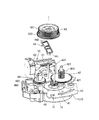
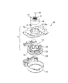
- FIG. 7 is an exploded perspective view of the motor 10 used in the motor actuator 1 to which the present invention is applied.
- the motor 10 includes a rotor 15 that is rotatably supported by a support shaft 150 and a stator 11, and the rotor 15 includes a cylindrical magnet 14.
- the stator 11 includes a plate-shaped stator core 12 including a plurality of teeth 18 that face the magnet 14 on the outer side in the radial direction, and an insulator 13 that holds the stator core 12.
- the teeth 18 are cylindrical in shape of the insulator 13. It is positioned so as to be along the inner peripheral surface of the body portion 130 of the body.
- the insulator 13 has flange portions 131 and 132 on both sides of the body portion 130, and the coil wire 19 is wound around the body portion 130 between the flange portions 131 and 132.
- the stator 11 thus configured is covered with a cover 16, and the cover 16 and the insulator 13 are connected.
- the stator core 12 is provided with teeth 18 having a configuration described with reference to FIG.
- FIG. 8 is an explanatory diagram of the teeth 18 of the motor 10 of the motor actuator 1 to which the present invention is applied.
- FIGS. 8A and 8B are plan views of the teeth 18 and an explanation showing the magnetic field analysis result at that time.
- FIG. 8A and 8B are plan views of the teeth 18 and an explanation showing the magnetic field analysis result at that time.
- the plurality of teeth 18 include a plurality of main poles 18a arranged in the circumferential direction, and between the main poles 18a adjacent in the circumferential direction. Includes a complementary pole 18b having a width dimension smaller than that of the main pole 18a in the circumferential direction.
- the number of magnetic poles of the rotor 15 is 8 poles in total including the N pole and the S pole, and the main pole 18a has three main poles 18a at equal intervals in each of two regions separated in the circumferential direction.
- the complementary poles 18b are arranged evenly and symmetrically with respect to the rotation center axis L.
- the complementary poles 18b are arranged at positions adjacent to each other in the clockwise direction CW in two regions where the three main poles 18a are arranged at equal intervals. They are arranged point-symmetrically around the rotation center axis L.
- the rotor 15 rotates clockwise CW
- the auxiliary pole 18b is positioned on the opposite side to the rotation direction of the rotor 15 between the main poles 18a adjacent in the circumferential direction.
- the distance from the main pole 18a is narrower than the distance from the main pole 18a located on the rotation direction side of the rotor 15. That is, the main poles 18a are arranged at six places, and the auxiliary poles 18b are arranged at every three main poles 18a arranged continuously at equal intervals in the circumferential direction.
- a stable point O31 appears at an angular position of 21.25 ° with respect to the rotational angle of the rotor 15, and an unstable point O32 appears at an angular position of 41.25 ° with respect to the rotational angle of the rotor 15. Further, the angular position (dead point D30) at which the torque does not change when excited is deviated by 15 ° from the stable point O31 by the rotation angle of the rotor 15.
- the width dimension Wb of the auxiliary pole 18b is wider than 1 ⁇ 2 times the width dimension Wa of the main pole 18a. Since it is narrower than twice, the detent torque is at an appropriate level. Further, since the width dimension Wb of the auxiliary pole 18b is smaller than 3/4 times the width dimension Wa of the main pole 18a, the stable point O31 and the dead point D30 can be sufficiently separated. Therefore, since the rotor 15 is difficult to stop at the dead point D30, the motor 10 can be started appropriately.
- the width dimension Wb of the auxiliary pole 18b is larger than 1 ⁇ 2 times the width dimension Wa of the main pole 18a, the fluctuation of the torque due to the attraction and repulsion of the magnetic pole when the magnetic pole of the rotor 15 jumps between the teeth 18 Therefore, vibration of the rotor 15 can be suppressed. Therefore, both the starting failure and the vibration of the rotor 15 can be suppressed.
- the interval between the auxiliary pole 18 b and the main pole 18 a located on the opposite side of the rotation direction of the rotor 15 (clockwise CW direction) between the main poles 18 a adjacent in the circumferential direction is the rotation of the rotor 15. It is narrower than the distance to the main pole 18a located on the direction (clockwise CW direction) side. For this reason, the fluctuation
- the complement poles 18b are arranged evenly and point-symmetrically about the rotation center axis L, the magnetic balance between the rotor 15 and the stator 11 is good.
- the complementary poles 18b are arranged at two point-symmetrical points with the rotation center axis L as the center. For this reason, since the minimum auxiliary pole 18b necessary for suppressing the start-up failure is provided, it is possible to suppress the torque fluctuation caused by the magnetic pole attracting and repelling when the magnetic pole of the rotor 15 jumps between the teeth 18. Therefore, since vibration of the rotor 15 can be suppressed, stability when the rotor 15 rotates can be improved.
- the width dimension Wb of the auxiliary pole 18b is wider than 1 ⁇ 2 times the width dimension Wa of the main pole 18a, and narrower than 3/4 times the width dimension Wa of the main pole 18a.
- the auxiliary pole 18b is provided at an angular position that is 180 ° apart.
- the auxiliary pole 18b may be provided at an adjacent position.
- the two complementary poles 18b are provided.
- the complementary poles 18b may be provided at one place or at three or more places.
- the number of magnetic poles of the rotor 15 is 8 poles including the N pole and the S pole, but the present invention may be applied to other poles.
Landscapes
- Engineering & Computer Science (AREA)
- Power Engineering (AREA)
- Connection Of Motors, Electrical Generators, Mechanical Devices, And The Like (AREA)
- Iron Core Of Rotating Electric Machines (AREA)
Abstract
モータの起動不良およびロータの振動の双方を抑制することのできるモータアクチュエータを提供すること。具体的には、流同期モータからなるモータ10と、モータ10の出力を伝達する伝達機構とを有するモータアクチュエータにおいて、モータ10は、周方向にS極とN極とが交互に設けられた磁石14を備えたロータ15と、磁石14と径方向で対向する複数のティース18を備えたステータコア12とを有している。複数のティース18には、周方向に配置された複数の主極18aと、周方向で隣り合う主極18aの間に配置された補極18bとが含まれ、補極18bの幅寸法Wbは、主極18aの幅寸法Waの1/2倍より広く、主極18aの幅寸法Waの3/4倍より狭い。
Description
本発明は、モータおよび伝達機構を備えたモータアクチュエータに関するものである。
洗濯機の排水弁や換気扇のシャッタを駆動するアクチュエータは、交流同期モータの回転を伝達機構によって伝達するモータアクチュエータとして構成されている。交流同期モータは、周方向にS極とN極とが交互に設けられた磁石を備えたロータと、磁石と径方向で対向する複数のティースを備えたステータコアとを有している。ここで、同一形状のティースを周方向に等角度間隔に配置すると、モータの停止時に、ロータの磁極とティースとが完全に対向してしまい、モータの起動時、回転トルクが発生せず、起動不良となってしまう。
一方、複数のティースとして、周方向に複数の主極を設けるとともに、周方向で隣り合う主極の間に、周方向における寸法(幅寸法)が主極の1/2倍未満の補極を配置した構成が開示されている(特許文献1参照)。かかる構成によれば、ロータの磁極とティースとが完全に対向する状態を補極によって解消することができるので、モータの起動時、回転トルクを発生させることができるので、起動不良が発生しにくい。
具体的には、図9(a)に示すように、ロータ15の磁極の数がN極およびS極合わせて8極で、補極18bの幅寸法Wbが主極18aの1/2倍未満である場合、無励磁時、および10mA~40mAの定電流を印加した場合の磁場解析を行うと、図9(b)に示す結果となる。図9(b)からわかるように、ロータ15の回転角で17.5°の角度位置に安定点O11が出現し、ロータ15の回転角で38.75°の角度位置に不安定点O12が出現する。
しかしながら、特許文献1に記載の構成のように、補極18bの幅寸法Wbが主極18aの1/2倍未満である場合、ディテントトルクが大きいため、ロータ15の磁極がティース18の間を飛び越える際の磁極の吸引と反発に起因するトルクの変動が大きく、ロータ15に振動が発生するという問題点がある。
そこで、補極18bの幅寸法Wbを、図10(a)に示すように、例えば主極18aの3/4倍を超える寸法まで拡大することを検討した。かかる構成を採用した場合の磁場解析を行うと、図10(b)に示す結果となる。図10(b)からわかるように、ロータ15の回転角で9.075°の角度位置に安定点O21が出現し、ロータ15の回転角で20.45°の角度位置に不安定点O22が出現した。また、励磁した際、トルクが変化しない角度位置(デッドポイントD20)は、安定点O21から2°しかずれていない。また、補極18bの幅寸法Wbを主極18aの3/4倍を超える寸法に設定すると、ディテントトルクが小である。このため、モータの停止時にロータ15に外部から負荷が加わると、ロータ15がデッドポイントD20で停止するおそれがある。従って、外力や内部抵抗によりロータ15に負荷が加わり、上記のトルクと負荷とがつり合った場合、モータは起動不可となる。
なお、ロータ15の回転角は、電気角×(45/180)に相当する。安定点とは、ティース18とロータ15の磁極とが完全に相対した位置で停止している位置であり、非常に安定しているため、ロータ15に加わる外力を0にすると、ロータ15は必ずこの場所で停止する。不安定点とは、安定点から1/2ピッチずれた位置であり、非常に不安定な状態であるため、ロータ15に外力が少しでも加わると、ロータ15は時計周りあるいは反時計周りのどちらかの安定点に移動する。デッドポイントとは、ティース励磁時の磁力増減に関わらず、トルク変化が発生しないロータ15の位置である。
以上の問題点に鑑みて、本発明の課題は、モータの起動不良およびロータの振動の双方を抑制することのできるモータアクチュエータを提供することにある。
上記課題を解決するために、本発明は、交流同期モータと、前記交流同期モータの出力を伝達する伝達機構と、を有しているモータアクチュエータにおいて、前記交流同期モータは、周方向にS極とN極とが交互に設けられた磁石を備えたロータと、前記磁石と径方向で対向する複数のティースを備えたステータコアと、を有し、前記複数のティースには、周方向に配置された複数の主極と、周方向で隣り合う前記主極の間に配置され、周方向における寸法である幅寸法が前記主極より小の補極と、が含まれ、前記補極の幅寸法は、前記主極の幅寸法の1/2倍より広く、前記主極の幅寸法の3/4倍より狭いことを特徴とする。
本発明では、補極の幅寸法が主極の幅寸法の3/4倍より狭いため、安定点とデッドポイントとを十分に離間させることができる。従って、モータを適正に起動させることができる。また、補極の幅寸法が主極の幅寸法の1/2倍より広いため、ロータの磁極がティースの間を飛び越える際の磁極の吸引と反発に起因するトルクの変動を抑えることができるので、ロータの振動を抑制することができる。それ故、本発明によれば、起動不良およびロータの振動の双方を抑制することができる。
本発明において、前記補極は、周方向で隣り合う前記主極の間のうち、前記ロータの回転方向とは逆側に位置する前記主極との間隔が前記ロータの回転方向側に位置する前記主極との間隔より狭いことが好ましい。かかる構成によれば、ロータの磁極がティースの間を飛び越える際の磁極の吸引と反発に起因するトルクの変動を抑えることができるので、ロータの振動を抑制することができる。それ故、ロータが回転する際の安定性を高めることができる。
本発明において、前記補極は、偶数、かつ、回転中心軸線を中心とする点対称に配置されていることが好ましい。かかる構成によれば、ロータとステータとの間の磁気バランスがよい。
本発明において、前記補極は、回転中心軸線を中心とする点対称な2個所に配置されている態様を採用することができる。かかる構成によれば、起動不良の抑制に必要な最小限の補極を設けたため、ロータの磁極がティースの間を飛び越える際の磁極の吸引と反発に起因するトルクの変動を抑えることができる。それ故、ロータの振動を抑制することができる。また、本発明において、前記主極は、6箇所に配置され、周方向へ等間隔に連続して配置される主極3箇所ごとに前記補極が配置されていることが好ましい。
本発明は、前記伝達機構が、前記モータへの通電を停止している期間に前記ロータを回転させる負荷を印加する機構を含んでいる場合に適用すると効果的である。伝達機構が、モータへの通電を停止している期間にロータを回転させる負荷を印加する機構を含んでいる場合には、起動時にロータがデッドポイントに接近した際に負荷に耐えきれずに起動不良が発生するという問題や、安定点で停止していたロータが負荷によってデッドポイントまで回転して起動不良が発生するという問題が発生しやすいが、本発明によれば、かかる問題の発生を抑制することができる。また、本発明において、前記伝達機構は、前記モータの動力を前記負荷を印加する機構に伝達する第1伝達機構と、前記第1伝達機構による動力を継状態もしくは断状態に切り替えるクラッチ手段と、前記モータの動力を前記クラッチ手段に伝達する第2伝達機構と、を含んでいることが好ましい。さらに、本発明において、前記負荷を印加する機構は、洗濯機の排水口を開閉する弁体であることが好ましい。
本発明では、補極の幅寸法が主極の幅寸法の3/4倍より狭いため、安定点とデッドポイントとを十分に離間させることができる。従って、モータを適正に起動させることができる。また、補極の幅寸法が主極の幅寸法の1/2倍より広いため、ロータの磁極がティースの間を飛び越える際の磁極の吸引と反発に起因するトルクの変動を抑えることができるので、ロータの振動を抑制することができる。それ故、本発明によれば、起動不良およびロータの振動の双方を抑制することができる。
以下、本発明の実施形態について詳細に説明する。なお、以下の説明における「上下」については、便宜上、図1等における上下をいうものとする。また、「原位置」とは、モータ10が駆動していない状態における各構成部材の位置をいう。
(モータアクチュエータ1の全体構成)
図1は、本発明を適用したモータアクチュエータ1における動力系統を示す説明図である。図1に示すように、モータアクチュエータ1の動力系統は、モータ10の動力を被駆動部材90に伝達する第1伝達機構2と、クラッチ手段30を動作させる第2伝達機構3とからなる。クラッチ手段30は、第1伝達機構2による動力の伝達を継状態もしくは断状態に切り替える。クラッチ手段30が継状態であれば、モータ10の動力は被駆動部材90に伝達される。クラッチ手段30が断状態であれば、モータ10の動力は被駆動部材90に伝達されない。本形態では、クラッチ手段30を動作させる動力としてモータ10の動力の一部を利用する。
図1は、本発明を適用したモータアクチュエータ1における動力系統を示す説明図である。図1に示すように、モータアクチュエータ1の動力系統は、モータ10の動力を被駆動部材90に伝達する第1伝達機構2と、クラッチ手段30を動作させる第2伝達機構3とからなる。クラッチ手段30は、第1伝達機構2による動力の伝達を継状態もしくは断状態に切り替える。クラッチ手段30が継状態であれば、モータ10の動力は被駆動部材90に伝達される。クラッチ手段30が断状態であれば、モータ10の動力は被駆動部材90に伝達されない。本形態では、クラッチ手段30を動作させる動力としてモータ10の動力の一部を利用する。
(モータアクチュエータ1の具体的構成例)
図2は、本発明を適用したモータアクチュエータ1の要部を示す斜視図である。図3は、本発明を適用したモータアクチュエータ1の要部の分解斜視図である。図4は、図3に示すクラッチ手段30の分解斜視図である。図5は、本発明を適用したモータアクチュエータ1におけるクラッチピニオン21およびモータピニオン41の説明図である。図6は、図3に示す従動側歯車43の下方に配置されたロックレバー44等の説明図である。
図2は、本発明を適用したモータアクチュエータ1の要部を示す斜視図である。図3は、本発明を適用したモータアクチュエータ1の要部の分解斜視図である。図4は、図3に示すクラッチ手段30の分解斜視図である。図5は、本発明を適用したモータアクチュエータ1におけるクラッチピニオン21およびモータピニオン41の説明図である。図6は、図3に示す従動側歯車43の下方に配置されたロックレバー44等の説明図である。
図2および図3に示すように、モータアクチュエータ1は、駆動源であるモータ10と、モータ10の動力を被駆動部材90に伝達する第1伝達機構2と、第1伝達機構2による動力の伝達を継状態もしくは断状態に切り替えるクラッチ手段30と、モータ10の動力をクラッチ手段30に伝達する第2伝達機構3と、従動側歯車43に負荷を与える負荷付与手段50とを備えている。モータ10、第1伝達機構2、クラッチ手段30、第2伝達機構3、および負荷付与手段50はいずれも、ケース(図示せず)内に収容されている。モータ10は、交流同期モータであり、かかるモータ10の詳細な構成は、図7等を参照して後述する。
(第1伝達機構2)
図4は、図3に示すクラッチ手段30の分解斜視図である。図5は、本発明を適用したモータアクチュエータ1におけるクラッチピニオン21およびモータピニオン41の説明図である。図6は、図3に示す従動側歯車43の下方に配置されたロックレバー44等の説明図である。第1伝達機構2は、モータ10の動力を被駆動部材90(図3参照)まで伝達する出力系統を構成する。第1伝達機構2は、クラッチピニオン21と、クラッチピニオン21に噛合する入力側歯車22と、クラッチ手段30が継の状態のとき入力側歯車22の回転に伴って回転する出力側歯車23(図4参照)と、出力側歯車23に噛合する複合歯車24と、複合歯車24に噛合するカム歯車25と、カム歯車25と一体的に回転するプーリ26とを有している。プーリ26には、被駆動部材90が接続されたワイヤ27(図3参照)が巻かれている。入力側歯車22および出力側歯車23はクラッチ手段30を構成している。
図4は、図3に示すクラッチ手段30の分解斜視図である。図5は、本発明を適用したモータアクチュエータ1におけるクラッチピニオン21およびモータピニオン41の説明図である。図6は、図3に示す従動側歯車43の下方に配置されたロックレバー44等の説明図である。第1伝達機構2は、モータ10の動力を被駆動部材90(図3参照)まで伝達する出力系統を構成する。第1伝達機構2は、クラッチピニオン21と、クラッチピニオン21に噛合する入力側歯車22と、クラッチ手段30が継の状態のとき入力側歯車22の回転に伴って回転する出力側歯車23(図4参照)と、出力側歯車23に噛合する複合歯車24と、複合歯車24に噛合するカム歯車25と、カム歯車25と一体的に回転するプーリ26とを有している。プーリ26には、被駆動部材90が接続されたワイヤ27(図3参照)が巻かれている。入力側歯車22および出力側歯車23はクラッチ手段30を構成している。
クラッチピニオン21は、モータ10の支軸150に回転可能かつ軸線方向に移動可能に支持された平歯車である。クラッチピニオン21の上面には、被ロック突起211が形成されている。被ロック突起211には、扇形レバー60が作用する。クラッチピニオン21は、コイルばね(図示せず)によって上向きに付勢されている。クラッチピニオン21の下面には、モータピニオン41と係合する上係合部215(図5参照)が形成されている。
クラッチピニオン21には、入力側歯車22が噛み合っている。入力側歯車22は、遊星歯車機構を構成する太陽歯車である。入力側歯車22は、大径の大径歯車221と、大径歯車221の内側で大径歯車221より小径に形成された小径歯車(図示せず)とを有している。大径歯車221は、クラッチピニオン21と噛み合っており、クラッチピニオン21の回転に伴って入力側歯車22が回転する。
モータ10の動力は、クラッチピニオン21および入力側歯車22を介して、出力側歯車23に伝達される。図4に示すように、出力側歯車23は、3つの遊星歯車231、および遊星歯車231を回転可能に支持する遊星支持歯車232を備えており、遊星歯車231は、遊星支持歯車232の上端面と抜け止めリング233との間に等角度間隔に設けられている。遊星支持歯車232は、遊星歯車231を支持する側とは反対側に歯車部2321を有している。遊星歯車231は、入力側歯車22の小径歯車と噛み合っており、クラッチ手段30が継状態にあるとき、入力側歯車22の小径歯車の周りを公転する。また、遊星歯車231が公転した際、遊星支持歯車232が回転し、入力側歯車22から出力側歯車23に動力が伝達される。
再び図2および図3において、遊星支持歯車232には複合歯車24が噛み合っている。複合歯車24は、小径歯車241、および小径歯車241より大径の大径歯車242を有しており、大径歯車242が遊星支持歯車232の歯車部2321と噛み合っている。従って、遊星支持歯車232が回転した際、複合歯車24が回転する。
複合歯車24の小径歯車241には、カム歯車25の歯車部251が噛み合っている。従って、複合歯車24が回転した際、カム歯車25が回転する。カム歯車25において、歯車部251が形成された円板部分の上端面には、カム溝252が形成されている。かかるカム溝252には、後述する扇形レバー60が係合している。
カム歯車25には、ボルト269によってプーリ26が固定されている。従って、カム歯車25が回転すると、プーリ26が回転する。プーリ26には、ワイヤ27の一端が固定されている。従って、プーリ26がワイヤ27を引き込む方向に回転すると、ワイヤ27はプーリ26に巻き上げられる。ワイヤ27の他端側には、被駆動部材90(例えば、排水口を開閉する弁体)が固定されており、被駆動部材90には、矢印Fで示すように、常に原位置(弁体が閉となる位置)に戻ろうとする方向(ワイヤ27を引き出す方向)の負荷が作用している。
(クラッチ手段30)
図4に示すクラッチ手段30の動作は、入力側歯車22(太陽歯車)、出力側歯車23(遊星歯車231および遊星支持歯車232)、および固定歯車31(リング歯車)からなる遊星歯車機構を利用したものである。クラッチ手段30において、入力側歯車22と遊星支持歯車232との間には、固定歯車31が配置されており、固定歯車31は、外歯車311および内歯車312を有している。固定歯車31の内歯車312には、3つの遊星歯車231が噛み合っている。固定歯車31の外歯車311は、入力側歯車22の大径歯車221の下側に位置し、後述するロック歯車46と噛み合っている。このため、ロック歯車46の回転が阻止されている場合、固定歯車31の回転は阻止される。
図4に示すクラッチ手段30の動作は、入力側歯車22(太陽歯車)、出力側歯車23(遊星歯車231および遊星支持歯車232)、および固定歯車31(リング歯車)からなる遊星歯車機構を利用したものである。クラッチ手段30において、入力側歯車22と遊星支持歯車232との間には、固定歯車31が配置されており、固定歯車31は、外歯車311および内歯車312を有している。固定歯車31の内歯車312には、3つの遊星歯車231が噛み合っている。固定歯車31の外歯車311は、入力側歯車22の大径歯車221の下側に位置し、後述するロック歯車46と噛み合っている。このため、ロック歯車46の回転が阻止されている場合、固定歯車31の回転は阻止される。
かかるクラッチ手段30において、遊星歯車231が公転し、遊星支持歯車232が回転するか否かは、固定歯車31の回転が阻止されているか否かによって決まる。すなわち、固定歯車31の回転が阻止されているときに入力側歯車22が回転すると、内歯車312に沿って遊星歯車231が公転し、遊星支持歯車232が回転する。一方、固定歯車31の回転が阻止されていないときに入力側歯車22が回転し、遊星歯車231が公転しようとしても、固定歯車31が空回りするため、遊星支持歯車232が回転することはない。それ故、固定歯車31の回転が阻止されていれば、クラッチ手段30によって、第1伝達機構2が継状態となり、固定歯車31の回転が阻止されていなければ、クラッチ手段30によって、第1伝達機構2が断状態となる。
(第2伝達機構3)
第2伝達機構3は、モータ10の動力をクラッチ手段30まで伝達するクラッチ作動系統を構成する。第2伝達機構3は、モータピニオン41、モータピニオン41に噛合する駆動側歯車42、駆動側歯車42に噛合する従動側歯車43、従動側歯車43が下方に移動した際に押し下げられるロックレバー44(図6参照)、およびロックレバー44が押し下げられた際にロックされるロック歯車46を有している。モータピニオン41は、モータ10のロータ15と一体的に形成された平歯車である。モータピニオン41の上面には、クラッチピニオン21の下面に形成された上係合部215と係合する下係合部415(図5参照)が形成されている。従って、後述する扇形レバー60の傾斜カムによってクラッチピニオン21が最下に位置し、クラッチピニオン21の上係合部215とモータピニオン41の下係合部415とが係合したとき、クラッチピニオン21とモータピニオン41は一体的に回転する。すなわち、モータ10の動力がクラッチピニオン21にも伝達
される。
第2伝達機構3は、モータ10の動力をクラッチ手段30まで伝達するクラッチ作動系統を構成する。第2伝達機構3は、モータピニオン41、モータピニオン41に噛合する駆動側歯車42、駆動側歯車42に噛合する従動側歯車43、従動側歯車43が下方に移動した際に押し下げられるロックレバー44(図6参照)、およびロックレバー44が押し下げられた際にロックされるロック歯車46を有している。モータピニオン41は、モータ10のロータ15と一体的に形成された平歯車である。モータピニオン41の上面には、クラッチピニオン21の下面に形成された上係合部215と係合する下係合部415(図5参照)が形成されている。従って、後述する扇形レバー60の傾斜カムによってクラッチピニオン21が最下に位置し、クラッチピニオン21の上係合部215とモータピニオン41の下係合部415とが係合したとき、クラッチピニオン21とモータピニオン41は一体的に回転する。すなわち、モータ10の動力がクラッチピニオン21にも伝達
される。
モータピニオン41には、駆動側歯車42が噛み合っている。駆動側歯車42は、支軸427に回転自在、かつ、軸線方向に移動可能に支持されている。駆動側歯車42は、大径歯車421と、大径歯車421より小径の小径歯車422とを有しており、小径歯車422にははす歯が形成されている。駆動側歯車42は、大径歯車421がモータピニオン41と噛み合っている。
駆動側歯車42には従動側歯車43が噛み合っており、従動側歯車43は、支軸437に回転可能に支持されている。従動側歯車43は、大径歯車432と、大径歯車432より小径の小径歯車431を有している。大径歯車432および小径歯車431はいずれも、はす歯が形成されている。従動側歯車43は、大径歯車432が駆動側歯車42の小径歯車422と噛み合っている。従って、従動側歯車43は、駆動側歯車42の回転に伴って回転する。その際、従動側歯車43には、後述する負荷付与手段50により、その回転方向と反対方向の負荷が掛かるため、下向きのスラスト荷重が発生する。よって、駆動側歯車42が回転すると、従動側歯車43は回転しつつ下向きに移動する。
図6に示すように、ロックレバー44は、平板状の部材であり、従動側歯車43の下方において、軸線方向に移動可能に支軸437に支持されている。ロックレバー44には、一方の端部に凹部442が形成されており、この凹部442がケース(図示せず)において軸線方向の延在する凸部(図示せず)と係合している。このため、ロックレバー44は、回転が阻止されている。ロックレバー44の他方の端部には、凸状のロック部441が形成されている。ロックレバー44の下方には、ロックレバー44を上向きに付勢する付勢部材(図示せず)が配置されており、付勢部材により、モータ10が停止しているときには、ロックレバー44は、ロック歯車46の被ロック部461より上方に位置する。また、ロックレバー44の上には従動側歯車43が配置されているため、従動側歯車43も上方に付勢された状態にある。ここで、付勢部材の付勢力は、駆動側歯車42の回転に伴って従動側歯車43が回転する際に、従動側歯車43に発生する下向きのスラスト荷重より小さい。従って、従動側歯車43が回転すると、付勢部材の付勢力に抗して、従動側歯車43は下方に移動する。その結果、ロックレバー44も下方に移動するため、ロックレバー44のロック部441は、ロック歯車46の被ロック部461と略同じ高さに移動する。
ロック歯車46は、円板部463と、円板部463の上方に形成された歯車462とを有しており、被ロック部461は、円板部463から外側に突出している。従って、ロックレバー44が下方に移動すると、ロック部441と被ロック部461とが干渉し、ロック歯車46の回転が阻止される。一方、ロック歯車46は、固定歯車31の外歯車311と噛み合っている。従って、ロック歯車46の回転が阻止されると、固定歯車31の回転も阻止される。本形態では、ロック歯車46は、遠心ブレーキからなるブレーキ部464を有している。ブレーキ部464は、ロック歯車46の回転を妨げる方向に負荷を掛け、ロック歯車46が必要以上に高速で回転しないようにする。
(負荷付与手段50)
負荷付与手段50は、従動側歯車43に対し、その回転方向と反対方向の負荷を与える構成であり、ウォームギアからなる歯車51と、遠心ブレーキからなる負荷部52とを有している。歯車51は、従動側歯車43の軸線方向と直交する方向に延在しており、大径歯車432と噛み合っている。大径歯車432と歯車51とは、増速歯車機構を構成している。従って、従動側歯車43の回転は増速されて歯車51に伝達される。負荷部52は、回転速度が大きくなると回転を止める方向に生じる負荷が増大する調速機である。
負荷付与手段50は、従動側歯車43に対し、その回転方向と反対方向の負荷を与える構成であり、ウォームギアからなる歯車51と、遠心ブレーキからなる負荷部52とを有している。歯車51は、従動側歯車43の軸線方向と直交する方向に延在しており、大径歯車432と噛み合っている。大径歯車432と歯車51とは、増速歯車機構を構成している。従って、従動側歯車43の回転は増速されて歯車51に伝達される。負荷部52は、回転速度が大きくなると回転を止める方向に生じる負荷が増大する調速機である。
かかる負荷部52により、従動側歯車43の回転速度が大きくなると、その回転を止める方向に受ける負荷が増大する。負荷部52の負荷が大きくなればなるほど、駆動側歯車42と噛み合う従動側歯車43は、その下向きのスラスト荷重を受ける。また、大径歯車432と歯車51との噛合によっても、従動側歯車43は下向きのスラスト荷重を受ける。その際、従動側歯車43が受ける下向きのスラスト荷重が、付勢部材の上向きの付勢力より大きくなると、従動側歯車43は、負荷部52による回転方向とは反対方向の負荷とはす歯の噛合とによって、下方に移動する。
(扇形レバー60等の構成)
再び図2および図3において、複合歯車24の上には扇形レバー60が配置されている。扇形レバー60は、複合歯車24と同様、支軸247に回転自在に支持されている。扇形レバー60の下面には、係合突起61が形成されている。かかる係合突起61は、カム歯車25の上面に形成されたカム溝252に係合している。図示を省略するが、扇形レバー60の下面には、ロック突起と傾斜カムとが形成されている。従って、プーリ26がワイヤ27を所定位置まで巻き上げる際、扇形レバー60が所定位置まで回転すると、カム歯車25の動作に連動してロック突起がクラッチピニオン21の被ロック突起211に作用し、クラッチピニオン21の回転を阻止する。これと同時に傾斜カムによって下向きに押さえつけられていたクラッチピニオン21が解放され、コイルばねによって上向きに移動する。これにより、クラッチピニオン21の上係合部215と、モータピニオン41の下係合部415の係合が解かれる。つまり、モータ10の動力がクラッチピニオン21に伝達されない状態となる。
再び図2および図3において、複合歯車24の上には扇形レバー60が配置されている。扇形レバー60は、複合歯車24と同様、支軸247に回転自在に支持されている。扇形レバー60の下面には、係合突起61が形成されている。かかる係合突起61は、カム歯車25の上面に形成されたカム溝252に係合している。図示を省略するが、扇形レバー60の下面には、ロック突起と傾斜カムとが形成されている。従って、プーリ26がワイヤ27を所定位置まで巻き上げる際、扇形レバー60が所定位置まで回転すると、カム歯車25の動作に連動してロック突起がクラッチピニオン21の被ロック突起211に作用し、クラッチピニオン21の回転を阻止する。これと同時に傾斜カムによって下向きに押さえつけられていたクラッチピニオン21が解放され、コイルばねによって上向きに移動する。これにより、クラッチピニオン21の上係合部215と、モータピニオン41の下係合部415の係合が解かれる。つまり、モータ10の動力がクラッチピニオン21に伝達されない状態となる。
(モータアクチュエータ1の動作)
モータアクチュエータ1では、原位置にある被駆動部材90に対しモータ10の動力を伝達する動力伝達動作と、モータ10の動力の伝達を遮断し被駆動部材90を原位置に戻す動力遮断動作とが行われる。
モータアクチュエータ1では、原位置にある被駆動部材90に対しモータ10の動力を伝達する動力伝達動作と、モータ10の動力の伝達を遮断し被駆動部材90を原位置に戻す動力遮断動作とが行われる。
(動力伝達動作)
動力伝達動作では、被駆動部材90が原位置にある状態(ワイヤ27がプーリ26に巻き上げられていない状態)でモータ10を一方向に駆動させると、モータピニオン41およびクラッチピニオン21が一体に一体に回転し、従動側歯車43が回転する。従動側歯車43の大径歯車432には歯車51が噛み合っているため、その回転速度が大きくなると、回転を停止させようとする方向に負荷が発生し、かかる負荷は、従動側歯車43に印加される。ここで、駆動側歯車42と従動側歯車43の間の動力の伝達は、はす歯の噛み合いによるものである。従って、従動側歯車43は、駆動側歯車42の回転により、下向きのスラスト荷重を受け、従動側歯車43は、回転しながら下方に移動する。また、従動側歯車43と歯車51との噛み合いもはす歯によるものであるため、従動側歯車43には下向きの大きなスラスト荷重が発生する。その結果、ロックレバー44は、下方に移動するので、ロック歯車46の回転が阻止される。よって、固定歯車31の回転も阻止されるので、クラッチ手段30によって第1伝達機構2による動力の伝達が継状態となる。
動力伝達動作では、被駆動部材90が原位置にある状態(ワイヤ27がプーリ26に巻き上げられていない状態)でモータ10を一方向に駆動させると、モータピニオン41およびクラッチピニオン21が一体に一体に回転し、従動側歯車43が回転する。従動側歯車43の大径歯車432には歯車51が噛み合っているため、その回転速度が大きくなると、回転を停止させようとする方向に負荷が発生し、かかる負荷は、従動側歯車43に印加される。ここで、駆動側歯車42と従動側歯車43の間の動力の伝達は、はす歯の噛み合いによるものである。従って、従動側歯車43は、駆動側歯車42の回転により、下向きのスラスト荷重を受け、従動側歯車43は、回転しながら下方に移動する。また、従動側歯車43と歯車51との噛み合いもはす歯によるものであるため、従動側歯車43には下向きの大きなスラスト荷重が発生する。その結果、ロックレバー44は、下方に移動するので、ロック歯車46の回転が阻止される。よって、固定歯車31の回転も阻止されるので、クラッチ手段30によって第1伝達機構2による動力の伝達が継状態となる。
それ故、モータ10の駆動によってモータピニオン41とともにクラッチピニオン21が回転すると、入力側歯車22が回転し、遊星歯車231が公転するので、遊星支持歯車232が回転する。それ故、入力側歯車22の回転動力が出力側歯車23に伝達される。ここで、遊星支持歯車232の歯車部2321には、複合歯車24の大径歯車242が噛み合っている。従って、遊星支持歯車232の回転に伴い、複合歯車24が回転する。また、複合歯車24の小径歯車241には、カム歯車25の歯車部251が噛み合っている。それ故、複合歯車24の回転に伴い、カム歯車25が回転する。カム歯車25が回転すると、カム歯車25の上端に固定されたプーリ26が回転する。プーリ26が回転すると、プーリ26に固定されたワイヤ27がワイヤ溝261に沿って巻き上げられる。ワイヤ27の先端には、被駆動部材90が固定されているため、被駆動部材90はワイヤ27に引き上げられるように動作する。例えば、被駆動部材90が洗濯機の排水口を開閉する弁体である場合には、ワイヤ27によって弁体が引き上げられることで排水口が開放され、排水が開始される。
なお、プーリ26によるワイヤ27の巻き上げは次のように停止する。まず、カム歯車25が所定位置まで回転すると、カム溝252に係合する係合突起61を有している扇形レバー60がカム歯車25から離れる方向に回転する。その結果、扇形レバー60のロック突起が、クラッチピニオン21の被ロック突起211に周方向から当接する。これにより、クラッチピニオン21の回転が阻止された状態となる。また、扇形レバー60の傾斜カムによって軸線方向下向きに押さえつけられていたクラッチピニオン21が解放され、上方に移動する。これにより、クラッチピニオン21の上係合部215と、モータピニオン41の下係合部415の係合が解かれ、モータ10の動力がクラッチピニオン21に伝達されない状態となる。その結果、プーリ26によるワイヤ27の巻き上げが停止し、当該巻き上げ位置でプーリ26が保持された状態(被駆動部材90が洗濯機の排水口を開閉する弁体である場合には、排水口の開放が維持される状態)となる。
(動力遮断動作)
被駆動部材90を原位置に戻す場合、モータ10への通電を停止する。その結果、モータピニオン41および駆動側歯車42の回転が停止するため、従動側歯車43の回転も停止する。従動側歯車43の回転が停止すると、従動側歯車43に対する下向きのスラスト荷重が消滅する。ここで、従動側歯車43は、ロックレバー44とともに付勢部材によって上向きに付勢されているから、スラスト荷重が消滅すると、従動側歯車43は回転しながら上方に移動し、原位置に戻る。その際、ロックレバー44も上方に移動し、原位置に戻る。ロックレバー44が上方に移動すると、ロックレバー44のロック部441の高さ方向位置は、ロック歯車46の被ロック部461の高さ方向位置より高くなる。従って、ロック歯車46の回転が阻止された状態は解消され、ロック歯車46は自在に回転することができる。従って、クラッチ手段30の固定歯車31が自在に回転することができる状態となり、クラッチ手段30が断状態となる。ここで、被駆動部材90は、自身に作用する外部負荷により、常に原位置に戻ろうとしている。例えば、被駆動部材90が洗濯機の排水口を開閉する弁体であって、モータアクチュエータ1の駆動により排水口を開放する方向に弁体を動作させる場合には、弁体は常に排水口を閉鎖する方向に付勢されている。従って、クラッチ手段30が断状態となると、被駆動部材90にかかる負荷は、第1伝達機構2を逆行するようにして出力側歯車23の遊星支持歯車232まで伝達される。このようにして伝達された被駆動部材90にかかる負荷に基づくエネルギーは、クラッチ手段30が断状態となっているため、出力側歯車23の空転によって消費される。これにより、被駆動部材90は原位置に戻る。
被駆動部材90を原位置に戻す場合、モータ10への通電を停止する。その結果、モータピニオン41および駆動側歯車42の回転が停止するため、従動側歯車43の回転も停止する。従動側歯車43の回転が停止すると、従動側歯車43に対する下向きのスラスト荷重が消滅する。ここで、従動側歯車43は、ロックレバー44とともに付勢部材によって上向きに付勢されているから、スラスト荷重が消滅すると、従動側歯車43は回転しながら上方に移動し、原位置に戻る。その際、ロックレバー44も上方に移動し、原位置に戻る。ロックレバー44が上方に移動すると、ロックレバー44のロック部441の高さ方向位置は、ロック歯車46の被ロック部461の高さ方向位置より高くなる。従って、ロック歯車46の回転が阻止された状態は解消され、ロック歯車46は自在に回転することができる。従って、クラッチ手段30の固定歯車31が自在に回転することができる状態となり、クラッチ手段30が断状態となる。ここで、被駆動部材90は、自身に作用する外部負荷により、常に原位置に戻ろうとしている。例えば、被駆動部材90が洗濯機の排水口を開閉する弁体であって、モータアクチュエータ1の駆動により排水口を開放する方向に弁体を動作させる場合には、弁体は常に排水口を閉鎖する方向に付勢されている。従って、クラッチ手段30が断状態となると、被駆動部材90にかかる負荷は、第1伝達機構2を逆行するようにして出力側歯車23の遊星支持歯車232まで伝達される。このようにして伝達された被駆動部材90にかかる負荷に基づくエネルギーは、クラッチ手段30が断状態となっているため、出力側歯車23の空転によって消費される。これにより、被駆動部材90は原位置に戻る。
さらに、カム歯車25が原位置に戻ると、カム溝252に係合する係合突起61を有している扇形レバー60がカム歯車25に近づく方向に回転する。このように扇形レバー60が回転すると、扇形レバー60のロック突起62が、クラッチピニオン21の被ロック突起211から離れる。これにより、クラッチピニオン21の回転が許容された状態となる。また、コイルばねで軸線方向上向きに付勢されていたクラッチピニオン21は、傾斜カムに押さえつけられ、下向き移動する。これにより、クラッチピニオン21の上係合部215と、モータピニオン41の下係合部415が係合し、モータ10の動力がクラッチピニオン21にも伝達される状態となる。
その際、ロック歯車46のブレーキ部464は、被駆動部材90が原位置に戻ろうとする動作にブレーキをかけ、第1伝達機構2にかかる衝撃をやわらげる。そのため、第1伝達機構2を構成する動力伝達部材の破損を防ぐことができる。また、被駆動部材90が原位置に戻る際、度当たりに衝突する衝撃音(被駆動部材90が、洗濯機の排水口を開閉する弁体である場合には、かかる弁体が排水口の周囲に衝突する衝撃音)を低減することができる。
(モータ10の構成)
図7は、本発明を適用したモータアクチュエータ1に用いたモータ10の分解斜視図である。図7に示すように、モータ10は、支軸150に回転可能に支持されたロータ15と、ステータ11とを有しており、ロータ15は、円筒状の磁石14を有している。ステータ11は、磁石14に径方向外側で対向する複数のティース18を備えた板状のステータコア12と、ステータコア12を保持するインシュレータ13とを有しており、ティース18は、インシュレータ13の円筒状の胴部130の内周面に沿うように位置決めされている。インシュレータ13は、胴部130の両側にフランジ部131、132を有しており、フランジ部131、132の間では、胴部130にコイル線19が巻回されている。このように構成したステータ11は、カバー16によって覆われており、カバー16とインシュレータ13とは連結されている。
図7は、本発明を適用したモータアクチュエータ1に用いたモータ10の分解斜視図である。図7に示すように、モータ10は、支軸150に回転可能に支持されたロータ15と、ステータ11とを有しており、ロータ15は、円筒状の磁石14を有している。ステータ11は、磁石14に径方向外側で対向する複数のティース18を備えた板状のステータコア12と、ステータコア12を保持するインシュレータ13とを有しており、ティース18は、インシュレータ13の円筒状の胴部130の内周面に沿うように位置決めされている。インシュレータ13は、胴部130の両側にフランジ部131、132を有しており、フランジ部131、132の間では、胴部130にコイル線19が巻回されている。このように構成したステータ11は、カバー16によって覆われており、カバー16とインシュレータ13とは連結されている。
このように構成したモータ10では、モータ10の停止時、ロータ15は安定点で停止しようとする。但し、本形態では、モータ10の停止時、図5に示すクラッチピニオン21の上係合部215がモータピニオン41の下係合部415と係合する。ここで、上係合部215および下係合部415はいずれも傾斜面を介して接するので、モータ10の停止時、ロータ15は、クラッチピニオン21の上係合部215に押されることに起因する負荷によって、デッドポイントまで回転するおそれがある。
また、モータ10の停止時、クラッチ手段30は断状態になるが、複合歯車24がモータピニオン41と噛み合っている。このため、複合歯車24の摩擦抵抗やグリス等の影響でロータ15に負荷が加わり、モータ10の停止時、ロータ15が安定点で停止せず、デッドポイントで停止するおそれがある。
そこで、本形態では、ステータコア12には、図8を参照して説明する構成のティース18を設けてある。
(ティース18の構成)
図8は、本発明を適用したモータアクチュエータ1のモータ10のティース18の説明図であり、図8(a)、(b)はティース18の平面図、およびその際の磁場解析結果を示す説明図である。
図8は、本発明を適用したモータアクチュエータ1のモータ10のティース18の説明図であり、図8(a)、(b)はティース18の平面図、およびその際の磁場解析結果を示す説明図である。
本形態において、図8(a)に示すように、複数のティース18には、周方向に配置された複数の主極18aが含まれているとともに、周方向で隣り合う主極18aの間には、周方向における寸法である幅寸法が主極18aより小の補極18bが含まれている。本形態では、ロータ15の磁極の数がN極およびS極合わせて8極であり、主極18aは、周方向で離間する2つの領域の各々に3つの主極18aが3つ等間隔に配置されている。これに対して、補極18bは、偶数、かつ、回転中心軸線Lを中心とする点対称に配置されている。本形態において、補極18bは、3つの主極18aが等間隔に配置された2つの領域に時計周りCWで隣り合う位置の各々に配置されており、2つの補極18bは、ロータ15の回転中心軸線Lを中心とする点対称に配置されている。ここで、ロータ15は、時計周りCWに回転し、かかる構成に対応して、補極18bは、周方向で隣り合う主極18aの間のうち、ロータ15の回転方向とは逆側に位置する主極18aとの間隔がロータ15の回転方向側に位置する主極18aとの間隔より狭い。つまり、主極18aは、6箇所に配置され、周方向へ等間隔に連続して配置される主極18a3箇所ごとに補極18bが配置されている。
かかる構成の補極18bを設けたモータ10における場合における、無励磁時、および10mA~40mAの定電流を印加した場合の磁場解析を行うと、図8(b)に示す結果が得られた。図8(b)からわかるように、ディテントトルクは、図9(b)に示す結果(補極18bの幅寸法Wbが主極18aの1/2倍未満である場合)より小さいが、図10(b)に示す結果(補極18bの幅寸法Wbが主極18aの3/4倍以上である場合)より大きい。また、ロータ15の回転角で21.25°の角度位置に安定点O31が出現し、ロータ15の回転角で41.25°の角度位置に不安定点O32が出現する。また、励磁した際、トルクが変化しない角度位置(デッドポイントD30)は、安定点O31からロータ15の回転角で15°ずれている。
このため、モータ10の停止時、ロータ15に負荷が加わっていても、ロータ15がデッドポイントまで回転するような事態が発生しにくい。また、起動時に、ロータ15に負荷が加わっていても、上記の回転トルクが負荷を上回るので、モータ10に起動不良が発生しにくい。また、本形態では、ディテントトルクが、図9(b)に示す結果(補極18bの幅寸法Wbが主極18aの1/2倍未満である場合)より小さいため、ロータ15が回転した際、ロータ15の磁極がティース18の間を飛び越える際の磁極の吸引と反発に起因するトルクの変動が大きくない。
(本形態の主な効果)
以上説明したように、本形態のモータアクチュエータ1に用いたモータ10(交流同期モータ)では、補極18bの幅寸法Wbが主極18aの幅寸法Waの1/2倍より広く、3/4倍より狭いため、ディテントトルクが適正なレベルである。また、補極18bの幅寸法Wbが主極18aの幅寸法Waの3/4倍より狭いため、安定点O31とデッドポイントD30とを十分に離間させることができる。従って、ロータ15がデッドポイントD30で停止しにくいので、モータ10を適正に起動させることができる。また、補極18bの幅寸法Wbが主極18aの幅寸法Waの1/2倍より広いため、ロータ15の磁極がティース18の間を飛び越える際の磁極の吸引と反発に起因するトルクの変動を抑えることができるので、ロータ15の振動を抑制することができる。それ故、起動不良およびロータ15の振動の双方を抑制することができる。
以上説明したように、本形態のモータアクチュエータ1に用いたモータ10(交流同期モータ)では、補極18bの幅寸法Wbが主極18aの幅寸法Waの1/2倍より広く、3/4倍より狭いため、ディテントトルクが適正なレベルである。また、補極18bの幅寸法Wbが主極18aの幅寸法Waの3/4倍より狭いため、安定点O31とデッドポイントD30とを十分に離間させることができる。従って、ロータ15がデッドポイントD30で停止しにくいので、モータ10を適正に起動させることができる。また、補極18bの幅寸法Wbが主極18aの幅寸法Waの1/2倍より広いため、ロータ15の磁極がティース18の間を飛び越える際の磁極の吸引と反発に起因するトルクの変動を抑えることができるので、ロータ15の振動を抑制することができる。それ故、起動不良およびロータ15の振動の双方を抑制することができる。
また、補極18bは、周方向で隣り合う主極18aの間のうち、ロータ15の回転方向(時計周りCWの方向)とは逆側に位置する主極18aとの間隔がロータ15の回転方向(時計周りCWの方向)側に位置する主極18aとの間隔より狭い。このため、ロータ15の磁極がティース18の間を飛び越える際の磁極の吸引と反発に起因するトルクの変動を抑えることができる。従って、ロータ15の振動を抑制することができるので、ロータ15が回転する際の安定性を高めることができる。
また、補極18bは、偶数、かつ、回転中心軸線Lを中心とする点対称に配置されているため、ロータ15とステータ11との間の磁気バランスがよい。特に本形態では、補極18bが、回転中心軸線Lを中心とする点対称な2個所に配置されている。このため、起動不良の抑制に必要な最小限の補極18bを設けたため、ロータ15の磁極がティース18の間を飛び越える際の磁極の吸引と反発に起因するトルクの変動を抑えることができる。従って、ロータ15の振動を抑制することができるので、ロータ15が回転する際の安定性を高めることができる。
なお、図8(b)に示す結果の他、補極18bの幅寸法Wbが主極18aの幅寸法Waの1/2倍より広く、主極18aの幅寸法Waの3/4倍より狭い各種の条件を評価したが、いずれも、図8(b)に示すように、ディテントトルクが適正なレベルである等の効果を有しており、起動不良およびロータ15の振動の双方を抑制することができることが確認できた。
(他の実施の形態)
上記実施の形態では、補極18bを180°離間した角度位置に設けたが、例えば、隣り合う位置に補極18bを設けてもよい。また、上記実施の形態では、2つの補極18bを設けたが、補極18bを1個所あるいは3箇所以上に設けてもよい。
上記実施の形態では、補極18bを180°離間した角度位置に設けたが、例えば、隣り合う位置に補極18bを設けてもよい。また、上記実施の形態では、2つの補極18bを設けたが、補極18bを1個所あるいは3箇所以上に設けてもよい。
上記実施の形態では、ロータ15の磁極の数がN極およびS極合わせて8極であったが、他の磁極数である場合に本発明を適用してもよい。
1…モータアクチュエータ、2…第1伝達機構、3…第2伝達機構、10…モータ、11…ステータ、12…ステータコア、14…磁石、15…ロータ、16…カバー、18…ティース、18a…主極、18b…補極、19…コイル線、21…クラッチピニオン、22…入力側歯車、23…出力側歯車、24…複合歯車、25…カム歯車、30…クラッチ手段、41…モータピニオン、42…駆動側歯車、43…従動側歯車、44…ロックレバー、50…負荷付与手段、60…扇形レバー、90…被駆動部材、150…支軸
Claims (8)
- 交流同期モータと、
前記交流同期モータの出力を伝達する伝達機構と、
を有しているモータアクチュエータにおいて、
前記交流同期モータは、周方向にS極とN極とが交互に設けられた磁石を備えたロータと、前記磁石と径方向で対向する複数のティースを備えたステータコアと、を有し、
前記複数のティースには、周方向に配置された複数の主極と、周方向で隣り合う前記主極の間に配置され、周方向における寸法である幅寸法が前記主極より小の補極と、が含まれ、
前記補極の幅寸法は、前記主極の幅寸法の1/2倍より広く、前記主極の幅寸法の3/4倍より狭いことを特徴とするモータアクチュエータ。 - 前記補極は、周方向で隣り合う前記主極の間のうち、前記ロータの回転方向とは逆側に位置する前記主極との間隔が前記ロータの回転方向側に位置する前記主極との間隔より狭いことを特徴とする請求項1に記載のモータアクチュエータ。
- 前記補極は、偶数、かつ、回転中心軸線を中心とする点対称に配置されていることを特徴とする請求項2に記載のモータアクチュエータ。
- 前記補極は、回転中心軸線を中心とする点対称な2個所に配置されていることを特徴とする請求項3に記載のモータアクチュエータ。
- 前記主極は、6箇所に配置され、周方向へ等間隔に連続して配置される主極3箇所ごとに前記補極が配置されていることを特徴とする請求項4に記載のモータアクチュエータ。
- 前記伝達機構は、前記モータへの通電を停止している期間に前記ロータを回転させる負荷を印加する機構を含んでいることを特徴とする請求項1乃至5の何れか一項に記載のモータアクチュエータ。
- 前記伝達機構は、前記モータの動力を前記負荷を印加する機構に伝達する第1伝達機構と、前記第1伝達機構による動力を継状態もしくは断状態に切り替えるクラッチ手段と、前記モータの動力を前記クラッチ手段に伝達する第2伝達機構と、を含んでいることを特徴とする請求項6に記載のモータアクチュエータ。
- 前記負荷を印加する機構は、洗濯機の排水口を開閉する弁体であることを特徴とする請求項6に記載のモータアクチュエータ。
Priority Applications (1)
| Application Number | Priority Date | Filing Date | Title |
|---|---|---|---|
| CN201680066472.4A CN108352733A (zh) | 2015-12-16 | 2016-12-05 | 马达致动器 |
Applications Claiming Priority (2)
| Application Number | Priority Date | Filing Date | Title |
|---|---|---|---|
| JP2015245534A JP6894186B2 (ja) | 2015-12-16 | 2015-12-16 | モータアクチュエータ |
| JP2015-245534 | 2015-12-16 |
Publications (1)
| Publication Number | Publication Date |
|---|---|
| WO2017104460A1 true WO2017104460A1 (ja) | 2017-06-22 |
Family
ID=59056393
Family Applications (1)
| Application Number | Title | Priority Date | Filing Date |
|---|---|---|---|
| PCT/JP2016/086032 Ceased WO2017104460A1 (ja) | 2015-12-16 | 2016-12-05 | モータアクチュエータ |
Country Status (3)
| Country | Link |
|---|---|
| JP (1) | JP6894186B2 (ja) |
| CN (1) | CN108352733A (ja) |
| WO (1) | WO2017104460A1 (ja) |
Citations (4)
| Publication number | Priority date | Publication date | Assignee | Title |
|---|---|---|---|---|
| JP2002262491A (ja) * | 2001-03-02 | 2002-09-13 | Sankyo Seiki Mfg Co Ltd | モータおよびギヤードモータ |
| JP2004072902A (ja) * | 2002-08-06 | 2004-03-04 | Yaskawa Electric Corp | Ac同期モータの磁極位置調整装置 |
| JP2008079442A (ja) * | 2006-09-22 | 2008-04-03 | Nidec Sankyo Corp | ギアードモータ |
| US20130147301A1 (en) * | 2011-12-12 | 2013-06-13 | Johnson Electric S.A. | Permanent magnet rotor and electric motor incorporating the rotor |
Family Cites Families (1)
| Publication number | Priority date | Publication date | Assignee | Title |
|---|---|---|---|---|
| JP4543793B2 (ja) * | 2004-07-09 | 2010-09-15 | 株式会社デンソー | 交流モータおよびその制御装置 |
-
2015
- 2015-12-16 JP JP2015245534A patent/JP6894186B2/ja not_active Expired - Fee Related
-
2016
- 2016-12-05 WO PCT/JP2016/086032 patent/WO2017104460A1/ja not_active Ceased
- 2016-12-05 CN CN201680066472.4A patent/CN108352733A/zh active Pending
Patent Citations (4)
| Publication number | Priority date | Publication date | Assignee | Title |
|---|---|---|---|---|
| JP2002262491A (ja) * | 2001-03-02 | 2002-09-13 | Sankyo Seiki Mfg Co Ltd | モータおよびギヤードモータ |
| JP2004072902A (ja) * | 2002-08-06 | 2004-03-04 | Yaskawa Electric Corp | Ac同期モータの磁極位置調整装置 |
| JP2008079442A (ja) * | 2006-09-22 | 2008-04-03 | Nidec Sankyo Corp | ギアードモータ |
| US20130147301A1 (en) * | 2011-12-12 | 2013-06-13 | Johnson Electric S.A. | Permanent magnet rotor and electric motor incorporating the rotor |
Also Published As
| Publication number | Publication date |
|---|---|
| JP2017112735A (ja) | 2017-06-22 |
| CN108352733A (zh) | 2018-07-31 |
| JP6894186B2 (ja) | 2021-06-30 |
Similar Documents
| Publication | Publication Date | Title |
|---|---|---|
| US6763735B2 (en) | Starter device | |
| JP2013233000A (ja) | モータアクチュエータ | |
| JP5110449B2 (ja) | 回転式アクチュエータ | |
| KR100606830B1 (ko) | 세탁기의 구동부 | |
| JP2015195637A (ja) | 排水弁駆動装置 | |
| JP5441584B2 (ja) | 電動機 | |
| JP6894186B2 (ja) | モータアクチュエータ | |
| JP2013232999A (ja) | モータアクチュエータ | |
| JP2013232997A (ja) | モータアクチュエータ | |
| JP5751970B2 (ja) | モータアクチュエータ | |
| KR100680212B1 (ko) | 전동기 | |
| JP2015090184A (ja) | シフト装置 | |
| JP2002054706A (ja) | 無段変速機 | |
| KR102155160B1 (ko) | 터빈 로터 회전을 위한 장치 | |
| CN110999048A (zh) | 用于风能设施的发电机以及具有发电机的风能设施 | |
| JP5089374B2 (ja) | 同期モータの逆回転防止機構 | |
| JP6976994B2 (ja) | 減速機付きモータ | |
| JP2009124892A (ja) | 電動モータ | |
| JP2019161782A (ja) | 電動モータ | |
| KR20040011077A (ko) | 차량용 스타터 모터 | |
| JP2008259316A (ja) | 電動モータ及び電動モータを用いた車両開閉体の駆動装置 | |
| JP5190545B1 (ja) | 垂直軸型風力発電装置 | |
| US1116970A (en) | Power-transmitting mechanism. | |
| JP4603739B2 (ja) | モータ式駆動装置 | |
| JP2013232998A (ja) | モータアクチュエータ |
Legal Events
| Date | Code | Title | Description |
|---|---|---|---|
| 121 | Ep: the epo has been informed by wipo that ep was designated in this application |
Ref document number: 16875443 Country of ref document: EP Kind code of ref document: A1 |
|
| NENP | Non-entry into the national phase |
Ref country code: DE |
|
| 122 | Ep: pct application non-entry in european phase |
Ref document number: 16875443 Country of ref document: EP Kind code of ref document: A1 |