WO2017103961A1 - 組合せ秤 - Google Patents
組合せ秤 Download PDFInfo
- Publication number
- WO2017103961A1 WO2017103961A1 PCT/JP2015/006296 JP2015006296W WO2017103961A1 WO 2017103961 A1 WO2017103961 A1 WO 2017103961A1 JP 2015006296 W JP2015006296 W JP 2015006296W WO 2017103961 A1 WO2017103961 A1 WO 2017103961A1
- Authority
- WO
- WIPO (PCT)
- Prior art keywords
- weight
- weighing hopper
- operation mode
- correction
- weighing
- Prior art date
Links
- 238000012937 correction Methods 0.000 claims abstract description 210
- 238000005303 weighing Methods 0.000 claims description 323
- 238000005259 measurement Methods 0.000 claims description 172
- 239000006185 dispersion Substances 0.000 claims description 27
- 238000012360 testing method Methods 0.000 claims description 20
- 238000007599 discharging Methods 0.000 claims description 7
- 238000000034 method Methods 0.000 description 50
- 230000008569 process Effects 0.000 description 49
- 238000012545 processing Methods 0.000 description 17
- 238000010586 diagram Methods 0.000 description 14
- 230000006870 function Effects 0.000 description 11
- 238000006243 chemical reaction Methods 0.000 description 7
- 238000004806 packaging method and process Methods 0.000 description 6
- 230000002265 prevention Effects 0.000 description 5
- 230000000694 effects Effects 0.000 description 4
- 230000006641 stabilisation Effects 0.000 description 4
- 238000011105 stabilization Methods 0.000 description 4
- 230000007246 mechanism Effects 0.000 description 2
- 230000002093 peripheral effect Effects 0.000 description 2
- 230000005856 abnormality Effects 0.000 description 1
- 230000008859 change Effects 0.000 description 1
- 235000009508 confectionery Nutrition 0.000 description 1
- 235000013399 edible fruits Nutrition 0.000 description 1
- 230000005284 excitation Effects 0.000 description 1
- 230000000717 retained effect Effects 0.000 description 1
- 230000000087 stabilizing effect Effects 0.000 description 1
- 230000032258 transport Effects 0.000 description 1
Images


Classifications
-
- G—PHYSICS
- G01—MEASURING; TESTING
- G01G—WEIGHING
- G01G23/00—Auxiliary devices for weighing apparatus
- G01G23/01—Testing or calibrating of weighing apparatus
-
- B—PERFORMING OPERATIONS; TRANSPORTING
- B65—CONVEYING; PACKING; STORING; HANDLING THIN OR FILAMENTARY MATERIAL
- B65B—MACHINES, APPARATUS OR DEVICES FOR, OR METHODS OF, PACKAGING ARTICLES OR MATERIALS; UNPACKING
- B65B1/00—Packaging fluent solid material, e.g. powders, granular or loose fibrous material, loose masses of small articles, in individual containers or receptacles, e.g. bags, sacks, boxes, cartons, cans, or jars
- B65B1/30—Devices or methods for controlling or determining the quantity or quality or the material fed or filled
- B65B1/32—Devices or methods for controlling or determining the quantity or quality or the material fed or filled by weighing
-
- G—PHYSICS
- G01—MEASURING; TESTING
- G01G—WEIGHING
- G01G19/00—Weighing apparatus or methods adapted for special purposes not provided for in the preceding groups
- G01G19/387—Weighing apparatus or methods adapted for special purposes not provided for in the preceding groups for combinatorial weighing, i.e. selecting a combination of articles whose total weight or number is closest to a desired value
- G01G19/393—Weighing apparatus or methods adapted for special purposes not provided for in the preceding groups for combinatorial weighing, i.e. selecting a combination of articles whose total weight or number is closest to a desired value using two or more weighing units
-
- G—PHYSICS
- G01—MEASURING; TESTING
- G01G—WEIGHING
- G01G23/00—Auxiliary devices for weighing apparatus
- G01G23/06—Means for damping oscillations, e.g. of weigh beams
-
- G—PHYSICS
- G01—MEASURING; TESTING
- G01G—WEIGHING
- G01G23/00—Auxiliary devices for weighing apparatus
- G01G23/14—Devices for determining tare weight or for cancelling out the tare by zeroising, e.g. mechanically operated
- G01G23/16—Devices for determining tare weight or for cancelling out the tare by zeroising, e.g. mechanically operated electrically or magnetically operated
- G01G23/163—Devices for determining tare weight or for cancelling out the tare by zeroising, e.g. mechanically operated electrically or magnetically operated involving digital counting
Definitions
- the present invention relates to a combination weigher that weighs objects to be weighed such as confectionery and fruits and combines them to a predetermined amount.
- an object to be weighed is supplied to a dispersion feeder, and the object to be weighed is conveyed by the dispersion feeder and supplied to a plurality of linear feeders around the dispersion feeder.
- the objects to be weighed supplied to the linear feeders are conveyed outward by the linear feeders and supplied to a plurality of supply hoppers.
- the objects to be weighed are temporarily held, the discharge gate is opened, and the objects to be weighed are supplied to the plurality of weighing hoppers respectively disposed below the plurality of supply hoppers.
- the combination weigher measures the weights of the objects to be weighed by a plurality of weighing hoppers, and variously combines the respective weight measurement values of the objects to be weighed. Among these combinations, the combined weight that is the total weight is the target combination weight. Or a combination operation for selecting a weighing hopper with an appropriate combination that is closest to the target combination weight, and discharges an object to be weighed from the weighing hopper with an appropriate combination selected by this combination calculation (for example, Patent Document 1). reference).
- each weight measurement value of an object to be weighed by each weighing hopper due to various effects such as vibration of the combination weigher and floor vibration at the site where the combination weigher is installed, There is an error between the actual weight value of the object being weighed in the weighing hopper.
- Patent Document 2 only determines whether the weighing accuracy of each weighing hopper is good, and does not disclose how to handle the error of each weighing hopper.
- the present invention has been made in view of the above points, and even if there is an error in the weight measurement value weighed by each weighing hopper, the weighing can be performed by correcting it and performing a combination operation.
- the purpose is to increase accuracy.
- the present invention is configured as follows.
- a distributed feeder that transports the supplied objects to be measured to the surroundings, and the objects to be weighed from the distributed feeders that are arranged around the distributed feeders are respectively conveyed and discharged from the conveying end.
- a plurality of linear feeders, a plurality of supply hoppers that hold the objects to be discharged from the conveyance end of each linear feeder, and supply the held objects to be measured downward, and objects to be weighed supplied from each supply hopper A plurality of weighing hoppers for discharging the held weighing objects, a plurality of weight sensors for detecting the weights of the respective weighing hoppers, and the weights held by the weighing hoppers from the respective weight signals of the respective weight sensors.
- Each of the weight measurement values of the weighing object is calculated, and a combination calculation unit that performs combination calculation based on each calculated weight measurement value, and the weighing hopper is controlled based on the result of the combination calculation.
- the dispersion feeder, a combination weigher and a control unit that controls the linear feeder and said feed hopper As an operation mode of the combination weigher, a normal operation mode and a correction operation mode for determining each correction value for correcting each error of each weight measurement value calculated from each weight signal of each weight sensor are provided.
- the combination calculation unit uses the correction values to calculate the weight measurement values of the objects to be weighed held in the weighing hoppers calculated from the weight signals of the weight sensors. Each correction is performed, and the combination calculation is performed based on each corrected weight measurement value.
- each correction value for correcting each error of each weight measurement value calculated from each weight sensor corresponding to each weighing hopper can be determined in advance by the correction operation mode.
- the correction value is corrected.
- Each weight measurement value is corrected using each correction value determined in the operation mode, and the combination calculation is performed based on each weight measurement value obtained by correcting each error. Therefore, based on each accurate weight measurement value, Combination calculation is performed, and the measurement accuracy is improved.
- a test article having a known weight is attached to each weighing hopper without supplying the objects to be weighed to the dispersion feeder, and the correction is performed.
- a correction value determination unit that determines each correction value based on each weight measurement value and the known weight of the test article of each weighing hopper calculated by the combination calculation unit, respectively.
- the correction value determining unit executes the correction operation mode by attaching a test article having a known weight to each weighing hopper without supplying an object to be weighed to the combination weigher.
- Each correction value for correcting each error of each weight measurement value can be determined based on each weight measurement value calculated in (1) and the known weight of the test article.
- a correction is made in which each weighing hopper virtually holds a virtual article of a known weight without supplying an object to be weighed to the combination weigher and without attaching a test article to each weighing hopper.
- the correction value determination unit corrects each error of each weight measurement value based on each weight measurement value calculated by the combination calculation unit and the known virtual weight of the virtual article. Each correction value can be determined.
- the combination calculation unit corrects the zero point of each weighing hopper used when calculating each weight measurement value from each weight signal of each weight sensor.
- Each weight measurement value of the virtual article of each weighing hopper is calculated using a corrected zero correction value obtained by correcting the value by the known virtual weight.
- the combination calculation unit corrects each zero point correction value used to calculate each weight measurement value of the weighing object of each weighing hopper by each virtual weight.
- Each weight measurement is calculated using the correction value. In other words, since each weight measurement value is calculated by shifting the zero point, which is the basis for calculating the weight measurement value, according to each virtual weight, even if each weighing hopper is empty, the virtual article of each virtual weight is Each weight measurement can be calculated as held.
- the correction value determination unit can determine each correction value for correcting each error of each weight measurement value based on each weight measurement value calculated by the combination calculation unit and the known virtual weight of the virtual article.
- each variation of the weight measurement value for each weighing hopper calculated from each weight signal of each of the weight sensors is obtained, and the variation is larger than a predetermined variation.
- a variation determination unit that determines whether or not the variation is large and a variation notification unit that notifies the variation determination unit when the variation determination unit determines that the variation is larger than a predetermined variation.
- the correction value determination unit calculates each error based on each weight measurement value for the predetermined number of times of the test article of each weighing hopper and the known weight. While calculating each, let each calculated error be each said correction value.
- the correction value determination unit calculates each error using each weight measurement value for a predetermined number of times of the test article, and therefore, an error that reflects the tendency of variation in the weight measurement value for each weighing hopper is calculated. Each can be calculated. Further, each calculated error can be determined as each correction value, and in the normal operation mode, each error can be corrected so as to cancel each error.
- the correction value determination unit calculates each error based on each weight measurement value for the predetermined number of times of the virtual article of each weighing hopper and the known virtual weight. While calculating each, let each calculated error be each said correction value.
- the correction value determination unit calculates each error by using each weight measurement value for the predetermined number of times of the virtual article, and thus each error that reflects the tendency of variation in the weight measurement value for each weighing hopper is calculated. Can be calculated. Further, each calculated error can be determined as each correction value, and in the normal operation mode, each error can be corrected so as to cancel each error.
- a correction operation mode setting unit operated to set the correction operation mode is provided.
- the correction operation mode can be set and the correction operation mode can be executed.
- each correction value for correcting each error of each weight measurement value calculated from each weight sensor corresponding to each weighing hopper can be determined by the correction operation mode.
- Each weight measurement value is corrected using each correction value determined in the correction operation mode, and the combination calculation is performed based on each corrected weight measurement value. Therefore, the combination calculation is performed based on each accurate weight measurement value. As a result, the weighing accuracy is improved.
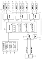
- FIG. 1 is a schematic diagram showing a schematic configuration of a combination weigher according to an embodiment of the present invention.
- FIG. 2 is a block diagram showing a schematic configuration of a control system of the combination weigher.
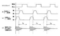
- FIG. 3 is a timing chart showing an example of the operation in the correction operation mode.
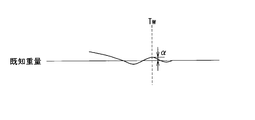
- FIG. 4 is a diagram showing an example of a weight signal waveform near the weighing timing.
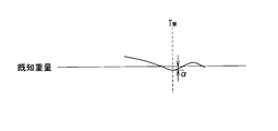
- FIG. 5 is a diagram showing another example of the weight signal waveform near the weighing timing.
- FIG. 6 is a diagram showing another example of the weight signal waveform near the weighing timing.
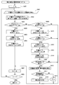
- FIG. 7 is a flowchart showing an outline of processing in the correction operation mode.
- FIG. 8 is a flowchart showing processing for the distributed feeder and the linear feeder.
- FIG. 8 is a flowchart showing processing for the distributed feeder and the linear feeder.
- FIG. 9 is a flowchart showing the processing for the supply hopper.
- FIG. 10 is a flowchart showing a process for the weighing unit in the correction operation mode.
- FIG. 11 is a flowchart showing the combination calculation process.
- FIG. 12 is a flowchart showing the processing for the weighing hopper.
- FIG. 13 is a flowchart showing a process for the weighing unit in the normal operation mode.
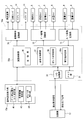
- FIG. 14 is a block diagram corresponding to FIG. 2 of another embodiment of the present invention.
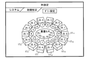
- FIG. 15 is a diagram showing an example of a setting display screen for the dummy correction operation mode.
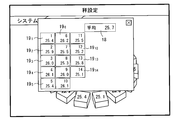
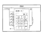
- FIG. 16 is a diagram illustrating an example of a virtual weight setting display screen in the dummy correction operation mode.
- 17 is a diagram showing another example of the virtual weight setting display screen in the dummy correction operation mode.
- FIG. 1 is a schematic diagram showing a schematic configuration of a combination weigher according to an embodiment of the present invention.
- the combination weigher of this embodiment is provided with a dispersion feeder 2 that disperses the objects to be weighed supplied from the supply device 1 radially by vibration at the center of the upper part thereof.
- the dispersion feeder 2 includes a conical top cone 3 to which an object to be weighed is supplied and a vibration mechanism 4 that vibrates the top cone 3.
- the supply device 1 conveys an object to be weighed supplied from a belt conveyor (not shown) by vibration and supplies it to the central portion of the top cone 3.
- the object to be weighed supplied from the supply device 1 to the central portion of the top cone 3 is conveyed toward the peripheral portion of the top cone 3 by vibration.
- Each linear feeder 14 includes a bowl-shaped feeder pan 6 to which an object to be weighed is supplied, and an excitation mechanism 7 that vibrates and drives the feeder pan 6.
- a plurality of supply hoppers 5 and weighing hoppers 8 are provided corresponding to the periphery of each feeder pan 6 and are arranged circumferentially. Discharge gates 5 a and 8 a that can be opened and closed are respectively provided at lower openings of the supply hopper 5 and the weighing hopper 8.
- the supply hopper 5 temporarily holds the object to be weighed sent from the feeder pan 6, and when the weighing hopper 8 disposed below the supply hopper 5 becomes empty, the discharge gate 5 a is opened to load the object to be weighed into the weighing hopper 8.
- Each weighing hopper 8 is connected to and supported by each weight sensor 9 such as a load cell for measuring the weight of an object in the weighing hopper 8.
- Each weight signal from each weight sensor 9 is output to the control device 10.
- the linear feeder 14, the supply hopper 5, the weighing hopper 8, and the weight sensor 9 constitute a set of weighing heads, and the combination weigher includes a plurality of weighing heads, in this example, 14 weighing heads. .
- the control device 10 amplifies the analog weight signal from each weight sensor 9 by the A / D conversion circuit unit of the control device 10, and the A / D converter of the A / D conversion circuit unit performs A at predetermined time intervals. / D conversion, and A / D conversion value is converted to actual weight value.
- the control device 10 corrects each converted weight value by a zero point correction value (tare weight) that is a weight value when each weighing hopper 8 is empty, and is to be weighed supplied to each weighing hopper 8. Calculate each weight measurement of the object.
- the control device 10 performs a combination calculation based on the calculated weight measurement values of the objects to be weighed, and selects an appropriate combination of the weighing hoppers 8 from which the objects to be weighed are to be discharged out of the plurality of weighing hoppers 8.
- a discharge request signal is input from the packaging machine 13
- the discharge gate 8 a of the weighing hopper 8 corresponding to the selected appropriate amount combination is opened, and the objects to be weighed are discharged to the collecting chute 11.
- the discharged objects to be weighed are put into the packaging machine 13 through the assembly funnel 12 below and packaged.
- the operation setting display unit 15 of this embodiment is configured by, for example, a touch panel, and operates a combination weigher and its operation parameters, for example, a stable time that defines a timing for obtaining a weight value from a filtered weight signal, a filter constant, Or it has the function as a setting part operated in order to perform various settings, such as an operation mode.
- the operation setting display unit 15 displays an operation speed, a combined weight value, various set values, and the like on the screen.
- variations in the weight measurement values of the weighing hoppers 8 are caused by predetermined variations. When it is determined to be large, it has a function as a variation notification unit that displays and notifies that effect.
- the control device 10 performs operation control of the supply device 1 and overall operation of the combination weigher, and performs combination calculation.
- the combination weight obtained by variously combining the weight measurement values of the objects to be weighed among the plurality of weighing hoppers 8 is equal to or heavier than the target combination weight, and Then, one combination of the weighing hoppers 8 closest to the target combination weight is selected as an appropriate amount combination.
- FIG. 2 is a block diagram showing a schematic configuration of the control system of the combination weigher of this embodiment, and parts corresponding to those in FIG. 1 are denoted by the same reference numerals.
- the control device 10 includes an arithmetic control unit 30, a memory unit 31, an A / D conversion circuit unit 32 to which an analog weight signal of each weight sensor 9 supporting each weighing hopper 8 is given, each supply hopper 5 and each weighing hopper 5.
- a gate drive circuit unit 33 that drives the discharge gates 5 a and 8 a of the hopper 8, a vibration control circuit unit 34 that controls vibrations of the supply device 1 and the feeders 2 and 14, and an I connected to the packaging machine 13. / O circuit unit 35.
- the calculation control unit 30 includes a CPU, controls each unit, performs calculations such as filter processing and combination calculation, and functions as the control unit 36 and the combination calculation unit 37.
- the combination calculation unit 37 calculates the weight measurement values of the objects to be weighed held in the weighing hoppers 8 from the weight signals of the weight sensors 9 that have been filtered, and performs combination calculation based on the calculated weight measurement values. I do.
- the arithmetic control unit 30 includes a correction value determining unit 38 that determines each correction value for correcting each error of each weight measurement value of each weighing hopper 8, and a weighing hopper, as will be described later. It has a function as a variation determination unit 39 that calculates each variation of the weight measurement value every 8 and determines whether or not the variation is larger than a predetermined variation.
- the memory unit 31 stores an operation program for the combination weigher, operation parameters to be set, and the like, and serves as a work area for operations for the operation control unit 30.
- the A / D conversion circuit unit 32 amplifies the analog weight signal from each weight sensor 9 that detects the weight of the object to be weighed in each weighing hopper 8, samples the analog weight signal with a predetermined period by the A / D converter, and digitally The signal is converted into a signal and output to the arithmetic control unit 30.
- the arithmetic control unit 30 converts each digital signal from the A / D conversion circuit unit 32 into an actual weight value and performs a filter process.
- the arithmetic control unit 30 constitutes, together with the memory unit 31, a digital filter for performing the filter processing, for example, a moving average filter or FIR filter for performing multiple moving average processing.
- the gate drive circuit unit 33 controls the opening and closing of the discharge gates 5 a and 8 a of each supply hopper 5 and each weighing hopper 8 based on a control signal from the arithmetic control unit 30.
- the vibration control circuit unit 34 controls each vibration operation of the supply device 1, the dispersion feeder 2, and each linear feeder 14 based on a control signal from the arithmetic control unit 30.
- the arithmetic control unit 30 is connected to the operation setting display unit 15 so as to communicate with each other.
- the control device 10 controls the operation of the entire combination weigher when the arithmetic control unit 30 executes the operation program stored in the memory unit 31.
- the combination weigher it is necessary to set a large number of operating parameters, and the setting is performed by the operator operating the operation setting display unit 15.
- the set operation parameter value is sent to the arithmetic control unit 30 and stored in the memory unit 31.
- the operating parameters to be set include a stabilization time that defines the timing for obtaining the weight value from the filtered weight signal, a filter constant, a target combination weight that is a target value in the combination calculation, and an allowable range for each, There are 14 vibration strengths, driving times, and the like.
- each weight measurement value of an object to be weighed measured by each weighing hopper 8 due to various effects such as vibration of the combination weigher and floor vibration at a site where the combination weigher is installed, There is an error between the actual weight value of the objects to be weighed in each weighing hopper 8.
- the combination weigher of this embodiment includes, as operation modes, a normal operation mode in which an object to be weighed is supplied to the combination weigher and a normal operation operation is performed, and each weighing hopper is supplied without supplying an object to be weighed to the combination weigher. And a correction operation mode for determining each correction value for correcting each error generated between each weight measurement value measured at 8 and the actual weight value of each weighing hopper 8.
- the correction operation mode is executed, and each error of each weight measurement value measured by each weighing hopper 8 is determined.
- Each correction value for correcting is determined.
- a normal operation mode which is a normal operation mode is executed, and each weight measurement value of the object measured by each weighing hopper 8 is corrected by each correction value, and each weight measurement value corrected is corrected.
- the combination calculation is performed based on the above.
- a test article having a known weight for example, a known weight corresponding to the weight of the object to be weighed, is supplied to each weighing hopper 8 without supplying the object to the combination weigher.
- the operation is performed by attaching the weights so that they are not discharged even when the discharge gate 8a of each weighing hopper 8 is opened.
- the combination weigher operates as if each weighing hopper 8 is loaded with an object to be weighed corresponding to a weight of a known weight.
- the test article is not limited to a weight, and a known-weight object to be weighed may be used. This known-weight object is attached to the weighing hopper 8 so that it is not discharged even when the discharge gate 8a is opened. Also good.
- a weight of a known weight is attached to each weighing hopper 8, and the operation setting display unit 15 having a function as the correction operation mode setting unit 41 is operated to set the correction operation mode.
- the operation setting display unit 15 having a function as the known weight setting unit 42 is operated to set the known weights of the weights attached to the respective weighing hoppers 8.
- the correction operation mode and the known weight are set and the correction operation mode is executed. That is, when the correction operation is started, the weight to be weighed in each weighing hopper 8 is not actually present, but the weight is known. The operation is performed assuming that an object to be weighed is supplied.
- the calculation control unit 30 of the combination weigher selects an appropriate combination at the time of discharge of an object to be weighed at a fixed time interval in the correction operation even if no discharge request signal is input from the packaging machine 13 in the correction operation.
- the discharge gate 8a is opened and closed.
- the arithmetic and control unit 30 opens and closes the gate 8a and discharges the object to be weighed, and in order to supply a new object to be weighed to the weighing hopper 8, the gate 5a for discharging the corresponding supply hopper 5 is opened. Open and close.
- the arithmetic control unit 30 drives the corresponding linear feeder 14 for a set time to supply the objects to be weighed to the supply hopper 5 by opening and closing the gate 5a and discharging the objects to be weighed. Further, the weighing cycle of driving the dispersion feeder 2 over a set time in order to supply the object to be weighed to the linear feeder 14 is repeated.
- Such a weighing cycle is basically the same as a normal operation mode that is a normal operation operation in which an object to be weighed is supplied.
- the stay prevention process is performed so that the object to be weighed is not discharged from the weighing hopper 8 and the stay hopper stays in the weighing hopper 8 for a long time. However, this stay prevention process is also performed during the correction operation.
- FIG. 3 is a timing chart showing an example of the operation in the correction operation.
- 4A shows the driving state of the linear feeder 14
- FIG. 2B shows the open / close state of the discharge gate 5a of the supply hopper 5
- FIG. 3C shows the discharge gate 8a of the weighing hopper 8.
- FIG. 4D shows the weight signal from the weight sensor 9 in the open / closed state.
- FIG. 3 representatively shows a state of a set of weighing heads including the linear feeder 14, the supply hopper 5, the weighing hopper 8, and the weight sensor 9.
- a combination operation is performed based on each weight measurement value of the weight attached to each weighing hopper 8, and the discharge object is discharged to discharge the object to be weighed from the weighing hopper 8 selected as an appropriate amount combination.
- the gate 8a is opened and closed as shown in FIG.
- the discharge gate 5a of the corresponding supply hopper 5 is shown in FIG. It is opened and closed as shown in (b).
- FIG. The metering cycle of being driven for a set time is repeated.
- the timing for obtaining the weight value from the filtered weight signal starting from the opening timing t1 of the discharge gate 5a of the supply hopper 5
- the stabilization time Ts until is set.
- 4 to 6 are waveform diagrams of weight signals in the vicinity of the weighing timing Tw, which is the elapsed time of the stable time Ts in the correction operation.
- the waveform of the weight signal should converge to the known weight of the weight attached to the weighing hopper 8.
- the waveform of the weight signal varies due to the influence of the vibration of the combination weigher and the floor vibration where the combination weigher is installed.
- the weight signal coincides with the known weight, as shown in FIG. 4, exceeds the known weight, or falls below the known weight, as shown in FIG.
- An error ⁇ occurs with respect to the known weight which is the actual actual weight value.
- the correction value determination unit 38 of the calculation control unit 30 stores each weight measurement value calculated from the weight signal of each weighing hopper 8 for a predetermined number of times, and for each weighing hopper 8, the predetermined number of times. Each average value of the weight measurement values is calculated.
- the predetermined number of times is not particularly limited as long as it is a plurality of times, but it is preferably, for example, ten times or more so that a tendency of variation in the weight measurement value of each weighing hopper 8 appears.
- the correction value determination unit 38 calculates the weight measurement value for each weighing hopper 8 from the average value of the weight measurement values calculated for each weighing hopper 8 and the respective known weights of the weights of the weighing hoppers 8 as follows: Each error is calculated.
- Error average value of weight measurement values for a predetermined number of times ⁇ known weight
- the correction value determination unit 38 determines and stores each calculated error for each weighing hopper 8 as each correction value.
- the difference between the weight measurement value for each time and the known weight may be calculated, and the average value of the difference for the predetermined number of times may be used as an error.
- the variation determination unit 39 of the arithmetic control unit 30 calculates each standard deviation, which is a predetermined number of weight measurement value variations for each weighing hopper 8, and each standard deviation of the calculated weight measurement values is determined based on a predetermined standard deviation.
- each standard deviation which is a predetermined number of weight measurement value variations for each weighing hopper 8
- each standard deviation of the calculated weight measurement values is determined based on a predetermined standard deviation.
- the operator assumes that the measured hopper 8 has a large variation in the weight measurement value and is difficult to correct with the correction value. Adjust the stabilization time and filter constant, and execute the correction operation again.
- each correction value for correcting each error of each weight measurement value is determined and stored for each weighing hopper 8.
- each weight measurement value of each weighing hopper 8 is corrected with each correction value determined in the correction operation mode. That is, as shown in the following equation, each correction value is subtracted from each weight measurement value and corrected.
- Corrected weight measurement value weight measurement value ⁇ correction value In the normal operation mode, combination calculation is performed based on each corrected weight measurement value.
- the correction operation is performed in advance to obtain each correction value for correcting each error of each weight measurement value for each weighing hopper 8, and each weight measurement value of each weighing hopper 8 during normal operation. Is corrected with each correction value, and the combination calculation is performed with each corrected weight measurement value. Therefore, the combination calculation is performed with each accurate weight measurement value, and the measurement accuracy is improved.
- FIG. 7 is a flowchart showing an outline of the entire process in the correction operation mode.
- the dispersion unit control in step S101, the supply hopper control in step S102, the correction operation weighing unit control in step S103, the combination calculation in step S105, and the weighing hopper control in step S107 in FIG. Based on the above, further details will be described.
- the discharge gates 5a and 8a of the hoppers 5 and 8 are not opened and closed, and the objects to be weighed are not discharged. Even if each of the feeders 2 and 14 is driven, the object to be weighed is not transported and supplied downstream.
- the operation setting display unit 15 is operated by the operator to set the correction operation mode and the known weight, and then the operation switch for starting the correction operation is turned on. Then, the correction operation is started (step S100).
- the arithmetic control unit 30 of the control device 10 controls the dispersion unit including the dispersion feeder 2 and the linear feeder 14 (step S101). In the control of the dispersing unit, the feeder pan 6 of the linear feeder 14 corresponding to the supply hopper 5 that opens and closes the discharge gate 5a is vibrated. Further, the top cone 3 of the dispersion feeder 2 is vibrated.
- the arithmetic control unit 30 controls the discharge gate 5a of the supply hopper 5, and opens and closes the discharge gate 5a of the supply hopper 5 corresponding to the weighing hopper 8 that opens and closes the discharge gate 8a (step) S102).
- the arithmetic and control unit 30 controls the weighing unit and assumes that the object to be weighed is supplied to the weighing hopper 8 by opening and closing the discharge gate 5a of the supply hopper 5, and the weighing sensor 9 performs the above weighing.
- the weight of the object to be weighed supplied to the hopper 8 is measured. That is, the weight value is acquired from the weight signal of the weight sensor 9, and the weight measurement value is calculated (step S103).
- the arithmetic control unit 30 determines whether or not it is a discharge timing for discharging an object to be weighed by the weighing hopper 8 in an appropriate amount combination (step S104).
- the measured value of the discharge timing timer is decremented by 1, and the process proceeds to step S107 (step S109).
- step S104 when it is the discharge timing, the calculation control unit 30 performs a combination calculation based on each weight measurement value corresponding to the weight attached to each weighing hopper 8 (step S105).
- the combined weight which is the total weight obtained by combining various weights of the respective weight measurement values, is equal to or larger than the target combination weight and the weight closest to the target combination weight is measured.
- the appropriate amount combination which is the combination of the hopper 8 is selected, and it moves to step S106.
- step S106 in order to measure the next discharge timing, the calculation control unit 30 sets a discharge timing timer to start measurement, and proceeds to step S107.
- step S107 the calculation control unit 30 performs weighing hopper control, opens and closes the discharge gate 8a of the weighing hopper 8 of the appropriate amount combination selected in the combination calculation, and proceeds to step S108.
- step S108 it is determined whether or not the operation switch is turned off. If it is not turned off, the process returns to step S101, and if it is turned off, the correction operation is terminated.
- FIG. 8 is a flowchart showing the processing of the distribution unit control program in step S101 of FIG.
- the arithmetic control unit 30 sets a number k for specifying the first linear feeder 14 of the plurality of linear feeders 14 to an initial value “1” (step S200), and for this linear feeder 14 (k), It is determined whether or not a driving flag indicating that the driving is in progress is “ON” (step S201).
- the driving flag is “ON”
- the arithmetic control unit 30 measures the linear feeder 14 (k) for measuring the driving time of the linear feeder 14 (k).
- the measured value of the built-in drive time measuring timer corresponding to (1) is subtracted by one and the process proceeds to step S203 (step S202).
- the processing of FIG. 8 is executed at regular intervals, and the drive time of the linear feeder 14 (k) is measured by subtracting one measurement value of the drive time measurement timer.
- step S203 whether or not the measured value of the driving time measuring timer of the linear feeder 14 (k) has reached “0”, that is, the driving time measuring timer has timed up and the driving time of the linear feeder 14 (k) is reached. It is determined whether or not the process has ended.
- step S203 when the measured value of the drive time measurement timer of the linear feeder 14 (k) becomes “0”, the arithmetic control unit 30 stops driving the linear feeder 14 (k) (step S204), and linear The driving flag for the feeder 14 (k) is turned “OFF” and the process proceeds to step S206 (step S205).
- step S203 when the measured value of the driving time measurement timer of the linear feeder 14 (k) is not “0”, the process proceeds to step S206.
- step S206 “1” is added to the number k specifying the linear feeder 14, and it is determined whether or not the number k has reached “n + 1”, that is, whether or not all the linear feeders 14 have been processed (step S206).
- step S207 If “n + 1” is not reached, the process returns to step S201 and the next linear feeder 14 is processed in the same manner.
- step S207 when the number k becomes “n + 1”, it is determined whether any of the linear feeders 14 is being driven (step S208).
- the dispersion feeder 2 is turned “ON” to start driving the dispersion feeder 2, or the driving of the dispersion feeder 2 is continued and ended (step S209).
- step S208 when none of the linear feeders 14 is being driven, the dispersion feeder 2 is turned “OFF”, and the driving of the dispersion feeder 2 is stopped (step S210).
- step S201 when the driving flag for the linear feeder 14 (k) is not “ON”, the arithmetic control unit 30 sets the linear feeder 14 (k) for starting the driving of the linear feeder 14 (k). It is determined whether or not the drive command flag is “ON” (step S211). When the drive command flag for the linear feeder 14 (k) is not “ON”, the arithmetic control unit 30 proceeds to step S206, and when the drive command flag for the linear feeder 14 (k) is “ON”, step S212. Move on. In step S212, the arithmetic control unit 30 turns on the driving flag of the linear feeder 14 (k) indicating that the linear feeder 14 (k) is being driven, and sets the driving time of the linear feeder 14 (k).
- a drive time measurement timer for measurement is set and measurement of the drive time is started (step S213), and the linear feeder 14 (k) is turned “ON” to start driving the linear feeder 14 (k) (step S214). Further, the drive command flag of the linear feeder 14 (k) is turned “OFF”, and the process proceeds to step S206 (step S215).
- FIG. 9 is a flowchart showing the processing of the supply hopper control program in step S102 in FIG.
- the arithmetic control unit 30 sets the number k for specifying the first supply hopper 5 of the plurality of supply hoppers 5 to an initial value “1” (step S300), and discharges the supply hopper 5 (k). It is determined whether or not the discharge gate opening / closing flag indicating that the opening / closing operation of the gate 5a should be performed is “ON” (step S301), and when it is “ON”, the supply hopper 5 (k) is discharged.
- the opening / closing operation of the supply gate 5a is controlled (step S302), and it is determined whether the opening / closing operation of the discharge gate 5a of the supply hopper 5 (k) is completed (step S303). Then, the discharge gate open / close flag for the supply hopper 5 (k) is turned “OFF” (step S304), and the process proceeds to step S305.
- step S305 the calculation control unit is set so that a new object to be weighed is supplied.
- step S307 the drive command flag of the linear feeder 14 (k) corresponding to the supply hopper 5 (k), and set the stable start flag for starting the measurement of the stable time for the weighing hopper 8 (k) to " "ON” and the process proceeds to step S307 (step S306).
- step S303 when the opening / closing operation of the discharge gate 5a of the supply hopper 5 (k) is not completed, the process proceeds to step S307.
- step S301 when the discharge gate opening / closing flag of the supply hopper 5 (k) is not “ON”, the arithmetic control unit 30 has the discharge gate opening / closing command flag for the supply hopper 5 (k) “ON”. Whether or not (step S309).
- the discharge gate open / close command flag for the supply hopper 5 (k) is “ON”
- the discharge gate open / close flag indicating that the discharge gate 5a of the supply hopper 5 (k) should be opened / closed is “ON”.
- the discharge gate opening / closing command flag for the supply hopper 5 (k) is turned “OFF”, and the process proceeds to step S307 (step S311).
- step S307 “1” is added to the number k that identifies the supply hopper 5, and it is determined whether or not the number k has reached “n + 1”, that is, whether or not all the supply hoppers 5 have been processed (step S307). S308), if not "n + 1", the process returns to step S301 and the same processing is performed for the next supply hopper 5. In step S308, when the number k becomes “n + 1”, the process ends.
- FIG. 10 is a flowchart showing the process of the weighing unit control program in step S103 of FIG. 7, and includes a process for calculating an error and determining a correction value.
- the arithmetic control unit 30 sets the number k for specifying the first weighing hopper 8 of the plurality of weighing hoppers 8 to an initial value “1” (step S400), and corresponds to the weighing hopper 8 (k).
- the weight value is calculated from the weight signal of the weight sensor 9 (step S401), and the weight data calculated from the weight sensor 9 of the weighing hopper 8 (k) is filtered (step S402).
- the arithmetic control unit 30 determines whether or not the stable start flag indicating the start of the measurement of the stable time is “ON” for the weighing hopper 8 (k) (step S403).
- the arithmetic control unit 30 sets the built-in stable time measurement timer corresponding to the weighing hopper 8 (k) and measures the stable time in order to measure the stable time.
- Start step S404
- the stable flag indicating that the measurement time of the weighing hopper 8 (k) is being measured is “ON” (step S405)
- the stable start flag of the weighing hopper 8 (k) is set to “OFF”. Then, the process proceeds to step S407 (step S406).
- step S403 when the stable start flag of the weighing hopper 8 (k) is not “ON”, the stable flag of the weighing hopper 8 (k) indicating that the stable time is being measured is “ON”.
- Step S409 when the stable flag is “ON”, the arithmetic control unit 30 subtracts one measurement value of the stable time measurement timer corresponding to the weighing hopper 8 (k).
- Step S410 the process proceeds to Step S411.
- the processing of FIG. 10 is executed at regular intervals, and the stable time of the weighing hopper 8 (k) is measured by subtracting one measurement value of the stable time measurement timer.
- step S411 the arithmetic control unit 30 determines whether or not the measurement value of the stable time measurement timer of the weighing hopper 8 (k) has reached “0”, that is, the stable time measurement timer has timed out and the stable time has elapsed. Determine whether or not.
- step S411 when the measured value of the stable time measurement timer of the weighing hopper 8 (k) becomes “0”, since the stable time has elapsed, the arithmetic control unit 30 is stabilizing the weighing hopper 8 (k).
- the flag is set to “OFF” (step S412), and the combination calculation unit 37 obtains a weight value from the filtered weight data, calculates a weight measurement value of the weighing hopper 8 (k), and measures the weighing hopper 8 (k).
- the measurement completion flag is turned “ON” (step S413).
- step S414 the calculation control unit 30 totals the calculated weight measurement values (step S414), and determines whether or not the total number of the calculated weight measurement values of the objects to be weighed has reached a predetermined number (step S415). When the predetermined number of times has not been reached, the process proceeds to step S407. When the predetermined number has been reached, the process proceeds to step S416.
- step S416 the arithmetic control unit 30 calculates the average value of the weight measurement values for the predetermined number of times of the total weighing hopper 8 (k), and the known weight of the weight corresponding to the average value and the weighing hopper 8 (k). And the error is calculated. In addition, the arithmetic control unit 30 calculates a standard deviation that is a variation in the weight measurement value of the object to be weighed by the weighing hopper 8 (k) for a predetermined number of times, and the calculated standard deviation is less than a predetermined value. It is determined whether or not (step S417).
- step S408 determines the calculated error as a correction value and proceeds to step S407 (step S418), and when the calculated standard deviation is not less than the predetermined value, Since the variation is large, the notification is displayed on the operation setting display unit 15 and the process proceeds to step S407 (step S419).
- step S407 the arithmetic control unit 30 adds “1” to the number k that identifies the weighing hopper 8, and whether or not the number k has become “n + 1”, that is, whether all the weighing hoppers 8 have been processed. (Step S408), and if it is not "n + 1", the process returns to step S401 and the same processing is performed for the next weighing hopper 8. In step S408, when the number k becomes “n + 1”, the process ends.
- FIG. 11 is a flowchart showing the processing of the combination calculation program in step S105 in FIG.
- step S500 priority is given to the weighing hopper 8 that has not been selected as an appropriate combination continuously for a certain number of times or more, and an appropriate combination that is closest to the target combination weight is searched (step S500).
- the combination discharge flag indicating that the object to be weighed should be discharged is set to “ON”, and the process ends (step S501).
- FIG. 12 is a flowchart showing the processing of the weighing hopper control program in step S107 of FIG.
- the arithmetic control unit 30 sets the number k for identifying the first weighing hopper 8 of the plurality of weighing hoppers 8 to an initial value “1” (step S600), and discharges the weighing hopper 8 (k). It is determined whether or not the discharge gate opening / closing flag indicating that the opening / closing operation of the gate 8a should be performed is “ON” (step S601). In step S701, when the discharge gate opening / closing flag of the weighing hopper 8 (k) is “ON”, the arithmetic control unit 30 controls the opening / closing operation of the discharging gate 8a of the weighing hopper 8 (k) (step S701).
- step S602 it is determined whether or not the opening / closing operation of the discharge gate 8a of the weighing hopper 8 (k) is completed (step S603), and the opening / closing operation of the discharge gate 8a of the weighing hopper 8 (k) is completed. Sometimes, the process proceeds to step S604, and when the opening / closing operation of the discharge gate 8a is not completed, the process proceeds to step S606.
- step S604 the calculation control unit 30 sets the discharge gate open / close flag of the weighing hopper 8 (k) to “OFF”, opens / closes the discharge gate 8a of the weighing hopper 8 (k), and discharges the object to be weighed.
- the discharge gate opening / closing command flag of the supply hopper 5 (k) corresponding to the weighing hopper 8 (k) is set to “ON” so that a correct object to be weighed is supplied, and the process proceeds to step S606 (step S605).
- step S601 when the discharge gate open / close flag of the weighing hopper 8 (k) is not “ON”, the arithmetic control unit 30 determines whether the combined discharge flag of the weighing hopper 8 (k) is “ON”. Is determined (step S608). When the combined discharge flag is “ON”, the discharge gate open / close flag of the weighing hopper 8 (k) is turned ON (step S609), and the combined discharge flag of the weighing hopper 8 (k) is turned “OFF” (step S610). Then, the weighing completion flag of the weighing hopper 8 (k) is set to “OFF”, and the process proceeds to step S606 (step S611).
- step S608 If the combination discharge flag is not “ON” in step S608, the process proceeds to step S606.
- step S606 "1" is added to the number k for specifying the weighing hopper 8, and it is determined whether or not the number k has become "n + 1", that is, whether all the weighing hoppers 8 have been processed (step S606). S607) If not “n + 1”, the process returns to step S601 and the next weighing hopper 8 is similarly processed. In step S607, when the number k becomes “n + 1”, the process ends.
- step S103 of FIG. 7 the operation of the correction operation weighing unit control in step S103 of FIG. 7 is different, and the discharge timing is the timing of the discharge request signal from the packaging machine 13. Since other operations are basically the same as those in the correction operation mode, the control of the weighing unit in the normal operation will be described.
- FIG. 13 is a flowchart showing the processing of the weighing unit control program in step S103 of FIG. 7, and is a flowchart during normal operation.
- the arithmetic control unit 30 sets the number k for specifying the first weighing hopper 8 of the plurality of weighing hoppers 8 to an initial value “1” (step S700), and corresponds to the weighing hopper 8 (k).
- the weight value is calculated from the weight signal of the weight sensor 9 (step S701), and the weight data calculated from the weight sensor 9 of the weighing hopper 8 (k) is filtered (step S702).
- the arithmetic control unit 30 determines whether or not the stable start flag indicating the start of the measurement of the stable time is “ON” for the weighing hopper 8 (k) (step S703).
- step S704 the stable flag indicating that the measurement time of the weighing hopper 8 (k) is being measured is “ON” (step S705), and the stable start flag of the weighing hopper 8 (k) is set to “OFF”. Then, the process proceeds to step S707 (step S706).
- step S703 when the stable start flag of the weighing hopper 8 (k) is not “ON”, the stable flag of the weighing hopper 8 (k) indicating that the stable time is being measured is “ON”.
- Step S709 when the stable flag is “ON”, the arithmetic control unit 30 subtracts one measurement value of the stable time measurement timer corresponding to the weighing hopper 8 (k).
- Step S710 the process proceeds to Step S711.
- the process of FIG. 13 is executed at regular time intervals, and the stable time of the weighing hopper 8 (k) is measured by subtracting one measurement value from the stable time measurement timer.
- step S711 it is determined whether or not the measurement value of the stable time measurement timer of the weighing hopper 8 (k) has reached “0”, that is, whether or not the stable time measurement timer has expired and the stable time has elapsed. .
- step S711 when the measurement value of the stable time measurement timer of the weighing hopper 8 (k) becomes “0”, the correction value obtained in the correction operation mode is added to the weight measurement value of the weighing hopper 8 (k). Then, the weight measurement value of the weighing hopper 8 (k) is corrected, and the process proceeds to Step S713 (Step S712).
- step S713 the stable flag for the weighing hopper 8 (k) is turned “OFF” (step S713), the weighing completion flag for the weighing hopper 8 (k) is turned “ON” (step S714), and the process proceeds to step S707.
- step S711 when the measured value of the stable time measurement timer of the weighing hopper 8 (k) is not “0”, the process proceeds to step S707.
- step S707 "1" is added to the number k specifying the weighing hopper 8, and it is determined whether or not the number k has become "n + 1", that is, whether all the weighing hoppers 8 have been processed (step S707). S708) If not "n + 1", the process returns to step S701 and the same processing is performed for the next weighing hopper 8. In step S708, when the number k becomes “n + 1”, the process ends.
- each weight measurement value of each weighing hopper 8 is corrected for each error by each correction value obtained in the correction operation mode. Based on the value, the combination calculation is performed as shown in FIG. 11, so that the measurement accuracy is improved.
- the correction operation is performed in a state where a weight or the like, which is a test article of a known weight, is attached to each weighing hopper 8 so that it is not discharged even when the discharge gate 8a is opened.
- a correction operation may be performed without attaching a test article such as a weight to each weighing hopper 8.
- the combination weigher can be corrected and operated by a simple operation without attaching a test article such as a weight to the weighing hopper 8 as follows.
- a correction operation mode in which a correction operation is performed in a simulated manner without supplying an object to be weighed to the combination weigher and without attaching a test article to the weighing hopper 8.
- the correction operation mode in which the correction operation is simulated is referred to as a dummy correction operation mode.
- FIG. 14 is a block diagram corresponding to FIG. 2 of this embodiment, and parts corresponding to those in FIG.
- the operation setting display unit 15a includes a dummy operation mode setting unit 40 that sets a dummy correction operation mode as an operation mode, and each known virtual object of a virtual article that is virtually held in each weighing hopper 8 in the dummy correction operation mode. It has a function as a virtual weight setting unit 43 for setting the weight.
- the correction value determination unit 38a of the arithmetic control unit 30a is based on each weight measurement value calculated as described later from the weight signal of each weighing hopper 8 and each known virtual weight of the virtual article of each weighing hopper 8. As in the correction operation mode of the first embodiment, each correction value for correcting each error of the weight measurement value for each weighing hopper 8 is determined.
- FIG. 15 is a diagram illustrating an example of a setting display screen displayed on the operation setting display unit 15 in the setting of the dummy correction operation mode.
- the dummy correction operation mode is a mode in which the combination weigher is simulated and corrected without actually supplying an object to be weighed to the combination weigher and without attaching a test article such as a weight to the weighing hopper 8. is there.
- a virtual article is virtually held in each weighing hopper 8 even when each weighing hopper 8 is empty. Need to work. For this reason, the weight of each virtual article virtually held by each weighing hopper 8 is set as each virtual weight.
- FIG. 15 is an example of a setting display screen of the operation setting display unit 15 when setting the virtual weight.
- the numbers “1” to “14” indicating the respective weight sensors 9 corresponding to the 14 weighing hoppers 8 of the combination weigher are indicated by 14 circular numbers arranged circumferentially. It is displayed in the areas 16 1 to 16 14 . Further, on the outer peripheral side of the number display area 16 1 to 16 14, block-shaped virtual weight display area 17 1 to 17 14 to correspond to each number display area 16 1-16 14 appears, these virtual weight The set virtual weights are displayed in the display areas 17 1 to 17 14 , respectively.
- “25.4” g is set as the virtual weight for the first weighing hopper 8 with the number “1”, and the virtual weight is set for the second weighing hopper 8 with the number “2”.
- “25.9” g is set, “26.0” g is set as the virtual weight in the third weighing hopper 8 with the number “3”, and similarly, the fourteenth weighing with the number “14”.
- “25.1” g is set as a virtual weight.
- the first weighing hopper 8 with the number “1” virtually holds the virtual article “25.4” g
- the virtual article “25.9” g is virtually held
- the virtual weighing article “26.0” g is virtually stored in the third weighing hopper 8 with the number “3”. Will be retained.
- the virtual weighing item “25.1” g is virtually held in the fourteenth weighing hopper 8 with the number “14”.
- each virtual weight In the setting of each virtual weight in this example, the operator sets the average value of the weight values of the objects to be supplied to the first to fourteenth weighing hoppers 8 by operating the operation setting display unit 15. . As a result, the arithmetic control unit 30 automatically calculates and sets each virtual weight of each of the first to fourteenth weighing hoppers 8 by varying the average value.
- FIG. 16 is an example of a setting display screen showing automatic setting of each virtual weight by setting the average value of the virtual weight.
- “25.7” g is set by the operator as an average value of the weight values of the objects to be weighed to be supplied to the first to fourteenth weighing hoppers 8, and the value is It is displayed in the rectangular average value display area 18.
- the arithmetic control unit 30 automatically calculates the virtual weights corresponding to the first to fourteenth weighing hoppers 8 by varying the set average value.
- the calculated virtual weights are displayed in the 14 rectangular display areas 19 1 to 19 14 together with the numbers “1” to “14” of the respective weighing hoppers 8. That is, in this embodiment, the virtual weights are not set directly, but the virtual weights can be set indirectly by setting the average value of the weights of the objects to be weighed to be supplied to the weighing hoppers 8. it can.
- the average value of the weight values of the objects to be weighed to be supplied to each weighing hopper 8, that is, the target weight value of the objects to be weighed to be supplied to each weighing hopper 8, increases the number of effective combinations. In order to increase the combination accuracy, it is preferable to calculate as follows.
- the weight value obtained by dividing the target combination weight by (n-1) / 2 or (n + 1) / 2 is obtained.
- the target weight value of the object to be weighed should be supplied to
- the weight value obtained by dividing the target combination weight by n / 2 may be set as the target weight value of the object to be weighed to be supplied to the weighing hopper 8.
- the arithmetic control unit 30 sets the target combination weight to the above (n ⁇ 1) / 2, (n + 1) / 2, or n / 2 depending on whether the total number n is an odd number or an even number.
- the average value of the weight values of the objects to be weighed to be supplied to each weighing hopper 8 is calculated, and the average value is automatically dispersed to calculate each virtual weight and set it automatically. It may be. That is, even if the virtual weight is not set directly, the virtual weight is automatically calculated, for example, indirectly by the operator setting the dummy correction operation mode and setting the target combination weight value. It may be set.
- the operator operates the operation setting display unit 15a to call the numeric keypad window 20 and directly set the virtual weight of each weighing hopper 8 individually as shown in the setting display screen example of FIG. It can also be set.
- each weight measurement value of each weighing hopper 8 is calculated on the assumption that the virtual article having each set virtual weight is held in each weighing hopper 8. To do.
- the method of calculating each weight measurement value of each weighing hopper 8 is different from the normal operation mode and the correction operation mode of the first embodiment.
- initial zero-point correction values used when calculating each weight measurement value of the weighing object supplied to each weighing hopper 8 are set.
- Each weight is corrected with each virtual weight, and each weight measurement value of the object to be weighed is calculated using each corrected zero correction value.
- the tare weight (weighing hopper) is calculated from the weight measurement value calculated from the weight signal of the weight sensor 9 in an empty state in which the weighing object is not supplied to the weighing hopper 8.
- the tare weight is determined so that the weight measurement value obtained by subtracting the weight of the 8 itself and the weight of the support member or the like supporting the weighing hopper 8 becomes zero, and this tare weight is corrected to the initial zero point. Value (zero calibration value).
- the initial zero point correction value which is the tare weight
- the weight measurement value calculated from the weight signal of the weight sensor 9 and supplied to the weighing hopper 8.
- the initial zero point correction value which is the tare weight is obtained from the weight measurement value acquired from the weight signal of the weight sensor 9 corresponding to the weighing hopper 8. Since subtraction is performed, “0” g is calculated as the weight measurement value of the object to be weighed in the weighing hopper 8.
- the weight measurement value of each weighing hopper 8 is calculated by performing the normal zero point adjustment.
- the corrected zero value is calculated by correcting the initial zero value by the set virtual weight.
- This corrected zero correction value is the initial zero correction value so that the virtual weight is calculated as the weight value of the weighing object in the weighing hopper 8 in an empty state where the weighing object is not supplied to the weighing hopper 8. Is a corrected value.
- the weight measurement value calculated from the weight signal of the weight sensor 9 corresponding to the weighing hopper 8 is 1520 g, for example, in an empty state where the object to be weighed is not supplied to the weighing hopper 8.
- 1520 g is the tare weight obtained by adding the weight of the weighing hopper 8 itself and the weight of the supporting member that supports the weighing hopper 8, and the 1520 g is stored as the initial zero correction value (Wzi). .
- the initial zero point correction value (Wzi) is subtracted from the weight measurement value (Wm) acquired from the weight signal of the weight sensor 9 to obtain the weight measurement value Wn of the object to be weighed.
- Wn (Wm ⁇ Wzi) For example, if the weight measurement value (Wm) acquired from the weight signal of the weight sensor 9 is 1545 g, the initial zero correction value (Wzi) 1520 g is subtracted from this 1545 g to determine the weight measurement value of the object to be weighed. (Wn) 25 g is calculated as follows.
- the virtual weight (Ws) is used as the weight measurement value (Wn) of the object to be weighed in an empty state where the object to be weighed is not supplied to the weighing hopper 8.
- the initial zero correction value (Wzi) is corrected so as to be calculated.
- the initial zero correction value (Wzi) is 1520 g as described above and the set virtual weight (Ws) is 25.5 g
- the following formula is established for the corrected zero correction value (Wzir): To be calculated.
- the weight measurement value (Wn) of the object to be weighed by the weighing hopper 8 is calculated as follows by subtracting the corrected zero correction value Wzir from the weight value (Wm) acquired from the weight signal of the weight sensor 9. .
- Wn Wm-Wzir
- the weight measurement value (Wm) calculated from the weight signal of the weight sensor 9 corresponding to the weighing hopper 8 in the empty state in which the object to be weighed is not supplied to the weighing hopper 8 is the initial zero correction value as described above. That is, it is assumed that the tare weight is 1520 g.
- the weight measurement value (Wn) of the object to be weighed is calculated by subtracting 1494.5 g which is the corrected zero point correction value (Wzir) from this weight measurement value (Wm), the virtual weight (Ws) is obtained as follows. 25.5 g is calculated.
- the virtual weight is calculated as the weight of the weighing object in the weighing hopper 8 even in an empty state where the weighing object is not supplied to the weighing hopper 8.
- the initial zero-point correction value is corrected according to the virtual weight, that is, the zero point, which is a reference for calculating the weight measurement value, is shifted so as to correspond to the virtual weight. Even in an empty state where no is supplied, a virtual weight is calculated as a weight measurement value of the object to be weighed.
- each weight of an object to be weighed by each weighing hopper 8 due to various effects such as vibration of the combination weigher and floor vibration at the site where the combination weigher is installed. There is an error between the measured value and the actual weight value of the weighing object of each weighing hopper 8, that is, the virtual weight.
- This dummy correction operation also operates basically in the same manner as the correction operation mode of the first embodiment, except for calculating the weight measurement value using the corrected zero point correction value.
- the calculation control unit 30a corrects each weight value acquired from the weight signal of each weight sensor 9 corresponding to each weighing hopper 8 with the corrected zero correction value, and measures each weight. A value is calculated, a combination calculation is performed using the calculated weight measurement values of the objects to be weighed, and an appropriate amount combination is selected.
- the arithmetic control unit 30a calculates, for each weighing hopper 8, each average value of the calculated weight measurement value for a predetermined number of times, and calculates an error from the calculated average value and the virtual weight according to the following equation. .
- Error average value of weight measurement values for a predetermined number of times ⁇ virtual weight
- the calculation control unit 30a stores the calculated errors as correction values.
- the calculation control unit 30a opens and closes the discharge gate 8a in order to discharge the objects to be weighed from the weighing hopper 8 selected as an appropriate amount combination when the objects to be weighed are discharged at regular time intervals.
- the arithmetic control unit 30a opens and closes the discharge gate 5a of the corresponding supply hopper 5 in order to supply the object to be weighed to the weighing hopper 8 that has opened and closed the gate 8a.
- the arithmetic control unit 30a drives the corresponding linear feeder 14 for a set time in order to supply the object to be supplied to the supply hopper 5 whose gate 5a is opened and closed, and further, the linear feeder 14 has the object to be weighed.
- the metering cycle is repeated, in which the dispersion feeder 2 is driven for a set time to supply.
- the stay prevention process is performed as in the correction operation mode of the first embodiment. That is, when a weighing hopper 8 that is not selected as an appropriate amount combination is detected continuously for a certain number of times, a staying prevention process is performed in which a combination operation forcibly including the weighing hopper 8 in the appropriate amount combination is performed. As a result, all the weighing hoppers 8 are selected as appropriate combinations.
- the combination weigher Even if the weighing object is attached to the weighing hopper 8 during the normal operation for actually supplying the weighing object, the zero point fluctuates and the weighing object having the same weight is supplied. The measured weight value will change. For this reason, the combination weigher has a function of automatically performing zero point adjustment for periodically updating the zero point correction value during normal operation, but in the dummy correction operation mode for calculating the virtual weight, such automatic zero point adjustment is performed. The function is disabled. Therefore, in the dummy correction operation mode, not the updated zero point correction value but the initial zero point correction value before the normal operation operation is left as the corrected zero point correction value corrected by the virtual weight, and is not updated.
- the variation determination unit 39 of the calculation control unit 30a calculates each standard deviation that is a variation in the weight measurement value for each weighing hopper 8 a predetermined number of times.
- each standard deviation of the measured weight value is larger than a predetermined standard deviation, the fact that the measurement hopper 8 is specified and the variation is large is displayed on the operation setting display unit 15 having a function as the variation notification unit 44. To inform you.
- each correction value for correcting the error of each weight measurement value of each weighing hopper 8 is determined.
- the normal operation mode which is a normal operation for supplying the objects to be weighed
- the respective correction values determined in the dummy correction operation mode as in the normal operation mode of the first embodiment, each of the weighing hoppers 8.
- the weight measurement value is corrected, and a combination calculation is performed based on each corrected weight measurement value.
- a test article such as a weight corresponding to the weight of the object to be weighed is attached so that it is not discharged even when the discharge gate 8a of the weighing hopper 8 is opened, and the correction operation is performed. went. For this reason, each weight etc. corresponding to each weighing hopper 8 is prepared, each weight etc. is attached to each weighing hopper 8 so as not to be discharged from the weighing hopper 8, and the correction operation is performed. Must be removed from the weighing hopper 8 and managed, which is troublesome.
- the test article is attached to the weighing hopper 8 without supplying an object to be weighed to the combination weigher by a simple setting operation such as setting of the dummy correction operation mode. Therefore, a simulated correction operation can be performed.
- the dummy correction operation mode can be easily executed without attaching a weight or the like to the weighing hopper 8, so that the dummy correction operation mode is not limited to the time when the combination weigher is installed and installed, but before the start of normal operation or when the type of the weighing object is switched. Or the like.
- the first embodiment and the second embodiment may be combined. That is, as the correction operation mode, a correction operation mode in which a test article such as a weight is attached to the weighing hopper 8 and a virtual correction operation mode in which no weight or the like is used may be selected.
Landscapes
- Physics & Mathematics (AREA)
- General Physics & Mathematics (AREA)
- Engineering & Computer Science (AREA)
- Quality & Reliability (AREA)
- Mechanical Engineering (AREA)
- Weight Measurement For Supplying Or Discharging Of Specified Amounts Of Material (AREA)
Abstract
Description
当該組合せ秤の運転モードとして、通常運転モードと、前記各重量センサの各重量信号から算出される各重量測定値の各誤差を補正するための各補正値をそれぞれ決定する補正運転モードとを備え、
前記通常運転モードでは、前記組合せ演算部は、前記各重量センサの各重量信号から算出される各計量ホッパに保持されている被計量物の前記各重量測定値を、前記各補正値を用いてそれぞれ補正すると共に、補正した各重量測定値に基づいて、前記組合せ演算を行うものである。
以下、本発明の実施の形態を、図面を参照しながら詳細に説明する。
補正値決定部38は、算出した計量ホッパ8毎の各誤差を、各補正値として決定し、記憶する。
通常運転モードでは、この補正した各重量測定値に基づいて、組合せ演算を行う。
上記第1の実施形態の補正運転モードでは、各計量ホッパ8に、既知重量の試験用物品である分銅等を、排出用のゲート8aが開いても排出されないように取付けた状態で補正運転を行ったけれども、本発明の他の実施形態として、分銅等の試験用物品を、各計量ホッパ8に取付けることなく、補正運転を行えるようにしてもよい。
例えば、重量センサ9の重量信号から取得される重量測定値(Wm)が、1545gであれば、この1545gから初期の零点補正値(Wzi)である1520gを減算して被計量物の重量測定値(Wn)25gが下記のように算出される。
これに対して、この実施形態のダミー補正運転モードでは、計量ホッパ8に被計量物が供給されていない空の状態で、被計量物の重量測定値(Wn)として、仮想重量(Ws)が算出されるように、初期の零点補正値(Wzi)を修正する。
したがって、修正零点補正値(Wzir)は、
Wzir=1520-25.5=1494.5
すなわち、修正零点補正値(Wzir)として、初期の零点補正値(Wzi)1520gを修正した1494.5gが算出される。
計量ホッパ8に被計量物が供給されていない空の状態で、計量ホッパ8に対応する重量センサ9の重量信号から算出される重量測定値(Wm)が、上記のように初期の零点補正値、すなわち、風袋重量である1520gであるとする。この重量測定値(Wm)から修正零点補正値(Wzir)である1494.5gを減算して、被計量物の重量測定値(Wn)を算出すると、下記のように仮想重量(Ws)である25.5gが算出される。
このようにして、ダミー補正運転では、計量ホッパ8に被計量物が供給されていない空の状態であっても、計量ホッパ8の被計量物の重量として、仮想重量が算出される。
演算制御部30aは、算出した各誤差を、各補正値として記憶する。
2 分散フィーダ
5 供給ホッパ
8 計量ホッパ
9 重量センサ
10 制御装置
13 包装機
14 リニアフィーダ
15,15a 操作設定表示部
30,30a 演算制御部
36 制御部
37 組合せ演算部
38,38a 補正値決定部
39 ばらつき判定部
40 ダミー補正運転モード設定部
41 補正運転モード設定部
42 既知重量設定部
43 仮想重量設定部
44 ばらつき報知部
Claims (8)
- 供給される被計量物を周囲へ搬送する分散フィーダと、該分散フィーダの周囲に配設されて前記分散フィーダからの被計量物をそれぞれ搬送して搬送終端から排出する複数のリニアフィーダと、各リニアフィーダの前記搬送終端から排出される被計量物を保持し、保持した被計量物を下方へ供給する複数の供給ホッパと、各供給ホッパから供給される被計量物を保持し、保持した被計量物を排出する複数の計量ホッパと、各計量ホッパの重量をそれぞれ検出する複数の重量センサと、各重量センサの各重量信号から各計量ホッパに保持されている被計量物の重量測定値をそれぞれ算出すると共に、算出した各重量測定値に基づいて、組合せ演算を行う組合せ演算部と、前記組合せ演算の結果に基づいて、前記計量ホッパを制御すると共に、前記分散フィーダ、前記リニアフィーダ及び前記供給ホッパを制御する制御部とを備える組合せ秤であって、
当該組合せ秤の運転モードとして、通常運転モードと、前記各重量センサの各重量信号から算出される各重量測定値の各誤差を補正するための各補正値をそれぞれ決定する補正運転モードとを備え、
前記通常運転モードでは、前記組合せ演算部は、前記各重量センサの各重量信号から算出される各計量ホッパに保持されている被計量物の前記各重量測定値を、前記各補正値を用いてそれぞれ補正すると共に、補正した各重量測定値に基づいて、前記組合せ演算を行う、
組合せ秤。 - 前記補正運転モードでは、前記分散フィーダに前記被計量物が供給されることなく、前記各計量ホッパに既知重量の試験用物品がそれぞれ取付けられ、
前記補正運転モードにおいて、前記組合せ演算部でそれぞれ算出される各計量ホッパの前記試験用物品の各重量測定値と前記既知重量とに基づいて、前記各補正値をそれぞれ決定する補正値決定部を備える、
請求項1に記載の組合せ秤。 - 前記補正運転モードでは、前記分散フィーダに前記被計量物が供給されることなく、前記各計量ホッパに既知の仮想重量を有する仮想物品が、それぞれ仮想的に保持され、
前記補正運転モードにおいて、前記組合せ演算部でそれぞれ算出される各計量ホッパの前記仮想物品の各重量測定値と前記既知の仮想重量とに基づいて、前記各補正値をそれぞれ決定する補正値決定部を備える。
請求項1に記載の組合せ秤。 - 前記補正運転モードでは、前記組合せ演算部は、各重量センサの各重量信号から前記各重量測定値を算出する際に用いる前記各計量ホッパの零点補正値を、前記既知の仮想重量によってそれぞれ修正した修正零点補正値を用いて、前記各計量ホッパの前記仮想物品の各重量測定値をそれぞれ算出する、
請求項3に記載の組合せ秤。 - 前記補正運転モードにおいて、前記各重量センサの各重量信号から算出される計量ホッパ毎の重量測定値の各ばらつきをそれぞれ求めて、予め定めたばらつきよりも大きいか否かを判定するばらつき判定部と、
前記ばらつき判定部で予め定めたばらつきよりも大きいと判定されたときには、それを報知するばらつき報知部と、
を備える請求項1に記載の組合せ秤。 - 前記補正値決定部は、前記各計量ホッパの前記試験用物品の所定回数分の各重量測定値と前記既知重量とに基づいて、前記各誤差をそれぞれ算出すると共に、算出した各誤差を、前記各補正値とする、
請求項2に記載の組合せ秤。 - 前記補正値決定部は、前記各計量ホッパの前記仮想物品の所定回数分の各重量測定値と前記既知の仮想重量とに基づいて、前記各誤差をそれぞれ算出すると共に、算出した各誤差を、前記各補正値とする、
請求項3に記載の組合せ秤。 - 前記補正運転モードを設定するために操作される補正運転モード設定部を備える、
請求項1に記載の組合せ秤。
Priority Applications (6)
| Application Number | Priority Date | Filing Date | Title |
|---|---|---|---|
| JP2016549813A JP6076561B1 (ja) | 2015-12-17 | 2015-12-17 | 組合せ秤 |
| EP20198890.4A EP3786594B1 (en) | 2015-12-17 | 2015-12-17 | Combination scale |
| US15/507,590 US10156471B2 (en) | 2015-12-17 | 2015-12-17 | Combination scale |
| PCT/JP2015/006296 WO2017103961A1 (ja) | 2015-12-17 | 2015-12-17 | 組合せ秤 |
| EP15901180.8A EP3236220B1 (en) | 2015-12-17 | 2015-12-17 | Combination weigher |
| CN201580043032.2A CN108369133B (zh) | 2015-12-17 | 2015-12-17 | 组合秤 |
Applications Claiming Priority (1)
| Application Number | Priority Date | Filing Date | Title |
|---|---|---|---|
| PCT/JP2015/006296 WO2017103961A1 (ja) | 2015-12-17 | 2015-12-17 | 組合せ秤 |
Publications (1)
| Publication Number | Publication Date |
|---|---|
| WO2017103961A1 true WO2017103961A1 (ja) | 2017-06-22 |
Family
ID=57981575
Family Applications (1)
| Application Number | Title | Priority Date | Filing Date |
|---|---|---|---|
| PCT/JP2015/006296 WO2017103961A1 (ja) | 2015-12-17 | 2015-12-17 | 組合せ秤 |
Country Status (5)
| Country | Link |
|---|---|
| US (1) | US10156471B2 (ja) |
| EP (2) | EP3236220B1 (ja) |
| JP (1) | JP6076561B1 (ja) |
| CN (1) | CN108369133B (ja) |
| WO (1) | WO2017103961A1 (ja) |
Families Citing this family (8)
| Publication number | Priority date | Publication date | Assignee | Title |
|---|---|---|---|---|
| JP7081795B2 (ja) | 2018-03-26 | 2022-06-07 | 株式会社イシダ | 搬送装置及び組合せ計量装置 |
| JP7061796B2 (ja) * | 2018-08-31 | 2022-05-02 | 株式会社イシダ | 組合せ計量装置 |
| JP7114189B2 (ja) * | 2018-12-19 | 2022-08-08 | 大和製衡株式会社 | 組合せ計量装置 |
| TWI693377B (zh) * | 2019-05-15 | 2020-05-11 | 鍠麟機械有限公司 | 自動定量量測秤系統 |
| CN110395444B (zh) * | 2019-08-29 | 2021-06-01 | 浙江理工大学 | 大蒜分级称重方法 |
| CN113819993A (zh) * | 2021-09-28 | 2021-12-21 | 河南省计量科学研究院 | 一种电脑组合秤的校准方法 |
| JP2023054945A (ja) * | 2021-10-05 | 2023-04-17 | 株式会社イシダ | 組合せ計量装置 |
| EP4375626A1 (en) | 2022-11-25 | 2024-05-29 | Nexes Control Design Engineering S.L.U. | A method and system for gathering a number of articles with a target total weight |
Citations (5)
| Publication number | Priority date | Publication date | Assignee | Title |
|---|---|---|---|---|
| JPS6052722A (ja) * | 1983-08-31 | 1985-03-26 | Anritsu Corp | 計量装置 |
| JPH09318426A (ja) * | 1996-05-31 | 1997-12-12 | Ishida Co Ltd | 計量方法および装置 |
| JP2011196762A (ja) | 2010-03-18 | 2011-10-06 | Anritsu Sanki System Co Ltd | 組合せ計量装置 |
| JP2012229977A (ja) | 2011-04-26 | 2012-11-22 | Yamato Scale Co Ltd | 組合せ秤 |
| JP2013120121A (ja) * | 2011-12-07 | 2013-06-17 | Yamato Scale Co Ltd | 組合せ秤 |
Family Cites Families (8)
| Publication number | Priority date | Publication date | Assignee | Title |
|---|---|---|---|---|
| JPS61178617A (ja) | 1985-02-01 | 1986-08-11 | Yamato Scale Co Ltd | 秤のスパン自動調整方法及びその装置 |
| GB8705451D0 (en) * | 1987-03-09 | 1987-04-15 | Driver Southall | Combinational weighing systems |
| JPH0979895A (ja) * | 1995-09-13 | 1997-03-28 | Ket Kagaku Kenkyusho:Kk | 穀粒重量計量装置 |
| JP5030723B2 (ja) * | 2007-09-18 | 2012-09-19 | 勝三 川西 | 組合せ秤 |
| EP2634546B1 (en) * | 2010-10-29 | 2019-05-08 | Yamato Scale Co., Ltd. | Combination scale |
| CN202149808U (zh) * | 2011-07-28 | 2012-02-22 | 广东海川智能机器有限公司 | 一种组合计量装置 |
| CN103604487B (zh) * | 2013-10-31 | 2015-12-23 | 广州广田包装机械有限公司 | 可自动标定的电脑组合秤及其标定方法 |
| CN106068445B (zh) | 2015-12-09 | 2017-07-04 | 大和制衡株式会社 | 组合秤 |
-
2015
- 2015-12-17 EP EP15901180.8A patent/EP3236220B1/en active Active
- 2015-12-17 CN CN201580043032.2A patent/CN108369133B/zh active Active
- 2015-12-17 WO PCT/JP2015/006296 patent/WO2017103961A1/ja active Application Filing
- 2015-12-17 JP JP2016549813A patent/JP6076561B1/ja active Active
- 2015-12-17 US US15/507,590 patent/US10156471B2/en active Active
- 2015-12-17 EP EP20198890.4A patent/EP3786594B1/en active Active
Patent Citations (5)
| Publication number | Priority date | Publication date | Assignee | Title |
|---|---|---|---|---|
| JPS6052722A (ja) * | 1983-08-31 | 1985-03-26 | Anritsu Corp | 計量装置 |
| JPH09318426A (ja) * | 1996-05-31 | 1997-12-12 | Ishida Co Ltd | 計量方法および装置 |
| JP2011196762A (ja) | 2010-03-18 | 2011-10-06 | Anritsu Sanki System Co Ltd | 組合せ計量装置 |
| JP2012229977A (ja) | 2011-04-26 | 2012-11-22 | Yamato Scale Co Ltd | 組合せ秤 |
| JP2013120121A (ja) * | 2011-12-07 | 2013-06-17 | Yamato Scale Co Ltd | 組合せ秤 |
Non-Patent Citations (1)
| Title |
|---|
| See also references of EP3236220A4 |
Also Published As
| Publication number | Publication date |
|---|---|
| EP3236220A1 (en) | 2017-10-25 |
| EP3236220A4 (en) | 2018-07-04 |
| EP3786594A1 (en) | 2021-03-03 |
| US20180274970A1 (en) | 2018-09-27 |
| CN108369133A (zh) | 2018-08-03 |
| JP6076561B1 (ja) | 2017-02-08 |
| EP3786594B1 (en) | 2021-10-27 |
| CN108369133B (zh) | 2020-02-07 |
| US10156471B2 (en) | 2018-12-18 |
| EP3236220B1 (en) | 2021-10-06 |
| JPWO2017103961A1 (ja) | 2017-12-14 |
Similar Documents
| Publication | Publication Date | Title |
|---|---|---|
| JP6076561B1 (ja) | 組合せ秤 | |
| JP5954760B1 (ja) | 組合せ秤 | |
| JP4904214B2 (ja) | 組合せ秤 | |
| JP6412174B2 (ja) | 搬送装置及び組合せ計量装置 | |
| JP5308851B2 (ja) | 組合せ秤及び計量システム | |
| JP6484052B2 (ja) | 組合せ計量装置 | |
| JP5701670B2 (ja) | 組合せ秤 | |
| JP6097106B2 (ja) | 組合せ計量装置 | |
| JP6180921B2 (ja) | 組合せ秤 | |
| JP5545628B2 (ja) | 組合せ秤および組合せ秤における搬送部の制御方法 | |
| JP6342732B2 (ja) | 組合せ秤 | |
| EP0643288A1 (en) | Combinational weighing apparatus and method | |
| JP4755511B2 (ja) | 組合せ秤 | |
| JP2009098041A (ja) | 組合せ秤 | |
| JP6305781B2 (ja) | 組合せ秤 | |
| JP5281875B2 (ja) | 組合せ秤 |
Legal Events
| Date | Code | Title | Description |
|---|---|---|---|
| ENP | Entry into the national phase |
Ref document number: 2016549813 Country of ref document: JP Kind code of ref document: A |
|
| REEP | Request for entry into the european phase |
Ref document number: 2015901180 Country of ref document: EP |
|
| WWE | Wipo information: entry into national phase |
Ref document number: 2015901180 Country of ref document: EP |
|
| WWE | Wipo information: entry into national phase |
Ref document number: 15507590 Country of ref document: US |
|
| 121 | Ep: the epo has been informed by wipo that ep was designated in this application |
Ref document number: 15901180 Country of ref document: EP Kind code of ref document: A1 |
|
| NENP | Non-entry into the national phase |
Ref country code: DE |