WO2017094908A1 - 車両制御装置 - Google Patents
車両制御装置 Download PDFInfo
- Publication number
- WO2017094908A1 WO2017094908A1 PCT/JP2016/085971 JP2016085971W WO2017094908A1 WO 2017094908 A1 WO2017094908 A1 WO 2017094908A1 JP 2016085971 W JP2016085971 W JP 2016085971W WO 2017094908 A1 WO2017094908 A1 WO 2017094908A1
- Authority
- WO
- WIPO (PCT)
- Prior art keywords
- vehicle
- host vehicle
- control amount
- control
- control device
- Prior art date
- Legal status (The legal status is an assumption and is not a legal conclusion. Google has not performed a legal analysis and makes no representation as to the accuracy of the status listed.)
- Ceased
Links
Images


Classifications
-
- B—PERFORMING OPERATIONS; TRANSPORTING
- B60—VEHICLES IN GENERAL
- B60W—CONJOINT CONTROL OF VEHICLE SUB-UNITS OF DIFFERENT TYPE OR DIFFERENT FUNCTION; CONTROL SYSTEMS SPECIALLY ADAPTED FOR HYBRID VEHICLES; ROAD VEHICLE DRIVE CONTROL SYSTEMS FOR PURPOSES NOT RELATED TO THE CONTROL OF A PARTICULAR SUB-UNIT
- B60W60/00—Drive control systems specially adapted for autonomous road vehicles
- B60W60/001—Planning or execution of driving tasks
-
- B—PERFORMING OPERATIONS; TRANSPORTING
- B60—VEHICLES IN GENERAL
- B60W—CONJOINT CONTROL OF VEHICLE SUB-UNITS OF DIFFERENT TYPE OR DIFFERENT FUNCTION; CONTROL SYSTEMS SPECIALLY ADAPTED FOR HYBRID VEHICLES; ROAD VEHICLE DRIVE CONTROL SYSTEMS FOR PURPOSES NOT RELATED TO THE CONTROL OF A PARTICULAR SUB-UNIT
- B60W10/00—Conjoint control of vehicle sub-units of different type or different function
- B60W10/04—Conjoint control of vehicle sub-units of different type or different function including control of propulsion units
-
- B—PERFORMING OPERATIONS; TRANSPORTING
- B60—VEHICLES IN GENERAL
- B60W—CONJOINT CONTROL OF VEHICLE SUB-UNITS OF DIFFERENT TYPE OR DIFFERENT FUNCTION; CONTROL SYSTEMS SPECIALLY ADAPTED FOR HYBRID VEHICLES; ROAD VEHICLE DRIVE CONTROL SYSTEMS FOR PURPOSES NOT RELATED TO THE CONTROL OF A PARTICULAR SUB-UNIT
- B60W10/00—Conjoint control of vehicle sub-units of different type or different function
- B60W10/18—Conjoint control of vehicle sub-units of different type or different function including control of braking systems
-
- B—PERFORMING OPERATIONS; TRANSPORTING
- B60—VEHICLES IN GENERAL
- B60W—CONJOINT CONTROL OF VEHICLE SUB-UNITS OF DIFFERENT TYPE OR DIFFERENT FUNCTION; CONTROL SYSTEMS SPECIALLY ADAPTED FOR HYBRID VEHICLES; ROAD VEHICLE DRIVE CONTROL SYSTEMS FOR PURPOSES NOT RELATED TO THE CONTROL OF A PARTICULAR SUB-UNIT
- B60W10/00—Conjoint control of vehicle sub-units of different type or different function
- B60W10/20—Conjoint control of vehicle sub-units of different type or different function including control of steering systems
-
- B—PERFORMING OPERATIONS; TRANSPORTING
- B60—VEHICLES IN GENERAL
- B60W—CONJOINT CONTROL OF VEHICLE SUB-UNITS OF DIFFERENT TYPE OR DIFFERENT FUNCTION; CONTROL SYSTEMS SPECIALLY ADAPTED FOR HYBRID VEHICLES; ROAD VEHICLE DRIVE CONTROL SYSTEMS FOR PURPOSES NOT RELATED TO THE CONTROL OF A PARTICULAR SUB-UNIT
- B60W30/00—Purposes of road vehicle drive control systems not related to the control of a particular sub-unit, e.g. of systems using conjoint control of vehicle sub-units
- B60W30/02—Control of vehicle driving stability
-
- B—PERFORMING OPERATIONS; TRANSPORTING
- B60—VEHICLES IN GENERAL
- B60W—CONJOINT CONTROL OF VEHICLE SUB-UNITS OF DIFFERENT TYPE OR DIFFERENT FUNCTION; CONTROL SYSTEMS SPECIALLY ADAPTED FOR HYBRID VEHICLES; ROAD VEHICLE DRIVE CONTROL SYSTEMS FOR PURPOSES NOT RELATED TO THE CONTROL OF A PARTICULAR SUB-UNIT
- B60W30/00—Purposes of road vehicle drive control systems not related to the control of a particular sub-unit, e.g. of systems using conjoint control of vehicle sub-units
- B60W30/10—Path keeping
-
- B—PERFORMING OPERATIONS; TRANSPORTING
- B60—VEHICLES IN GENERAL
- B60W—CONJOINT CONTROL OF VEHICLE SUB-UNITS OF DIFFERENT TYPE OR DIFFERENT FUNCTION; CONTROL SYSTEMS SPECIALLY ADAPTED FOR HYBRID VEHICLES; ROAD VEHICLE DRIVE CONTROL SYSTEMS FOR PURPOSES NOT RELATED TO THE CONTROL OF A PARTICULAR SUB-UNIT
- B60W50/00—Details of control systems for road vehicle drive control not related to the control of a particular sub-unit, e.g. process diagnostic or vehicle driver interfaces
- B60W50/08—Interaction between the driver and the control system
- B60W50/14—Means for informing the driver, warning the driver or prompting a driver intervention
-
- B—PERFORMING OPERATIONS; TRANSPORTING
- B62—LAND VEHICLES FOR TRAVELLING OTHERWISE THAN ON RAILS
- B62D—MOTOR VEHICLES; TRAILERS
- B62D15/00—Steering not otherwise provided for
- B62D15/02—Steering position indicators ; Steering position determination; Steering aids
- B62D15/025—Active steering aids, e.g. helping the driver by actively influencing the steering system after environment evaluation
-
- B—PERFORMING OPERATIONS; TRANSPORTING
- B62—LAND VEHICLES FOR TRAVELLING OTHERWISE THAN ON RAILS
- B62D—MOTOR VEHICLES; TRAILERS
- B62D15/00—Steering not otherwise provided for
- B62D15/02—Steering position indicators ; Steering position determination; Steering aids
- B62D15/025—Active steering aids, e.g. helping the driver by actively influencing the steering system after environment evaluation
- B62D15/0255—Automatic changing of lane, e.g. for passing another vehicle
-
- G—PHYSICS
- G05—CONTROLLING; REGULATING
- G05D—SYSTEMS FOR CONTROLLING OR REGULATING NON-ELECTRIC VARIABLES
- G05D1/00—Control of position, course, altitude or attitude of land, water, air or space vehicles, e.g. using automatic pilots
- G05D1/02—Control of position or course in two dimensions
- G05D1/021—Control of position or course in two dimensions specially adapted to land vehicles
- G05D1/0212—Control of position or course in two dimensions specially adapted to land vehicles with means for defining a desired trajectory
-
- B—PERFORMING OPERATIONS; TRANSPORTING
- B60—VEHICLES IN GENERAL
- B60W—CONJOINT CONTROL OF VEHICLE SUB-UNITS OF DIFFERENT TYPE OR DIFFERENT FUNCTION; CONTROL SYSTEMS SPECIALLY ADAPTED FOR HYBRID VEHICLES; ROAD VEHICLE DRIVE CONTROL SYSTEMS FOR PURPOSES NOT RELATED TO THE CONTROL OF A PARTICULAR SUB-UNIT
- B60W50/00—Details of control systems for road vehicle drive control not related to the control of a particular sub-unit, e.g. process diagnostic or vehicle driver interfaces
- B60W50/08—Interaction between the driver and the control system
- B60W50/14—Means for informing the driver, warning the driver or prompting a driver intervention
- B60W2050/143—Alarm means
-
- B—PERFORMING OPERATIONS; TRANSPORTING
- B60—VEHICLES IN GENERAL
- B60W—CONJOINT CONTROL OF VEHICLE SUB-UNITS OF DIFFERENT TYPE OR DIFFERENT FUNCTION; CONTROL SYSTEMS SPECIALLY ADAPTED FOR HYBRID VEHICLES; ROAD VEHICLE DRIVE CONTROL SYSTEMS FOR PURPOSES NOT RELATED TO THE CONTROL OF A PARTICULAR SUB-UNIT
- B60W50/00—Details of control systems for road vehicle drive control not related to the control of a particular sub-unit, e.g. process diagnostic or vehicle driver interfaces
- B60W50/08—Interaction between the driver and the control system
- B60W50/14—Means for informing the driver, warning the driver or prompting a driver intervention
- B60W2050/146—Display means
-
- B—PERFORMING OPERATIONS; TRANSPORTING
- B60—VEHICLES IN GENERAL
- B60W—CONJOINT CONTROL OF VEHICLE SUB-UNITS OF DIFFERENT TYPE OR DIFFERENT FUNCTION; CONTROL SYSTEMS SPECIALLY ADAPTED FOR HYBRID VEHICLES; ROAD VEHICLE DRIVE CONTROL SYSTEMS FOR PURPOSES NOT RELATED TO THE CONTROL OF A PARTICULAR SUB-UNIT
- B60W2420/00—Indexing codes relating to the type of sensors based on the principle of their operation
- B60W2420/40—Photo, light or radio wave sensitive means, e.g. infrared sensors
- B60W2420/403—Image sensing, e.g. optical camera
-
- B—PERFORMING OPERATIONS; TRANSPORTING
- B60—VEHICLES IN GENERAL
- B60W—CONJOINT CONTROL OF VEHICLE SUB-UNITS OF DIFFERENT TYPE OR DIFFERENT FUNCTION; CONTROL SYSTEMS SPECIALLY ADAPTED FOR HYBRID VEHICLES; ROAD VEHICLE DRIVE CONTROL SYSTEMS FOR PURPOSES NOT RELATED TO THE CONTROL OF A PARTICULAR SUB-UNIT
- B60W2520/00—Input parameters relating to overall vehicle dynamics
- B60W2520/10—Longitudinal speed
-
- B—PERFORMING OPERATIONS; TRANSPORTING
- B60—VEHICLES IN GENERAL
- B60W—CONJOINT CONTROL OF VEHICLE SUB-UNITS OF DIFFERENT TYPE OR DIFFERENT FUNCTION; CONTROL SYSTEMS SPECIALLY ADAPTED FOR HYBRID VEHICLES; ROAD VEHICLE DRIVE CONTROL SYSTEMS FOR PURPOSES NOT RELATED TO THE CONTROL OF A PARTICULAR SUB-UNIT
- B60W2520/00—Input parameters relating to overall vehicle dynamics
- B60W2520/14—Yaw
-
- B—PERFORMING OPERATIONS; TRANSPORTING
- B60—VEHICLES IN GENERAL
- B60W—CONJOINT CONTROL OF VEHICLE SUB-UNITS OF DIFFERENT TYPE OR DIFFERENT FUNCTION; CONTROL SYSTEMS SPECIALLY ADAPTED FOR HYBRID VEHICLES; ROAD VEHICLE DRIVE CONTROL SYSTEMS FOR PURPOSES NOT RELATED TO THE CONTROL OF A PARTICULAR SUB-UNIT
- B60W2540/00—Input parameters relating to occupants
- B60W2540/18—Steering angle
-
- B—PERFORMING OPERATIONS; TRANSPORTING
- B60—VEHICLES IN GENERAL
- B60W—CONJOINT CONTROL OF VEHICLE SUB-UNITS OF DIFFERENT TYPE OR DIFFERENT FUNCTION; CONTROL SYSTEMS SPECIALLY ADAPTED FOR HYBRID VEHICLES; ROAD VEHICLE DRIVE CONTROL SYSTEMS FOR PURPOSES NOT RELATED TO THE CONTROL OF A PARTICULAR SUB-UNIT
- B60W2552/00—Input parameters relating to infrastructure
- B60W2552/15—Road slope, i.e. the inclination of a road segment in the longitudinal direction
-
- B—PERFORMING OPERATIONS; TRANSPORTING
- B60—VEHICLES IN GENERAL
- B60W—CONJOINT CONTROL OF VEHICLE SUB-UNITS OF DIFFERENT TYPE OR DIFFERENT FUNCTION; CONTROL SYSTEMS SPECIALLY ADAPTED FOR HYBRID VEHICLES; ROAD VEHICLE DRIVE CONTROL SYSTEMS FOR PURPOSES NOT RELATED TO THE CONTROL OF A PARTICULAR SUB-UNIT
- B60W2552/00—Input parameters relating to infrastructure
- B60W2552/30—Road curve radius
-
- B—PERFORMING OPERATIONS; TRANSPORTING
- B60—VEHICLES IN GENERAL
- B60W—CONJOINT CONTROL OF VEHICLE SUB-UNITS OF DIFFERENT TYPE OR DIFFERENT FUNCTION; CONTROL SYSTEMS SPECIALLY ADAPTED FOR HYBRID VEHICLES; ROAD VEHICLE DRIVE CONTROL SYSTEMS FOR PURPOSES NOT RELATED TO THE CONTROL OF A PARTICULAR SUB-UNIT
- B60W2554/00—Input parameters relating to objects
-
- B—PERFORMING OPERATIONS; TRANSPORTING
- B60—VEHICLES IN GENERAL
- B60W—CONJOINT CONTROL OF VEHICLE SUB-UNITS OF DIFFERENT TYPE OR DIFFERENT FUNCTION; CONTROL SYSTEMS SPECIALLY ADAPTED FOR HYBRID VEHICLES; ROAD VEHICLE DRIVE CONTROL SYSTEMS FOR PURPOSES NOT RELATED TO THE CONTROL OF A PARTICULAR SUB-UNIT
- B60W2554/00—Input parameters relating to objects
- B60W2554/40—Dynamic objects, e.g. animals, windblown objects
- B60W2554/404—Characteristics
- B60W2554/4041—Position
-
- B—PERFORMING OPERATIONS; TRANSPORTING
- B60—VEHICLES IN GENERAL
- B60W—CONJOINT CONTROL OF VEHICLE SUB-UNITS OF DIFFERENT TYPE OR DIFFERENT FUNCTION; CONTROL SYSTEMS SPECIALLY ADAPTED FOR HYBRID VEHICLES; ROAD VEHICLE DRIVE CONTROL SYSTEMS FOR PURPOSES NOT RELATED TO THE CONTROL OF A PARTICULAR SUB-UNIT
- B60W2555/00—Input parameters relating to exterior conditions, not covered by groups B60W2552/00, B60W2554/00
- B60W2555/60—Traffic rules, e.g. speed limits or right of way
-
- B—PERFORMING OPERATIONS; TRANSPORTING
- B60—VEHICLES IN GENERAL
- B60W—CONJOINT CONTROL OF VEHICLE SUB-UNITS OF DIFFERENT TYPE OR DIFFERENT FUNCTION; CONTROL SYSTEMS SPECIALLY ADAPTED FOR HYBRID VEHICLES; ROAD VEHICLE DRIVE CONTROL SYSTEMS FOR PURPOSES NOT RELATED TO THE CONTROL OF A PARTICULAR SUB-UNIT
- B60W2556/00—Input parameters relating to data
- B60W2556/45—External transmission of data to or from the vehicle
- B60W2556/50—External transmission of data to or from the vehicle of positioning data, e.g. GPS [Global Positioning System] data
-
- B—PERFORMING OPERATIONS; TRANSPORTING
- B60—VEHICLES IN GENERAL
- B60W—CONJOINT CONTROL OF VEHICLE SUB-UNITS OF DIFFERENT TYPE OR DIFFERENT FUNCTION; CONTROL SYSTEMS SPECIALLY ADAPTED FOR HYBRID VEHICLES; ROAD VEHICLE DRIVE CONTROL SYSTEMS FOR PURPOSES NOT RELATED TO THE CONTROL OF A PARTICULAR SUB-UNIT
- B60W2556/00—Input parameters relating to data
- B60W2556/45—External transmission of data to or from the vehicle
- B60W2556/65—Data transmitted between vehicles
Definitions
- the present disclosure relates to a vehicle control device that controls the movement of the host vehicle.
- the vehicle control apparatus that controls the movement of the host vehicle can improve the ride comfort.
- the target point acquisition unit acquires a passing target point indicating a position of a point where the host vehicle is about to pass in the future
- the trajectory generation unit is configured to determine the passing target point of the host vehicle. Create a trajectory for passing.
- the control amount calculation unit calculates and outputs a control amount of the host vehicle for running the host vehicle according to the track.
- the vehicle control device since the passing target point that the own vehicle is about to pass in the future is set and the own vehicle is controlled according to the track including the passing target point, the own vehicle reaches the passing target point.
- the steering correction frequency can be suppressed. Therefore, riding comfort can be improved. That is, conventionally, the position error and the angle error are sequentially corrected.
- correction can be performed using a continuous track, and riding comfort can be improved.
- Each configuration can be arbitrarily combined as much as possible. At this time, a part of the configuration may be excluded.
- the vehicle control device 1 to which the present disclosure is applied is mounted on a vehicle such as a passenger car (hereinafter referred to as a host vehicle).
- the vehicle control device 1 has a function of controlling the movement of the host vehicle, and is particularly configured to control the host vehicle without impairing the ride comfort to the destination.
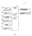
- the vehicle control apparatus 1 includes a control unit 10, a camera unit 21, a vehicle speed sensor 22, a GPS (global positioning system) receiver 23, a yaw rate sensor 24, and a map database (DB). 25, an inter-vehicle communication device 26, a vehicle control actuator 27, and a rudder angle sensor 28.
- a control unit 10 a camera unit 21, a vehicle speed sensor 22, a GPS (global positioning system) receiver 23, a yaw rate sensor 24, and a map database (DB).
- DB map database
- an inter-vehicle communication device 26 a vehicle control actuator 27, and a rudder angle sensor 28.
- the camera unit 21 is configured as a well-known camera system that images the surroundings of the host vehicle using a plurality of cameras.
- the camera unit 21 sends captured images obtained from a plurality of cameras to the control unit 10.
- the camera unit 21 is used for recognizing the position and speed of other vehicles located around the host vehicle using image processing.
- the vehicle speed sensor 22 is configured as a known vehicle speed sensor that detects the traveling speed of the host vehicle.
- the vehicle speed sensor 22 sends the detected vehicle speed to the control unit 10.
- the GPS receiver 23 is configured as a well-known GPS receiver that recognizes the position of the host vehicle by receiving radio waves transmitted from a plurality of GPS satellites.
- the GPS receiver 23 sends information on the latitude and longitude of the host vehicle to the control unit 10.
- the yaw rate sensor 24 is configured as a known yaw rate sensor that detects the turning angular velocity of the host vehicle.
- the yaw rate sensor 24 sends the detected yaw rate to the control unit 10.
- the inter-vehicle communication device 26 performs communication for exchanging position information with other vehicles located within the communicable range. That is, the inter-vehicle communication device 26 receives the information including the information (identification information such as ID) specifying the other vehicle from the other vehicle and the position information of the other vehicle while sending the position information of the own vehicle to the other vehicle.
- the inter-vehicle communication device 26 sends the obtained information to the control unit 10.
- the map DB 25 is configured as a well-known database that stores map information in which latitude and longitude are associated.
- the map DB 25 stores map data associated with latitude and longitude as used in a general navigation system.
- map information mainly indicating the surroundings of the host vehicle is read from the map DB 25.
- the vehicle control actuator 27 represents an actuator that is required when performing automatic control of the host vehicle.
- the vehicle control actuator 27 includes an actuator for controlling the accelerator opening and brake hydraulic pressure of the host vehicle, an actuator for controlling the steering state, and the like.
- the steering angle sensor 28 detects the steering angle of the host vehicle and sends the obtained information to the control unit 10.
- the control unit 10 is configured as a computer including a CPU 11 and a memory 12 such as a ROM and a RAM.
- the CPU 11 performs various processes such as a merge support process described later based on the program stored in the memory 12.
- the various processes include a process for automatically maneuvering the vehicle.
- map information from the map DB 25 to the destination is acquired and a route to the destination is set.
- the control unit 10 generates a control amount according to the actual road condition based on the image captured by the camera unit 21 and the map information, and sends an instruction to the vehicle control actuator 27 according to the control amount. Make the vehicle reach the destination.
- control amount is a parameter related to the motion necessary for controlling the motion of the host vehicle.
- control amount may include a speed, an acceleration, a turning angular velocity, an operation amount of an actuator for changing these, and the like.
- the control unit 10 performs the vehicle control process shown in FIG.
- the vehicle control process is started, for example, when the host vehicle is automatically driven, and is ended when the host vehicle is switched to manual driving.
- Ambient information indicates information related to the position and speed of other vehicles located around the host vehicle. Ambient information is obtained based on detection results of captured images, vehicle-to-vehicle communication, and other various sensors.
- map information is acquired (S130).
- the map information is obtained by reading out map data around the host vehicle from the map BD25.
- This map information includes road state information such as curvature, gradient, lane width, speed limit, etc. for each of a number of points on the road through which the vehicle passes.
- a passing target point is set (S140).
- the passing target point is set between the current location of the host vehicle and the destination, and is set within a section where the curvature of the road is constant from the current location.
- the passing target point is set to an arbitrary point in the section from the current location to 100 m ahead.
- the curvature may be regarded as constant as long as the change in the curvature is such that the steering angle can be kept constant when the lane width is fully utilized.
- a trajectory to the passing target point is generated (S150).
- the trajectory to the passing target point is defined as an arc trajectory.
- the host vehicle can be controlled to pass through an arbitrary passing target point P (x, y). Subsequently, the trajectory passing condition is calculated (S160).
- the track passing condition is a motion condition of the host vehicle for passing through the passing target point P (x, y). From the above equation [3], the objective function of control can be set as follows.
- control amount is calculated (S170).
- the control amount is obtained using the motion characteristics of the vehicle.
- the motion characteristics of the vehicle indicate characteristics and properties based on the physical motion of the vehicle, such as mechanical characteristics and vibration characteristics of the vehicle.
- Lyapunov number candidates are used, and the design is such that the one-time differentiation of Lyapunov number candidates is indefinite.
- Kf represents the cornering power of the front wheel
- lf represents the distance from the center of gravity to the front wheel
- Kr represents the cornering power of the rear wheel
- lr represents the distance from the center of gravity to the rear wheel.
- the first item in order from the left indicates the basic control amount that is a term for passing the passing target point P in the steady state, and the second and subsequent items are correction terms in the transient state. Indicates the correction control amount.
- steady running refers to running at a constant yaw rate and host vehicle speed
- steady state refers to a state of steady running.
- the transient state indicates a state that is not a steady state.
- the second item is a correction term when the yaw rate changes
- the third item is a correction term when the longitudinal acceleration changes.
- the fourth item is a correction term when the acceleration in the left-right direction changes
- the fifth item is a correction term when the speed changes.
- a command based on the calculated control amount is output to the vehicle control actuator 27 (S180).
- the host vehicle can travel along the set track.
- the control unit 10 acquires a passing target point indicating the position of a point where the host vehicle is about to pass in the future, and generates a trajectory for passing the passing target point. Moreover, the control part 10 calculates and outputs the control amount of the own vehicle for driving the own vehicle according to a track
- the passing target point that the host vehicle is about to pass in the future is set, and the host vehicle is controlled according to the trajectory passing through the passing target point.
- the correction frequency of steering can be suppressed. Therefore, riding comfort can be improved.
- the control unit 10 calculates the control amount of the host vehicle in consideration of the motion characteristics of the vehicle. According to such a vehicle control device 1, since the control amount is calculated in consideration of the motion characteristics, the vehicle can be favorably controlled according to the track.
- the control unit 10 calculates, as a basic control amount, a control amount of the host vehicle in a steady state in which the host vehicle performs steady running, and a transient state in which the host vehicle is not in steady running with respect to the basic control amount.
- the difference from the control amount of the host vehicle is calculated as a correction control amount.
- the sum of the basic control amount and the correction control amount is output as the control amount of the host vehicle.
- the control unit 10 obtains a condition for the host vehicle to travel along the track, and calculates a control amount that satisfies the condition.
- the control unit 10 generates an arc trajectory that passes through the current location of the host vehicle and the passing target point.
- various forms such as a system including the vehicle control apparatus 1 as a constituent element, a program for causing a computer to function as the vehicle control apparatus 1, a medium storing the program, a vehicle control method, etc.
- the present disclosure can also be realized.
- the process of S140 corresponds to the target point acquisition unit referred to in the present disclosure
- the process of S150 corresponds to the trajectory generation unit referred to in the present disclosure
- the process of S170 corresponds to a control amount calculation unit, a basic calculation unit, a correction calculation unit, and a control amount output unit in the present disclosure.
Landscapes
- Engineering & Computer Science (AREA)
- Transportation (AREA)
- Mechanical Engineering (AREA)
- Automation & Control Theory (AREA)
- Chemical & Material Sciences (AREA)
- Combustion & Propulsion (AREA)
- Physics & Mathematics (AREA)
- Aviation & Aerospace Engineering (AREA)
- Radar, Positioning & Navigation (AREA)
- Remote Sensing (AREA)
- General Physics & Mathematics (AREA)
- Human Computer Interaction (AREA)
- Control Of Driving Devices And Active Controlling Of Vehicle (AREA)
- Business, Economics & Management (AREA)
- Health & Medical Sciences (AREA)
- Artificial Intelligence (AREA)
- Evolutionary Computation (AREA)
- Game Theory and Decision Science (AREA)
- Medical Informatics (AREA)
- Steering Control In Accordance With Driving Conditions (AREA)
Abstract
車両制御装置において制御部は、未来において自車両が通過しようとする地点の位置を表す通過目標点を取得し(S140)、通過目標点を通過するための軌道を生成する(S150)。そして、軌道に従って自車両を走行させるための自車両の制御量を演算し出力する(S170)。
Description
本国際出願は、2015年12月4日に日本国特許庁に出願された日本国特許出願第2015-237549号に基づく優先権を主張するものであり、日本国特許出願第2015-237549号の全内容を参照により本国際出願に援用する。
本開示は、自車両の運動を制御する車両制御装置に関する。
上記の車両制御装置としては、現在において自車両が通過すべき位置と自車両の実際の位置とのずれが小さくなるように自車両の運動を制御する装置が知られている(例えば、特許文献1参照)。
ところで、山道等のカーブが多い道路では、道路形状と完全に一致するように走行するよりも、道路幅を一杯に使って緩やかに操舵を行うと乗り心地がよい。発明者の詳細な検討の結果、上記の車両制御装置では道路の曲率の変化と完全に一致することを目指して自車両の制御を行うことになるため乗り心地が悪くなるという課題が見出された。
本開示の一側面においては、自車両の運動を制御する車両制御装置においては、乗り心地を向上できるようにすることが望ましい。
本開示の一側面の車両制御装置において、目標点取得部は、未来において自車両が通過しようとする地点の位置を表す通過目標点を取得し、軌道生成部は、自車両が通過目標点を通過するための軌道を生成する。制御量演算部は、軌道に従って自車両を走行させるための自車両の制御量を演算し出力する。
本開示の一側面の車両制御装置において、目標点取得部は、未来において自車両が通過しようとする地点の位置を表す通過目標点を取得し、軌道生成部は、自車両が通過目標点を通過するための軌道を生成する。制御量演算部は、軌道に従って自車両を走行させるための自車両の制御量を演算し出力する。
このような車両制御装置によれば、未来において自車両が通過しようとする通過目標点を設定し、通過目標点を含む軌道に従って自車両を制御するので、自車両が通過目標点に到達するまでの操舵の補正頻度を抑制することができる。よって、乗り心地を向上させることができる。つまり、従来は逐次、位置誤差及び角度誤差を補正していたが、本開示の車両制御装置によれば、連続した軌道を用いて補正することができ、乗り心地を向上させることができる。
なお、各構成は、可能な限りにおいて任意に組み合わせることができる。この際、一部構成を除外してもよい。
以下に本開示にかかる実施の形態を図面と共に説明する。
[1-1.構成]
本開示が適用された車両制御装置1は、乗用車等の車両(以下、自車両という)に搭載されている。車両制御装置1は、自車両の運動を制御する機能を有しており、特に、目的地まで乗り心地を損なうことなく自車両を制御できるよう構成されている。
[1-1.構成]
本開示が適用された車両制御装置1は、乗用車等の車両(以下、自車両という)に搭載されている。車両制御装置1は、自車両の運動を制御する機能を有しており、特に、目的地まで乗り心地を損なうことなく自車両を制御できるよう構成されている。
車両制御装置1は、図1に示すように、制御部10と、カメラ部21と、車速センサ22と、GPS(全地球測位システム)受信機23と、ヨーレートセンサ24と、地図データベース(DB)25と、車車間通信装置26と、車両制御アクチュエータ27と、舵角センサ28と、を備えている。
カメラ部21は、複数のカメラを用いて自車両の周囲を撮像する周知のカメラシステムとして構成されている。カメラ部21は、複数のカメラから得られた撮像画像を制御部10に送る。なお、カメラ部21は、自車両の周囲に位置する他車両の位置や速度を、画像処理を用いて認識するために用いられる。
車速センサ22は、自車両の走行速度を検知する周知の車速センサとして構成されている。車速センサ22は、検知した車速を制御部10に送る。
GPS受信機23は、複数のGPS衛星から送信された電波を受信することによって自車両の位置を認識する周知のGPS受信機として構成されている。GPS受信機23は、自車両の緯度および経度の情報を制御部10に送る。
GPS受信機23は、複数のGPS衛星から送信された電波を受信することによって自車両の位置を認識する周知のGPS受信機として構成されている。GPS受信機23は、自車両の緯度および経度の情報を制御部10に送る。
ヨーレートセンサ24は、自車両の旋回角速度を検知する周知のヨーレートセンサとして構成されている。ヨーレートセンサ24は、検知したヨーレートを制御部10に送る。
車車間通信装置26は、通信可能範囲内に位置する他車両と位置情報を交換する通信を行う。すなわち、車車間通信装置26は、自車両の位置情報を他車両に送るとともに、他車両から他車両を特定する情報(ID等の識別情報)と他車両の位置情報とを含む情報を受ける。車車間通信装置26は、得られた情報を制御部10に送る。
車車間通信装置26は、通信可能範囲内に位置する他車両と位置情報を交換する通信を行う。すなわち、車車間通信装置26は、自車両の位置情報を他車両に送るとともに、他車両から他車両を特定する情報(ID等の識別情報)と他車両の位置情報とを含む情報を受ける。車車間通信装置26は、得られた情報を制御部10に送る。
地図DB25は、緯度および経度が対応付けられた地図情報を格納する周知のデータベースとして構成されている。地図DB25には、一般的なナビゲーションシステムにおいて用いられるような緯度および経度が対応付けられた地図データが格納されている。地図DB25からは、制御部10からの要求に応じて主として自車両の周囲を示す地図情報が読み出される。
車両制御アクチュエータ27は、自車両の自動操縦を行う際に必要となるアクチュエータを表す。例えば、車両制御アクチュエータ27には、自車両のアクセル開度やブレーキ油圧を制御するアクチュエータや、操舵状態を制御するアクチュエータ等が含まれる。
舵角センサ28は、自車両の舵角を検知し、得られた情報を制御部10に送る。
制御部10は、CPU11とROM、RAM等のメモリ12とを備えたコンピュータとして構成されている。CPU11は、メモリ12に格納されたプログラムに基づいて、後述する合流支援処理等の各種処理を実施する。
制御部10は、CPU11とROM、RAM等のメモリ12とを備えたコンピュータとして構成されている。CPU11は、メモリ12に格納されたプログラムに基づいて、後述する合流支援処理等の各種処理を実施する。
各種処理には、自車両を自動操縦する処理も含まれる。自車両を自動操縦する際には、地図DB25から目的地までの地図情報を取得して目的地までのルートを設定する。そして、制御部10は、カメラ部21による撮像画像や地図情報に基づいて、実際の道路状況に合わせた制御量を生成し、この制御量に応じて車両制御アクチュエータ27に指示を送ることによって自車両を目的地に到達させる。
なお、制御量とは、自車両の運動を制御するために必要となる運動に関するパラメータである。例えば、制御量には、速度、加速度、旋回角速度、これらを変更するためのアクチュエータの作動量等が含まれうる。
[1-2.処理]
このように構成された車両制御装置1において、制御部10は、図2に示す車両制御処理を実施する。車両制御処理は、例えば、自車両が自動運転になると開始され、その後、自車両が手動運転に切り替わると終了する。
このように構成された車両制御装置1において、制御部10は、図2に示す車両制御処理を実施する。車両制御処理は、例えば、自車両が自動運転になると開始され、その後、自車両が手動運転に切り替わると終了する。
車両制御処理では、図2に示すように、まず、カメラ部21による撮像画像を取得する(S110)。続いて、周囲情報を検出する(S120)。周囲情報とは、自車両の周囲に位置する他車両の位置や速度に関する情報を示す。周囲情報は、撮像画像や車車間通信、その他の各種センサによる検出結果に基づいて得られる。
続いて、地図情報を取得する(S130)。地図情報は、地図BD25から自車両の周囲の地図データを読み出すことによって得られる。この地図情報には、自車両が通過する道路の多数の地点毎に、曲率、勾配、車線幅、制限速度等の道路状態情報が含まれる。
続いて、通過目標点を設定する(S140)。通過目標点は、自車両の現在地から目的地までの間であって、現在地から少なくとも道路の曲率が一定の区間内において設定される。
例えば、自車両がこれから100m先まで曲率が一定の道路を走行する場合には、通過目標点は現在地から100m先までの区間内において任意の地点に設定される。なお、道路の曲率は完全に一定でなくても、車線幅をいっぱいに利用した際に舵角が一定のまま通過できる程度の曲率の変化であれば曲率が一定とみなしてもよい。
続いて、通過目標点までの軌道を生成する(S150)。ここで、図3に示すように、自車両の現在地をOvhclとし、通過目標点をP(x、y)とする。そして、通過目標点までの軌道を円弧軌道とする。
より詳細に述べると、自車両のヨーレートγ、すべり角β、速度vとの関係は、下記の式[1]にて示すことができる。

ただし、ψは絶対座標基準の方位角を示す。自車両の将来の軌道を表す軌道方程式は、以下のようになる。

この式[2]を変形すると、以下のように記述できる。

式[3]にて示す関係式を満たせば、任意の通過目標点P(x、y)を通過するよう自車両を制御できる。
続いて、軌道通過条件を算出する(S160)。軌道通過条件とは、通過目標点P(x、y)を通過するための自車両の運動条件である。上記式[3]より、制御の目的関数を以下のように設定することができる。
続いて、軌道通過条件を算出する(S160)。軌道通過条件とは、通過目標点P(x、y)を通過するための自車両の運動条件である。上記式[3]より、制御の目的関数を以下のように設定することができる。

この式[4]においてu→0とすることで、通過目標点Pを通過するよう自車両を制御できる。つまり、任意の手法を用いて、u=0となるように自車両のヨーレートγ、すべり角β、速度vを設定すればよい。
続いて、制御量を演算する(S170)。ここでは、車両の運動特性を利用して制御量を求める。車両の運動特性とは、車両の機械的特性や振動特性等、車両の物理運動に基づく特徴や性質を示す。
ここではまず、リアプノフ間数候補を利用し、リアプノフ間数候補の1回微分が不定となるよう設計する。

このとき、自車両の運動特性に基づく運動方程式を考慮する。

ここで、実装上の容易さ、センサ値の信頼性、主に乗用車に適用されること等の諸事情を勘案して、βとβの一回微分を0とすると、式[4][5]より下記式[7]が得られる。

上記式[7]において式[6]を考慮すると、舵角δは、以下の式[8]にて得られる。

なお、式[8]中のa11は以下にて示すことができる。

ただし、式[9]中において、Kfは前輪のコーナリングパワーを示し、lfは重心点から前輪までの距離を示す。また、Krは後輪のコーナリングパワーを示し、lrは重心点から後輪までの距離を示す。
式[8]の右辺において、左から順に第1項目は、定常状態において通過目標点Pを通過させるための項である基礎制御量を示し、第2項目以降は、過渡状態における補正項である補正制御量を示す。
なお、定常走行とは、ヨーレートおよび自車両の速度が一定での走行を示し、定常状態とは定常走行をしている状態を示す。また、過渡状態とは、定常状態でない状態を示す。
第2項目は、ヨーレートが変化する際の補正項であり、第3項目は、前後方向の加速度が変化する際の補正項である。第4項目は、左右方向の加速度が変化する際の補正項であり、第5項目は、速度が変化する際の補正項である。
第2項目は、ヨーレートが変化する際の補正項であり、第3項目は、前後方向の加速度が変化する際の補正項である。第4項目は、左右方向の加速度が変化する際の補正項であり、第5項目は、速度が変化する際の補正項である。
続いて、演算された制御量に基づく指令を車両制御アクチュエータ27に出力する(S180)。この処理によって、自車両は設定された軌道に沿って走行し得る。
続いて、自動運転による車両制御が終了したか否かを判定する(S190)。車両制御が終了していなければ(S190:NO)、S110の処理に戻る。また、車両制御が終了していれば(S190):YES)、車両制御処理を終了する。
続いて、自動運転による車両制御が終了したか否かを判定する(S190)。車両制御が終了していなければ(S190:NO)、S110の処理に戻る。また、車両制御が終了していれば(S190):YES)、車両制御処理を終了する。
[1-3.効果]
上記の車両制御装置1において制御部10は、未来において自車両が通過しようとする地点の位置を表す通過目標点を取得し、通過目標点を通過するための軌道を生成する。また、制御部10は、軌道に従って自車両を走行させるための自車両の制御量を演算し出力する。
上記の車両制御装置1において制御部10は、未来において自車両が通過しようとする地点の位置を表す通過目標点を取得し、通過目標点を通過するための軌道を生成する。また、制御部10は、軌道に従って自車両を走行させるための自車両の制御量を演算し出力する。
このような車両制御装置1によれば、未来において自車両が通過しようとする通過目標点を設定し、通過目標点を通過する軌道に従って自車両を制御するので、通過目標点に到達するまでの操舵の補正頻度を抑制することができる。よって、乗り心地を向上させることができる。
上記の車両制御装置1において制御部10は、車両における運動特性を加味して前記自車両の制御量を演算する。
このような車両制御装置1によれば、運動特性を加味して制御量を演算するので、車両を軌道に従って良好に制御することができる。
このような車両制御装置1によれば、運動特性を加味して制御量を演算するので、車両を軌道に従って良好に制御することができる。
上記の車両制御装置1において制御部10は、自車両が定常走行を行う定常状態における自車両の制御量を基礎制御量として演算し、基礎制御量に対して、自車両が定常走行でない過渡状態における自車両の制御量との差分を補正制御量として演算する。そして、基礎制御量と補正制御量との和を自車両の制御量として出力する。
このような車両制御装置1によれば、定常状態における基礎制御量を過渡状態における補正制御量で補正する構成とするので、演算を簡素化することができる。
上記の車両制御装置1において制御部10は、軌道に沿って自車両が走行するための条件を求め、この条件を満たす制御量を演算する。
上記の車両制御装置1において制御部10は、軌道に沿って自車両が走行するための条件を求め、この条件を満たす制御量を演算する。
このような車両制御装置1によれば、求めた軌道に従って自車両を走行させやすくすることができる。
上記の車両制御装置1において制御部10は、自車両の現在地と通過目標点とを通過する円弧軌道を生成する。
上記の車両制御装置1において制御部10は、自車両の現在地と通過目標点とを通過する円弧軌道を生成する。
このような車両制御装置1によれば、自車両が走行すべき軌道として円弧軌道を生成するので、簡素な演算にて乗り心地よく自車両を制御することができる。
[2.その他の実施形態]
本開示は、上記の実施形態によって何ら限定して解釈されない。また、上記の実施形態の説明で用いる符号を特許請求の範囲にも適宜使用しているが、各側面に係る開示の理解を容易にする目的で使用しており、各側面に係る開示の技術的範囲を限定する意図ではない。上記実施形態における1つの構成要素が有する機能を複数の構成要素として分散させたり、複数の構成要素が有する機能を1つの構成要素に統合させたりしてもよい。また、上記実施形態の構成の一部を、課題を解決できる限りにおいて省略してもよい。また、上記実施形態の構成の少なくとも一部を、他の上記実施形態の構成に対して付加又は置換してもよい。なお、特許請求の範囲に記載した文言のみによって特定される技術思想に含まれるあらゆる態様が本開示の実施形態である。
[2.その他の実施形態]
本開示は、上記の実施形態によって何ら限定して解釈されない。また、上記の実施形態の説明で用いる符号を特許請求の範囲にも適宜使用しているが、各側面に係る開示の理解を容易にする目的で使用しており、各側面に係る開示の技術的範囲を限定する意図ではない。上記実施形態における1つの構成要素が有する機能を複数の構成要素として分散させたり、複数の構成要素が有する機能を1つの構成要素に統合させたりしてもよい。また、上記実施形態の構成の一部を、課題を解決できる限りにおいて省略してもよい。また、上記実施形態の構成の少なくとも一部を、他の上記実施形態の構成に対して付加又は置換してもよい。なお、特許請求の範囲に記載した文言のみによって特定される技術思想に含まれるあらゆる態様が本開示の実施形態である。
上述した車両制御装置1の他、当該車両制御装置1を構成要素とするシステム、当該車両制御装置1としてコンピュータを機能させるためのプログラム、このプログラムを記録した媒体、車両制御方法など、種々の形態で本開示を実現することもできる。
[3.実施形態の構成と本開示の手段との対応関係]
上記実施形態において制御部10が実行する処理のうちのS140の処理は本開示でいう目標点取得部に相当し、上記実施形態においてS150の処理は本開示でいう軌道生成部に相当する。また、上記実施形態において、S170の処理は本開示でいう制御量演算部、基礎演算部、補正演算部、および制御量出力部に相当する。
上記実施形態において制御部10が実行する処理のうちのS140の処理は本開示でいう目標点取得部に相当し、上記実施形態においてS150の処理は本開示でいう軌道生成部に相当する。また、上記実施形態において、S170の処理は本開示でいう制御量演算部、基礎演算部、補正演算部、および制御量出力部に相当する。
Claims (5)
- 自車両に搭載され、自車両の運動を制御する車両制御装置(10)であって、未来において自車両が通過しようとする地点の位置を表す通過目標点を取得する目標点取得部(S140)と、自車両が前記通過目標点を通過するための軌道を生成する軌道生成部(S150)と、前記軌道に従って自車両を走行させるための自車両の制御量を演算し出力する制御量演算部(S170)と、を備える車両制御装置。
- 請求項1に記載の車両制御装置において、前記制御量演算部は、車両における運動特性を加味して前記自車両の制御量を演算する車両制御装置。
- 請求項1または請求項2に記載の車両制御装置において、前記制御量演算部は、自車両が定常走行を行う定常状態における自車両の制御量を基礎制御量として演算する基礎演算部(S170:数8)と、前記基礎制御量に対して、自車両が定常走行でない過渡状態における自車両の制御量との差分を補正制御量として演算する補正演算部(S170:数8)と、前記基礎制御量と前記補正制御量との和を前記自車両の制御量として出力する制御量出力部(S170:数8)と、を備える車両制御装置。
- 請求項1~請求項3の何れか1項に記載の車両制御装置において、前記制御量演算部は、前記軌道に沿って自車両が走行するための条件を求め、該条件を満たす制御量を演算する車両制御装置。
- 請求項1~請求項4の何れか1項に記載の車両制御装置において、前記軌道生成部は、前記軌道として、自車両の現在地と前記通過目標点とを通過する円弧軌道を生成する車両制御装置。
Priority Applications (1)
| Application Number | Priority Date | Filing Date | Title |
|---|---|---|---|
| US15/780,427 US20180348776A1 (en) | 2015-12-04 | 2016-12-02 | Vehicle control device |
Applications Claiming Priority (2)
| Application Number | Priority Date | Filing Date | Title |
|---|---|---|---|
| JP2015-237549 | 2015-12-04 | ||
| JP2015237549A JP6589608B2 (ja) | 2015-12-04 | 2015-12-04 | 車両制御装置 |
Publications (1)
| Publication Number | Publication Date |
|---|---|
| WO2017094908A1 true WO2017094908A1 (ja) | 2017-06-08 |
Family
ID=58797427
Family Applications (1)
| Application Number | Title | Priority Date | Filing Date |
|---|---|---|---|
| PCT/JP2016/085971 Ceased WO2017094908A1 (ja) | 2015-12-04 | 2016-12-02 | 車両制御装置 |
Country Status (3)
| Country | Link |
|---|---|
| US (1) | US20180348776A1 (ja) |
| JP (1) | JP6589608B2 (ja) |
| WO (1) | WO2017094908A1 (ja) |
Citations (6)
| Publication number | Priority date | Publication date | Assignee | Title |
|---|---|---|---|---|
| JP2008149855A (ja) * | 2006-12-15 | 2008-07-03 | Toyota Motor Corp | 車両の目標進路変更軌跡生成装置 |
| JP2009061878A (ja) * | 2007-09-05 | 2009-03-26 | Toyota Motor Corp | 走行制御装置 |
| WO2011086684A1 (ja) * | 2010-01-15 | 2011-07-21 | トヨタ自動車株式会社 | 車両制御装置 |
| WO2012131952A1 (ja) * | 2011-03-30 | 2012-10-04 | トヨタ自動車株式会社 | 車両の駆動力制御装置 |
| JP2013112067A (ja) * | 2011-11-25 | 2013-06-10 | Toyota Motor Corp | 走行進路生成装置および走行制御装置 |
| JP5561385B2 (ja) * | 2012-01-25 | 2014-07-30 | 株式会社デンソー | 逸脱抑制装置および逸脱抑制プログラム |
Family Cites Families (16)
| Publication number | Priority date | Publication date | Assignee | Title |
|---|---|---|---|---|
| JP2010076697A (ja) * | 2008-09-29 | 2010-04-08 | Advics Co Ltd | 車両の速度制御装置 |
| DE102009047476A1 (de) * | 2009-12-04 | 2011-06-09 | Robert Bosch Gmbh | Verfahren und Steuergerät zur Bestimmung einer Schnitttrajektorie eines Kurvenabschnitts einer Fahrbahn |
| JP5601224B2 (ja) * | 2010-03-04 | 2014-10-08 | 株式会社デンソー | 道路形状学習装置 |
| JP5516146B2 (ja) * | 2010-06-30 | 2014-06-11 | トヨタ自動車株式会社 | 車両の走行制御装置 |
| JP5783204B2 (ja) * | 2013-05-01 | 2015-09-24 | トヨタ自動車株式会社 | 運転支援装置および運転支援方法 |
| JP6281405B2 (ja) * | 2014-05-12 | 2018-02-21 | 株式会社デンソー | 運転支援装置 |
| US9428187B2 (en) * | 2014-06-05 | 2016-08-30 | GM Global Technology Operations LLC | Lane change path planning algorithm for autonomous driving vehicle |
| US9457807B2 (en) * | 2014-06-05 | 2016-10-04 | GM Global Technology Operations LLC | Unified motion planning algorithm for autonomous driving vehicle in obstacle avoidance maneuver |
| US9227635B1 (en) * | 2014-09-25 | 2016-01-05 | Nissan North America, Inc. | Method and system of assisting a driver of a vehicle |
| JP2017100652A (ja) * | 2015-12-04 | 2017-06-08 | 株式会社デンソー | 走行軌跡生成装置、走行軌跡生成方法 |
| JP6512084B2 (ja) * | 2015-12-04 | 2019-05-15 | 株式会社デンソー | 走行軌跡生成装置、走行軌跡生成方法 |
| JP6642331B2 (ja) * | 2016-08-23 | 2020-02-05 | 株式会社デンソー | 運転支援制御装置 |
| US20190308625A1 (en) * | 2016-11-29 | 2019-10-10 | Mazda Motor Corporation | Vehicle control device |
| JP2018136700A (ja) * | 2017-02-21 | 2018-08-30 | トヨタ自動車株式会社 | 車両の制御装置 |
| JP6485792B2 (ja) * | 2017-03-17 | 2019-03-20 | マツダ株式会社 | 運転支援制御装置 |
| US10239451B1 (en) * | 2017-09-05 | 2019-03-26 | GM Global Technology Operations LLC | Systems and methods for providing relative lane assignment of objects at distances from the vehicle |
-
2015
- 2015-12-04 JP JP2015237549A patent/JP6589608B2/ja not_active Expired - Fee Related
-
2016
- 2016-12-02 WO PCT/JP2016/085971 patent/WO2017094908A1/ja not_active Ceased
- 2016-12-02 US US15/780,427 patent/US20180348776A1/en not_active Abandoned
Patent Citations (6)
| Publication number | Priority date | Publication date | Assignee | Title |
|---|---|---|---|---|
| JP2008149855A (ja) * | 2006-12-15 | 2008-07-03 | Toyota Motor Corp | 車両の目標進路変更軌跡生成装置 |
| JP2009061878A (ja) * | 2007-09-05 | 2009-03-26 | Toyota Motor Corp | 走行制御装置 |
| WO2011086684A1 (ja) * | 2010-01-15 | 2011-07-21 | トヨタ自動車株式会社 | 車両制御装置 |
| WO2012131952A1 (ja) * | 2011-03-30 | 2012-10-04 | トヨタ自動車株式会社 | 車両の駆動力制御装置 |
| JP2013112067A (ja) * | 2011-11-25 | 2013-06-10 | Toyota Motor Corp | 走行進路生成装置および走行制御装置 |
| JP5561385B2 (ja) * | 2012-01-25 | 2014-07-30 | 株式会社デンソー | 逸脱抑制装置および逸脱抑制プログラム |
Also Published As
| Publication number | Publication date |
|---|---|
| US20180348776A1 (en) | 2018-12-06 |
| JP2017100658A (ja) | 2017-06-08 |
| JP6589608B2 (ja) | 2019-10-16 |
Similar Documents
| Publication | Publication Date | Title |
|---|---|---|
| CN106476883B (zh) | 车辆的行驶控制装置 | |
| CN111066071B (zh) | 驾驶辅助车辆的位置误差校正方法及位置误差校正装置 | |
| US9796416B2 (en) | Automated driving apparatus and automated driving system | |
| CN110877611B (zh) | 障碍物回避装置及障碍物回避路径生成装置 | |
| CN107054361A (zh) | 车辆的转向控制装置 | |
| US20160318513A1 (en) | Real-time anticipatory speed control | |
| EP3243686B1 (en) | Target route generation device and drive control device | |
| WO2017094849A1 (ja) | 車両制御装置 | |
| WO2017077794A1 (ja) | 車両の走行支援装置 | |
| JP7106872B2 (ja) | 車両の自動運転制御装置及び自動運転制御方法 | |
| US20200307612A1 (en) | Vehicle control device | |
| JP2017030396A (ja) | 車両の走行制御装置 | |
| US20180347993A1 (en) | Systems and methods for verifying road curvature map data | |
| EP3626570B1 (en) | Driving assistance method and driving assistance apparatus | |
| JP7332785B2 (ja) | 車両制御装置 | |
| JP6614112B2 (ja) | 前照灯制御装置 | |
| JP7602614B2 (ja) | 車両制御装置、車両制御方法、および車両制御システム | |
| CN118046919A (zh) | 用于自动驾驶的超前控制方法 | |
| JP4899626B2 (ja) | 走行制御装置 | |
| JP2026002571A (ja) | 表示装置 | |
| JP6589608B2 (ja) | 車両制御装置 | |
| JP2023049571A (ja) | 操舵制御方法及び操舵制御装置 | |
| JP6784633B2 (ja) | 車両の走行制御装置 | |
| US20250304155A1 (en) | Steering interventions for vehicles | |
| US20250296627A1 (en) | Steering interventions for vehicles |
Legal Events
| Date | Code | Title | Description |
|---|---|---|---|
| 121 | Ep: the epo has been informed by wipo that ep was designated in this application |
Ref document number: 16870843 Country of ref document: EP Kind code of ref document: A1 |
|
| NENP | Non-entry into the national phase |
Ref country code: DE |
|
| 122 | Ep: pct application non-entry in european phase |
Ref document number: 16870843 Country of ref document: EP Kind code of ref document: A1 |