WO2017090344A1 - 光走査装置の透明カバー部の清掃機構及び該清掃機構を備えた光走査装置 - Google Patents
光走査装置の透明カバー部の清掃機構及び該清掃機構を備えた光走査装置 Download PDFInfo
- Publication number
- WO2017090344A1 WO2017090344A1 PCT/JP2016/080854 JP2016080854W WO2017090344A1 WO 2017090344 A1 WO2017090344 A1 WO 2017090344A1 JP 2016080854 W JP2016080854 W JP 2016080854W WO 2017090344 A1 WO2017090344 A1 WO 2017090344A1
- Authority
- WO
- WIPO (PCT)
- Prior art keywords
- spiral groove
- screw shaft
- cleaning mechanism
- optical scanning
- scanning device
- Prior art date
- Legal status (The legal status is an assumption and is not a legal conclusion. Google has not performed a legal analysis and makes no representation as to the accuracy of the status listed.)
- Ceased
Links
Images






Classifications
-
- B—PERFORMING OPERATIONS; TRANSPORTING
- B41—PRINTING; LINING MACHINES; TYPEWRITERS; STAMPS
- B41J—TYPEWRITERS; SELECTIVE PRINTING MECHANISMS, i.e. MECHANISMS PRINTING OTHERWISE THAN FROM A FORME; CORRECTION OF TYPOGRAPHICAL ERRORS
- B41J2/00—Typewriters or selective printing mechanisms characterised by the printing or marking process for which they are designed
- B41J2/435—Typewriters or selective printing mechanisms characterised by the printing or marking process for which they are designed characterised by selective application of radiation to a printing material or impression-transfer material
- B41J2/47—Typewriters or selective printing mechanisms characterised by the printing or marking process for which they are designed characterised by selective application of radiation to a printing material or impression-transfer material using the combination of scanning and modulation of light
-
- G—PHYSICS
- G02—OPTICS
- G02B—OPTICAL ELEMENTS, SYSTEMS OR APPARATUS
- G02B26/00—Optical devices or arrangements for the control of light using movable or deformable optical elements
- G02B26/08—Optical devices or arrangements for the control of light using movable or deformable optical elements for controlling the direction of light
- G02B26/10—Scanning systems
-
- G—PHYSICS
- G02—OPTICS
- G02B—OPTICAL ELEMENTS, SYSTEMS OR APPARATUS
- G02B26/00—Optical devices or arrangements for the control of light using movable or deformable optical elements
- G02B26/08—Optical devices or arrangements for the control of light using movable or deformable optical elements for controlling the direction of light
- G02B26/10—Scanning systems
- G02B26/12—Scanning systems using multifaceted mirrors
-
- G—PHYSICS
- G03—PHOTOGRAPHY; CINEMATOGRAPHY; ANALOGOUS TECHNIQUES USING WAVES OTHER THAN OPTICAL WAVES; ELECTROGRAPHY; HOLOGRAPHY
- G03G—ELECTROGRAPHY; ELECTROPHOTOGRAPHY; MAGNETOGRAPHY
- G03G15/00—Apparatus for electrographic processes using a charge pattern
- G03G15/04—Apparatus for electrographic processes using a charge pattern for exposing, i.e. imagewise exposure by optically projecting the original image on a photoconductive recording material
-
- H—ELECTRICITY
- H04—ELECTRIC COMMUNICATION TECHNIQUE
- H04N—PICTORIAL COMMUNICATION, e.g. TELEVISION
- H04N1/00—Scanning, transmission or reproduction of documents or the like, e.g. facsimile transmission; Details thereof
- H04N1/04—Scanning arrangements, i.e. arrangements for the displacement of active reading or reproducing elements relative to the original or reproducing medium, or vice versa
- H04N1/113—Scanning arrangements, i.e. arrangements for the displacement of active reading or reproducing elements relative to the original or reproducing medium, or vice versa using oscillating or rotating mirrors
Definitions
- the present invention relates to a cleaning mechanism for a transparent cover portion of an optical scanning device and an optical scanning device provided with the cleaning mechanism.
- An image forming apparatus that employs an electrophotographic system such as a copying machine or a printer includes an optical scanning device that emits light for forming an electrostatic latent image on a photosensitive member, and an electrostatic latent image formed on the photosensitive member. And a developing device for developing as an image.
- the optical scanning device has a housing that houses a polygon mirror, an imaging lens, and the like.
- the housing is formed with an emission port through which light is emitted.
- the emission port is closed by a cover part such as transparent dustproof glass.
- Patent Document 1 discloses a cleaning mechanism that periodically cleans the surface of dust-proof glass.
- the cleaning mechanism of Patent Document 1 has a screw shaft arranged along dust-proof glass, a holding member screwed to the screw shaft, and a cleaning member held by the holding member.
- a protrusion that engages with the screw groove of the screw shaft is formed on the inner peripheral surface of the holding member. Then, by rotating the screw shaft forward and backward, the cleaning member is reciprocated along the dust-proof glass together with the holding member to clean the surface of the dust-proof glass.
- a motor for rotating the screw shaft forward and backward is housed inside the optical scanning device, and the power of the motor is transmitted to the screw shaft through a plurality of gears.
- the optical scanning device disclosed in Patent Document 1 has a problem in that the optical scanning device is provided with a dedicated motor for rotating the screw shaft, which increases the size and cost of the optical scanning device.
- the motor for rotating the screw shaft is also used as an external motor (for example, a conveyance motor) mounted on the image forming apparatus.
- the present invention has been made in view of the above points, and an object of the present invention is to perform optical scanning that can reciprocate a holding member along the screw shaft without rotating the screw shaft in both forward and reverse directions.
- An object of the present invention is to provide a cleaning mechanism for the transparent cover portion of the apparatus.
- the present invention is directed to a cleaning mechanism for the transparent cover portion of an optical scanning device having a housing in which a light emission port is formed and a transparent cover portion for closing the light emission port.
- the cleaning mechanism includes a screw shaft, a bearing portion, a holding member, and a cleaning member.
- the screw shaft is disposed along the transparent cover portion, and a spiral groove portion is formed on the peripheral surface.
- the bearing portion is provided in the housing and rotatably supports the screw shaft.
- the holding member is formed with an engaging portion that engages with a groove portion of the screw shaft.
- the holding member is configured to move along the screw shaft as the screw shaft rotates.
- the cleaning member is held by the holding member, and cleans the surface of the transparent cover part by moving the holding member.
- the groove includes a first spiral groove and a second spiral groove whose lead angles are opposite to each other and intersect each other, and the engagement portion includes a first protrusion and a first protrusion that engage with the first spiral groove. A second protrusion engaging the two helical grooves.
- the holding member can be reciprocated along the screw shaft without rotating the screw shaft in both forward and reverse directions.
- FIG. 1 is a schematic configuration diagram illustrating an image forming apparatus equipped with an optical scanning device having a cleaning mechanism in the embodiment.
- FIG. 2 is an external perspective view of the optical scanning device.
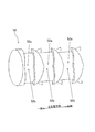
- FIG. 3 is a schematic view showing an internal structure in the housing body of the optical scanning device.
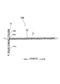
- FIG. 4 is a plan view showing the automatic cleaning unit.
- FIG. 5 is a view in the direction of the arrow V in FIG. 6 is a view in the direction of the arrow VI in FIG.
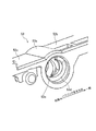
- FIG. 7 is an enlarged perspective view showing an end portion of the screw shaft.
- FIG. 8 is an enlarged perspective view showing the cylindrical nut portion of the holding member and its periphery in an enlarged manner.
- FIG. 9 is a cross-sectional view of the cylindrical nut portion of the holding member cut along the axis.
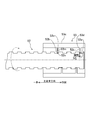
- FIG. 10 is a cross-sectional view of the automatic cleaning unit cut along the axis of the cylindrical nut unit, and shows a state where the holding member is moving from one side to the other side in the main scanning direction.
- FIG. 11 is a cross-sectional view of the automatic cleaning portion cut along the axis of the cylindrical nut portion, showing a state in which the holding member is moving from the other side in the main scanning direction toward one side.
- FIG. 1 is a schematic configuration diagram of an image forming apparatus 1 according to an embodiment of the present invention.
- the front side and the rear side mean the front side and the rear side (the front side and the rear side in the direction perpendicular to the paper surface in FIG. 1)
- the left side and the right side refer to the image forming apparatus 1 from the front side. It means the left side and the right side when viewed.
- the image forming apparatus 1 is a tandem type color printer, and includes an image forming unit 3 in a box-shaped casing 2.
- the image forming unit 3 transfers and forms an image on the recording paper P based on image data transmitted from an external device such as a computer connected to a network.
- An optical scanning device 4 that emits laser light is disposed below the image forming unit 3, and a transfer belt 5 is disposed above the image forming unit 3.
- a paper storage unit 6 that stores the recording paper P is disposed below the optical scanning device 4, and a manual paper feed unit 7 is disposed on the left side of the paper storage unit 6.
- a fixing unit 8 that performs a fixing process on an image transferred and formed on the recording paper P is disposed.
- Reference numeral 9 denotes a paper discharge unit that is disposed on the casing 2 and discharges the recording paper P that has been subjected to fixing processing by the fixing unit 8.
- the image forming unit 3 includes four image forming units 10 arranged in a line along the transfer belt 5. These image forming units 10 have a photosensitive drum 11. A charger 12 is disposed immediately below each photoconductive drum 11, a developing device 13 is disposed on the left side of each photoconductive drum 11, and a primary transfer roller 14 is disposed directly above each photoconductive drum 11. A cleaning unit 15 for cleaning the peripheral surface of the photoconductive drum 11 is disposed on the right side of each photoconductive drum 11.
- Each photosensitive drum 11 is charged with a constant peripheral surface by a charger 12, and the laser corresponding to each color based on image data input from the computer or the like is applied to the peripheral surface of the photosensitive drum 11 after charging.
- Light is irradiated from the optical scanning device 4, and an electrostatic latent image is formed on the peripheral surface of each photosensitive drum 11.
- Developer is supplied to the electrostatic latent image from the developing device 13, and a yellow, magenta, cyan, or black toner image is formed on the peripheral surface of each photosensitive drum 11.
- These toner images are respectively transferred to the transfer belt 5 by a transfer bias applied to the primary transfer roller 14.
- Reference numeral 16 denotes a secondary transfer roller disposed in contact with the transfer belt 5 below the fixing unit 8, and is recorded on the sheet conveyance path 17 from the sheet storage unit 6 or the manual sheet feeding unit 7.
- the paper P is sandwiched between the secondary transfer roller 16 and the transfer belt 5, and the toner image on the transfer belt 5 is transferred to the recording paper P by the transfer bias applied to the secondary transfer roller 16.
- the fixing unit 8 includes a heating roller 18 and a pressure roller 19.
- the toner image transferred onto the recording paper P is heated by holding the recording paper P between the heating roller 18 and the pressure roller 19 while being pressed. Is fixed to the recording paper P.
- the recording paper P after the fixing process is discharged to the paper discharge unit 9.
- Reference numeral 20 denotes a reversing conveyance path for reversing the recording paper P discharged from the fixing unit 8 during double-sided printing.
- FIG. 2 is an external perspective view of the optical scanning device 4.
- the optical scanning device 4 includes a sealed box-shaped housing 40.
- the housing 40 includes a bottomed box-shaped housing main body 41 that opens on the ceiling side, and a lid member 42 that closes the ceiling side of the housing main body 41.
- FIG. 3 is a cross-sectional view showing a state in which the lid member 42 is removed from the housing 40 of the optical scanning device 4.
- a polygon mirror 43 and a drive motor 44 that rotationally drives the polygon mirror 43 are disposed at the center of the bottom wall portion of the housing body 41.
- the polygon mirror 43 deflects and scans a laser beam for writing an electrostatic latent image corresponding to each color of magenta (M), cyan (C), yellow (Y), and black (K) emitted from a light source.
- a total of four scanning optical systems S are arranged on the bottom wall of the housing body 41, two on each side of the polygon mirror 43.
- the four scanning optical systems S guide laser beams corresponding to the respective colors of magenta (M), cyan (C), yellow (Y), and black (K) to the surface of each photosensitive drum 11.
- These scanning optical systems S are composed of, for example, an f ⁇ lens, a reflection mirror, and the like.
- the lid member 42 is formed with four rectangular exit ports 45 through which the laser beams emitted from the respective scanning optical systems S pass. These emission openings 45 are covered with a transparent dustproof glass (transparent cover part) 46 that transmits light. Each emission port 45 and each dustproof glass 46 covering them are formed in a rectangular plate shape that is long in the main scanning direction.
- the surface of each dustproof glass 46 is automatically cleaned by an automatic cleaning mechanism 50.
- the automatic cleaning mechanism 50 includes a first automatic cleaning unit 50A and a second automatic cleaning unit 50B.
- the first automatic cleaning unit 50A and the second automatic cleaning unit 50B are arranged symmetrically with respect to the center position in the longitudinal direction of the housing 40.
- the first automatic cleaning section 50A cleans the two dustproof glasses 46 through which the magenta (M) and cyan (C) laser beams pass.
- the second automatic cleaning unit 50B cleans the two dustproof glasses 46 through which the yellow (Y) and black (K) laser beams pass.
- the first automatic cleaning unit 50A and the second automatic cleaning unit 50B are driven by a common drive motor 60 (shown only in FIG. 1). In the present embodiment, the drive motor 60 is configured separately from the optical scanning device 4 as described later.
- each of the automatic cleaning units 50 ⁇ / b> A and 50 ⁇ / b> B includes a screw shaft 52 and a holding member 53 that is reciprocally driven by the screw shaft 52. And a pair of cleaning members 51 (shown only in FIG. 5) held by the holding member 53.
- the screw shaft 52 is disposed so as to extend in the main scanning direction. Both ends in the axial direction of the screw shaft 52 are rotatably supported by bearings (not shown) formed on the lid member 42 of the housing 40.
- a drive gear 55 (shown only in FIG. 2) is attached to one end of the screw shaft 52.
- the drive gear 55 meshes with an idle gear 56 supported on the side wall surface of the housing body 41.
- the idle gear 56 is connected to a drive motor 60 (see FIG. 1) via a gear mechanism provided in the image forming apparatus 1 when the optical scanning device 4 is assembled at a predetermined position of the image forming apparatus 1. .
- the drive motor 60 has both a function of driving the automatic cleaning units 50A and 50B of the optical scanning device 4 and a function of driving a paper transport roller in the image forming apparatus 1. That is, the drive motor 60 that drives each of the automatic cleaning units 50A and 50B is also used as the drive motor 60 for the paper transport roller provided in the image forming apparatus 1.
- the drive motor 60 is configured to be rotatable only in one direction (forward rotation direction).
- a groove is formed on the outer peripheral surface of the screw shaft 52.
- the groove portion includes a first spiral groove 52a and a second spiral groove 52b.
- the first spiral groove 52 a and the second spiral groove 52 b are formed in a spiral shape around a common axis along the outer peripheral surface of the screw shaft 52.
- the axis of the screw shaft 52 and the axis of each of the spiral grooves 52a and 52b coincide.
- the first spiral groove 52 a and the second spiral groove 52 b are formed over the entire axial direction of the screw shaft 52.
- the first spiral groove 52 a and the second spiral groove 52 b intersect in an X shape when viewed from the radial direction of the screw shaft 52. That is, the first spiral groove 52a and the second spiral groove 52b are formed such that the lead angles are in opposite phases.
- the absolute value of the lead angle of the first spiral groove 52a is equal to the absolute value of the lead angle of the second spiral groove 52b.
- one side ends of the first spiral groove 52 a and the second spiral groove 52 b in the spiral axis direction are continuous at one side end of the screw shaft 52.
- the other end portions of the first spiral groove 52a and the second spiral groove 52b in the spiral axis direction are the other end portions of the screw shaft 52 (not shown in FIG. 7). ) Are connected continuously.
- the holding member 53 has a cylindrical nut portion 53a, a first holding plate portion 53b, and a second holding plate portion 53c.
- the cylindrical nut portion 53 a is formed in a substantially cylindrical shape and is externally attached to the screw shaft 52.
- On the inner peripheral surface of the cylindrical nut portion 53a there are a first spiral protrusion (corresponding to the first protrusion) 53d as an engaging portion that engages with the first spiral groove 52a, and a second spiral groove 52b.
- a second spiral protrusion (corresponding to the second protrusion) 53e is formed as an engaging portion to be engaged.
- the first spiral protrusion 53d and the second spiral protrusion 53e protrude radially inward from the inner peripheral surface of the cylindrical nut portion 53a. As shown in FIG. 9, the first spiral protrusion 53d and the second spiral protrusion 53e are formed such that the lead angles are in opposite phases.
- the absolute value of the lead angle of the first spiral protrusion 53d is equal to the absolute value of the lead angle of the second spiral protrusion 53e.
- the first holding plate portion 53b extends from the upper end portion of the cylindrical nut portion 53a to one side of the housing longitudinal direction
- the second holding plate portion 53c extends from the upper end portion of the cylindrical nut portion 53a to the other side of the housing longitudinal direction. Extends to the side.
- the cleaning members 51 are attached to the lower surfaces of the first holding plate portion 53b and the second holding plate portion 53c, respectively.
- Each cleaning member 51 is formed of an elastic blade member (for example, a silicon pad). Each cleaning member 51 is provided at a position corresponding to a pair of dustproof glasses 46 to be cleaned by each automatic cleaning unit 50A, 50B. That is, each cleaning member 51 is provided at a position overlapping each dustproof glass 46 in plan view. Each cleaning member 51 is sandwiched between the holding plate portions 53b and 53c and the dust-proof glass 46 and compressed with a light load in the thickness direction. Thereby, each cleaning member 51 is pressed against the dust-proof glass 46 with a predetermined pressing force.
- an elastic blade member for example, a silicon pad
- the screw shaft 52 is rotated in the forward direction (in the direction indicated by the two-dot chain line in the figure and the other side in the main scanning direction) by the drive motor 60 (shown only in FIG. 1). (Clockwise as viewed from the side). As the screw shaft 52 rotates, the holding member 53 reciprocates in the main scanning direction (the axial direction of the screw shaft 52).
- the groove side surface 52j of the first spiral groove 52a contacts the side surface 53k of the first spiral protrusion 53d. Touch.
- the side surface 53k of the first spiral protrusion 53d of the holding member 53 is moved from one side to the other side in the main scanning direction by the groove side surface 52j of the first spiral groove 52a. Is pressed toward.
- the holding member 53 moves from one side to the other side in the main scanning direction.
- the holding member 53 when the holding member 53 reaches one end portion in the main scanning direction of the screw shaft 52, it is between the groove side surface 52n of the second helical groove 52b and the side surface 53m of the second helical protrusion 53e of the holding member 53. While a gap is generated, the groove side surface 52j of the first spiral groove 52a contacts the side surface 53k of the first spiral protrusion 53d (returns to the contact state similar to FIG. 10). In this state, when the screw shaft 52 rotates in the forward rotation direction, the holding member 53 starts to move from one side to the other side in the main scanning direction. By repeating the above operation, the holding member 53 reciprocates in the main scanning direction along the screw shaft 52, and the cleaning of the surface of the dustproof glass 46 by the cleaning member 51 is executed.
- the holding member 53 can be reciprocated in the main scanning direction by rotating the screw shaft 52 only in one direction (forward rotation direction). Therefore, there is no need to rotate the drive motor 60 for driving the screw shaft 52 in both forward and reverse directions, so that an inexpensive motor can be used and the product cost can be reduced.
- a motor provided in the image forming apparatus 1 that rotates only in one direction in the above-described embodiment, a paper conveyance motor
- the first spiral groove 52 a and the second spiral groove 52 b formed on the screw shaft 52 are formed over the entire axial direction of the screw shaft 52.
- the end of the first spiral groove 52 a and the end of the second spiral groove 52 b are connected at the end of the screw shaft 52. Therefore, the moving direction of the holding member 53 can be reliably reversed at the end of the screw shaft 52 in the axial direction.
- the absolute value of the lead angle of the first spiral groove 52a is set equal to the absolute value of the lead angle of the second spiral groove.
- the lead angle of the first spiral groove 52a and the lead angle of the second spiral groove 52b are set to be the same, but both angles may be made different.
- the moving speed can be made different between the forward movement and the backward movement of the holding member 53. Therefore, for example, the cleaning time of the dust-proof glass 46 by the automatic cleaning mechanism 50 can be shortened by increasing the moving speed at the backward operation than the moving speed at the forward operation of the holding member 53.
- the present invention is useful for the cleaning mechanism for the cover of the optical scanning device and the optical scanning device provided with the cleaning mechanism.
Landscapes
- Physics & Mathematics (AREA)
- General Physics & Mathematics (AREA)
- Optics & Photonics (AREA)
- Engineering & Computer Science (AREA)
- Multimedia (AREA)
- Signal Processing (AREA)
- Laser Beam Printer (AREA)
- Facsimile Scanning Arrangements (AREA)
- Mechanical Optical Scanning Systems (AREA)
Abstract
スクリュー軸(52)に形成された溝部は、リード角が互いに逆位相となり且つ互いに交差する第一螺旋状溝(52a)及び第二螺旋状溝(52b)を含み、保持部材(53)に形成される係合部は、第一螺旋状溝(52a)に係合する第一突起部(53d)と第二螺旋状溝(52b)に係合する第二突起部(53e)とを含んでいる。
Description
本発明は、光走査装置の透明カバー部の清掃機構及び該清掃機構を備えた光走査装置に関する。
複写機やプリンタ等の電子写真方式を採用する画像形成装置は、感光体に静電潜像を形成するための光を出射する光走査装置と、感光体に形成された静電潜像をトナー像として現像するための現像装置とを備えている。
光走査装置は、ポリゴンミラーや結像レンズ等を収容するハウジングを有している。ハウジングには、光が出射する出射口が形成されている。出射口は、透明な防塵ガラス等のカバー部によって閉塞されている。
ところで、防塵ガラスの表面にトナー等による汚れや埃等が付着すると、光走査装置の光学特性が低下し、画像不良が生じる問題がある。これに対し、特許文献1には、防塵ガラスの表面を定期的に清掃するクリーニング機構が開示されている。
特許文献1のクリーニング機構は、防塵ガラスに沿って配置されたスクリュー軸と、スクリュー軸に螺合された保持部材と、保持部材に保持されたクリーニング部材とを有している。保持部材の内周面には、スクリュー軸のスクリュー溝に係合する突起が形成されている。そうして、スクリュー軸を正回転及び逆回転させることにより、クリーニング部材を保持部材と共に防塵ガラスに沿って往復移動させて、防塵ガラスの表面をクリーニングするようになっている。光走査装置の内部には、上記スクリュー軸を正回転及び逆回転させるためのモーターが収容されており、このモーターの動力が複数のギアを介してスクリュー軸に伝達される。
しかしながら、特許文献1に示す光走査装置では、光走査装置内にスクリュー軸を回転させるための専用モーターが設けられているので、光走査装置の大型化及びコスト増加を招くという問題がある。
そこで、スクリュー軸を回転させるためのモーターを、画像形成装置に搭載される外部モーター(例えば搬送モーター)と兼用することが考えられる。
しかし、この外部モーターが一方向にしか回転しない(正回転しかしない)モーターである場合、スクリュー軸を正逆両方向に回転させることはできない。外部モーターを正逆両方向に回転可能なモーターに置換することで、この問題は解消されるものの、外部モーターのコストが増加するという問題がある。
本発明は、かかる点に鑑みてなされたものであり、その目的とするところは、スクリュー軸を正逆両方向に回転させことなく、保持部材をスクリュー軸に沿って往復移動させることができる光走査装置の透明カバー部の清掃機構を提供することにある。
本発明は、光の出射口が形成されたハウジングと該出射口を閉塞する透明カバー部とを有する光走査装置の該透明カバー部の清掃機構を対象とする。
そして、清掃機構は、スクリュー軸、軸受部、保持部材、及び清掃部材を備えている。スクリュー軸は、透明カバー部に沿って配置され、周面に螺旋状の溝部が形成されている。軸受部は、ハウジングに設けられ、スクリュー軸を回転自在に支持する。保持部材には、スクリュー軸の溝部に係合する係合部が形成されている。保持部材は、スクリュー軸が回転することによって該スクリュー軸に沿って移動するように構成されている。清掃部材は、保持部材に保持され、該保持部材が移動することによって透明カバー部の表面を清掃する。上記溝部は、リード角が互いに逆位相となり且つ互いに交差する第一螺旋状溝及び第二螺旋状溝を含み、上記係合部は、第一螺旋状溝に係合する第一突起部と第二螺旋状溝に係合する第二突起部とを含んでいる。
本発明によれば、スクリュー軸を正逆両方向に回転させることなく保持部材をスクリュー軸に沿って往復移動させることができる。
以下、本発明の実施形態を図面に基づいて詳細に説明する。尚、本発明は、以下の実施形態に限定されるものではない。
図1は、この発明の実施形態に係る画像形成装置1の概略構成図を示す。以下の説明において、前側、後側は、画像形成装置1の前側、後側(図1の紙面垂直方向の手前側、奥側)を意味し、左側、右側は、画像形成装置1を前側から見たときの左側、右側を意味するものとする。
上記画像形成装置1は、タンデム方式のカラープリンターであって、箱形のケーシング2内に画像形成部3を備えている。この画像形成部3は、ネットワーク接続等がされたコンピューター等の外部機器から伝送されてくる画像データーに基づき画像を記録紙Pに転写形成する。画像形成部3の下側には、レーザー光を照射する光走査装置4が配置され、画像形成部3の上側には、転写ベルト5が配置されている。光走査装置4の下側には、記録紙Pを貯留する用紙貯留部6が配置され、用紙貯留部6の左側には、手差し給紙部7が配置されている。転写ベルト5の右側且つ上側には、記録紙Pに転写形成された画像に定着処理を施す定着部8が配置されている。符号9は、ケーシング2上部に配置され、定着部8で定着処理が施された記録紙Pを排出する用紙排出部である。
画像形成部3は、転写ベルト5に沿って一列に配置された4つの画像形成ユニット10を備えている。これら画像形成ユニット10は、感光体ドラム11を有している。各感光体ドラム11の直下には、帯電器12が配置され、各感光体ドラム11の左側には、現像装置13が配置され、各感光体ドラム11の直上には、一次転写ローラー14が配置され、各感光体ドラム11の右側には、感光体ドラム11の周面をクリーニングするクリーニング部15が配置されている。
各感光体ドラム11は、帯電器12によって周面が一定に帯電され、当該帯電後の感光体ドラム11の周面に対して、上記コンピューター等から入力された画像データーに基づく各色に対応したレーザー光が光走査装置4から照射され、各感光体ドラム11の周面に静電潜像が形成される。かかる静電潜像に現像装置13から現像剤が供給されて、各感光体ドラム11の周面にイエロー、マゼンタ、シアン、又はブラックのトナー像が形成される。これらトナー像は、一次転写ローラー14に印加された転写バイアスにより転写ベルト5にそれぞれ重ねて転写される。
符号16は、定着部8の下側に転写ベルト5と当接した状態で配置された二次転写ローラーであり、用紙貯留部6又は手差し給紙部7から用紙搬送路17を搬送される記録紙Pを二次転写ローラー16と転写ベルト5とで挟持し、二次転写ローラー16に印加された転写バイアスにより転写ベルト5上のトナー像を記録紙Pに転写するようになっている。
定着部8は、加熱ローラー18と加圧ローラー19とを備え、これら加熱ローラー18と加圧ローラー19とにより記録紙Pを挟持して加圧しながら加熱し、記録紙Pに転写されたトナー像を記録紙Pに定着させるようになっている。定着処理後の記録紙Pは、用紙排出部9に排出される。符号20は、両面印刷時に定着部8から排出された記録紙Pを反転させるための反転搬送路である。
-光走査装置の詳細-
図2は、光走査装置4の外観斜視図である。光走査装置4は、密閉箱状のハウジング40を備えている。ハウジング40は、天井側が開放する有底箱状のハウジング本体41と、ハウジング本体41の天井側を閉塞する蓋部材42とを備えている。
図2は、光走査装置4の外観斜視図である。光走査装置4は、密閉箱状のハウジング40を備えている。ハウジング40は、天井側が開放する有底箱状のハウジング本体41と、ハウジング本体41の天井側を閉塞する蓋部材42とを備えている。
図3は、光走査装置4のハウジング40から蓋部材42を取り外した状態を示す断面図である。ハウジング本体41の底壁部の中央部には、ポリゴンミラー43と、該ポリゴンミラー43を回転駆動する駆動モーター44とが配置されている。ポリゴンミラー43は、光源から出射されたマゼンタ(M)、シアン(C)、イエロー(Y)及びブラック(K)の各カラーに対応する静電潜像書き込み用のレーザー光を偏向走査させる。ハウジング本体41の底壁部には、このポリゴンミラー43を挟んでその両側に2つずつ、合計4つの走査光学系Sが配置されている。4つの走査光学系Sは、マゼンタ(M)、シアン(C)、イエロー(Y)及びブラック(K)の各カラーに対応するレーザー光を各感光体ドラム11の表面へと導く。これらの走査光学系Sは、例えばfθレンズや反射ミラー等により構成されている。
図2に示すように、蓋部材42には、各走査光学系Sからそれぞれ出射されるレーザー光が通過する矩形状の4つの出射口45が形成されている。これら出射口45は、光を透過する透明な防塵ガラス(透明カバー部)46によって覆われている。各出射口45とこれらを覆う各防塵ガラス46は、主走査方向に長い矩形板状に形成されている。
これら各防塵ガラス46の表面は、自動清掃機構50によって自動的に清掃される。自動清掃機構50は、第一自動清掃部50Aと第二自動清掃部50Bとを有している。第一自動清掃部50Aと第二自動清掃部50Bとは、ハウジング40の長手方向においてその中央位置を挟んで対称に配置されている。第一自動清掃部50Aは、マゼンタ(M)、シアン(C)のレーザー光が通過する2つの防塵ガラス46を清掃する。第二自動清掃部50Bは、イエロー(Y)、ブラック(K)のレーザー光が通過する2つの防塵ガラス46を清掃する。第一自動清掃部50Aと第二自動清掃部50Bとは、共通の1つの駆動モー
ター60(図1にのみ示す)により駆動される。本実施形態では、駆動モーター60は、後述するように光走査装置4とは別体で構成されている。
ター60(図1にのみ示す)により駆動される。本実施形態では、駆動モーター60は、後述するように光走査装置4とは別体で構成されている。
上記第一自動清掃部50Aと第二自動清掃部50Bとは同じ構成を有している。図4及び図5に示すように、各自動清掃部50A,50B(各図では第二自動清掃部50Bのみ
を示す)は、スクリュー軸52と、スクリュー軸52により往復駆動される保持部材53と、保持部材53により保持された一対の清掃部材51(図5にのみ示す)とを有している。
を示す)は、スクリュー軸52と、スクリュー軸52により往復駆動される保持部材53と、保持部材53により保持された一対の清掃部材51(図5にのみ示す)とを有している。
スクリュー軸52は、主走査方向に延びるように配置されている。スクリュー軸52の軸方向の両端部は、ハウジング40の蓋部材42に形成された軸受部(図示省略)に回動可能に支持されている。スクリュー軸52の一端部には駆動ギア55(図2にのみ示す)が取付けられている。この駆動ギア55は、ハウジング本体41の側壁面に支持されたアイドルギア56に噛合している。このアイドルギア56は、光走査装置4が画像形成装置1の所定位置に組み付けられることで、画像形成装置1内に設けられたギア機構を介して駆動モーター60(図1参照)に連結される。この駆動モーター60は、光走査装置4の各自動清掃部50A,50Bを駆動する機能と、画像形成装置1内の用紙搬送ローラーを駆動する機能とを併せ持っている。すなわち、各自動清掃部50A,50Bを駆動する駆動モーター60は、画像形成装置1内に設けられた用紙搬送ローラーの駆動モーター60と兼用されている。この駆動モーター60は、一方向(正転方向)にのみ回転可能に構成されている。
図6に示すようにスクリュー軸52の外周面には、溝部が形成されている。この溝部は、第一螺旋状溝52a及び第二螺旋状溝52bを含んでいる。該第一螺旋状溝52a及び第二螺旋状溝52bはそれぞれ、スクリュー軸52の外周面に沿って共通の軸線回りに螺旋状に形成されている。スクリュー軸52の軸線と各螺旋状溝52a,52bの軸線とは
一致している。第一螺旋状溝52a及び第二螺旋状溝52bは、スクリュー軸52の軸方向の全体に亘って形成されている。
一致している。第一螺旋状溝52a及び第二螺旋状溝52bは、スクリュー軸52の軸方向の全体に亘って形成されている。
第一螺旋状溝52aと第二螺旋状溝52bとは、スクリュー軸52の径方向から見てX字状に交差している。すなわち、第一螺旋状溝52aと第二螺旋状溝52bとは、リード角が互いに逆位相になるように形成されている。第一螺旋状溝52aのリード角の絶対値と、第二螺旋状溝52bのリード角の絶対値とは等しい。
図7に示すように、第一螺旋状溝52a及び第二螺旋状溝52bの螺旋軸方向(スクリュー軸52の軸方向)の一側端部同士は、スクリュー軸52の一側端部において連続的に繋がっている。同様に、第一螺旋状溝52a及び第二螺旋状溝52bの螺旋軸方向(スクリュー軸52の軸方向)の他側端部同士は、スクリュー軸52の他側端部(図7では図示省略)において連続的に繋がっている。
図4、図5及び図8に示すように、上記保持部材53は、筒状ナット部53a、第一保持板部53b及び第二保持板部53cを有している。筒状ナット部53aは、略円筒状に形成されていてスクリュー軸52に外挿されている。筒状ナット部53aの内周面には、第一螺旋状溝52aに係合する係合部としての第一螺旋状突起(第一突起部に相当)53dと、第二螺旋状溝52bに係合する係合部としての第二螺旋状突起(第二突起部に相当)53eとが形成されている。第一螺旋状突起53d及び第二螺旋状突起53eは、筒状ナット部53aの内周面から径方向内側に突出している。図9に示すように、第一螺旋状突起53dと第二螺旋状突起53eとは、リード角が互いに逆位相になるように形成されている。第一螺旋状突起53dのリード角の絶対値と第二螺旋状突起53eのリード角の絶対値とは等しい。
第一保持板部53bは、筒状ナット部53aの上端部からハウジング長手方向の一側に延びており、第二保持板部53cは、筒状ナット部53aの上端部からハウジング長手方向の他側に延びている。第一保持板部53b及び第二保持板部53cの下面には、それぞれ上記清掃部材51(図5参照)が取付けられている。
各清掃部材51は、弾性を有するブレード部材(例えばシリコンパッド)によって形成されている。各清掃部材51は、各自動清掃部50A,50Bが清掃対象とする一対の防
塵ガラス46に対応する位置に設けられている。すなわち、各清掃部材51は、平面視で各防塵ガラス46にオーバーラップする位置に設けられている。各清掃部材51は、保持板部53b,53cと防塵ガラス46との間に挟まれて厚さ方向に軽荷重で圧縮されてい
る。これにより、各清掃部材51が防塵ガラス46に対して所定の押圧力で押し付けられる。
塵ガラス46に対応する位置に設けられている。すなわち、各清掃部材51は、平面視で各防塵ガラス46にオーバーラップする位置に設けられている。各清掃部材51は、保持板部53b,53cと防塵ガラス46との間に挟まれて厚さ方向に軽荷重で圧縮されてい
る。これにより、各清掃部材51が防塵ガラス46に対して所定の押圧力で押し付けられる。
次に図10及び図11を参照しながら自動清掃機構50の動作について説明する。上記自動清掃機構50の作動に際しては、上記駆動モーター60(図1にのみ示す)によりスクリュー軸52が正転方向(図中の二点鎖線で示す矢印方向であって、主走査方向の他側から見て時計回り方向)に回転駆動される。このスクリュー軸52の回転に伴って保持部材53が主走査方向(スクリュー軸52の軸線方向)に往復移動するようになっている。
保持部材53が主走査方向の一側から他側に移動している状態では、図10に示すように、第一螺旋状溝52aの溝側面52jが第一螺旋状突起53dの側面53kに当接する。この状態でスクリュー軸52が正転方向に回転することにより、第一螺旋状溝52aの溝側面52jによって保持部材53の第一螺旋状突起53dの側面53kが主走査方向の一側から他側に向かって押圧される。これにより、保持部材53が主走査方向の一側から他側へと移動する。そして、保持部材53がスクリュー軸52の他側端部に達すると、図11に示すように、第一螺旋状突起53dの側面53kと第一螺旋状溝52aの溝側面52jとの間には隙間が生じる一方、第二螺旋状溝52bの溝側面52nが保持部材53の第二螺旋状突起53eの側面53mに当接する。スクリュー軸52は正転方向に回転し続けているので、第二螺旋状溝52bの溝側面52nによって保持部材53の第二螺旋状突起53eの側面53mが主走査方向の他側から一側に向かって押圧される。これにより、保持部材53が主走査方向の他側から一側へと移動し始める。その後、保持部材53がスクリュー軸52の主走査方向の一側端部に達すると、第二螺旋状溝52bの溝側面52nと保持部材53の第二螺旋状突起53eの側面53mとの間には隙間が生じる一方、第一螺旋状溝52aの溝側面52jが第一螺旋状突起53dの側面53kに当接する(図10と同様の当接状態に戻る)。この状態でスクリュー軸52が正転方向に回転することにより保持部材53は、主走査方向の一側から他側へと移動し始める。以上の動作が繰り返されることにより、保持部材53がスクリュー軸52に沿って主走査方向に往復移動して、清掃部材51による防塵ガラス46の表面の清掃が実行される。
以上説明したように、上記実施形態では、スクリュー軸52を一方向(正転方向)にのみ回転させることで、保持部材53を主走査方向に往復移動させることができる。したがって、スクリュー軸52を駆動する駆動モーター60を正逆両方向に回転させる必要がないので、安価なモーターを使用することができて、製品コストを低減することができる。また、画像形成装置1内に設けられた一方向にのみ回転するモーター(上記実施形態では、用紙搬送用のモーター)をスクリュー軸52の駆動モーター60として兼用することができる。よって、スクリュー軸52を駆動するための専用モーターを光走査装置4に別途搭載する必要がなくなる。よって、光走査装置4の小型化及び低コスト化を図ることができる。
また上記実施形態では、スクリュー軸52に形成された第一螺旋状溝52aと第二螺旋状溝52bとは該スクリュー軸52の軸方向の全体に亘って形成されている。そして、第一螺旋状溝52aの端部と第二螺旋状溝52bの端部とは、スクリュー軸52の端部において繋がっている。したがって、スクリュー軸52の軸方向の端部において保持部材53の移動方向を確実に反転させることができる。
また上記実施形態では、第一螺旋状溝52aのリード角の絶対値と、第二螺旋状溝のリード角の絶対値とは等しく設定されている。これにより、保持部材53の往動作と復動作とで移動速度を等しくすることができる。したがって、清掃部材51によって防塵ガラス46の表面を一定の速度で確実に清掃することができる。
《他の実施形態》
上記実施形態では、第一螺旋状溝52aのリード角と第二螺旋状溝52bのリード角とを同じに設定するようにしているが、両角度を異ならせるようにしてもよい。これにより、保持部材53の往動作と復往動作とで移動速度を異ならせることができる。したがって、例えば保持部材53の往動作時の移動速度よりも復動作時の移動速度を高くすることによって自動清掃機構50による防塵ガラス46の清掃時間を短縮することができる。
上記実施形態では、第一螺旋状溝52aのリード角と第二螺旋状溝52bのリード角とを同じに設定するようにしているが、両角度を異ならせるようにしてもよい。これにより、保持部材53の往動作と復往動作とで移動速度を異ならせることができる。したがって、例えば保持部材53の往動作時の移動速度よりも復動作時の移動速度を高くすることによって自動清掃機構50による防塵ガラス46の清掃時間を短縮することができる。
以上説明したように、本発明は、光走査装置のカバー部の清掃機構及び該清掃機構を備えた光走査装置について有用である。
Claims (4)
- 光の出射口が形成されたハウジングと該出射口を閉塞する透明カバー部とを有する光走査装置の該透明カバー部の清掃機構であって、
上記透明カバー部に沿って配置され、周面に螺旋状の溝部が形成された回転自在なスクリュー軸と、
上記スクリュー軸の溝部に係合する係合部が形成され、上記スクリュー軸が回転することによって該スクリュー軸に沿って移動するように構成された保持部材と、
上記保持部材に保持され、該保持部材が移動することによって上記透明カバー部の表面を清掃する清掃部材とを備え、
上記溝部は、リード角が互いに逆位相となり且つ互いに交差する第一螺旋状溝及び第二螺旋状溝を含み、
上記係合部は、上記第一螺旋状溝に係合する第一突起部と上記第二螺旋状溝に係合する第二突起部とを含む、清掃機構。 - 請求項1記載の清掃機構において、
上記第一螺旋状溝と上記第二螺旋状溝とはそれぞれ、該スクリュー軸の軸方向の全体に亘って形成されており、
上記第一螺旋状溝の端部と上記第二螺旋状溝の端部とは、上記スクリュー軸の端部において繋がっている、清掃機構。 - 請求項1記載の清掃機構において、
上記第一螺旋状溝のリード角の絶対値と、上記第二螺旋状溝のリード角の絶対値とは等しい、清掃機構。 - 請求項1記載の清掃機構を有する光走査装置。
Applications Claiming Priority (2)
| Application Number | Priority Date | Filing Date | Title |
|---|---|---|---|
| JP2015-232423 | 2015-11-27 | ||
| JP2015232423A JP2019015751A (ja) | 2015-11-27 | 2015-11-27 | 光走査装置の透明カバー部の清掃機構及び該清掃機構を備えた光走査装置 |
Publications (1)
| Publication Number | Publication Date |
|---|---|
| WO2017090344A1 true WO2017090344A1 (ja) | 2017-06-01 |
Family
ID=58763554
Family Applications (1)
| Application Number | Title | Priority Date | Filing Date |
|---|---|---|---|
| PCT/JP2016/080854 Ceased WO2017090344A1 (ja) | 2015-11-27 | 2016-10-18 | 光走査装置の透明カバー部の清掃機構及び該清掃機構を備えた光走査装置 |
Country Status (2)
| Country | Link |
|---|---|
| JP (1) | JP2019015751A (ja) |
| WO (1) | WO2017090344A1 (ja) |
Citations (7)
| Publication number | Priority date | Publication date | Assignee | Title |
|---|---|---|---|---|
| JPS54161410A (en) * | 1978-06-12 | 1979-12-21 | Omron Tateisi Electronics Co | Printing head feeder for serial printer |
| JPS6018654A (ja) * | 1984-05-31 | 1985-01-30 | Matsushita Electric Ind Co Ltd | 送り装置 |
| JPH07208574A (ja) * | 1994-01-14 | 1995-08-11 | Samju Machine Co Ltd | 回転運動−直線往復運動変換装置及びこの装置を用いた油圧発生装置 |
| JPH09329210A (ja) * | 1996-06-12 | 1997-12-22 | Kawasaki Steel Corp | 自動往復移動機械 |
| JP2001063185A (ja) * | 1999-08-24 | 2001-03-13 | Canon Inc | 記録装置 |
| JP2009143108A (ja) * | 2007-12-14 | 2009-07-02 | Kyocera Mita Corp | 光走査装置及びこれを備えた画像形成装置 |
| JP2012234012A (ja) * | 2011-04-28 | 2012-11-29 | Kyocera Document Solutions Inc | 移動体の往復機構、清掃機構、露光装置および画像形成装置 |
-
2015
- 2015-11-27 JP JP2015232423A patent/JP2019015751A/ja active Pending
-
2016
- 2016-10-18 WO PCT/JP2016/080854 patent/WO2017090344A1/ja not_active Ceased
Patent Citations (7)
| Publication number | Priority date | Publication date | Assignee | Title |
|---|---|---|---|---|
| JPS54161410A (en) * | 1978-06-12 | 1979-12-21 | Omron Tateisi Electronics Co | Printing head feeder for serial printer |
| JPS6018654A (ja) * | 1984-05-31 | 1985-01-30 | Matsushita Electric Ind Co Ltd | 送り装置 |
| JPH07208574A (ja) * | 1994-01-14 | 1995-08-11 | Samju Machine Co Ltd | 回転運動−直線往復運動変換装置及びこの装置を用いた油圧発生装置 |
| JPH09329210A (ja) * | 1996-06-12 | 1997-12-22 | Kawasaki Steel Corp | 自動往復移動機械 |
| JP2001063185A (ja) * | 1999-08-24 | 2001-03-13 | Canon Inc | 記録装置 |
| JP2009143108A (ja) * | 2007-12-14 | 2009-07-02 | Kyocera Mita Corp | 光走査装置及びこれを備えた画像形成装置 |
| JP2012234012A (ja) * | 2011-04-28 | 2012-11-29 | Kyocera Document Solutions Inc | 移動体の往復機構、清掃機構、露光装置および画像形成装置 |
Also Published As
| Publication number | Publication date |
|---|---|
| JP2019015751A (ja) | 2019-01-31 |
Similar Documents
| Publication | Publication Date | Title |
|---|---|---|
| JP5736359B2 (ja) | 自動清掃機構とこれを用いた光走査装置及び画像形成装置 | |
| JP5931011B2 (ja) | 光走査装置及び画像形成装置 | |
| JP2010105342A (ja) | 光書込装置、および画像形成装置 | |
| US9915911B2 (en) | Optical scanning device and image forming apparatus including the same | |
| JP6624394B2 (ja) | 光走査装置及び該光走査装置を備えた画像形成装置 | |
| JP6508485B2 (ja) | 光走査装置及び該光走査装置を備えた画像形成装置 | |
| JP2019015751A (ja) | 光走査装置の透明カバー部の清掃機構及び該清掃機構を備えた光走査装置 | |
| US10324411B2 (en) | Optical scanning device and image forming apparatus including the same | |
| JP4439445B2 (ja) | 露光装置 | |
| CN105301767B (zh) | 准直透镜对箱体的固定方法、光扫描装置、和图像形成装置 | |
| JP6269958B2 (ja) | 画像読取装置及び該画像読取装置を備えた画像形成装置 | |
| JP2008110553A (ja) | 走査光学装置及びこれを搭載した画像形成装置 | |
| US10067464B2 (en) | Optical scanning device and image forming apparatus including the same | |
| US10116822B2 (en) | Optical scanning device and image forming apparatus including the same | |
| CN107239019B (zh) | 光扫描装置和具备该光扫描装置的图像形成装置 | |
| JP5487141B2 (ja) | 画像形成ユニットおよびそれを備えた画像形成装置 | |
| JP2006154228A (ja) | 画像形成装置 | |
| JP4921869B2 (ja) | 走査光学装置の光透過部材のクリーニング機構、走査光学装置 | |
| JP5094152B2 (ja) | 画像形成装置 | |
| JP6977525B2 (ja) | 帯電装置および画像形成装置 | |
| JP2008139379A (ja) | 画像形成装置 | |
| JP4653415B2 (ja) | 未転写トナー調整装置、プロセスカートリッジ及び画像形成装置 | |
| JP6739917B2 (ja) | 画像形成装置および光学走査装置 | |
| JP6669991B2 (ja) | 光走査装置及び該光走査装置を備えた画像形成装置 | |
| JP2010217378A (ja) | 転写ユニット及び画像形成装置 |
Legal Events
| Date | Code | Title | Description |
|---|---|---|---|
| 121 | Ep: the epo has been informed by wipo that ep was designated in this application |
Ref document number: 16868293 Country of ref document: EP Kind code of ref document: A1 |
|
| NENP | Non-entry into the national phase |
Ref country code: DE |
|
| 122 | Ep: pct application non-entry in european phase |
Ref document number: 16868293 Country of ref document: EP Kind code of ref document: A1 |
|
| NENP | Non-entry into the national phase |
Ref country code: JP |